JP4060374B2 - Access device with expandable confinement member - Google Patents
Access device with expandable confinement member Download PDFInfo
- Publication number
- JP4060374B2 JP4060374B2 JP53108798A JP53108798A JP4060374B2 JP 4060374 B2 JP4060374 B2 JP 4060374B2 JP 53108798 A JP53108798 A JP 53108798A JP 53108798 A JP53108798 A JP 53108798A JP 4060374 B2 JP4060374 B2 JP 4060374B2
- Authority
- JP
- Japan
- Prior art keywords
- distal
- access device
- obturator
- expandable
- proximal
- Prior art date
- Legal status (The legal status is an assumption and is not a legal conclusion. Google has not performed a legal analysis and makes no representation as to the accuracy of the status listed.)
- Expired - Fee Related
Links
Images


Classifications
-
- A—HUMAN NECESSITIES
- A61—MEDICAL OR VETERINARY SCIENCE; HYGIENE
- A61B—DIAGNOSIS; SURGERY; IDENTIFICATION
- A61B17/00—Surgical instruments, devices or methods, e.g. tourniquets
- A61B17/22—Implements for squeezing-off ulcers or the like on the inside of inner organs of the body; Implements for scraping-out cavities of body organs, e.g. bones; Calculus removers; Calculus smashing apparatus; Apparatus for removing obstructions in blood vessels, not otherwise provided for
- A61B17/22031—Gripping instruments, e.g. forceps, for removing or smashing calculi
- A61B17/22032—Gripping instruments, e.g. forceps, for removing or smashing calculi having inflatable gripping elements
-
- A—HUMAN NECESSITIES
- A61—MEDICAL OR VETERINARY SCIENCE; HYGIENE
- A61B—DIAGNOSIS; SURGERY; IDENTIFICATION
- A61B17/00—Surgical instruments, devices or methods, e.g. tourniquets
- A61B17/22—Implements for squeezing-off ulcers or the like on the inside of inner organs of the body; Implements for scraping-out cavities of body organs, e.g. bones; Calculus removers; Calculus smashing apparatus; Apparatus for removing obstructions in blood vessels, not otherwise provided for
- A61B17/221—Gripping devices in the form of loops or baskets for gripping calculi or similar types of obstructions
- A61B2017/2215—Gripping devices in the form of loops or baskets for gripping calculi or similar types of obstructions having an open distal end
Description
発明の背景
本発明は、一般的には、閉塞物質を身体通路から取出すための装置に関し、更に詳細には、身体通路への初期の挿入のための第1小直径と閉塞物質の取出しを行うための第2大直径の間に形成可能なアクセス装置に関する。
従来技術は、閉塞物質を身体通路から取出すための多くの装置を含む。身体通路が血管からなるとき、閉塞物質は血小板(plaque)、血栓、塞栓(embolus)、血餅(clot)、脂肪沈着物を含む。その他の場合には、閉塞は石や狭窄から生じることがある。
カテーテルが、普通、閉塞物質を血管壁から除去する目的のために血管に挿入される。普通、塞栓摘出手術/血栓摘出手術法と称される広く用いられている技術では、先端にバルーンを取付けたカテーテルを外科的切開部から血管に導入する。先端にバルーンを取付けたカテーテルを閉塞物質又は閉塞物の場所まで前進させ、次いで、バルーンを閉塞物質の箇所を越えた血管内の箇所で膨らませる。次いで、取付けたバルーンを含むカテーテルを挿入箇所まで引き戻す。この仕方では、バルーンは閉塞物質を挿入箇所まで押し、その挿入箇所で閉塞物質を切開部を通して取出す。この技術を使用して閉塞物質を血管壁から引離すとき、閉塞物質は、しばしば、血管内の血流で分散し且つ移動する傾向がある。この分散は閉塞物質の収集及び取出しを困難にすることがあり、移動は患者を急性外傷の危険にさらすことがある。かくして、この塞栓摘出手術の技術と関連した課題は、閉塞物質の移動及び分散を防止しながら閉塞物質の効率的な収集及び取出しを含む。血管の再開通についての従来技術において、他の経皮的方法が存在する。一つの経皮的方法は、狭窄物質を蒸発させるレーザーエネルギーの使用を含む。普通、吸引塞栓摘出手術/血栓摘出手術と称される別の経皮的方法は、閉塞物質を収集するのに負圧に頼る。
バルーンカテーテルの場合における血管への経皮的な、即ち最小観血のアクセスは、例えば、血管の小さい切開部に嵌る非常に小さい直径を有するカテーテルを必要とする。しかしながら、いったんカテーテルが血管内に入ったら、カテーテルの部分は、血管の管腔からの閉塞物質の効率的な取出しのための大輪郭取出し境界面を呈することが必要である。
小さい切開部直径及び大きい管腔内作業直径のこの二重の機能的要件を満たす試みにおいて、従来技術はカテーテルとシースを有していた。ギンスバーグ(Ginsburg)の米国特許第5,011,488号は、血栓又は塞栓(閉塞物質)を血管から取出す際に用いられる拡張用漏斗形シースの使用を開示する。拡張用トンネル形シースを第2シース内から拡張させることによって漏斗を展開し、それにより、圧縮された漏斗を放射状に拡張させる。この第2シースの使用は装置の全体直径を大きくする傾向があり、かくして、装置の挿入に要求される切開部の大きさを大きくする。この装置は、最適な小挿入直径を達成しないことに加えて、最適な管腔内大作業直径を得ることもできない。最適な管腔内大作業直径は、シースの中を通るもっと大きな器具の挿入及び取出しを良好にする。導入シース及び予備形成した漏斗形シースの両方を身体通路へ挿入し、引き続いて、導入シースを取出すこの従来技術は大きな導入切開部を要求し、導入シースを取出した後に、より小さな直径の予備形成した漏斗形シースの周りにシールを形成する。言い換えれば、従来技術の二重シースの組合わせでは、導入シースを収容するのに十分大きく、引き続いて、導入シースを取出した後に適所に残されたもっと小さい予備形成した漏斗形シースのまわりにシールを適当に形成するのに十分小さい、身体通路への初期の切開が要求される。引き続いて、初期の切開の寸法を漏斗形シースに順応させるように縮小させることはできないので、この従来技術装置では良好なシールを得ることは難しい。
血管の比較的アクセスしづらい領域へのアクセスを果すその他の装置が、米国特許第4,530,698号及び同第4,437,5859号に開示されている。薬剤配送、血液回収及び透析に使用可能なニードルとシースの組合わせは従来技術によって提案されているけれども、これらの装置は、身体通路からの閉塞物質の取出しと異なる問題を解決するための異なる構造を有する。フォガティ(Fogarty)の米国特許第5,234,425号は合成エラストマー材料からなる可変直径シースを開示し、該エラストマー材料を伸ばして直径を小さくすることができる。しかしながら、この可変直径シースは閉塞物質の取出しに使用されない。その代わり、この装置の主たる目的は身体通路のライニングに単一厚さの薄肉内部シースを設けることにあり、該内部シースを縮径状態で身体通路に導入し、引き続いて、拡張させて、身体通路の内壁にぴったり合うようにする。可変直径シースは、高伸び率のシリコンポリマー被覆内に封入成形された管状編組を有する。最小直径と最大直径との間で効率的に形成でき、且つ身体通路からの閉塞物質の取出しを容易にするカテーテルを収容するための管腔を有するシースを開示している従来技術装置はない。
発明の概要
本発明のアクセス装置は初期の大切開、即ち引き続いて小直径漏斗形シースのまわりにシールを形成する大切開を必要としない。本発明のアクセス装置は、最小観血技術を使用して身体通路又はダクトに挿入可能である。本発明のアクセス装置の遠位部分は直径が拡張され、血管の切開領域に接触する部分の直径は一定のままである。アクセス装置は血管の最適な小切開部に嵌り、血管の切開領域に接触するアクセス装置の部分は直径が変化せず、かくして、効果的なシールを形成する。
アクセス装置の遠位部分の拡張直径部は、所定の方法によって要求される特定のニーズに応じて任意のさまざまな所定の形状及び寸法を有するのが良い。本発明の一つの特徴によれば、アクセス装置の遠位端部は、閉塞物質を身体通路から取出すための機構を構成する前方に面する漏斗形状をとるのが良い。
本発明の一つの側面によれば、最適最小直径を有する単一シースが身体通路の切開部から挿入される。アクセス装置の単一シースは、最小直径形態をなすアクセス装置の拡張可能な閉込め部材と共に身体通路切開部に挿入される。拡張可能な閉込め部材は、従来技術の大直径外部シース以外の構造を使用して最小直径形態に保持される。拡張可能な閉込め部材を最小直径に輪郭形成するために本発明によって使用される構造は、いったん拡張可能な閉込め部材を拡張させたら、引き続いて、アクセス装置の管腔から取出すことができる。かくして、従来技術と対照して、拡張可能な閉込め部材を輪郭形成するための機構はアクセス装置の外径を増大させない。小直径形態の拡張可能な閉込め部材を輪郭形成するための構造体がもはや必要でないとき、身体通路の切開部近くのアクセス装置の外径に影響を及ぼすことなしに前記構造体を身体通路から取出すことができる。
本発明の一つの側面によれば、アクセス装置は近位チューブ端及び遠位チューブ端を有する外側チューブと、近位チューブ端と遠位チューブ端の間に延びる管腔を含む。近位閉塞具端及び遠位閉塞具端を有する閉塞具組立体が外側チューブの管腔内に取出し可能に且つ同心に配置される。近位部材端及び遠位部材端を有する拡張可能な閉込め部材が遠位チューブ端と遠位閉塞具端の両方に連結される。近位部材端は遠位チューブ端に連結され、遠位部材端は遠位閉塞具端に引離し可能に連結される。拡張可能な閉込め部材を、近位部材端と遠位部材端の間の相対移動によって拡張させるのが良い。この相対移動は反対方向における外側チューブと閉塞具組立体の間の相対移動に相当する。身体通路へのアクセス装置の挿入中、拡張可能な閉込め部材の近位部材端は拡張可能な閉込め部材の遠位端から離れるように保持され、それにより、拡張可能な閉込め部材を非拡張状態に保持する。アクセス装置を身体通路に挿入した後、近位部材端及び遠位部材端を、拡張可能な閉込め部材を拡張させるように互いに移動させる。次いで、閉塞具組立体をアクセス装置から取出し、それにより、外側チューブ内に妨げのない管腔を形成する。そのとき、外側チューブの管腔は器具及び物質の挿入及び取出しを容易にする。例えば、治療バルーンカテーテルを、塞栓又は血栓の取出しを容易にするために管腔に挿入しても良い。本発明のアクセス装置は、閉塞具組立体の中に挿入されるようになっている案内ワイヤを更に含む。案内ワイヤはアクセス装置用の補剛材として及び先導体として作用する。
本発明の別の特徴によれば、アクセス装置の外側チューブは所定の外径と、近位チューブ端と遠位チューブ端の間に延びる軸線を有する。拡張可能な閉込め部材は遠位チューブ端で外側チューブに取付けられ、外側チューブの外径とほぼ等しい非拡張直径を有する。外側チューブは中実壁管状部材を含むのが良く、拡張可能な閉込め部材は編組管状構成部材を含むのが良い。中実壁管状部材及び拡張可能な閉込め部材は接着又は融着によって互いに接合され、拡張可能な閉込め部材は、拡張可能な閉込め部材を拡張させたときに身体通路の中の流れに対する障壁を形成する非透水性エラストマー材料で被覆されるのが良い。
本発明の閉塞具組立体は、最初、身体通路へのアクセス装置の挿入を容易にするために拡張可能な閉込め部材に連結される。アクセス装置の挿入後、閉塞具組立体をこの拡張可能な閉込め部材から外し、それにより、拡張可能な閉込め部材内での閉塞具組立体の移動を容易にする。本発明の閉塞具組立体は中間摺動自在閉塞具スリーブを含み、該中間閉塞具スリーブは近位中間スリーブ端及び遠位中間スリーブ端を有する。近位中間スリーブ端と遠位中間スリーブ端の間に管腔が延びる。内側固定閉塞具スリーブが近位内側スリーブ端及び遠位内側スリーブ端を有し、中間摺動自在閉塞具スリーブの管腔内に同心に配置される。閉塞具は閉塞具拡張可能コーンを更に有し、該閉塞具拡張コーンは近位コーン端及び遠位コーン端を有する。遠位コーン端は遠位内側スリーブ端に連結され、近位コーン端は遠位中間スリーブ端に連結される。閉塞具拡張可能コーンを近位コーン端と遠位コーン端の間の相対移動によって拡張させるのが良く、該相対移動は反対方向における遠位内側スリーブ端と遠位中間スリーブ端の相対移動によって影響を受ける。いったん閉塞具拡張可能コーンを拡張させたら、閉塞具を拡張可能な閉込め部材に接触させて近位方向に移動させ、それにより、拡張可能な閉込め部材をその軸線の周りに圧縮する。拡張可能な閉込め部材は近位部材端と遠位部材端の間に配置された拡張可能な閉込め部材の中間点のあたりで曲げられる。近位部材端が遠位部材端の十分近くに移動され且つ遠位部材端が拡張可能部材の中間点を越えて近位方向に移動されるとき、拡張可能な閉込め部材はコーンを形成する。
本発明の、閉塞物質を身体通路から取出す方法によれば、管状アクセス装置を身体通路に挿入し、管状アクセス装置を、閉塞物質が身体通路内に置かれている第1箇所まで身体通路内で遠位方向に移動させる。拡張可能な閉込め部材の遠位端をその近位端の方に移動させ、それにより、拡張可能な閉込め部材を比較的大きい直径を有するコーン形状に拡張する。アクセス装置の閉塞具組立体を外側チューブの管腔から取出し、治療カテーテルを外側チューブに挿入し、治療カテーテルを身体通路内で第1箇所を越えて遠位方向に移動させ、そして治療カテーテルは閉塞物質の遠位側の第2箇所に至る。治療カテーテルを拡張させ、次いで、第2箇所から拡張可能な閉込め部材の方に近位方向に引っ込める。近位方向への拡張した治療カテーテルの移動は閉塞物質を拡張可能な閉込め部材の中に、次いで、外側チューブの管腔の中に運ぶ。いったん閉塞物質が外側チューブの管腔から取出され、治療カテーテルが管腔から取出されたら、閉塞具組立体を外側チューブの管腔に挿入して戻し、それを使用して、拡張可能な閉込め部材を小直径形態につぶす。次いで、アクセス装置を小輪郭形態の拡張可能な閉込め部材と共に身体通路から取出す。
アクセス装置及び治療カテーテルの種々の組合わせにおいて、閉込め領域がアクセス装置の内部及びカテーテルの外部に形成される。この閉込め領域はアクセス装置の内径及びカテーテルの外径に応じた容積を有する。閉塞物質の大きい部分をカテーテルの一回一回の操作で収容するために、この閉込め領域に大容積を設けることが有利であることがわかった。容積を大きくすればするほど、閉塞物を完全に取出すのに必要とされるカテーテルの操作は少なくてすむ。
この閉込め領域の容積を、カテーテルの外径を小さくすることによって増大させるのが良い。しかしながら、カテーテルの押す能力及び舵取り能力のような操縦性能を向上させるために、カテーテルは大直径に頼る。これらの二重の要件を満たすために、先細カテーテルが特に有利であることがわかった。例えば、1994年9月9日に出願された、塞栓摘出カテーテル及びそれを作る方法と題する米国特許出願第08/303,427号の出願人によって開示され且つ権利が主張された先細カテーテルを好ましい組合わせに使用するのが良い。この適用例をここに援用する。
かくして、本発明の更なる側面は、閉塞物を身体通路から取出すようになっている組合わせを含む。組合わせは、近位端及び第1内径を有する遠位端部をもったチューブの形態を有するアクセス装置を含む。第2外径の近位端部及び第3外径の遠位端部をもったカテーテルがチューブに挿入可能であり、チューブの遠位端部及びカテーテルの遠位端部は、第1内径及び第3外径によって決定される容積を有する閉込め領域を構成する。係合構造体がカテーテルの遠位端に配置される。カテーテルは、係合構造体をアクセス装置と反対側の閉塞物の側に位置決めするようにチューブの中を遠位方向に操縦可能であり、その上、閉塞物を閉込め領域に引き込むために近位方向に移動可能である。カテーテルの第2直径は、閉込め領域の容積を減少させることなしにカテーテルの操縦性能を向上させるためにカテーテルの第3直径よりも大きい。
更なる側面では、本発明は閉塞物を身体通路から取出すための方法を含む。方法は、近位端と第1内径の遠位端部の間に延びる管腔を有するアクセス装置を準備する段階を含む。このアクセス装置を身体通路の中に閉塞物の近位位置まで挿入する。第2直径の近位端部及び第3直径の遠位端部をもったシャフトを有するカテーテルを準備し、係合構造体をシャフトの遠位端に配置する。アクセス装置の遠位端部とカテーテルの遠位端部の間に閉込め領域を構成するように、カテーテルをアクセス装置の管腔に位置決めする。この閉込め領域は第1内径及び第3外径によって決定される容積を有する。次いで、カテーテルをアクセス装置の管腔の中を通して遠位方向に操縦して、係合構造体を閉塞物から遠位方向に位置決めする。カテーテルを近位方向に操縦することにより、閉塞物をアクセス装置及びカテーテルによって構成された閉込め領域の中に引き込む。閉込め領域の容積を減少させることなしにカテーテルの操縦性能を向上させるために、カテーテルには、その遠位端部の第3直径よりも大きい第2直径の近位端部を形成する。
本発明を、その追加の特徴及び利点と共に、添付図面と関連させた以下の説明によって最も良く理解することができる。
【図面の簡単な説明】
図1は現在の好ましい実施形態による組立てられたアクセス装置の側面図である。
図2は現在の好ましい実施形態によるシース組立体の側面図である。
図3は現在の好ましい実施形態による閉塞具組立体の側面図である。
図4は現在の好ましい実施形態による、導入輪郭即ち非拡張状態のアクセス装置の横断面図である。
図5は現在の好ましい実施形態による、アクセス装置の拡張可能な閉込め部材を拡張する閉塞具拡張可能コーンを示す、展開したアクセス装置の横断面図である。
図6は現在の好ましい実施形態による、非拡張状態の閉塞具拡張可能コーンを示す、展開したアクセス装置の横断面図である。
図7は現在の好ましい実施形態による、閉塞具が取出され且つ拡張可能な閉込め部材が完全に展開されたアクセス装置の図である。
図8は閉塞具組立体が取出され且つ拡張可能な閉込め部材が展開されたアクセス装置の側面図である。
図9は導入輪郭をなす本発明の第1の変形の実施形態の横断面図である。
図10は部分的に展開された拡張可能な閉込め部材を示す、本発明の第1の変形の実施形態の横断面図である。
図11は完全に展開された拡張可能な閉込め部材を示す、本発明の第1の変形の実施形態の横断面図である。
図12は閉塞具組立体が取出され且つ拡張可能な閉込め部材が完全に展開された、本発明の第1の変形の実施形態の横断面図である。
図13A乃至Gは拡張及び展開順序を図示する、本発明の第2の変形の実施形態の一連の横断面図である。
図14A乃至Dは拡張可能な閉込め部材の展開順序を示す、本発明の第3の変形の実施形態の横断面図である。
図15は身体通路に挿入された現在の好ましい実施形態の図である。
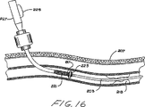
図16は閉塞具拡張可能コーンが展開された、身体通路に挿入された現在の好ましい実施形態の図である。
図17は拡張可能な閉込め部材を開口させる閉塞具組立体を示す、身体通路に挿入された現在の好ましい実施形態のアクセス装置の図である。
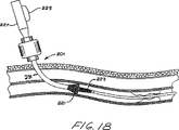
図18は取出し輪郭をなす閉塞具組立体を示す、身体通路に挿入された現在の好ましい実施形態のアクセス装置の図である。
図19は閉塞具組立体が取出され且つ治療バルーンカテーテルが挿入された開口状態の拡張可能な閉込め部材を示す、身体通路に挿入された現在の好ましい実施形態のアクセス装置の図である。
図20は閉塞物を処理するためのアクセス装置にのバルーンの使用を図示する、身体通路に挿入された現在の好ましい実施形態のアクセス装置の図である。
図21は、バルーンカテーテルが閉塞物の塊をアクセス装置の拡張可能な閉込め部材の方に引寄せるとき、身体通路内で使用中の現在の好ましい実施形態のアクセス装置の図である。
図22は現在の好ましい実施形態による拡張可能な閉込め部材の中への閉塞物の塊の閉込めを図示する。
図23はバルーンカテーテルが取出された、現在の好ましい実施形態のアクセス装置の拡張された閉込め部材の図である。
図24は拡張可能な閉込め部材を身体通路からの取出せるようにつぶすために再挿入された閉塞具組立体を示す、現在の好ましい実施形態のアクセス装置の図である。
図25は身体通路からの取出し前の、現在の好ましい実施形態のつぶされた拡張可能な閉込め部材及び閉塞具組立体の図である。
図26は現在の好ましい実施形態のアクセス装置が取出された身体通路の図である。
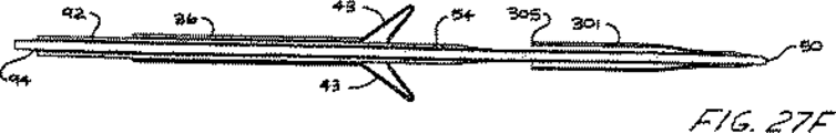
図27A乃至Jは拡張可能な閉込め部材の展開順序を示す、本発明の第4の変形の実施形態の一連の横断面図である。
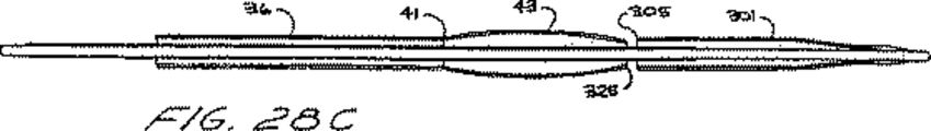
図28A乃至Hは拡張可能な閉込め部材の展開順序を示す、本発明の第5の変形の実施形態の一連の横断面図である。
図29はアクセス装置と治療カテーテルの組合わせを含む更なる実施形態の軸線方向横断面図であり、この図は、治療カテーテルを先細カテーテルの形態で図示する以外、図22と同様である。
図30は、図29に図示した組合わせの軸線方向拡大横断面図である。
図31は、図30の線31−31における、アクセス装置と先細カテーテルの組合わせの半径方向横断面図である。
本発明の好ましい実施形態の詳細な説明
図1に目を向ければ、本発明のアクセス装置30が図示され、アクセス装置30は図2で最も良くわかるようなシース組立体32と、図3で最も良くわかるような、シース組立体32に挿入された閉塞具組立体34とを有する。シース組立体32は外側可撓性チューブ36を有し、外側可撓性チューブ36は近位チューブ端38及び遠位チューブ端41を有する。シース組立体32は付属装置45と、遠位チューブ端41の近くで外側可撓性チューブ36に連結された拡張可能な閉込め部材43とを更に有する。閉塞具組立体34は近位閉塞具端47及び遠位閉塞具端50を有する。閉塞具端領域52は閉塞具拡張可能コーン54と近位部分56とを含む。シース組立体32の拡張可能な閉込め部材43は閉塞具端領域52の近位部分56に連結される。閉塞具組立体34の閉塞具ハンドル58がハンドルコネクタ61によってシース組立体32の付属装置45に連結される。
図2に目を向ければ、シース組立体32の外側可撓性チューブ36は拡張可能な閉込め部材43とコネクタ部分63とを有する。拡張可能な閉込め部材43とコネクタ部分63の間に配置された外側可撓性チューブ36の部分は、好ましくは、中実壁チューブ材の半硬質部分からなり、拡張可能な閉込め部材43は、好ましくは、編組管状構成部材からなる。拡張可能な閉込め部材43は、好ましくは、接着か融着のいずれかによってこの中実壁管状部材に接合される。現在具体化されているように、拡張可能な閉込め部材43は熱融着を使用して中実壁管状部分に結合される。コネクタ部分63は、好ましくは、中実プラスチック構成部材からなり、外側可撓性チューブ36の中実壁管状部分に連結される。コネクタ部分63は外側可撓性チューブ36を付属装置45のチューブコネクタ67に取外し可能に連結する。現在の好ましい実施形態では、コネクタ部分63は、チューブコネクタ67に滑り嵌め可能に合うねじ山(図示せず)を有する。
遠位チューブ端41と近位チューブ端38の間の外側可撓性チューブ36の中に管腔が形成される。この管腔は、好ましくは、閉塞具組立体34のシャフト部分(図3)を収容するように寸法決めされ且つ形成される。外側可撓性チューブ36の管腔は又、その他の器具を取出し可能に収容するのが良い。シース組立体32の側ポート70が、正圧か負圧のいずれかの下で、空気又は流体を外側可撓性チューブ36の管腔に付与したり、それをそこから取出したりするようになっている。閉塞具組立体34(図3)のような器具を、例えば、シース組立体32のハンドルコネクタ61から挿入して拡張可能な閉込め部材43から外に出すのが良い。付属装置45のフィンガータブ71が、2つのフィンガータブ71の形態に応じて、外側可撓性チューブ36の管腔への出し入れ口を開いたりシールしたりするように作用する。
図3に示すように、閉塞具組立体34は、閉塞異端領域52を含む閉塞具シャフト72を有し、閉塞具シャフト72はコネクタ部分74によって閉塞具ハンドル58に連結される。閉塞具拡張可能コーン54を摺動自在アクチュエータ76の移動によって半径方向に拡張、収縮させることができる。現在の好ましい実施形態によれば、閉塞具組立体34の遠位閉塞具端50をシース組立体32のハンドルコネクタ61から挿入する。次いで、遠位閉塞具端を外側可撓性チューブ36の管腔の中を通して移動させ、シース組立体32の拡張可能な閉込め部材43から外に出す。現在、具体化されているように、閉塞具組立体34のコネクタ部分74はハンドルコネクタ61のねじ山を収容する。シース組立体32のハンドルコネクタ61が閉塞具組立体34のコネクタ部分74の中に固着されるとき、閉塞具端領域52はシース組立体32の拡張可能な閉込め部材43から外に遠位方向に延びる。
図4は、導入輪郭、即ち非拡張状態に形成された本発明のアクセス装置30の横断面図である。案内ワイヤ81を有する外側可撓性チューブ36の管腔78が示され、案内ワイヤ81は管腔78に挿入される。案内ワイヤ81は、例えば身体通路へのアクセス装置30の挿入中、アクセス装置30用の補剛材及び先導体の両方として作用する。案内ワイヤ81はアクセス装置30に強度を与え、外側可撓性チューブ36及び閉塞具シャフト72の構成部材を、軽量で、且つ身体通路内の空間を維持するための薄肉構造で製造できるようにする。案内ワイヤ81の使用は又、拡張可能部材43及び/又は54の挿入及び展開中の外側可撓性チューブ36及び閉塞具シャフト72の構成部材の強度要件を軽減させるのに役立つ。
拡張可能な閉込め部材43は近位部材端83及び遠位部材端85を有する。拡張可能な閉込め部材43の近位部材端83は、好ましくは、可撓性チューブ36の中実壁部分に結合され、拡張可能な閉込め部材43の遠位部材端85は結合部分87によって閉塞具シャフト72のまわりに結合される。
外側摺動自在閉塞具スリーブ90が、好ましくは、結合部分87で拡張可能な閉込め部材43の遠位部材端85に融着される。現在具体化されているように、外側摺動自在閉塞具スリーブ90は、外側可撓性チューブ36及び拡張可能な閉込め部材43を挿入マンドレルの上で圧縮状態に保持しながら加熱することによって拡張可能な閉込め部材43の管状メッシュに融着される。この構造により、結合部分87における材料を実質的に厚くせず、且つ結合部分87の直径の増大を最小にする。装置内の最適な空間使用に要求される厳密な公差を維持するために、外側可撓性チューブ36の材料が拡張可能な閉込め部材43の織物に流れ込み、織物の個々の織要素に流れ込み且つそのまわりに流れる。引き続いて、拡張可能な閉込め部材43の織物は、拡張可能な閉込め部材43の織メッシュに曲げ領域107を形成するように折り返され、近位方向に延ばされて、外側可撓性チューブ36の遠位チューブ端41に重なる。可撓性閉込め部材43の近位部材端83は同様の仕方で外側可撓性チューブ36に融着される。
閉塞具シャフト72は外側摺動自在閉塞具スリーブ90と、中間摺動自在閉塞具スリーブ92と、内側固定閉塞具スリーブ94とを有する。案内ワイヤ81は内側固定閉塞具スリーブ94に嵌る。シース組立体32の外側可撓性チューブ36は外側摺動自在閉塞具スリーブ90のまわりに嵌る。外側摺動自在閉塞具スリーブ90の一部分は結合部分87で凹所をなし、それにより、拡張可能な閉込め部材43の遠位部材端85を外側摺動自在閉塞具スリーブ90のこの凹部分の中に収容する。外側摺動自在閉塞具スリーブ90は閉塞具端領域52として拡張可能な閉込め部材43から遠位方向に続いている。更に詳細には、閉塞具端領域52の外側摺動自在閉塞具スリーブ90は中実壁部分97と、閉塞具拡張可能コーン54と、遠位中実壁部分99とを有する。閉塞具拡張可能コーン54は、好ましくは、管状織物構造からなり、該管状織物構造は拡張可能な閉込め部材43の編組材料と同様であるのが良い。閉塞具拡張可能コーン54は、好ましくは、外側摺動自在閉塞具スリーブ90の中実壁部分97と遠位中実壁部分99の間に、即ち近位融着箇所101及び遠位融着箇所103で融着される。外側摺動自在閉塞具スリーブ90の結合部分87は、身体通路へのアクセス装置の挿入中、拡張可能な閉込め部材43を適所に保持する。アクセス装置30を身体通路内に位置決めした後、閉塞具シャフト72をシース組立体32に対して遠位方向に移動させ、それにより、結合部分87を外側摺動自在閉塞具スリーブ90の凹部の中から解放する。
外側摺動自在閉塞具スリーブ90、中間摺動自在閉塞具スリーブ92、及び内側固定閉塞具スリーブ94の目的は、案内ワイヤ81の移動を要求することなしに、外側摺動自在閉塞具スリーブ90の近位融着箇所101と遠位融着箇所103の間の相対移動を容易にすることにある。言い換えれば、案内ワイヤ81は内側固定閉塞具スリーブ94の中に摺動自在に収容される。中間摺動自在閉塞具スリーブ92の遠位端は外側摺動自在閉塞具スリーブ90の中実壁部分97に連結され、内側固定閉塞具スリーブ94の遠位端は遠位中実壁部分99に連結される。内側固定閉塞具スリーブ94の遠位端が中実壁部分99に連結され且つ中間摺動自在閉塞具スリーブ92の遠位端が中実壁部分97に連結されるので、互いに対するこれらの2つの遠位端の移動により、閉塞具拡張可能コーン54の両端101、103を移動させる。
図5に示すように、中間摺動自在アクチュエータスリーブ92の遠位端を内側固定閉塞具スリーブ94の遠位端の方に移動させて、それにより、近位融着箇所101を遠位融着箇所103の方に移動させるのが良い。
図5では、内側固定閉塞具スリーブ94の遠位端が中間摺動自在閉塞具スリーブ92の遠位端の方に近位方向に移動され、閉塞具拡張可能コーン54は半径方向の径が増大した。次いで、拡張可能な閉込め部材43の遠位部材端85を拡張可能な閉込め部材43の近位部材端83の方に移動させるために、閉塞具シャフト72全体が近位方向に移動される。現在具体化されているように、閉塞具端領域52の近位部分56と閉塞具拡張可能コーン54の両方が拡張可能な閉込め部材43に接触して近位方向に押し進み、それにより、遠位部材端85を拡張可能な閉込め部材43の曲げ領域107の周りに移動させる。曲げ領域107は拡張可能な閉込め部材43の長さをほぼ二分し、且つ近位方向への閉塞具拡張可能コーン54の更なる移動を許して、拡張可能な閉込め部材43をコーン形状に形成する。このコーン形状では、拡張可能な閉込め部材43の遠位部分はコーンの内面108と、コーンの遠位方向に面する拡張リムを形成する曲げ領域107とからなる。
かくして、拡張可能な閉込め部材43の内側面108は曲げ領域107の周りに外側面110の方に折れ曲り、コーンを形成する。この折れ曲がり動作は、拡張可能な閉込め部材43の織物状メッシュの拡張限界近くの箇所でおこる。このように形成されたコーンは、外側面110及び内側面108からなる二重壁構造と、トラスを形成するそれらの間の空間とからなる。コーンの遠位方向に面する大リム107は、例えば、身体通路内の内膜組織に密接するようになっている。この曲げ領域107は、コーンのフープ強度を大きく増し、同時に、いかなる露出メッシュ要素端も曲げ領域107から延びない比較的非外傷性の末端特徴を備える、拡張可能な閉込め部材43のメッシュの折り曲げ要素からなる。
拡張可能な閉込め部材43をコーン形状に形成した後、図6に図示するように、閉塞具組立体34の閉塞具シャフト72をコーンから離れるように遠位方向に移動させる。加えて、内側固定閉塞具スリーブ94の遠位端を中間摺動自在閉塞具スリーブ92の遠位端から遠ざけ、それにより、閉塞具拡張可能コーン54をつぶす。閉塞具拡張可能コーン54をつぶした後、閉塞具シャフト72を再び近位方向に移動させる。閉塞具組立体34全体が外側可撓性チューブ36の管腔78から取出されるまで、閉塞具シャフト72を近位方向に移動させる。加えて、案内ワイヤ81を管腔78から取出す。
図7は、拡張可能な閉込め部材43がコーン形状に形成されて遠位方向に面する拡張リム107を有する外側可撓性チューブ36を図示する。管腔78は、治療バルーンカテーテルのような他の器具の引き続いての導入が自由である。図8は、閉塞具組立体34(図3)がシース組立体32から取出され且つ拡張可能な閉込め部材43がコーンに形成されたシース組立体32全体を図示する。
図9乃至12は、閉塞具シャフト112が案内ワイヤ114を収容する単一チューブからなる本発明の変形の実施形態を図示する。閉塞具シャフト112は、拡張可能な閉込め部材118を有する外側可撓性チューブ116に摺動自在に嵌る。拡張可能な閉込め部材118の遠位端121は連結領域123に融着又は接着される。図10に示すように、閉塞具シャフト112を近位方向に移動させるとき、拡張可能な閉込め部材118の遠位端121は拡張可能な閉込め部材118の近位端125の方に移動される。拡張可能な閉込め部材118は拡張し、曲げ領域127のまわりに外方にたわむ。
図4乃至7を参照して上で説明した実施形態のように、閉塞具シャフト112及び外側可撓性チューブ116を互いに対して移動させる間、案内ワイヤ114の遠位端130は定置のままであるのが良い。変形例として、遠位端121は、例えば、連結領域123に機械的に連結されても良い。
図11は図6に相当し、内側面132は外側面134の内側に折り曲げられ、遠位方向に面する大リム127がコーンを形成する。しかしながら、この実施形態の閉塞具シャフト112を取出し前に遠位方向に移動させる必要がないけれども、その代わりに、閉塞具シャフト112を図11の形態から外側可撓性チューブ116の管腔138(図12)の外に近位方向に移動させるのが良い。図4乃至7の実施形態では、管腔78からの閉塞具シャフト72の取出し前、閉塞具シャフト72を前方に移動させる必要もないし、閉塞具拡張可能コーン54をつぶす必要もない。しかしながら、図4乃至7の実施形態は、閉塞具シャフト72の取出し前に閉塞具拡張可能コーン54をつぶすことから利益を得る。図4乃至7の実施形態の好ましい操作が、中間摺動自在閉塞具スリーブ92及び内側固定閉塞具スリーブ94の遠位端を互いに遠ざけ、それにより、閉塞具シャフト72の取出し前、閉塞具拡張可能コーン54に引張りを付与し且つこの閉塞具拡張可能コーン54の輪郭即ち直径を縮小させることを含むことに注目すべきである。
図13A乃至13Gは、遠位端147を有する案内ワイヤ145が内側摺動自在閉塞具スリーブ152に挿入された本発明の別の実施形態を図示する。内側摺動自在閉塞具スリーブ152は外側閉塞具閉込めスリーブ154に嵌り、外側閉塞具閉込めスリーブ154はシース組立体の外側可撓性チューブ156に嵌る。拡張可能な閉込め部材158が外側可撓性チューブ156に連結され、外側閉塞具閉込めスリーブ154の保持端161にも連結される。内側摺動自在閉塞具スリーブ152は閉塞具拡張可能コーン165を有する。身体通路へのアクセス装置の挿入中、外側閉塞具閉込めスリーブ154の2つの保持端161は拡張可能な閉込め部材158の遠位端167を適所に保持する。次いで、図13Bに示すように、閉塞具拡張可能コーン165を拡張させ、近位方向に移動させて拡張可能な閉込め部材158の遠位端167に接触させる。拡張可能な閉込め部材158は曲げ部分172のまわりに曲り、それにより、コーン即ち漏斗を形成する。次いで、図13Cに示すように、閉塞具拡張可能コーン165をつぶし、拡張可能な閉込め部材158の遠位端167を外側閉塞具閉込めスリーブ154の保持端161から解放する。
次いで、拡張可能な閉込め部材165、外側閉塞具閉込めスリーブ154、内側摺動自在閉塞具スリーブ152、及び案内ワイヤ145を、図13Dに図示するように、外側可撓性チューブ156から取出す。現在好ましい実施形態によれば、アクセス装置を身体通路から取出す前、拡張可能な閉込め部座158をつぶして戻し低輪郭形態にする。変形例として、拡張可能な閉込め部材158をつぶさないで外側可撓性チューブ156を身体通路から取出しても良い。図13E乃至13Gに示すように、閉塞具拡張可能コーン165を拡張させ、拡張可能な閉込め部材158の遠位端167に接触させて遠位方向に移動させ、それにより、拡張可能な閉込め部材158をつぶす。図14A乃至14Dは、前の実施形態の閉塞具拡張可能コーンを拡張直径部分178と置換えた本発明の別の実施形態を図示する。内側摺動自在閉塞具スリーブ181が外側閉塞具閉込めスリーブ183に嵌り、外側閉塞具閉込めスリーブ183は外側可撓性チューブ185に嵌る。外側可撓性チューブ185は遠位端190を有する拡張可能な閉込め部材187に連結され、遠位端190は外側閉塞具閉込めスリーブ183の保持端192によって保持される。
この実施形態では、図14Bに図示するように、保持端192の近位方向の移動で拡張可能な閉込め部材187を圧縮させ、遠位端190を曲げ部分194のまわりに移動させ、それにより、コーンを形成する。保持端192を近位方向に更に移動させ、それにより、図14Cに示すように、拡張可能な閉込め部材187の遠位端190を解放する。次いで、拡張直径部分178を近位方向に移動させ、保持端192に密接させる。内側摺動自在閉塞具スリーブ181、外側閉塞具閉込めスリーブ183、及び拡張直径部分178のすべてを近位方向に移動させ、外側可撓性チューブ185の管腔198の外に出す。
今、本発明のアクセス装置の操作を図15乃至26を参照して説明する。図15を参照して、アクセス装置201を患者の皮膚207の穿刺部位205から身体通路214の血管の穿刺孔212を通して配置済みの案内ワイヤ203の上に挿入する。アクセス装置201を身体通路214の管腔219内の閉塞物質218の近位の所望領域まで案内ワイヤ203の上で押す。拡張可能な閉込め部材221及び閉塞具拡張可能コーン223の輪郭は、閉塞具ハンドル227の摺動自在閉塞具225を遠位方向位置にして、これらの部材221、223の引張りを維持することによって最小に維持される。いったんアクセス装置201を身体通路214の管腔219に位置決めしたら、拡張可能な閉込め部材221及び閉塞具拡張可能コーン223の引張りを解放する。
図16に示すように、摺動自在アクチュエータ225を閉塞具ハンドル227の第2近位方向位置まで移動させ、その結果、閉塞具拡張可能コーン223は拡張する。閉塞具拡張可能コーン223を前方に圧縮し及び/又は押し、それが拡張形態に押すとき、(図4で最も良く分かるような)結合部分87は破壊される。次いで、閉塞具拡張可能コーン223を拡張可能な閉込め部材221の遠位端に接触させて近位方向に移動させ、その結果、拡張可能な閉込め部材221は拡張する。図17は、どのように閉塞具拡張可能コーン223が、拡張可能な閉込め部材221をコーン形状に押すのに使用されるのかを図示する。完全に拡張した閉塞具拡張可能コーン223を拡張可能な閉込め部材221の遠位端に接触させて近位方向に引張り、ついには拡張可能な閉込め部材221のこの遠位端は内側に曲がり始める。いったん拡張可能な閉込め部材221がコーン形状に形成されたら、完全に拡張した閉塞具拡張可能コーン223をコーン形状の中に、そしてアクセス装置の外側チューブ231の中に近位方向に押す。
いったん拡張可能な閉込め部材221がコーン即ち漏斗形状に形成されたら、引張りを閉塞具拡張可能コーン223に対して再び配置し、その結果、閉塞具拡張可能コーン223をつぶす。この引張りは閉塞具ハンドル227の摺動自在アクチュエータ225によって供給される。閉塞具拡張可能コーン223の輪郭を最小直径まで縮小させた後(図18)、閉塞具拡張可能コーン223をアクセス装置201の外側チューブ231の中を通して取出す。
案内ワイヤ203を含む閉塞具組立体を外側チューブ231から取出した後、図19に示すように、治療バルーンカテーテル232をチューブ231の管腔に入れて配置する。バルーン234を拡張させる前、治療バルーンカテーテル232を閉塞物質を越えるように遠位方向に前進させる。更に、その他の器具を外側チューブ231から挿入しても良い。治療バルーンカテーテル232を閉塞物質218に対して遠位方向の場所で拡張させ、次いで、閉塞物質218を拡張可能な閉込め部材221によって形成された漏斗の拡張開口の方に、そしてその中に近位方向に押す。閉塞物質218が拡張可能な閉込め部材221の漏斗に押し込められるとき、取出し作業を側ポート70(図2)からの吸引の付与によって助けるのが良い。図21は、閉塞物質218を治療バルーンカテーテル232のバルーン234によって拡張可能な閉込め部材221内に圧縮するところを図示する。図22は拡張可能な閉込め部材221の中に完全に補足された閉塞物質218を示し、図23は、バルーン234の直径を縮小させてそれを取出した後の拡張可能な閉込め部材221及び外側チューブ231を図示する。バルーン234は吸引の連続付与で外側チューブ231の中を通って近位方向に引寄せられ、それにより、閉塞物質218を移送して外側チューブ231の外に出す。
いったん閉塞物質218が外側チューブ231から取出されたら、図24、25に図示するように、閉塞具組立体を外側チューブ231に再挿入する。閉塞具拡張可能コーン223が拡張可能な閉込め部材221の近位端に到達したらそれを拡張させて、拡張可能な閉込め部材221の内側に曲げられた端に係合させる。閉塞具を遠位方向に更に移動させるとき、拡張可能な閉込め部材221によって形成された漏斗は低輪郭形態に戻される。引き続いて、図25に示すように、閉塞具拡張可能コーン223も低輪郭形態に縮小させ、アクセス装置210を取出す。図26は、アクセス装置201の取出し後の身体通路214及び皮膚207を図示する。最小の穿刺孔205、212があいた閉塞のない管腔219が残る。
図27A乃至27Jは本発明の第4の変形の実施形態を図示する。案内ワイヤ301が内側固定閉塞具スリーブ303及び外側摺動自在閉塞具スリーブ305に嵌る。両面シース307が近位シース端309及び遠位シース端311を有する。現在具体化されているように、両面シース307は案内ワイヤ301の遠位端315に固着される。外側摺動自在閉塞具スリーブ305は、その遠位部分に連結された閉塞具拡張可能コーン317を有する。外側可撓性チューブ321が外側摺動自在閉塞具スリーブ305及び閉塞具拡張可能コーン317のまわりに嵌る。外側可撓性チューブ321は、拡張可能な閉込め部材333に連結された遠位チューブ端330を有する。拡張可能な閉込め部材333は、例えば、身体通路への装置の挿入中、両面シース307の下に嵌る。現在具体化されているように、両面シース307は拡張可能な閉込め部材333の材料と同様の編組材料からなる。
操作の際、両面シース307は拡張可能な閉込め部材333を覆い、その結果、血管への挿入時、拡張可能な閉込め部材333を拡張させるように作用する力が両面シース307に、両面シース307の材料を拡張させるのではなく加圧する方向に付与される。装置が身体通路内の適所に置かれた後、両面シース307を遠位方向に移動させ、その結果、図27Bに示すように、両面シース307の近位シース端309は拡張可能な閉込め部材333の遠位端よりも向こうにある。次いで、図27Cに図示するように、両面シース307を遠位方向に更に移動させて、閉塞具拡張可能コーン317の展開に備える。閉塞具拡張可能コーン317は拡張可能な閉込め部材333によって形成された管腔を貫通して遠位方向に移動され、ついには図27Dに図示するように閉塞具拡張可能コーン317を拡張させることができるようになる。
引き続いて、閉塞具拡張可能コーン317を拡張可能な閉込め部材333の遠位端350に接触させて近位方向に移動させる。拡張可能な閉込め部材333の遠位端350に接触させての閉塞具拡張可能コーン317の移動により、図27Eに図示するように、拡張可能な閉込め部材333を拡張させる。閉塞具拡張可能コーン317を拡張可能な閉込め部材333(図27E)の中に移動させた後、図27Fに図示するように、閉塞具拡張可能コーン317を小直径形態につぶす。引き続いて、図27Gに図示するように、閉塞具拡張可能コーン317を拡張可能な閉込め部材333の中に、そして外側可撓性チューブ321の中に近位方向に移動させる。加えて、図27Gに図示するように、両面シース307を拡張可能な閉込め部材333に接触させて近位方向に移動させる。両面シース307を拡張可能な閉込め部材333に接触させて、図27Iに図示するように、近位シース端309が遠位シース端311を越えて移動されるまで近位方向に更に移動させる(図27H)。遠位端315を外側可撓性チューブ321の中を通して引張るとき、遠位シース端311を越える近位シース端309の移動は、図27Jに図示するように、両面シース307を内側に曲げ、裏返す。
図28A乃至28Hは、第4の変形の実施形態の閉塞具拡張可能コーン317を使用しない、本発明の第5の変形の実施形態を図示する。外側可撓性チューブ321を形成する遠位端315の引き寄せ中、両面シース307を内側に曲げ、裏返すとき、拡張可能な閉込め部材333を完全な拡張形態まで押す。
本発明の更なる実施形態を図29乃至31に図示する。図29に最も良く図示するように、この組合わせは、閉塞物218を身体通路214から取出す際に使用されるようになっているアクセス装置201及び治療バルーンカテーテル232を含む。
この組合せでは、アクセス装置201は前述の実施形態のいかなるものをも含んでも良いけれども、治療カテーテル232は、好ましくは、前述の米国特許出願第08/303,427号の出願人によって開示され且つ権利が主張されたもののような先細の種類のものである。この型式のカテーテル232は、その操縦性能を最大にし且つ閉塞物218を取出すのに必要とされる操作回数を最小にするので、特に有利であることがわかっている。
これらの利点を、アクセス装置201及びカテーテル232の遠位端部を図示する図30を参照してより良く理解することができる。この図では、アクセス装置201が遠位端部403をもったチューブ401の形態を有し、且つ閉込め部材221が遠位端部403に取付けられていることが明らかである。チューブ401は直径Dを有する軸線方向管腔を含む。
この実施形態の治療カテーテル232は比較的大きい外径d1をもった近位端部405及び比較的小さい外径d2をもった遠位端部407とを有する。チューブ401の内径Dとカテーテル232の外径dの間に閉込め領域409が形成される。閉塞物質218がカテーテル232及びバルーン234の近位方向移動によってチューブ401の中に引き込まれるとき、チューブ401とカテーテル232の間のこの領域409は閉塞物質218を受入れるようになっている。この領域409の容積を最大にすることは、チューブ401がより大きな容積の閉塞物質218をカテーテル232の一回一回の操作で受入れられるようにする。かくして、閉込め領域409が大容積を備えるとき、単一の閉塞物218をカテーテル232のただ一回の操作で身体通路から完全に取出すことができる。
閉込め領域409はチューブ401の内径D及びカテーテル232の外径d2に応じて以下の式で決められる容積を有する。

米国特許出願第08/303,427号で論じられた理由及びバルーン234の膨張特性に関する理由のために、寸法Lは式Iで制限されなければならない。これは容積Vを最大にするための変更を、(1)チューブ401の内径Dを最大にしたままにするか、或いは(2)カテーテル232の直径d2を最小にしたままにする。直径Dは、もちろん、身体通路214の大きさによって制限されるけれども、好ましい実施形態では、7F乃至9Fほどの大きさであるのが良い。
カテーテル232の遠位端部407の直径d2を最小、とはいってもバルーン234の膨らまし及びすぼませを許す程度にするのが良い。一つの実施形態では、寸法d2は2Fに過ぎないのが良い。しかしながら、この寸法はカテーテル232に遠位端部407で非常に定形性のないくたっとした特性を与える。カテーテル232に2Fに過ぎない直径を与えることは又、バルーン234の寸法を約3Fに制限する。非拡張状態で3Fのバルーンは、拡張状態では、約6Fまで拡張させることができるに過ぎない。バルーン234についてのこの寸法はチューブ401の最大直径Dを満たさないので、より大きなバルーン234が好ましい実施形態に望まれる。
バルーン234が非拡張状態で4Fの直径を備えるとき、拡張状態ではその直径を約9Fまで増加させることができる。約3Fの直径d1をもった遠位端部を有する4Fのバルーンをカテーテル232に形成するのが良い。
カテーテル232はその全長にわたって3Fの一定直径を備えても良いけれども、この寸法は、押す能力及び舵取り能力の両方を欠き比較的くたっとしていることがわかっている。しかしながら、カテーテル232が図28に図示するような先細形態を備えるとき、カテーテルはその近位端部及びその長さの多くの部分にわたってより大きい直径d1有して、より優れた操縦性能を得る。
これらの考察に基づいて、アクセス装置201及びカテーテル232に好ましい寸法は以下の範囲に最適化されるべきであると信じる: D=7F−9F;d1=4F−5F; d2=2F−3F。
バルーン234の直径は、好ましくは、収縮状態でdよりも0乃至1F大きい直径を有し、拡張状態で約Dと等しい、又は好ましくはDよりも大きい直径を有する範囲内にある。例示のように、バルーン234は約3F乃至5Fの収縮直径を有するのが良い。好ましい実施形態では、バルーン234は、収縮状態で4Fの直径を有し、拡張状態で9Fの直径を有する。
本発明の例示の実施形態を示し且つ説明したけれども、上述の実施例に加えて、多くのその他の変化、変更、代替例を当該技術において通常の技術を有するものによって、本発明の精神及び範囲から必然的に逸脱することなく作ることができる。 Background of the Invention
The present invention generally relates to an apparatus for removing occlusive material from a body passage, and more particularly, a first small diameter for initial insertion into the body passage and a first for performing removal of the occlusive material. The present invention relates to an access device that can be formed between two large diameters.
The prior art includes many devices for removing occlusive material from body passages. When the body passage consists of blood vessels, occlusive substances include platelets, blood clots, embolus, clots, and fat deposits. In other cases, the occlusion may result from stones or stenosis.
A catheter is usually inserted into the blood vessel for the purpose of removing occlusive material from the vessel wall. In a widely used technique commonly referred to as embolectomy / thrombectomy, a catheter with a balloon attached to the tip is introduced into a blood vessel through a surgical incision. A catheter with a balloon attached to the tip is advanced to the location of the occlusive material or obstruction, and then the balloon is inflated at a location within the vessel beyond the location of the occlusive material. The catheter containing the attached balloon is then pulled back to the insertion site. In this manner, the balloon pushes the occlusive material to the insertion site and removes the occlusive material through the incision at the insertion site. When occluding material is pulled away from the vessel wall using this technique, the occluding material often tends to disperse and move in the blood flow within the vessel. This dispersion can make it difficult to collect and remove occlusive material, and migration can put patients at risk of acute trauma. Thus, the challenges associated with this embolectomy technique include the efficient collection and removal of occlusive material while preventing occlusive material migration and dispersion. There are other percutaneous methods in the prior art for revascularization of blood vessels. One transdermal method involves the use of laser energy to evaporate the stenotic material. Another percutaneous method, commonly referred to as aspiration embolectomy / thrombotomy, relies on negative pressure to collect the occlusive material.
Percutaneous or minimally open access to blood vessels in the case of balloon catheters requires, for example, a catheter with a very small diameter that fits into a small incision in the blood vessel. However, once the catheter enters the blood vessel, the portion of the catheter needs to exhibit a large contour extraction interface for efficient removal of the occlusive material from the vessel lumen.
In an attempt to meet this dual functional requirement of a small incision diameter and a large intraluminal working diameter, the prior art has had a catheter and a sheath. U.S. Pat. No. 5,011,488 to Ginsburg discloses the use of an expanding funnel-shaped sheath for use in removing a thrombus or embolus (occlusive material) from a blood vessel. The funnel is deployed by expanding the expanding tunnel-shaped sheath from within the second sheath, thereby expanding the compressed funnel radially. The use of this second sheath tends to increase the overall diameter of the device, thus increasing the size of the incision required to insert the device. In addition to not achieving an optimal small insertion diameter, this device also does not provide an optimal intraluminal large working diameter. The optimal large intraluminal working diameter facilitates the insertion and removal of larger instruments through the sheath. This prior art of inserting both the introducer sheath and the preformed funnel-shaped sheath into the body passage and subsequently removing the introducer sheath requires a large introducer incision, and after removing the introducer sheath, a smaller diameter preform. Form a seal around the funnel-shaped sheath. In other words, the prior art dual sheath combination is large enough to accommodate the introducer sheath and subsequently seals around a smaller preformed funnel-shaped sheath left in place after removal of the introducer sheath. An initial incision into the body passage is required that is small enough to properly form. Subsequently, it is difficult to obtain a good seal with this prior art device since the initial incision size cannot be reduced to accommodate the funnel-shaped sheath.
Other devices that provide access to relatively inaccessible regions of blood vessels are disclosed in US Pat. Nos. 4,530,698 and 4,437,5859. Although needle and sheath combinations that can be used for drug delivery, blood collection and dialysis have been proposed by the prior art, these devices have different structures to solve different problems than the removal of occlusive material from body passages. Have Fogarty U.S. Pat. No. 5,234,425 discloses a variable diameter sheath made of a synthetic elastomeric material that can be stretched to reduce the diameter. However, this variable diameter sheath is not used to remove occlusive material. Instead, the primary purpose of this device is to provide a single-thickness thin inner sheath in the body passage lining, which is introduced into the body passage in a reduced diameter, and subsequently expanded, Fit the inner wall of the passage. The variable diameter sheath has a tubular braid encapsulated within a high elongation silicone polymer coating. There is no prior art device that discloses a sheath having a lumen for receiving a catheter that can be efficiently formed between a minimum diameter and a maximum diameter and that facilitates removal of occlusive material from a body passage.
Summary of the Invention
The access device of the present invention does not require an initial large incision, ie, a large incision that subsequently forms a seal around a small diameter funnel-shaped sheath. The access device of the present invention can be inserted into a body passage or duct using minimal invasive techniques. The distal portion of the access device of the present invention is expanded in diameter, and the diameter of the portion that contacts the incision region of the vessel remains constant. The access device fits into an optimal small incision in the blood vessel and the portion of the access device that contacts the incision region of the blood vessel does not change in diameter, thus forming an effective seal.
The expanded diameter portion of the distal portion of the access device may have any of a variety of predetermined shapes and dimensions depending on the specific needs required by the predetermined method. According to one feature of the invention, the distal end of the access device may take the form of a forward facing funnel that constitutes a mechanism for removing occlusive material from the body passage.
According to one aspect of the present invention, a single sheath having an optimal minimum diameter is inserted through an incision in the body passage. The single sheath of the access device is inserted into the body passage incision with the expandable confinement member of the access device in the smallest diameter configuration. The expandable containment member is held in a minimum diameter configuration using structures other than prior art large diameter outer sheaths. The structure used by the present invention to profile the expandable containment member to a minimum diameter can be subsequently removed from the lumen of the access device once the expandable containment member is expanded. Thus, in contrast to the prior art, the mechanism for contouring the expandable containment member does not increase the outer diameter of the access device. When the structure for contouring the expandable confinement member in the small diameter form is no longer needed, the structure can be removed from the body passage without affecting the outer diameter of the access device near the incision in the body passage. Can be taken out.
According to one aspect of the invention, the access device includes an outer tube having a proximal tube end and a distal tube end, and a lumen extending between the proximal tube end and the distal tube end. An obturator assembly having a proximal obturator end and a distal obturator end is removably and concentrically disposed within the lumen of the outer tube. An expandable confinement member having a proximal member end and a distal member end is coupled to both the distal tube end and the distal obturator end. The proximal member end is connected to the distal tube end, and the distal member end is releasably connected to the distal obturator end. The expandable confinement member may be expanded by relative movement between the proximal member end and the distal member end. This relative movement corresponds to the relative movement between the outer tube and the obturator assembly in the opposite direction. During insertion of the access device into the body passage, the proximal member end of the expandable confinement member is held away from the distal end of the expandable confinement member, thereby disengaging the expandable confinement member. Hold in expanded state. After the access device is inserted into the body passage, the proximal member end and the distal member end are moved relative to each other to expand the expandable confinement member. The obturator assembly is then removed from the access device, thereby forming an unobstructed lumen in the outer tube. The lumen of the outer tube then facilitates the insertion and removal of instruments and materials. For example, a treatment balloon catheter may be inserted into the lumen to facilitate embolization or thrombus removal. The access device of the present invention further includes a guide wire adapted to be inserted into the obturator assembly. The guide wire acts as a stiffener for the access device and as a leading conductor.
According to another feature of the invention, the outer tube of the access device has a predetermined outer diameter and an axis extending between the proximal tube end and the distal tube end. An expandable confinement member is attached to the outer tube at the distal tube end and has a non-expanded diameter approximately equal to the outer diameter of the outer tube. The outer tube may include a solid wall tubular member and the expandable containment member may include a braided tubular component. The solid wall tubular member and the expandable confinement member are joined together by adhesion or fusion, and the expandable confinement member is a barrier to flow in the body passage when the expandable confinement member is expanded. It may be coated with a water-impermeable elastomeric material that forms
The obturator assembly of the present invention is initially coupled to an expandable containment member to facilitate insertion of the access device into the body passage. After insertion of the access device, the obturator assembly is removed from the expandable confinement member, thereby facilitating movement of the obturator assembly within the expandable confinement member. The obturator assembly of the present invention includes an intermediate slidable obturator sleeve that has a proximal intermediate sleeve end and a distal intermediate sleeve end. A lumen extends between the proximal intermediate sleeve end and the distal intermediate sleeve end. The inner fixed obturator sleeve has a proximal inner sleeve end and a distal inner sleeve end and is concentrically disposed within the lumen of the intermediate slidable obturator sleeve. The obturator further includes an obturator expandable cone, the obturator expansion cone having a proximal cone end and a distal cone end. The distal cone end is connected to the distal inner sleeve end and the proximal cone end is connected to the distal intermediate sleeve end. The obturator expandable cone may be expanded by relative movement between the proximal cone end and the distal cone end, the relative movement being affected by the relative movement of the distal inner sleeve end and the distal intermediate sleeve end in opposite directions. Receive. Once the obturator expandable cone is expanded, the obturator is brought into contact with the expandable confinement member and moved proximally, thereby compressing the expandable confinement member about its axis. The expandable confinement member is bent about the midpoint of the expandable confinement member disposed between the proximal member end and the distal member end. The expandable confinement member forms a cone when the proximal member end is moved sufficiently close to the distal member end and the distal member end is moved proximally beyond the midpoint of the expandable member. .
According to the method of removing occlusive material from a body passage of the present invention, a tubular access device is inserted into the body passage and the tubular access device is inserted into the body passage to a first location where the occlusive material is placed in the body passage. Move in the distal direction. The distal end of the expandable confinement member is moved toward its proximal end, thereby expanding the expandable confinement member into a cone shape having a relatively large diameter. The accessor obturator assembly is removed from the lumen of the outer tube, the treatment catheter is inserted into the outer tube, the treatment catheter is moved distally within the body passage past the first location, and the treatment catheter is occluded. It reaches the second point on the distal side of the substance. The treatment catheter is expanded and then retracted proximally from the second location toward the expandable confinement member. Movement of the expanded treatment catheter in the proximal direction carries the occlusive material into the expandable confinement member and then into the lumen of the outer tube. Once the occlusive material is removed from the lumen of the outer tube and the treatment catheter is removed from the lumen, the obturator assembly is inserted back into the lumen of the outer tube and can be used to expand it. Crush the member into small diameter form. The access device is then removed from the body passage along with the expandable containment member in the form of a small profile.
In various combinations of access devices and treatment catheters, a containment area is formed inside the access device and outside the catheter. This confinement region has a volume depending on the inner diameter of the access device and the outer diameter of the catheter. It has been found advantageous to provide a large volume in this confinement region in order to accommodate a large portion of the occlusive material in a single operation of the catheter. The larger the volume, the less catheter manipulation required to completely remove the obstruction.
The volume of this confinement region may be increased by reducing the outer diameter of the catheter. However, the catheter relies on a large diameter to improve steering performance, such as the pushing and steering capabilities of the catheter. In order to meet these dual requirements, a tapered catheter has been found to be particularly advantageous. For example, a preferred combination of the tapered catheter disclosed and claimed by the applicant of US patent application Ser. No. 08 / 303,427, filed Sep. 9, 1994, entitled Embolectomy catheter and method of making the same. Good to use. This application example is incorporated herein.
Thus, a further aspect of the present invention includes a combination adapted to remove an obstruction from a body passage. The combination includes an access device having the form of a tube with a proximal end and a distal end having a first inner diameter. A catheter having a second outer diameter proximal end and a third outer diameter distal end is insertable into the tube, the distal end of the tube and the distal end of the catheter having a first inner diameter and A confinement region having a volume determined by the third outer diameter is formed. An engagement structure is disposed at the distal end of the catheter. The catheter is steerable distally through the tube to position the engagement structure on the side of the obstruction opposite the access device, and close to retract the obstruction to the containment area. It can move in the direction of position. The second diameter of the catheter is larger than the third diameter of the catheter to improve catheter steering performance without reducing the volume of the containment area.
In a further aspect, the present invention includes a method for removing an obstruction from a body passage. The method includes providing an access device having a lumen extending between a proximal end and a distal end of a first inner diameter. The access device is inserted into the body passage to the proximal position of the obstruction. A catheter is provided having a shaft with a second diameter proximal end and a third diameter distal end, and an engagement structure is disposed at the distal end of the shaft. The catheter is positioned in the lumen of the access device so as to define a confinement region between the distal end of the access device and the distal end of the catheter. This confinement region has a volume determined by the first inner diameter and the third outer diameter. The catheter is then steered distally through the lumen of the access device to position the engagement structure distally from the obstruction. Steering the catheter in the proximal direction draws the obstruction into the containment area constituted by the access device and the catheter. In order to improve the steering performance of the catheter without reducing the volume of the containment area, the catheter is formed with a proximal end having a second diameter that is larger than the third diameter of its distal end.
The invention, together with its additional features and advantages, can best be understood by the following description in conjunction with the accompanying drawings.
[Brief description of the drawings]
FIG. 1 is a side view of an assembled access device according to a presently preferred embodiment.
FIG. 2 is a side view of a sheath assembly according to a presently preferred embodiment.
FIG. 3 is a side view of an obturator assembly according to a presently preferred embodiment.
FIG. 4 is a cross-sectional view of an access device in an introduction profile or non-expanded state, according to a presently preferred embodiment.
FIG. 5 is a cross-sectional view of the deployed access device showing the obturator expandable cone expanding the expandable containment member of the access device according to the presently preferred embodiment.
FIG. 6 is a cross-sectional view of the deployed access device showing the non-expanded obturator expandable cone in accordance with the presently preferred embodiment.
FIG. 7 is a view of an access device with the obturator removed and the expandable containment member fully deployed in accordance with the presently preferred embodiment.
FIG. 8 is a side view of the access device with the obturator assembly removed and the expandable containment member deployed.
FIG. 9 is a cross-sectional view of a first variant embodiment of the present invention having an introduction profile.
FIG. 10 is a cross-sectional view of a first variant embodiment of the present invention showing the expandable confinement member partially deployed.
FIG. 11 is a cross-sectional view of a first variant embodiment of the present invention showing the expandable confinement member fully deployed.
FIG. 12 is a cross-sectional view of a first variant embodiment of the present invention with the obturator assembly removed and the expandable containment member fully deployed.
13A-G are a series of cross-sectional views of a second alternative embodiment of the present invention illustrating the expansion and deployment order.
14A-D are cross-sectional views of a third variant embodiment of the present invention showing the deployment sequence of the expandable confinement members.
FIG. 15 is a view of the presently preferred embodiment inserted into a body passage.
FIG. 16 is a view of the presently preferred embodiment inserted into a body passage with the obturator expandable cone deployed.
FIG. 17 is a view of the presently preferred embodiment of the access device inserted into a body passage showing the obturator assembly opening the expandable confinement member.
FIG. 18 is a view of the presently preferred embodiment of the access device inserted into the body passageway showing the obturator assembly having a withdrawal profile.
FIG. 19 is a view of the presently preferred embodiment of the access device inserted into a body passage showing the openable expandable confinement member with the obturator assembly removed and the treatment balloon catheter inserted.
FIG. 20 is a view of the presently preferred embodiment access device inserted into a body passage illustrating the use of a balloon in the access device to treat an obstruction.
FIG. 21 is an illustration of the presently preferred embodiment of the access device in use within the body passageway when the balloon catheter draws the mass of obstruction toward the expandable confinement member of the access device.
FIG. 22 illustrates confinement of an obstruction mass into an expandable confinement member according to a presently preferred embodiment.
FIG. 23 is an expanded confinement member view of the presently preferred embodiment access device with the balloon catheter removed.
FIG. 24 is a view of the presently preferred embodiment of the access device showing the obturator assembly reinserted to collapse the expandable confinement member for removal from the body passage.
FIG. 25 is a view of the collapsed expandable containment member and obturator assembly of the presently preferred embodiment prior to removal from the body passage.
FIG. 26 is a view of the body passageway from which the presently preferred embodiment access device has been removed.
27A-J are a series of cross-sectional views of a fourth alternative embodiment of the present invention showing the deployment sequence of the expandable confinement members.
28A-H are a series of cross-sectional views of a fifth alternative embodiment of the present invention showing the deployment sequence of the expandable confinement members.
FIG. 29 is an axial cross-sectional view of a further embodiment that includes a combination access device and treatment catheter, which is similar to FIG. 22 except that the treatment catheter is shown in the form of a tapered catheter.
30 is an axially enlarged transverse sectional view of the combination shown in FIG.
31 is a radial cross-sectional view of the access device and tapered catheter combination at line 31-31 of FIG.
Detailed Description of the Preferred Embodiments of the Invention
Turning to FIG. 1, an
Turning to FIG. 2, the outer
A lumen is formed in the outer
As shown in FIG. 3, the
FIG. 4 is a cross-sectional view of the
The
An outer slidable obturator sleeve 90 is preferably fused to the distal member end 85 of the
The
The purpose of the outer slidable obturator sleeve 90, the intermediate
As shown in FIG. 5, the distal end of the intermediate
In FIG. 5, the distal end of the inner fixed
Thus, the
After the
FIG. 7 illustrates the outer
FIGS. 9-12 illustrate an alternative embodiment of the present invention in which the
As with the embodiment described above with reference to FIGS. 4-7, the
FIG. 11 corresponds to FIG. 6 in which the
FIGS. 13A-13G illustrate another embodiment of the present invention in which a guide wire 145 having a distal end 147 is inserted into the inner
The
In this embodiment, as shown in FIG. 14B, proximal movement of the retaining
The operation of the access device of the present invention will now be described with reference to FIGS. Referring to FIG. 15, the
As shown in FIG. 16, the
Once the
After the obturator assembly including
Once the
Figures 27A-27J illustrate a fourth variant embodiment of the invention. A
In operation, the double-
Subsequently, the obturator expandable cone 317 is moved proximally against the distal end 350 of the expandable confinement member 333. Movement of the obturator expandable cone 317 in contact with the distal end 350 of the expandable confinement member 333 causes the expandable confinement member 333 to expand, as illustrated in FIG. 27E. After the obturator expandable cone 317 is moved into the expandable containment member 333 (FIG. 27E), the obturator expandable cone 317 is collapsed to a small diameter configuration, as illustrated in FIG. 27F. Subsequently, the obturator expandable cone 317 is moved proximally into the expandable confinement member 333 and into the outer
28A-28H illustrate a fifth variant embodiment of the invention that does not use the obturator expandable cone 317 of the fourth variant embodiment. During pulling of the
A further embodiment of the invention is illustrated in FIGS. As best illustrated in FIG. 29, this combination includes an
In this combination, although the
These advantages can be better understood with reference to FIG. 30 illustrating the distal end of the
The
The
For reasons discussed in US patent application Ser. No. 08 / 303,427 and for reasons related to the inflation characteristics of
Diameter d of
When the
Although the
Based on these considerations, we believe that the preferred dimensions for
The diameter of the
While exemplary embodiments of the present invention have been shown and described, in addition to the examples described above, the spirit and scope of the present invention is determined by many other variations, modifications, and alternatives having ordinary skill in the art. Can be made without inevitably deviating from.
Claims (30)
近位閉塞具端及び遠位閉塞具端を有し、前記外側チューブの管腔内に取出し可能に且つ同心に配置される閉塞具組立体と、を有し、前記近位閉塞具端は、前記近位チューブ端を越えて近位方向に延び、前記遠位閉塞具端は、前記遠位チューブ端を越えて遠位方向に延び、
更に、前記遠位チューブ端に連結された近位部材端及び前記遠位閉塞具端に引離し可能に連結された遠位部材端を有する拡張可能部材を有し、
前記閉塞具組立体を前記外側チューブに対して相対的に近位方向に移動させることにより、前記拡張可能部材は、前記近位部材端と前記遠位部材端の間の相対移動によって拡張可能であり、
前記閉塞具組立体を前記外側チューブに対して相対的に遠位方向に移動させることによって前記遠位閉塞具端を前記遠位部材端よりも遠位方向に移動させるとき、前記遠位部材端は前記遠位閉塞具端から引離され、前記管腔が遠位方向に通じ、
前記閉塞具組立体は、
近位中間スリーブ端、遠位中間スリーブ端、及び前記近位中間スリーブ端と前記遠位中間スリーブ端との間に延びる管腔を有する中間摺動自在閉塞具スリーブと、
近位内側スリーブ端及び遠位内側スリーブ端を有し、且つ前記中間摺動自在閉塞具スリーブの管腔内に同心に配置される内側固定閉塞具スリーブと、
閉塞具拡張可能コーンと、を有し、
前記閉塞具拡張可能コーンは、前記遠位中間スリーブ端に連結された近位コーン端及び前記遠位内側スリーブ端に連結された遠位コーン端を有し、且つ、反対方向における遠位内側スリーブ端及び遠位中間スリーブ端の相対移動から生じる、前記近位コーン端と前記遠位コーン端の間の相対移動によって拡張可能であることを特徴とする身体通路へ導入可能なアクセス装置。An outer tube having a proximal tube end, a distal tube end, and a lumen extending between the proximal tube end and the distal tube end;
An obturator assembly having a proximal obturator end and a distal obturator end and removably and concentrically disposed within the lumen of the outer tube, the proximal obturator end comprising: Extending proximally beyond the proximal tube end, the distal obturator end extending distally beyond the distal tube end;
Further comprising an expandable member having a distal tube proximal member end connected to end and the distal obturator end to detachment linked distal member end,
By moving the obturator assembly in a proximal direction relative to the outer tube, the expandable member is expandable by relative movement between the proximal member end and the distal member end. Yes,
Moving the obturator assembly distally relative to the outer tube to move the distal obturator end more distally than the distal member end; Is pulled away from the distal obturator end and the lumen leads distally ;
The obturator assembly includes:
An intermediate slidable obturator sleeve having a proximal intermediate sleeve end, a distal intermediate sleeve end, and a lumen extending between the proximal intermediate sleeve end and the distal intermediate sleeve end;
An inner fixed obturator sleeve having a proximal inner sleeve end and a distal inner sleeve end and concentrically disposed within the lumen of the intermediate slidable obturator sleeve;
An obturator expandable cone, and
The obturator expandable cone has a proximal cone end connected to the distal intermediate sleeve end and a distal cone end connected to the distal inner sleeve end, and a distal inner sleeve in the opposite direction resulting from the relative movement of the end and the distal intermediate sleeve end, the proximal cone end and introducing possible access device into the body passage, wherein the expandable der Rukoto by the relative movement between the distal cone end.
前記拡張可能部材は、前記所定の外径と等しい非拡張外径を有する、請求の範囲第1項に記載のアクセス装置。The outer tube has a predetermined outer diameter,
The access device according to claim 1, wherein the expandable member has a non-expandable outer diameter equal to the predetermined outer diameter.
前記拡張可能部材は、チューブ材の前記半硬質部分に接合される、請求の範囲第1項に記載のアクセス装置。The outer tube has a semi-rigid part of the tube material,
The access device according to claim 1, wherein the expandable member is joined to the semi-rigid portion of a tube material.
更に、第2外径の近位端部及び第3外径の遠位端部を有するカテーテルを有し、
前記遠位チューブ端及び前記カテーテルの遠位端部は、前記チューブの第1内径及び前記カテーテルの第3外径によって決まる容積を有する閉込め領域を構成し、
更に、前記カテーテルの遠位端部に配置される係合構造体を有し、
前記カテーテルは、前記係合構造体を前記アクセス装置と反対の、閉塞物の側に位置決めするために、チューブを通して遠位方向に操縦可能であり、且つ閉塞物を閉込め領域に引き込むために近位方向に操縦可能であるような特性を有し、
前記閉込め領域の容積を減少させることなしに前記カテーテルの操縦性能を向上させるために、前記カテーテルの第2直径はその第3直径よりも大きい、請求の範囲第1項に記載のアクセス装置。The distal tube end has a first inner diameter;
And further comprising a catheter having a proximal end with a second outer diameter and a distal end with a third outer diameter,
The distal tube end and the distal end of the catheter constitute a confinement region having a volume determined by a first inner diameter of the tube and a third outer diameter of the catheter;
And further comprising an engagement structure disposed at the distal end of the catheter,
The catheter is steerable distally through the tube to position the engagement structure on the side of the obstruction opposite the access device and close to retract the obstruction to the containment area. It has the characteristic that it can be steered in the lateral direction,
The access device of claim 1, wherein the second diameter of the catheter is larger than its third diameter to improve the steering performance of the catheter without reducing the volume of the confinement region.
前記アクセス装置は、前記閉込め領域から遠位方向に、前記遠位チューブ端に配置され、且つ前記アクセス装置の軸線に沿って近位位置になるにつれて徐々に減少する直径を有する漏斗を更に有する、請求の範囲第25項に記載のアクセス装置。The access device has an axis extending between its proximal and distal ends;
The access device further comprises a funnel disposed at the distal tube end distally from the confinement region and having a diameter that gradually decreases as the proximal position is along the axis of the access device. 26. The access device according to claim 25 .
Applications Claiming Priority (3)
| Application Number | Priority Date | Filing Date | Title |
|---|---|---|---|
| US08/781,273 | 1997-01-10 | ||
| US08/781,273 US6210370B1 (en) | 1997-01-10 | 1997-01-10 | Access device with expandable containment member |
| PCT/US1998/000312 WO1998030272A1 (en) | 1997-01-10 | 1998-01-09 | Access device with expandable containment member |
Publications (3)
| Publication Number | Publication Date |
|---|---|
| JP2001507974A JP2001507974A (en) | 2001-06-19 |
| JP2001507974A5 JP2001507974A5 (en) | 2005-09-08 |
| JP4060374B2 true JP4060374B2 (en) | 2008-03-12 |
Family
ID=25122221
Family Applications (1)
| Application Number | Title | Priority Date | Filing Date |
|---|---|---|---|
| JP53108798A Expired - Fee Related JP4060374B2 (en) | 1997-01-10 | 1998-01-09 | Access device with expandable confinement member |
Country Status (6)
| Country | Link |
|---|---|
| US (1) | US6210370B1 (en) |
| EP (1) | EP1019139B1 (en) |
| JP (1) | JP4060374B2 (en) |
| CA (1) | CA2276209C (en) |
| DE (1) | DE69836821T2 (en) |
| WO (1) | WO1998030272A1 (en) |
Families Citing this family (79)
| Publication number | Priority date | Publication date | Assignee | Title |
|---|---|---|---|---|
| US6547761B2 (en) * | 2000-01-07 | 2003-04-15 | Scimed Life Systems, Inc. | Drainage catheter |
| US6558350B1 (en) * | 2000-06-20 | 2003-05-06 | Applied Medical Resources Corp. | Drainage catheter |
| US6814718B2 (en) * | 2001-01-09 | 2004-11-09 | Rex Medical, L.P | Dialysis catheter |
| US8323228B2 (en) * | 2007-04-12 | 2012-12-04 | Rex Medical L.P. | Dialysis catheter |
| US7077829B2 (en) * | 2001-01-09 | 2006-07-18 | Rex Medical, L.P. | Dialysis catheter |
| US6979343B2 (en) * | 2001-02-14 | 2005-12-27 | Ev3 Inc. | Rolled tip recovery catheter |
| US7029488B2 (en) * | 2001-08-22 | 2006-04-18 | Gore Enterprise Holdings, Inc. | Mechanical thrombectomy device for use in cerebral vessels |
| US7799046B2 (en) * | 2001-12-14 | 2010-09-21 | The General Hospital Corporation | Dynamic cannula |
| US6866655B2 (en) * | 2002-04-23 | 2005-03-15 | Scimed Life Systems, Inc. | Medical device with atraumatic tip |
| US7338466B2 (en) * | 2002-07-16 | 2008-03-04 | Applied Medical Resources Corporation | Drainage catheter having an expandable retention member |
| US20040102730A1 (en) * | 2002-10-22 | 2004-05-27 | Davis Thomas P. | System and method for facilitating hemostasis of blood vessel punctures with absorbable sponge |
| US20050033311A1 (en) * | 2003-06-20 | 2005-02-10 | Guldfeldt Signe Uhre | Medical device comprising a braided portion |
| GB2400038A (en) * | 2003-06-20 | 2004-10-06 | Ranier Ltd | Drainage catheter |
| US20050049577A1 (en) * | 2003-06-20 | 2005-03-03 | Robert Snell | Medical device |
| US20050049575A1 (en) * | 2003-06-20 | 2005-03-03 | Robert Snell | Medical device |
| US20050119685A1 (en) * | 2003-10-17 | 2005-06-02 | Smith Robert C. | Expandible surgical access device |
| EP1715795B1 (en) * | 2004-02-19 | 2008-12-10 | Applied Medical Resources Corporation | Embolectomy capture sheath |
| US20050209627A1 (en) * | 2004-03-18 | 2005-09-22 | Kick George F | Expandable medical access device |
| US7699864B2 (en) * | 2004-03-18 | 2010-04-20 | Onset Medical Corporation | Expandable medical access device |
| US7232462B2 (en) * | 2004-03-31 | 2007-06-19 | Cook Incorporated | Self centering delivery catheter |
| US7815599B2 (en) * | 2004-12-10 | 2010-10-19 | Boston Scientific Scimed, Inc. | Catheter having an ultra soft tip and methods for making the same |
| US20070073310A1 (en) * | 2005-09-29 | 2007-03-29 | Cook Incorporated | Method for joining medical devices |
| US20070088379A1 (en) * | 2005-10-17 | 2007-04-19 | Jacob Schneiderman | Minimally invasive a AAPT extirpation |
| JP4550752B2 (en) * | 2006-03-09 | 2010-09-22 | 日本シャーウッド株式会社 | Medical tube set |
| EP2004268A4 (en) * | 2006-03-27 | 2009-12-23 | Tel Hashomer Medical Res Infrastructure & Services Ltd | Intraluminal mass collector |
| US7862542B1 (en) * | 2006-09-11 | 2011-01-04 | Harmon Sr James V | Flaccid tubular membrane and insertion appliance for surgical intubation and method |
| TR200605770A2 (en) * | 2006-10-16 | 2007-10-22 | Ykk Saglik Hizmetleri Anonim Sirketi | Flexible and rigid catheter resector balloon |
| US20080171988A1 (en) * | 2007-01-17 | 2008-07-17 | Erblan Surgical, Inc. | Double-cone sphincter introducer assembly and integrated valve assembly |
| US8858490B2 (en) | 2007-07-18 | 2014-10-14 | Silk Road Medical, Inc. | Systems and methods for treating a carotid artery |
| EP4088770A1 (en) | 2007-07-18 | 2022-11-16 | Silk Road Medical, Inc. | Methods and systems for establishing retrograde carotid arterial blood flow |
| JP2011510796A (en) | 2008-02-05 | 2011-04-07 | シルク・ロード・メディカル・インコーポレイテッド | Intervention catheter system and method |
| WO2009131612A1 (en) * | 2008-03-21 | 2009-10-29 | William Joseph Drasler | Expandable introducer sheath |
| US20090264859A1 (en) * | 2008-04-21 | 2009-10-22 | Medtronic Vascular, Inc. | Catheter Having a Selectively Expandable Distal Tip |
| US8939991B2 (en) | 2008-06-08 | 2015-01-27 | Hotspur Technologies, Inc. | Apparatus and methods for removing obstructive material from body lumens |
| US9101382B2 (en) * | 2009-02-18 | 2015-08-11 | Hotspur Technologies, Inc. | Apparatus and methods for treating obstructions within body lumens |
| US8945160B2 (en) | 2008-07-03 | 2015-02-03 | Hotspur Technologies, Inc. | Apparatus and methods for treating obstructions within body lumens |
| US20100194060A1 (en) * | 2008-11-03 | 2010-08-05 | Erblan Surgical, Inc. | Universal closure and method of lubrication |
| WO2010065556A1 (en) * | 2008-12-01 | 2010-06-10 | Percutaneous Systems, Inc. | Methods and systems for capturing and removing urinary stones from body cavities |
| WO2010075445A1 (en) * | 2008-12-23 | 2010-07-01 | Silk Road Medical, Inc. | Methods and systems for treatment of acute ischemic stroke |
| WO2010083167A2 (en) * | 2009-01-13 | 2010-07-22 | Silk Road Medical, Inc. | Methods and systems for performing neurointerventional procedures |
| US7988669B2 (en) * | 2009-02-17 | 2011-08-02 | Tyco Healthcare Group Lp | Port fixation with filament actuating member |
| US20120109057A1 (en) | 2009-02-18 | 2012-05-03 | Hotspur Technologies, Inc. | Apparatus and methods for treating obstructions within body lumens |
| US20110264133A1 (en) | 2010-03-01 | 2011-10-27 | Tyco Healthcare Group Lp | Introducer sheaths, thrombus collection devices and associated methods |
| US8591450B2 (en) | 2010-06-07 | 2013-11-26 | Rex Medical L.P. | Dialysis catheter |
| EP4101399A1 (en) | 2011-08-05 | 2022-12-14 | Route 92 Medical, Inc. | System for treatment of acute ischemic stroke |
| US10779855B2 (en) | 2011-08-05 | 2020-09-22 | Route 92 Medical, Inc. | Methods and systems for treatment of acute ischemic stroke |
| US9554904B2 (en) | 2011-09-28 | 2017-01-31 | Medtronic CV Luxembourg S.a.r.l. | Distal tip assembly for a heart valve delivery catheter |
| US8696623B2 (en) | 2011-11-16 | 2014-04-15 | Mgs Mfg. Group, Inc. | Injection molded adjustable shape abscess irrigation device |
| WO2014057813A1 (en) * | 2012-10-10 | 2014-04-17 | オリンパスメディカルシステムズ株式会社 | Treatment instrument |
| US20140276403A1 (en) | 2013-03-13 | 2014-09-18 | DePuy Synthes Products, LLC | Ischemic stroke device |
| CN105578989B (en) | 2013-06-14 | 2018-05-15 | 阿万泰血管公司 | Inferior vena cava filter and its withdrawal system |
| US9174008B1 (en) | 2013-06-19 | 2015-11-03 | Radu Kramer | System and method for facilitating percutaneous intravascular access |
| US9814477B2 (en) * | 2013-09-24 | 2017-11-14 | Cook Medical Technologies Llc | Clot retrieval system with inverted sleeve |
| US9265512B2 (en) | 2013-12-23 | 2016-02-23 | Silk Road Medical, Inc. | Transcarotid neurovascular catheter |
| US9241699B1 (en) | 2014-09-04 | 2016-01-26 | Silk Road Medical, Inc. | Methods and devices for transcarotid access |
| US11027104B2 (en) | 2014-09-04 | 2021-06-08 | Silk Road Medical, Inc. | Methods and devices for transcarotid access |
| JP2015042272A (en) * | 2014-10-03 | 2015-03-05 | マイクロベンション インコーポレイテッド | Embolectomy catheter and handling method |
| JP6601501B2 (en) | 2014-11-04 | 2019-11-13 | ニプロ株式会社 | Catheter device internally provided with a longitudinal inflation element for compressing cancellous bone |
| US10278804B2 (en) * | 2014-12-12 | 2019-05-07 | Avantec Vascular Corporation | IVC filter retrieval systems with releasable capture feature |
| JP6775507B2 (en) * | 2014-12-12 | 2020-10-28 | アバンテック バスキュラー コーポレイション | IVC recovery system with intervening support members |
| WO2016112032A1 (en) * | 2015-01-05 | 2016-07-14 | Boston Scientific Scimed, Inc. | Flexible member for resisting retrograde flow |
| US11065019B1 (en) | 2015-02-04 | 2021-07-20 | Route 92 Medical, Inc. | Aspiration catheter systems and methods of use |
| WO2016126974A1 (en) | 2015-02-04 | 2016-08-11 | Route 92 Medical, Inc. | Rapid aspiration thrombectomy system and method |
| EP3331458B1 (en) | 2015-08-06 | 2020-05-27 | KP Medcure, Inc. | Axially lengthening thrombus capture system |
| US9999493B2 (en) | 2015-08-06 | 2018-06-19 | Kp Medcure, Inc. | Axial lengthening thrombus capture system |
| US9744024B2 (en) | 2015-08-06 | 2017-08-29 | Kp Medcure, Inc. | Axial lengthening thrombus capture system |
| CN108697497A (en) * | 2015-12-10 | 2018-10-23 | 阿万泰血管公司 | IVC filter recovery system sheaths improve |
| US10517708B2 (en) | 2016-10-26 | 2019-12-31 | DePuy Synthes Products, Inc. | Multi-basket clot capturing device |
| US10874499B2 (en) | 2016-12-22 | 2020-12-29 | Avantec Vascular Corporation | Systems, devices, and methods for retrieval systems having a tether |
| WO2018156948A1 (en) * | 2017-02-23 | 2018-08-30 | Boston Scientific Scimed, Inc. | Medical drain device |
| CN115999019A (en) | 2018-05-17 | 2023-04-25 | 92号医疗公司 | Aspiration catheter system and method of use |
| US10898216B2 (en) | 2018-06-13 | 2021-01-26 | DePuy Synthes Products, Inc. | Vasculature obstruction capture device |
| WO2020006451A1 (en) | 2018-06-29 | 2020-01-02 | Avantec Vascular Corporation | Systems and methods for implants and deployment devices |
| US11172946B2 (en) | 2018-10-26 | 2021-11-16 | Progressive NEURO, Inc. | Apparatus, system, and method for vasculature obstruction removal |
| US11197685B2 (en) | 2018-11-15 | 2021-12-14 | Progressive NEURO, Inc. | Apparatus, system, and method for vasculature obstruction removal |
| US11253279B2 (en) | 2018-11-15 | 2022-02-22 | Progressive NEURO, Inc. | Apparatus, system, and method for vasculature obstruction removal |
| WO2020146343A1 (en) | 2019-01-08 | 2020-07-16 | Progressive NEURO, Inc. | Apparatus, system, and method for vasculature obstruction removal |
| CN115175638A (en) | 2019-11-05 | 2022-10-11 | 瓦斯科尔勒治疗股份有限公司 | Axially elongated thrombus capture system, tensioning system, and expandable funnel catheter |
| WO2022266387A1 (en) * | 2021-06-17 | 2022-12-22 | C. R. Bard, Inc. | Grasper and repository for removal of multiple kidney stone fragments |
Family Cites Families (8)
| Publication number | Priority date | Publication date | Assignee | Title |
|---|---|---|---|---|
| US4808163A (en) * | 1987-07-29 | 1989-02-28 | Laub Glenn W | Percutaneous venous cannula for cardiopulmonary bypass |
| US5011488A (en) * | 1988-12-07 | 1991-04-30 | Robert Ginsburg | Thrombus extraction system |
| DE8910603U1 (en) * | 1989-09-06 | 1989-12-07 | Guenther, Rolf W., Prof. Dr. | |
| US5092839A (en) * | 1989-09-29 | 1992-03-03 | Kipperman Robert M | Coronary thrombectomy |
| US5041093A (en) * | 1990-01-31 | 1991-08-20 | Boston Scientific Corp. | Catheter with foraminous anchor |
| US5147379A (en) | 1990-11-26 | 1992-09-15 | Louisiana State University And Agricultural And Mechanical College | Insertion instrument for vena cava filter |
| US5232440A (en) * | 1992-02-26 | 1993-08-03 | Wilk Peter J | Method and device for draining abscess |
| US5290295A (en) | 1992-07-15 | 1994-03-01 | Querals & Fine, Inc. | Insertion tool for an intraluminal graft procedure |
-
1997
- 1997-01-10 US US08/781,273 patent/US6210370B1/en not_active Expired - Lifetime
-
1998
- 1998-01-09 WO PCT/US1998/000312 patent/WO1998030272A1/en active Search and Examination
- 1998-01-09 DE DE69836821T patent/DE69836821T2/en not_active Expired - Lifetime
- 1998-01-09 CA CA002276209A patent/CA2276209C/en not_active Expired - Fee Related
- 1998-01-09 EP EP98902428A patent/EP1019139B1/en not_active Expired - Lifetime
- 1998-01-09 JP JP53108798A patent/JP4060374B2/en not_active Expired - Fee Related
Also Published As
| Publication number | Publication date |
|---|---|
| EP1019139A4 (en) | 2005-08-03 |
| US6210370B1 (en) | 2001-04-03 |
| WO1998030272A1 (en) | 1998-07-16 |
| CA2276209A1 (en) | 1998-07-16 |
| CA2276209C (en) | 2007-03-20 |
| DE69836821D1 (en) | 2007-02-15 |
| EP1019139A1 (en) | 2000-07-19 |
| EP1019139B1 (en) | 2007-01-03 |
| DE69836821T2 (en) | 2007-05-16 |
| JP2001507974A (en) | 2001-06-19 |
Similar Documents
| Publication | Publication Date | Title |
|---|---|---|
| JP4060374B2 (en) | Access device with expandable confinement member | |
| EP0914065B1 (en) | Access device with expandable containment member | |
| US5971938A (en) | Access device with expandable containment member | |
| EP1427460B1 (en) | Catheter having radially expandable main body | |
| US5192290A (en) | Embolectomy catheter | |
| JP4106262B2 (en) | Filter delivery and collection device | |
| US9119706B2 (en) | Intravascular filter and method | |
| US6780199B2 (en) | Enhanced stent delivery system | |
| KR20180061015A (en) | Devices and methods for removal of acute blockages from blood vessels | |
| US20070179513A1 (en) | Method and device for removing an occlusion | |
| WO2022020366A2 (en) | Devices and methods for aspiration of thrombus | |
| WO2007048259A1 (en) | Intravascular device | |
| JP2009542302A (en) | Collecting sheath and method of using the same | |
| WO2020132505A2 (en) | Apparatus and method for implanting an arteriovenous graft | |
| WO2006071855A2 (en) | Method and device for removing an occlusion | |
| US20080091141A1 (en) | Angioplasty device with embolic recapture mechanism for treatment of occlusive vascular diseases | |
| JP6506130B2 (en) | Catheter with vascular lining and method of using the same | |
| AU2002341546A1 (en) | Catheter having radially expandable main body |
Legal Events
| Date | Code | Title | Description |
|---|---|---|---|
| A521 | Written amendment |
Free format text: JAPANESE INTERMEDIATE CODE: A523 Effective date: 20050106 |
|
| A621 | Written request for application examination |
Free format text: JAPANESE INTERMEDIATE CODE: A621 Effective date: 20050106 |
|
| A131 | Notification of reasons for refusal |
Free format text: JAPANESE INTERMEDIATE CODE: A131 Effective date: 20061024 |
|
| A601 | Written request for extension of time |
Free format text: JAPANESE INTERMEDIATE CODE: A601 Effective date: 20070124 |
|
| A602 | Written permission of extension of time |
Free format text: JAPANESE INTERMEDIATE CODE: A602 Effective date: 20070312 |
|
| A521 | Written amendment |
Free format text: JAPANESE INTERMEDIATE CODE: A523 Effective date: 20070424 |
|
| A131 | Notification of reasons for refusal |
Free format text: JAPANESE INTERMEDIATE CODE: A131 Effective date: 20070703 |
|
| A521 | Written amendment |
Free format text: JAPANESE INTERMEDIATE CODE: A523 Effective date: 20070903 |
|
| TRDD | Decision of grant or rejection written | ||
| A01 | Written decision to grant a patent or to grant a registration (utility model) |
Free format text: JAPANESE INTERMEDIATE CODE: A01 Effective date: 20071211 |
|
| A61 | First payment of annual fees (during grant procedure) |
Free format text: JAPANESE INTERMEDIATE CODE: A61 Effective date: 20071220 |
|
| FPAY | Renewal fee payment (event date is renewal date of database) |
Free format text: PAYMENT UNTIL: 20101228 Year of fee payment: 3 |
|
| R150 | Certificate of patent or registration of utility model |
Free format text: JAPANESE INTERMEDIATE CODE: R150 |
|
| FPAY | Renewal fee payment (event date is renewal date of database) |
Free format text: PAYMENT UNTIL: 20111228 Year of fee payment: 4 |
|
| FPAY | Renewal fee payment (event date is renewal date of database) |
Free format text: PAYMENT UNTIL: 20121228 Year of fee payment: 5 |
|
| FPAY | Renewal fee payment (event date is renewal date of database) |
Free format text: PAYMENT UNTIL: 20121228 Year of fee payment: 5 |
|
| FPAY | Renewal fee payment (event date is renewal date of database) |
Free format text: PAYMENT UNTIL: 20131228 Year of fee payment: 6 |
|
| R250 | Receipt of annual fees |
Free format text: JAPANESE INTERMEDIATE CODE: R250 |
|
| R250 | Receipt of annual fees |
Free format text: JAPANESE INTERMEDIATE CODE: R250 |
|
| LAPS | Cancellation because of no payment of annual fees |