JP4059112B2 - Cold water temperature control device and air conditioning equipment - Google Patents
Cold water temperature control device and air conditioning equipment Download PDFInfo
- Publication number
- JP4059112B2 JP4059112B2 JP2003073360A JP2003073360A JP4059112B2 JP 4059112 B2 JP4059112 B2 JP 4059112B2 JP 2003073360 A JP2003073360 A JP 2003073360A JP 2003073360 A JP2003073360 A JP 2003073360A JP 4059112 B2 JP4059112 B2 JP 4059112B2
- Authority
- JP
- Japan
- Prior art keywords
- cold water
- temperature
- pipe
- temperature control
- air conditioning
- Prior art date
- Legal status (The legal status is an assumption and is not a legal conclusion. Google has not performed a legal analysis and makes no representation as to the accuracy of the status listed.)
- Expired - Lifetime
Links
Images


Description
【0001】
【発明の属する技術分野】
本発明は冷水の温度制御装置及び空調設備に係り、特にクリーンルーム用空調装置の冷却コイルに供給する、冷水の温度を制御するための冷水の温度制御装置及びその空調設備に関する。
【0002】
【従来の技術】
近年の半導体製造用クリーンルームは、半導体の大規模集積化に伴い、室内の温度管理が厳しく要求されている。特に、実際に検査解析作業を行なう空間では、検査解析精度を上げるために室温の変動を±1/1000度以下に抑えることが要求されている。このため、クリーンルーム用の空調設備においては、高精度な温度管理が実施されている。
【0003】
ところで、空調設備にはエア冷却用の冷却コイルが設けられているが、この冷却コイルに供給される冷水の温度が大きく変動した場合、冷却コイルの直前に設けられた電気ヒータで再熱調整しようとしても、ニクロム線からなる電気ヒータの特性により大きな変動には追従できない。このため、温度変化の大きい冷水が冷却コイルにそのまま供給されるという問題があった。
【0004】
そこで、従来の空調設備は、冷水製造装置から冷却コイルに供給される冷水を、タンクに一旦貯留し、ここで攪拌し混合することにより、冷水の温度むらを抑えた冷水を冷却コイルに供給している(例えば、非特許文献1)。
【0005】
【非特許文献1】
空気調和・衛生工学会発行「空気調和・衛生工学第65巻第9号」、平成3年8月、p.558
【0006】
【発明が解決しようとする課題】
しかしながら、前記非特許文献1に記載された空調設備は、冷水の温度むらを抑えるために攪拌装置をタンクに設けなければならず、設備のランニングコストが増大するという欠点があった。
【0007】
ところで、非特許文献1のようにタンクを有している空調設備は、一般に図6に示す構成を有する。同図に示す空調設備は冷水製造装置1、タンク2、冷却コイル3、第1の冷水循環系4、及び第2の冷水循環系5等から構成される。
【0008】
第1の冷水循環系4は、冷水製造装置1の冷水をポンプ6によってタンク2に供給する往路管4Aとタンク2で混合された冷水の大部分を冷水製造装置1に戻す復路管4Bとから構成される。また、第2の冷水循環系5は、タンク2で混合された温度むらの小さい冷水をポンプ7によって冷却コイル3に供給する往路管5Aと冷却コイル3で熱交換された冷水をタンク2に戻す復路管5Bとから構成される。なお、往路管5Aには、電気ヒータ8、温度センサ9などが取り付けられている。
【0009】
第1の冷水循環系4に流れる冷水量は、第2の冷水循環系5に流れる冷水量よりも多めに設定されている。これは、冷水製造装置1からの冷水をタンク2に多量に供給することで冷水の混合を促進し、この促進作用によって温度むらを抑え、そして、温度むらを抑えた冷水を冷却コイル3に供給するようにしているためである。よって、タンク2を有する空調設備は、冷水の循環系が第1、第2の循環系4、5を必要とするので、設備が大がかりになるという問題もあった。
【0010】
本発明は、このような事情に鑑みてなされたもので、簡単な構造でランニングコストを削減できる冷水の温度制御装置を提供することを目的とする。
【0011】
【課題を解決するための手段】
本発明は、前記目的を達成するために、温度にばらつきのある冷水が供給され、該冷水の温度のばらつきを所定の範囲に抑えて送出する冷水の温度制御装置において、前記冷水が供給される供給口が下部に形成された円筒状流路管と、該円筒状流路管の上端部に一体的に連結され上部に前記冷水の送出口が形成された先細状の円錐状流路管とを有する冷水の温度制御装置を提供する。
【0012】
また、本発明は、前記目的を達成するために、前記円筒状流路管の供給口に、第1の冷水供給管を介して冷水製造装置が接続され、前記円錐状流路管の送出口に、第2の冷水供給管を介して冷却コイルの入口部が接続され、該冷却コイルの出口部に冷水戻り管を介して前記冷水製造装置が接続されている空調設備を提供する。
【0013】
本発明の冷水の温度制御装置によれば、円筒状流路管に供給された、温度にばらつきのある冷水は、円筒状流路管に流入して急拡散することにより空間的に温度むらのある状態となるが、継続して供給されてくる冷水の水力によって円筒状流路管内で自然に混合されることにより温度むらが徐々に少なくなっていく。そして、前記冷水は、円筒状流路管を上昇流となって円錐状流路管に導かれ、そして、円錐状流路管を流れる際に、温度むらのあった冷水が縮流していき空間的な温度むらが小さくなって平均化される。そして、円錐状流路管の送出口から外部に送り出される。
【0014】
このように、本発明の冷水の温度制御装置は、円筒状流路管において冷水を急拡散させ、この後、円錐状流路管において冷水を縮流させる、という冷水の流れのなかで冷水の温度むらを平均化させる構造なので、拡散装置を別途設けることなく、冷水の温度のばらつきを所定の範囲に抑えて、冷水を送出することができる。
【0015】
また、前記円筒状流路管に整流部材を設けることによって、円筒状流路管から円錐状流路管に流れる冷水を整流化できるので、円筒状流路管において偏流が無くなり、均一に流れを混合できるため、温度むらの抑制効果が向上する。
【0016】
また、本発明に係る空調設備によれば、冷水製造装置からの冷水は、第1の冷水供給管を介して、請求項1、又は2に記載の温度制御装置の円筒状流路管の供給口から円筒状流路管に供給される。そして、温度制御装置によって温度むらが平均化された冷水は、円錐状流路管の送出口から第2の冷水供給管を介して冷却コイルの入口に供給される。そして、冷却コイルにおいて熱交換された冷水は、冷却コイルの出口から冷水戻り管を介して前記冷水製造装置に戻される。よって、本発明の空調設備は、冷水の循環系が1つで済むので、設備が簡素化する。
【0017】
【発明の実施の形態】
以下、添付図面に従って本発明に係る冷水の温度制御装置及び空調設備の好ましい実施の形態について詳説する。
【0018】
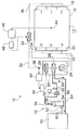
図1は、実施の形態の冷水の温度制御装置10が適用されたクリーンルーム用空調設備12の構造を示したブロック図である。同図に示すクリーンルーム14は、区画壁16によって外部と隔離され、室内には精密機械の製造ライン、検査解析装置などが設置される。このクリーンルーム14では、許容誤差±1/1000度オーダ以内で一定に温度が維持されることが要求される。
【0019】
区画壁16の壁面の図1上で右壁面には、空気供給パネル18が設けられるとともに、左壁面には空気吸気パネル20が設けられている。これらパネル18、20として、空気を通過させるとともに整流の作用もあるパンチングメタルが用いられている。
【0020】
吸気パネル20にはダクト22が接続されている。ダクト22には、送風機24、冷却コイル26、及び加熱器28からなる空調装置30が連結されている。また、この空調装置30の空気出口にはダクト32が接続され、これに空調用ヒータ34が接続されるとともにダクト36を介して供給パネル18が接続されている。このダクト配管により空調設備12は、クリーンルーム14内の空気を循環させる方式となっている。
【0021】
送風機24が作動されると、吸気パネル20からクリーンルーム14内の空気がダクト22を介して空調装置30に吸引される。吸引された前記空気は、冷却コイル26に接触して所定の温度まで冷却される。
【0022】
加熱器28は、内部にハロゲンランプを備えたランプヒータであり、この加熱器28の直後でダクト32内には温度センサ38が設けられ、加熱器28を出た直後のダクト32内の温度を検出している。温度センサ38は、デジタル調節計40に接続され、デジタル調節計40は、温度センサ38の温度情報に基づいてサイリスタ42を制御し、サイリスタ42によって、電源部(不図示)から加熱器28に所定の電圧の電力を供給する。なお、デジタル調節計40における分解能の性能としては±1/100度である。このような構成の加熱器28によって、冷却コイル26にて冷却された空気を、要求される温度の近傍まで加熱する。たとえば、要求温度が摂氏23.2度である場合には、加熱器28によって摂氏22.9度になるように空気を加熱制御する。
【0023】
クリーンルーム14内には、クリーンルーム14内の温度を検出する温度センサ44が設けられている。温度センサ44は、デジタル調節計46に接続され、デジタル調節計46は、温度センサ44の温度情報に基づいてサイリスタ48を制御し、サイリスタ48によって電源部(不図示)から空調用ヒータ34のランプヒータ(不図示)に所定の電圧の電力を供給する。ここで、デジタル調節計46における分解能は、デジタル調節計40よりも高いものが用いられ、クリーンルーム14における温度の±1/1000度まで可能なものが用いられる。
【0024】
かかる構造の空調設備12によって、供給パネル18から吹き出された空調空気は吸気パネル20から吸引されることにより、クリーンルーム14内でサイドフローとなって流れる。また、クリーンルーム14では厳しく温度が管理され、クリーンルーム14を摂氏23.2度で許容誤差1/1000度以内の温度で維持している。特に、クリーンルーム14におけるサイドフローによって、クリーンルーム14内に空気の滞留が生じず、クリーンルーム14内の温度分布が均等となり易く、乱流などの発生を防止できるので、温度制御性が向上する。
【0025】
また、空調装置30と空調用ヒータ34とを設け、これらを制御するための温度センサをダクトに取り付けることで、温度分解能の異なる2段階の温度制御を可能として、制御性の優れた空調設備12を提供できる。特に、空調装置30の加熱器28によって、要求される温度まで近づけておき、空調用ヒータ34によって、要求温度に維持させるので、加熱器28や空調用ヒータ34の制御熱量の変動が少なくなり、クリーンルーム14の室温の制御が行い易く、また室温の安定化も図れる。
【0026】
一方、実施の形態の冷水の温度制御装置10は、冷水製造装置50から供給される冷水を、冷水の自然の流れのなかで攪拌混合する冷水混合タンクである。以下、冷水の温度制御装置10を冷水混合タンク10と称する。
【0027】
この冷水混合タンク10は図1、図2に示すように、冷水製造装置50からの冷水が供給される供給口52が下部に形成された円筒状流路管54と、この円筒状流路管54の上端部に一体的に連結され上部に冷水の送出口56が形成された先細状の円錐状流路管58とによって構成されている。
【0028】
また、図1の如く、円筒状流路管54の供給口52には、第1の冷水供給管60を介して冷水製造装置50が接続され、円錐状流路管58の送出口56には、第2の冷水供給管62を介して冷却コイル26の入口部が接続されている。また、冷却コイル26の出口部は、冷水戻り管64を介して冷水製造装置50に接続されている。すなわち、実施の形態の空調設備12によれば、冷水製造装置50から冷水混合タンク10を介して冷却コイル26に至る冷水の循環系は1つであり、設備が簡素化されている。
【0029】
また、第2の冷水供給管62には、加熱器66及び温度センサ68が設けられている。更に、第1の冷水供給管60又は第2の冷水供給管62にはポンプ(不図示)が設けられ、このポンプによって冷水が前記循環系で循環される。
【0030】
加熱器66は、コイル状の伝熱ワイヤを有する電気ヒータであり、不図示の電源部から伝熱ワイヤに通電させることで伝熱ワイヤに熱を発生させ、ポンプによって搬送された冷水を伝熱ワイヤに接触させることで、所望の温度まで加熱する。また、温度センサ68は、加熱器66を通過した直後の冷水の温度を検出している。この温度センサ68は、デジタル調節計70に接続されており、デジタル調節計70は、温度センサ68の温度情報に基づいて加熱器66を制御する。
【0031】
次に、前記の如く構成された冷水混合タンク10の作用について説明する。
【0032】
冷水製造装置50から円筒状流路管54に供給された、温度にばらつきのある冷水は、図2の矢印の如く円筒状流路管54に流入した直後に、円筒状流路管54の下層部54Aにおいて急拡散する。これにより、冷水は、空間的に温度むらのある状態となるが、継続して供給されてくる冷水の水力によって円筒状流路管54内で自然に混合されることにより温度むらが徐々に少なくなっていく。そして、冷水は、円筒状流路管54の上層部54Bにおいて上昇流となって円錐状流路管58に導かれる。そして、円錐状流路管58を流れる際に、温度むらのあった冷水が、矢印の如く縮流していき空間的な温度むらが小さくなって平均化される。そして、円錐状流路管58の送出口56から、図1に示した第2の冷水供給管62に送り出される。
【0033】
このように、冷水混合タンク10は、円筒状流路管54において冷水を急拡散させ、この後、円錐状流路管58において冷水を縮流させる、という冷水の流れのなかで冷水の温度むらを平均化する構造なので、拡散装置を別途設けることなく、冷水の温度のばらつきを所定の範囲に抑えて、冷水を冷却コイル26に送り出すことができる。
【0034】
また、図3に示すように、円筒状流路管54の中層部に、多孔質の整流板72を設けることによって、円筒状流路管54から円錐状流路管58に流れる冷水を強制的に整流化できるので、円筒状流路管54において偏流が無くなり、冷水を均一に縮流・混合できる。これにより、温度制御性が向上する。
【0035】
実施の形態では、クリーンルーム用空調設備12の冷却コイル26に冷水を供給するための冷水の温度制御装置について説明したが、これに限定されるものではなく、本発明の冷水の温度制御装置は、加湿器、ウォータジャケットの温度制御装置にも適用できる。
【0036】
【実施例】
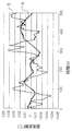
図4は、冷水製造装置50から供給された冷水の温度変動に対する、冷水混合タンク10から送出された冷水の温度変動状態を実験により取得して作成したグラフである。同図において、グラフAは、冷水混合タンク10から供給された冷水の温度変動を示したグラフ、グラフBは、冷水製造装置50から送出された冷水の温度変動を示したグラフである。
【0037】
また、図5のグラフCは、冷水製造装置50から供給された冷水の温度を加熱器66の電気ヒータのみで制御したときの温度変動を示したグラフ、グラフDは、冷水製造装置50から供給された冷水の温度を冷水混合タンク10と加熱器66の電気ヒータとで制御したときの温度変動を示したグラフである。なお、図4、図5のグラフの縦軸は温度変動を示し、横軸は経過時間を示している。
【0038】
図4のグラフBで示すように、冷水製造装置50から供給される生の冷水は、±0.04℃の範囲で大きく変動し、その変動周波数も高い。このような冷水を冷水混合タンク10に通すことなく冷却コイル26に直接供給すると、加熱器66の電気ヒータの特性により大きな変動には追従できないため、図5のグラフCに示すように、温度変化の大きい冷水が冷却コイルにそのまま供給される。このことは、クリーンルーム14の室温制御に悪影響を与える。
【0039】
これに対して、冷水製造装置50から供給される冷水を冷水混合タンク10に通すと、図4のグラフAの如く、高い周波数域の成分が均されるとともに、その温度ばらつきが±0.02℃の範囲に抑えられ、全体として温度むらが平均化された冷水となる。そして、冷水混合タンク10から出た冷水、すなわち温度むらが平均化された冷水を加熱器66によって更に制御することにより、図5のグラフDの如く、その温度ばらつきが±0.01℃の範囲に抑えられる。これは、低い周波数域の温度変化であれば温度制御可能な電気ヒータの特性による。
【0040】
以上により、実施の形態の冷水混合タンク10と加熱器66とを併用することにより、高精度な温度制御が可能となる。
【0041】
【発明の効果】
以上説明したように本発明に係る冷水の温度制御装置によれば、円筒状流路管において冷水を急拡散させ、この後、円錐状流路管において冷水を縮流させる、という冷水の流れのなかで冷水の温度むらを平均化する構造なので、拡散装置を別途設けることなく、冷水の温度のばらつきを所定の範囲に抑えて、冷水を送出することができる。
【0042】
また、円筒状流路管に整流部材を設けることによって、円筒状流路管から円錐状流路管に流れる冷水を整流化できるので、円筒状流路管において温度むらが小さくなった冷水を混合することなく円錐状流路管に導くことがで、温度制御性が向上する。
【0043】
また、本発明に係る空調設備によれば、冷水の循環系が1つで済むので、設備を簡素化できる。
【図面の簡単な説明】
【図1】 実施の形態の冷水の温度制御装置が適用されたクリーンルーム用空調設備の構造を示すブロック図
【図2】 実施の形態の冷水混合タンクの構造を示した縦断面図
【図3】 整流板を取り付けた冷水混合タンクの縦断面図
【図4】 冷水混合タンクを設けた場合の冷水温度変動状態を示したグラフ
【図5】 ヒータと冷水混合タンクを設けた場合の冷水温度変動状態を示したグラフ
【図6】 従来の空調設備の構造を示したブロック図
【符号の説明】
10…冷水の温度制御装置(冷水混合タンク)、12…クリーンルーム用空調設備、14…クリーンルーム、26…冷却コイル、30…空調装置、34…空調用ヒータ、50…冷水製造装置、52…供給口、54…円筒状流路管、56…送出口、58…円錐状流路管、60…第1の冷水供給管、62…第2の冷水供給管、64…冷水戻り管、66…加熱器、68…温度センサ、72…整流板[0001]
BACKGROUND OF THE INVENTION
The present invention relates to a cold water temperature control device and air conditioning equipment, and more particularly to a cold water temperature control device for controlling the temperature of cold water supplied to a cooling coil of a clean room air conditioning device and the air conditioning equipment therefor.
[0002]
[Prior art]
2. Description of the Related Art In recent years, a semiconductor manufacturing clean room has been required to strictly control the temperature in the room with the integration of semiconductors on a large scale. In particular, in a space in which inspection analysis work is actually performed, it is required to suppress room temperature fluctuations to ± 1/1000 degrees or less in order to increase inspection analysis accuracy. For this reason, highly accurate temperature management is implemented in the air conditioning equipment for clean rooms.
[0003]
By the way, a cooling coil for air cooling is provided in the air conditioning equipment. If the temperature of the chilled water supplied to the cooling coil fluctuates greatly, try to reheat it with the electric heater provided just before the cooling coil. However, due to the characteristics of the electric heater made of nichrome wire, it cannot follow large fluctuations. For this reason, there existed a problem that cold water with a large temperature change was supplied to the cooling coil as it was.
[0004]
Therefore, conventional air conditioning equipment temporarily stores chilled water supplied from the chilled water production apparatus to the cooling coil in a tank, and stirs and mixes the chilled water to supply the cooling coil with reduced cold water temperature unevenness. (For example, Non-Patent Document 1).
[0005]
[Non-Patent Document 1]
“Air Conditioning / Hygiene Engineering Vol. 65, No. 9” published by the Society for Air Conditioning and Sanitary Engineering, August 1991, p. 558
[0006]
[Problems to be solved by the invention]
However, the air conditioning equipment described in Non-Patent Document 1 has a drawback in that the running cost of the equipment increases because a stirring device must be provided in the tank in order to suppress the temperature unevenness of the cold water.
[0007]
By the way, the air-conditioning equipment which has a tank like a nonpatent literature 1 generally has the structure shown in FIG. The air-conditioning equipment shown in the figure includes a chilled water production apparatus 1, a
[0008]
The first cold water circulation system 4 includes an
[0009]
The amount of cold water flowing through the first cold water circulation system 4 is set to be larger than the amount of cold water flowing through the second cold
[0010]
This invention is made | formed in view of such a situation, and it aims at providing the temperature control apparatus of the cold water which can reduce a running cost with a simple structure.
[0011]
[Means for Solving the Problems]
The present invention, in order to achieve the above object, is supplied cold water with a variation in temperature, the temperature control device of the cold water to be sent by suppressing variation in the temperature of the cold water in a predetermined range, the cold water is supplied A cylindrical flow channel pipe having a supply port formed in the lower portion, and a tapered conical flow channel tube integrally connected to the upper end of the cylindrical flow channel tube and having the cold water delivery port formed in the upper portion; A temperature control apparatus for cold water having
[0012]
In order to achieve the above object, according to the present invention, a chilled water producing apparatus is connected to a supply port of the cylindrical flow channel pipe via a first cold water supply tube, and the outlet of the conical flow channel pipe In addition, an air conditioning facility is provided in which an inlet portion of a cooling coil is connected via a second cold water supply pipe, and the cold water producing apparatus is connected to an outlet portion of the cooling coil via a cold water return pipe.
[0013]
According to the temperature control device of the cold water of the present invention it was fed to a cylindrical flow pipe, cold water having variations in temperature, spatially temperature unevenness by rapidly diffused flow into the cylindrical flow pipe Although it is in a certain state, the unevenness of temperature gradually decreases due to the natural mixing in the cylindrical channel tube by the hydraulic power of the continuously supplied cold water . The cold water is led to the conical flow pipe as an upward flow through the cylindrical flow pipe, and the cold water with uneven temperature is contracted as it flows through the conical flow pipe. The average temperature unevenness is reduced and averaged. And it sends out outside from the delivery port of a conical channel pipe.
[0014]
Thus, the cold water temperature control system of the present invention is to suddenly spread cold water in cylindrical flow pipe, thereafter, the flow condensation of cold water in the conical flow pipe, cold water among the cold water flow that Since the temperature unevenness is averaged, it is possible to send out the cold water while suppressing the variation in the temperature of the cold water within a predetermined range without separately providing a diffusion device.
[0015]
In addition, by providing a rectifying member in the cylindrical channel pipe, the cold water flowing from the cylindrical channel pipe to the conical channel pipe can be rectified, so there is no uneven flow in the cylindrical channel pipe and the flow is uniform. Since mixing is possible, the effect of suppressing temperature unevenness is improved.
[0016]
Moreover, according to the air conditioning equipment which concerns on this invention, the cold water from a cold water manufacturing apparatus supplies the cylindrical flow-path pipe | tube of the temperature control apparatus of
[0017]
DETAILED DESCRIPTION OF THE INVENTION
Hereinafter, preferred embodiments of a cold water temperature control device and air conditioning equipment according to the present invention will be described in detail with reference to the accompanying drawings.
[0018]
FIG. 1 is a block diagram showing a structure of a clean room
[0019]
An
[0020]
A
[0021]
When the
[0022]
The
[0023]
A
[0024]
By the
[0025]
Further, by providing the
[0026]
On the other hand, the cold water
[0027]
As shown in FIGS. 1 and 2, the cold
[0028]
Further, as shown in FIG. 1, a cold
[0029]
The second cold
[0030]
The
[0031]
Next, the operation of the cold
[0032]
The cold water having a variation in temperature supplied from the cold
[0033]
As described above, the cold
[0034]
Further, as shown in FIG. 3, by providing a
[0035]
In the embodiment, the cold water temperature control device for supplying cold water to the cooling
[0036]
【Example】
FIG. 4 is a graph created by experimentally acquiring the temperature fluctuation state of the cold water sent from the cold
[0037]
A graph C in FIG. 5 shows a temperature variation when the temperature of the cold water supplied from the cold
[0038]
As shown in the graph B of FIG. 4, the raw cold water supplied from the cold
[0039]
On the other hand, when the chilled water supplied from the chilled
[0040]
As described above, by using the cold
[0041]
【The invention's effect】
According to the cold water temperature control apparatus according to the present invention described above, were suddenly spread cold water in cylindrical flow pipe, thereafter, the flow condensation of cold water in the conical flow pipe, the cold water flow that In particular, since the temperature unevenness of the chilled water is averaged, the chilled water can be sent out with a dispersion of the temperature of the chilled water within a predetermined range without providing a diffusion device.
[0042]
In addition, by providing a rectifying member in the cylindrical channel tube, the chilled water flowing from the cylindrical channel tube to the conical channel tube can be rectified, so that cold water with reduced temperature unevenness is mixed in the cylindrical channel tube. The temperature controllability is improved by guiding to the conical channel tube without doing so.
[0043]
In addition, according to the air conditioning equipment according to the present invention, since only one cold water circulation system is required, the equipment can be simplified.
[Brief description of the drawings]
FIG. 1 is a block diagram showing the structure of a clean room air conditioning system to which a cold water temperature control device according to an embodiment is applied. FIG. 2 is a longitudinal sectional view showing the structure of a cold water mixing tank according to the embodiment. Longitudinal section of a chilled water mixing tank with a rectifying plate [Fig. 4] A graph showing the chilled water temperature fluctuation state when a chilled water mixing tank is provided [Fig. [Figure 6] Block diagram showing the structure of a conventional air conditioning system [Explanation of symbols]
DESCRIPTION OF
Claims (3)
前記冷水が供給される供給口が下部に形成された円筒状流路管と、該円筒状流路管の上端部に一体的に連結され上部に前記冷水の送出口が形成された先細状の円錐状流路管とを有することを特徴とする冷水の温度制御装置。Temperature of variations cold water is supplied, in the temperature control apparatus for cold water sent by suppressing variation in the temperature of the cold water in a predetermined range,
Wherein the cold water-cylindrical channel tube supply port formed in the lower portion supplied, the cylindrical passage tube upper end integrally connected to the cold water outlet is tapered to be formed on top of the A cold water temperature control device comprising a conical channel tube.
Priority Applications (1)
| Application Number | Priority Date | Filing Date | Title |
|---|---|---|---|
| JP2003073360A JP4059112B2 (en) | 2003-03-18 | 2003-03-18 | Cold water temperature control device and air conditioning equipment |
Applications Claiming Priority (1)
| Application Number | Priority Date | Filing Date | Title |
|---|---|---|---|
| JP2003073360A JP4059112B2 (en) | 2003-03-18 | 2003-03-18 | Cold water temperature control device and air conditioning equipment |
Publications (2)
| Publication Number | Publication Date |
|---|---|
| JP2004278976A JP2004278976A (en) | 2004-10-07 |
| JP4059112B2 true JP4059112B2 (en) | 2008-03-12 |
Family
ID=33289275
Family Applications (1)
| Application Number | Title | Priority Date | Filing Date |
|---|---|---|---|
| JP2003073360A Expired - Lifetime JP4059112B2 (en) | 2003-03-18 | 2003-03-18 | Cold water temperature control device and air conditioning equipment |
Country Status (1)
| Country | Link |
|---|---|
| JP (1) | JP4059112B2 (en) |
Cited By (1)
| Publication number | Priority date | Publication date | Assignee | Title |
|---|---|---|---|---|
| WO2013080930A1 (en) * | 2011-12-02 | 2013-06-06 | Canon Kabushiki Kaisha | Temperature control system |
Families Citing this family (2)
| Publication number | Priority date | Publication date | Assignee | Title |
|---|---|---|---|---|
| JP4651377B2 (en) * | 2004-12-20 | 2011-03-16 | 株式会社テクノ菱和 | Air conditioning system |
| US8151579B2 (en) * | 2007-09-07 | 2012-04-10 | Duncan Scot M | Cooling recovery system and method |
-
2003
- 2003-03-18 JP JP2003073360A patent/JP4059112B2/en not_active Expired - Lifetime
Cited By (2)
| Publication number | Priority date | Publication date | Assignee | Title |
|---|---|---|---|---|
| WO2013080930A1 (en) * | 2011-12-02 | 2013-06-06 | Canon Kabushiki Kaisha | Temperature control system |
| JP2013117827A (en) * | 2011-12-02 | 2013-06-13 | Canon Inc | Temperature control device |
Also Published As
| Publication number | Publication date |
|---|---|
| JP2004278976A (en) | 2004-10-07 |
Similar Documents
| Publication | Publication Date | Title |
|---|---|---|
| US6295823B1 (en) | Apparatus and method for controlling temperature and humidity of a conditioned space | |
| US5976010A (en) | Energy efficient air quality maintenance system and method | |
| US6213867B1 (en) | Venturi type air distribution system | |
| US9612024B2 (en) | Energy efficient HVAC system | |
| US20110237175A1 (en) | Method device and system for heating/cooling and ventilating a premises | |
| US9920950B2 (en) | Chilled beam with multiple modes | |
| EP0243141A2 (en) | Heating apparatus | |
| US7410104B2 (en) | Heat source for radiant heating system | |
| CN1191292A (en) | Air conditioner | |
| US6623353B1 (en) | Venturi type air distribution system | |
| JP4059112B2 (en) | Cold water temperature control device and air conditioning equipment | |
| US11168895B2 (en) | Heating and hot-water supply apparatus | |
| JPH08285343A (en) | Air conditioner for clean room | |
| JPH0682362A (en) | Thermostat-humidistat | |
| JPH0682361A (en) | Thermostat-humidistat | |
| CN111425934A (en) | Air treatment device | |
| US7013969B1 (en) | Low noise level HVAC system having displacement with induction | |
| JP2009156510A (en) | Individual air conditioning device | |
| JP2006328687A (en) | Clean room and method of designing and constructing the same | |
| US20200309390A1 (en) | Air diffuser for localized climate control | |
| JPH01501335A (en) | Methods and devices for room air conditioning | |
| CN217383346U (en) | Water mixing and temperature adjusting system | |
| KR100509564B1 (en) | Heater for airconditioning | |
| RU2320937C1 (en) | Aerodynamic method of distribution of air flows in ventilation and air heating systems | |
| KR20220099276A (en) | Colling system for a room |
Legal Events
| Date | Code | Title | Description |
|---|---|---|---|
| A621 | Written request for application examination |
Free format text: JAPANESE INTERMEDIATE CODE: A621 Effective date: 20050311 |
|
| A977 | Report on retrieval |
Free format text: JAPANESE INTERMEDIATE CODE: A971007 Effective date: 20070815 |
|
| A131 | Notification of reasons for refusal |
Free format text: JAPANESE INTERMEDIATE CODE: A131 Effective date: 20070822 |
|
| A521 | Request for written amendment filed |
Free format text: JAPANESE INTERMEDIATE CODE: A523 Effective date: 20071016 |
|
| TRDD | Decision of grant or rejection written | ||
| A01 | Written decision to grant a patent or to grant a registration (utility model) |
Free format text: JAPANESE INTERMEDIATE CODE: A01 Effective date: 20071127 |
|
| A61 | First payment of annual fees (during grant procedure) |
Free format text: JAPANESE INTERMEDIATE CODE: A61 Effective date: 20071210 |
|
| FPAY | Renewal fee payment (event date is renewal date of database) |
Free format text: PAYMENT UNTIL: 20101228 Year of fee payment: 3 |
|
| R150 | Certificate of patent or registration of utility model |
Ref document number: 4059112 Country of ref document: JP Free format text: JAPANESE INTERMEDIATE CODE: R150 Free format text: JAPANESE INTERMEDIATE CODE: R150 |
|
| FPAY | Renewal fee payment (event date is renewal date of database) |
Free format text: PAYMENT UNTIL: 20101228 Year of fee payment: 3 |
|
| FPAY | Renewal fee payment (event date is renewal date of database) |
Free format text: PAYMENT UNTIL: 20111228 Year of fee payment: 4 |
|
| FPAY | Renewal fee payment (event date is renewal date of database) |
Free format text: PAYMENT UNTIL: 20111228 Year of fee payment: 4 |
|
| FPAY | Renewal fee payment (event date is renewal date of database) |
Free format text: PAYMENT UNTIL: 20121228 Year of fee payment: 5 |
|
| FPAY | Renewal fee payment (event date is renewal date of database) |
Free format text: PAYMENT UNTIL: 20131228 Year of fee payment: 6 |
|
| S111 | Request for change of ownership or part of ownership |
Free format text: JAPANESE INTERMEDIATE CODE: R313111 |
|
| R350 | Written notification of registration of transfer |
Free format text: JAPANESE INTERMEDIATE CODE: R350 |
|
| S111 | Request for change of ownership or part of ownership |
Free format text: JAPANESE INTERMEDIATE CODE: R313113 |
|
| R350 | Written notification of registration of transfer |
Free format text: JAPANESE INTERMEDIATE CODE: R350 |
|
| R250 | Receipt of annual fees |
Free format text: JAPANESE INTERMEDIATE CODE: R250 |
|
| R250 | Receipt of annual fees |
Free format text: JAPANESE INTERMEDIATE CODE: R250 |
|
| R250 | Receipt of annual fees |
Free format text: JAPANESE INTERMEDIATE CODE: R250 |
|
| EXPY | Cancellation because of completion of term |