JP4058905B2 - Location information setting method and apparatus for devices connected to network - Google Patents
Location information setting method and apparatus for devices connected to networkInfo
- Publication number
- JP4058905B2 JP4058905B2 JP2000392516A JP2000392516A JP4058905B2 JP 4058905 B2 JP4058905 B2 JP 4058905B2 JP 2000392516 A JP2000392516 A JP 2000392516A JP 2000392516 A JP2000392516 A JP 2000392516A JP 4058905 B2 JP4058905 B2 JP 4058905B2
- Authority
- JP
- Japan
- Prior art keywords
- recognition member
- position recognition
- information
- network
- identification information
- Prior art date
- Legal status (The legal status is an assumption and is not a legal conclusion. Google has not performed a legal analysis and makes no representation as to the accuracy of the status listed.)
- Expired - Fee Related
Links
- 238000000034 method Methods 0.000 title claims description 15
- 230000005540 biological transmission Effects 0.000 claims description 4
- 230000000694 effects Effects 0.000 claims description 3
- 238000010586 diagram Methods 0.000 description 6
- 238000012790 confirmation Methods 0.000 description 2
- 238000004891 communication Methods 0.000 description 1
- 238000009434 installation Methods 0.000 description 1
- 238000005259 measurement Methods 0.000 description 1
- 230000003287 optical effect Effects 0.000 description 1
- 238000005192 partition Methods 0.000 description 1
Images


Landscapes
- Length Measuring Devices By Optical Means (AREA)
- Computer And Data Communications (AREA)
- Small-Scale Networks (AREA)
Description
【0001】
【発明の属する技術分野】
本発明は、例えばフロア内に設置されている各種OA機器の位置情報を簡単に入力するための位置情報設定装置、位置情報設定システムに関する。
【0002】
【従来の技術】
最近では、LAN(ローカルエリアネットワーク)が構築され、コンピュータを用いて、ネットワークを介し各種OA機器を複数ユーザで共有したり、情報のやり取りなどを行うことができる環境が整い始めている。
【0003】
しかしながら、ユーザは、コンピュータ画面上でプリンタやスキャナ等の機器を選択して使用することはできるが、選択した機器の設置場所を知ることができないため、意図しない場所のスキャナを使用していたり、意図しない場所にプリント出力されてしまうという場合がある。
【0004】
この問題を解決するために、コンピュータ画面上に各機器の配置図を表示し、配置図中の機器を選択する技術(例えば、特開平10−177533号公報参照)が存在していた。
【0005】
【発明が解決しようとする課題】
しかしながら、配置図を作成するためにOA機器の管理者が、各OA機器の位置情報(例えば座標)をキーボード等から入力する必要があり、相当の手間を要していた。
【0006】
本発明の目的は、このような課題を解決するためのものであり、OA機器の位置情報を簡単に入力することができる位置情報設定装置、システムを提供することである。
【0007】
【課題を解決するための手段】
本発明の目的は、下記する手段により達成される。
【0008】
(1) ネットワークに接続されている機器の位置情報を設定するための位置情報設定装置において、所定の位置に設置された位置認識部材と、位置認識部材によって位置を認識される被位置認識部材とを有し、前記被位置認識部材は、ネットワークに接続されている前記機器に対し着脱可能な接続部と、前記位置認識部材が当該機器の識別情報を取得するための識別情報取得要求に応じて発光する発光手段とを備え、前記位置認識部材は、前記発光手段による発光に基づいて、前記被位置認識部材の位置を測定し位置情報を得る位置情報取得手段と、ネットワークに接続されている前記機器について、前記被位置認識部材の接続状態を示す接続情報を得るための接続情報取得要求を当該機器に対して送信して当該接続情報を得る接続情報取得手段と、ネットワークを介して、前記被位置認識部材が接続されている前記機器から、当該機器の前記識別情報を取得する識別情報取得手段とを備え、前記識別情報取得手段が取得した当該機器の前記識別情報と前記位置情報取得手段が得た前記位置情報とを対応付けて記憶することを特徴とする位置情報設定装置。
【0009】
(2) 前記機器は、前記被位置認識部材が接続されている旨をネットワークを介して前記位置情報認識部材に送信する送信部を有している(1)の位置情報設定装置。
【0011】
(3) 所定の位置に設置された位置認識部材と位置認識部材によって位置を認識される被位置認識部材とを用いた、ネットワークに接続されている機器の位置情報を設定するための位置情報設定方法において、前記位置認識部材が、ネットワークに接続されている前記機器について、前記被位置認識部材の接続状態を示す接続情報を得るための接続情報取得要求を当該機器に対して送信して当該接続情報を得る段階と、前記位置認識部材が、ネットワークを介して、前記被位置認識部材が接続されている前記機器から、当該機器の識別情報を取得する段階と、前記被位置認識部材が、前記位置認識部材が前記識別情報を取得するための識別情報取得要求に応じて発光する段階と、前記位置認識部材が、前記被位置認識部材の発光に基づいて当該被位置認識部材の位置を測定し位置情報を得る段階と、前記位置認識部材が、当該機器の前記識別情報と前記位置情報とを対応付けて記憶する段階と、を有することを特徴とする位置情報設定方法。
【0012】
【発明の実施の形態】
以下、本発明に係る実施形態を説明する。
【0013】
図1に示すように、本実施形態はフロアF上にネットワーク接続された各種OA機器30が設置されている。これらOA機器30は、例えばパーソナルコンピュータ、プリンタ、スキャナ、複写機、ファクシミリであり、ネットワークNを介して互いに情報のやり取りが可能となっている。ネットワークNは、有線によるものでも、無線によるものでもよい(Ethernet、Token Ring、Bluetooth、HomeRF等)。
【0014】
このようなフロアFに存在する各OA機器30の位置情報を認識するための、OA機器30に接続して用いられる被位置認識部材20と、被位置認識部材20の位置を認識するための位置認識部材10とが図中に示されている。
【0015】
本図において、被位置認識部材20は、ファクシミリに接続されており、位置認識部材10は、フロア内のパーティションボードや机などにより、被位置認識部材20の位置認識が妨げられないようフロアFの天井の中央部に固定的に取り付けられている。
【0016】
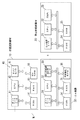
図2は、位置認識部材10、被位置認識部材20及びOA機器の内部構成を示すブロック図である。
【0017】
位置認識部材10は、ネットワークN上のOA機器30等との通信を行うためのネットワークインターフェース11、位置認識のためのプログラム等が記憶されているROM14、プログラムの実行、演算、各部制御等を行うCPU12、各種処理を実行するためのワーク領域となるRAM15、各種設定値などを記憶する不揮発性RAM16、及び、被位置認識部材20を認識するための認識部40とを有している。
【0018】
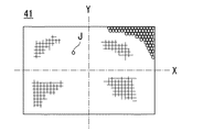
認識部40は、後述する被位置認識部材20が発光するレーザを検知するための受光部Jが複数個2次元に配置されたエリアセンサ41を有している(図3参照)。
【0019】
被位置認識部材20は、位置認識する対象となるOA機器30と接続するためのOA機器インターフェース21、プログラムの実行、演算、各部制御等を行うCPU22、位置認識のためのプログラム等が記憶されているROM24、各種処理を実行するためのワーク領域となるRAM25、所定の周波数のレーザを発する発光部23とを有している。
【0020】
OA機器インターフェース21は、被位置認識部材20の位置をOA機器30の位置として設定する理由から、被位置認識部材20とOA機器30とを接合あるいは隣接させる機能も有している。
【0021】
OA機器30は、位置認識部材10等との通信を行うためのネットワークインターフェース31、プログラムの実行、演算、各部制御等を行うCPU32、位置認識のためのプログラム等が記憶されているROM34、各種処理を実行するためのワーク領域となるRAM35、各種設定値などを記憶する不揮発性RAM36、OA機器インターフェース21に接続される被位置認識部材用インターフェース33とを有している。
【0022】
本実施形態においては、位置認識部材10で得られた位置情報は、ネットワークを介してOA機器30の不揮発性RAM36に記憶されるが、位置情報の記憶場所は、OA機器30の位置が管理できれば、位置認識部材10内、あるいはネットワーク上のサーバ50等に記憶してもよい。
【0023】
次に、位置認識部材10の認識部40の位置認識方法について図3を用いて説明する。
【0024】
前述したように、認識部40は、被位置認識部材20が発光するレーザを検知するための受光部Jが、複数個2次元に配置されたエリアセンサ41を有している。エリアセンサ41には、各受光部がフロアF上の各位置に対応するよう配置されており、どの受光部で被位置認識部材20からのレーザを受光したかを認識することにより、被位置認識部材20の位置情報を得ることができる。
【0025】
例えば、図1に示すように、被位置認識部材20がファクシミリに接合されている場合、フロアF全体をX−Y座標系の位置に対応したエリアセンサ41内の受光部Jでレーザを受光することになり、ファクシミリがフロアF内のどの位置に設置されているかが認識される。
【0026】
エリアセンサ41の形状は、フロアFの形状と必ずしも一致している必要はなく、受光部とフロアF上の位置関係が1対1であればどのような形状でもよい。
【0027】
このような場合には、エリアセンサ41の形状や光学系の影響による受光状態等に応じた受光位置をフロアF上の位置に換算するプログラムをあらかじめ位置認識部材10の不揮発性RAM16あるいはROM14に登録しておく必要がある。
【0028】
また、位置認識部材10の取り付け場所も天井の中央部に限らず、各OA機器が認識できる場所であればよい。
【0029】
次に本実施形態の位置認識手順を図4に基づいて説明する。
【0030】
まず、ユーザによって被位置認識部材20がOA機器30に接続(接合)されると(S10)、被位置認識部材20は、接続された旨をOA機器30に通知する(S12)。OA機器30は、接続状態にある旨を所定の情報としてRAM35に格納する(S14)。格納された接続状態を示す情報は、被位置認識手段20がOA機器30から切り離されるまで保持される。
【0031】
次に、位置認識部材10が位置認識動作開始に応じ(S16)、各OA機器30に被位置認識部材20が接続されているか問い合わせるために、ネットワークを介して各OA機器30に接続状態確認を要求する(S18)。
【0032】
接続確認要求を受けたOA機器30は、被位置認識部材20が接続されていれば、RAM35に格納されている接続状態を示す情報を位置認識部材10に対して返信し(S22、S24)、また、被位置認識部材20へ被位置認識部材20の識別IDの送信を要求する(S28)。識別IDは、OA機器と認識した被位置認識部材との関連付けに用いられるものである。
【0033】
識別ID送信要求を受信した被位置認識部材20は、識別IDをROM24から読み出し(S32)、OA機器30に返信する(S34)。識別IDは、OA機器30において、自己のOA機器情報(名称、種別等)と共にRAM35に格納される(S36)。
【0034】
一方、接続状態を示す情報を受信した位置認識部材10は、接続状態を示す情報と共に当該情報を送信したOA機器の宛先情報をRAM15に格納する(S26)。宛先情報は、ネットワーク上の識別情報であるIPアドレスなどである。
【0035】
次に、RAM15に格納された宛先情報に応じたOA機器30に対し、OA機器情報と識別IDの送信を要求する(S38、S40)。送信要求を受けたOA機器30は、RAM35に格納されているOA機器情報と識別IDを読み出し、位置認識部材10に返信した後(S42、S44、S46)、被位置認識部材20に対し位置認識開始を通知する(S50)。
【0036】
位置認識開始を通知された後、被位置認識部材20は、発光体23よりレーザを発する(S52)。位置認識部材10では、OA機器情報と識別IDをRAM25に記憶した後(S48)、レーザを受光したエリアセンサ41内の位置に応じて、被位置認識部材20のフロア上の位置を算出し(S54)、算出結果をOA機器30に送信する(S56)。
【0037】
OA機器30は、位置情報を不揮発性RAM36に格納し(S60)、被位置認識部材20に位置認識終了を通知する(S64)。位置認識終了を通知された被位置認識部材20は、レーザの発光を停止する(S66)。
【0038】
以上説明した位置認識手順は、1つの被位置認識部材20を複数のOA機器30に順次付け替えて各OA機器30の位置を認識しているが、OA機器30の台数が多い場合は、被位置認識部材20を複数用いて位置を認識してもよい。この場合には、各被位置認識部材20の識別ID毎にOA機器30の位置を認識するので、同時に複数OA機器30の位置認識が可能となり、位置情報設定作業のさらなる効率化を図ることができる。
【0039】
次に位置認識部材10の別の形態について図5〜7を用いて説明する。
【0040】
先述した位置認識部材10はフロア全体を視野とするものを説明したが、本形態は、位置認識部材10の認識部40′の視野はフロア全体より狭く、認識部40′自体の姿勢を変えてフロア全体を視野に入れるものである。
【0041】
認識部40′は、天井に取り付けるための支持台42と支持台42に対して回動可能な回転部43と回転部43の回転方向と垂直方向に90度回転可能なカメラ部44とからなる。回転部43とカメラ部44の回動によりカメラ部44からフロアF全域を見渡すことができる。
【0042】
このような認識部40′は、位置認識動作が開始されると、まず、認識部40′の真下から被位置認識部材20が発するレーザを探し出し、レーザが見つからなければ、次にカメラ部44を所定量回動させた後、回転部43を一回転させる。
【0043】
また、レーザが見つからなければ再度所定量カメラ部44を回動させた後、回転部43を一回転させる。レーザを見つけ、カメラ部44の視野のおよそ中心でレーザが検出されるまで、このような動作を繰り返す。
【0044】
回転部43、カメラ部44の回動量は、図示しないエンコーダの出力値に基づいて算出する。図6に示すようにカメラ部44の回動量を基準位置に対して角度α、回転部43の回動量を同様に角度βとすると、図7に示すように高さHはどのOA機器30においてもおよそ一定の値となることからあらかじめROM14に登録しておけば、角度α、角度βを用い、次式よりフロアF上の座標を算出することができる。
【0045】
y=Htanα
x=ytanβ
また、場合によっては、高さHが測定できないかあるいは既知の値でないこともあるが、この場合は、位置認識部材10から被位置認識部材20までの距離Lを測定してもよい。
【0046】
距離Lの測定は、例えば、カメラ部44の自動焦点機能を利用して測定してもよい。貝体的には、レンズの合焦位置から実際の距離Lを算出したり、赤外線や音波を発射して、その反射光や反射波が戻ってくるまでの時間から直接距離Lを測定する。
【0047】
角度α,β及び距離Lが測定されると、図7から明らかなように、位置認識部材10からOA機器30までの距離yが、y=Lsinαから算出でき、位置認識部材10からOA機器30までの距離xも、x=Lsinβから算出できることから、同様に被位置認識部材20の位置情報が取得できる。
【0048】
認識部40′のカメラ部44は、天井の中央部に取り付けられているが、場合によっては、天井の隅部などの他の適当な位置に配置してもよい。
【0049】
このように、認識部40′においては、カメラ部44を用い、カメラ部44の指向方向と、被位置認識部材20に関する距離とから被位置認識部材20の位置情報を取得する。したがって、前述した認識部40を用いる場合と同様、OA機器の位置を入力する必要がなく、利便性が向上する。しかも、1つの被位置認識部材20を用いて全てのOA機器の位置情報を取得できるので、コスト的に極めて有利となる。特に、認識部40′を用いる場合、個々のOA機器の位置情報がカメラ部44の動きにより直ちに入手できるので、測定誤差も少なく、より精度の高い位置情報の取得が可能となる。
【0050】
認識部40、40′は、室内全体を見渡しつつ被位置認識部材20の位置を測定しているが、各OA機器30の外形あるいは色等を視認できる識別手段を有するものでもよい。このような識別手段を有する認識部であれば、位置認識部材20に発光部23を設けることなく、例えばOA機器30の形状を予め画像パターンとして位置認識部材10に記憶しておき、記憶した画像パターンと一致する形状をしたOA機器30を被位置認識部材20と識別して、OA機器30の位置情報を直接取得し記憶することができる。
【0051】
前記位置認識部材10は、被位置認識部材20から発せられる入射光を直接感知するもののみでなく、反射光を感知するものでもよい。つまり、被位置認識部材20は、入射した方向と同じ方向に反射するプリズムを有する反射鏡などを備えていてもよい。このようにすれば、被位置認識部材20は、発光部23の代わりに反射鏡などを有していればよく、極めて構成を簡素化することができる。さらには、光の代わりに音波や電波を使用してもよい。
【0052】
前記実施形態では、1つのフロアF上でネットワークに接続されているOA機器30について述べたが、本発明は、これのみでなく複数フロアにわたってネットワークに接続されているOA機器30についても同様に使用できる。ただし、この場合は、各フロアの位置認識部材10をネットワークに接続する必要がある。
【0053】
【発明の効果】
以上説明したように、本発明によれば、ネットワークに接続されている機器の正確な位置情報を容易にかつ低コストで取得することができる。
【図面の簡単な説明】
【図1】 本発明の一実施形態を示す概略平面図である。
【図2】 同実施形態の位置認識部材、被位置認識部材及びOA機器の内部構成を示すブロック図である。
【図3】 エリアセンサを示す概略図である。
【図4】 同実施形態の動作説明図である。
【図5】 位置認識部材の別の形態を示す概略斜視図である。
【図6】 (A)は図5に示す位置認識部材のカメラ部が所定角度傾斜した状態の概略側面図、(B)は図5に示す位置認識部材の概略底面図である。
【図7】 図5に示す位置認識部材を用いた場合の位置認識部材、被位置認識部材及びOA機器の位置関係を示す説明図である。
【符号の説明】
10…位置認識部材、
14…ROM、
15…RAM、
20…被位置認識部材、
21…OA機器用インターフェース、
23…発光部、
24…ROM、
25…RAM、
30…OA機器、
34…ROM、
35…RAM、
36…不揮発性RAM、
40、40′…認識部、
N…ネットワーク。[0001]
BACKGROUND OF THE INVENTION
The present invention relates to a position information setting device and a position information setting system for easily inputting position information of various OA devices installed in a floor, for example.
[0002]
[Prior art]
Recently, a local area network (LAN) has been established, and an environment in which various users can share various OA devices and exchange information via a network using a computer has begun.
[0003]
However, although the user can select and use a device such as a printer or a scanner on the computer screen, the user cannot know the installation location of the selected device. In some cases, it is printed out at an unintended location.
[0004]
In order to solve this problem, there has been a technique (for example, see Japanese Patent Laid-Open No. 10-177533) that displays a layout diagram of each device on a computer screen and selects a device in the layout diagram.
[0005]
[Problems to be solved by the invention]
However, in order to create the layout drawing, it is necessary for the administrator of the OA device to input the position information (for example, coordinates) of each OA device from a keyboard or the like, which requires considerable effort.
[0006]
An object of the present invention is to solve such a problem, and is to provide a position information setting device and system capable of easily inputting position information of OA equipment.
[0007]
[Means for Solving the Problems]
The object of the present invention is achieved by the following means.
[0008]
(1) In a position information setting device for setting position information of a device connected to a network, a position recognition member installed at a predetermined position, and a position recognition member whose position is recognized by the position recognition member the a, the object position recognition member includes a connecting portion detachable with respect to the devices connected to the network, the location awareness member in response to the identification information acquisition request for acquiring the identification information of the device and a light emitting means for emitting light, the position recognition member, based on light emission by the light emitting means, the position information obtaining means for obtaining position information by measuring the position of the position recognition member, the connected to the network for devices, the connection information acquisition sending obtain the connection information the connection information acquisition request to obtain the connection information indicating the connection state of the object position recognition member relative to the apparatus Means, through the network, said from the devices to be the position recognition member is connected, and an identification information acquiring means for acquiring the identification information of the device, of the device in which the identification information acquisition unit acquires the identification information and position information setting device, characterized in that the position information acquisition means in association with said position information obtained.
[0009]
(2) the device, the position information setting apparatus has a transmission unit for transmitting the effect that the position recognition member is connected to said position information recognized member through a network (1).
[0011]
(3) Position information setting for setting position information of a device connected to a network using a position recognition member installed at a predetermined position and a position recognition member whose position is recognized by the position recognition member in the method, the position recognition member for the device connected to the network, the connection of the connection information acquisition request for obtaining connection information indicating the connection state of the object position recognition member is transmitted to the device a step of obtaining information, the position recognition member, via a network, said from the devices to be the position recognition member is connected, the method comprising: obtaining identification information of the device, the object position recognition member, the the method comprising position recognition member emits light in response to the identification information acquisition request for acquiring the identification information, the position recognition member, on the basis of the emission of the position recognition member those A step of obtaining position information by measuring the position of該被position recognition member, the position recognition member, and having a step of storing in association with the identification information and the positional information of the device, the Location information setting method.
[0012]
DETAILED DESCRIPTION OF THE INVENTION
Embodiments according to the present invention will be described below.
[0013]
As shown in FIG. 1, in this embodiment,
[0014]
The
[0015]
In this figure, the
[0016]
FIG. 2 is a block diagram showing the internal configuration of the
[0017]
The
[0018]
The
[0019]
The position-recognized
[0020]
The
[0021]
The
[0022]
In the present embodiment, the position information obtained by the
[0023]
Next, a position recognition method of the
[0024]
As described above, the recognizing
[0025]
For example, as shown in FIG. 1, when the
[0026]
The shape of the
[0027]
In such a case, a program for converting the light receiving position according to the shape of the
[0028]
Further, the location of the
[0029]
Next, the position recognition procedure of this embodiment is demonstrated based on FIG.
[0030]
First, when the position-recognized
[0031]
Next, in response to the start of the position recognition operation by the position recognition member 10 (S16), in order to inquire whether the
[0032]
When the
[0033]
The position-recognizing
[0034]
On the other hand, the
[0035]
Next, the
[0036]
After being notified of the start of position recognition, the position-recognized
[0037]
The
[0038]
The position recognition procedure described above recognizes the position of each
[0039]
Next, another form of the
[0040]
Although the above-described
[0041]
The
[0042]
When the position recognition operation is started, the recognizing
[0043]
If the laser is not found, the
[0044]
The amount of rotation of the
[0045]
y = Htanα
x = ytanβ
In some cases, the height H cannot be measured or is not a known value. In this case, the distance L from the
[0046]
The distance L may be measured using, for example, an autofocus function of the
[0047]
When the angles α and β and the distance L are measured, as is apparent from FIG. 7, the distance y from the
[0048]
The
[0049]
As described above, the
[0050]
The recognizing
[0051]
The
[0052]
In the above-described embodiment, the
[0053]
【The invention's effect】
As described above, according to the present invention, accurate position information of devices connected to a network can be acquired easily and at low cost.
[Brief description of the drawings]
FIG. 1 is a schematic plan view showing an embodiment of the present invention.
FIG. 2 is a block diagram showing an internal configuration of a position recognition member, a position recognition member, and an OA device according to the embodiment.
FIG. 3 is a schematic view showing an area sensor.
FIG. 4 is an operation explanatory diagram of the embodiment.
FIG. 5 is a schematic perspective view showing another form of the position recognition member.
6A is a schematic side view showing a state in which the camera unit of the position recognition member shown in FIG. 5 is tilted by a predetermined angle, and FIG. 6B is a schematic bottom view of the position recognition member shown in FIG.
7 is an explanatory diagram showing a positional relationship among a position recognition member, a position recognition member, and an OA device when the position recognition member shown in FIG. 5 is used.
[Explanation of symbols]
10 ... position recognition member,
14 ... ROM,
15 ... RAM,
20: Position recognition member,
21 ... OA equipment interface,
23 ... light emitting part,
24 ... ROM,
25 ... RAM,
30 ... OA equipment,
34 ... ROM,
35 ... RAM,
36 ... non-volatile RAM,
40, 40 '... recognizer,
N ... Network.
Claims (3)
所定の位置に設置された位置認識部材と、位置認識部材によって位置を認識される被位置認識部材とを有し、
前記被位置認識部材は、ネットワークに接続されている前記機器に対し着脱可能な接続部と、前記位置認識部材が当該機器の識別情報を取得するための識別情報取得要求に応じて発光する発光手段とを備え、
前記位置認識部材は、前記発光手段による発光に基づいて、前記被位置認識部材の位置を測定し位置情報を得る位置情報取得手段と、ネットワークに接続されている前記機器について、前記被位置認識部材の接続状態を示す接続情報を得るための接続情報取得要求を当該機器に対して送信して当該接続情報を得る接続情報取得手段と、ネットワークを介して、前記被位置認識部材が接続されている前記機器から、当該機器の前記識別情報を取得する識別情報取得手段とを備え、
前記識別情報取得手段が取得した当該機器の前記識別情報と前記位置情報取得手段が得た前記位置情報とを対応付けて記憶することを特徴とする位置情報設定装置。In the position information setting device for setting the position information of the devices connected to the network,
A position recognition member installed at a predetermined position; and a position recognition member whose position is recognized by the position recognition member;
The object position recognition member includes a connecting portion detachable with respect to the devices connected to the network, the light emitting means, wherein the position recognition member emits light in response to the identification information acquisition request for acquiring the identification information of the device And
The position recognition member, based on light emission by the light emitting means, the position information obtaining means for obtaining position information by measuring the position of the position recognition member, for the devices connected to the network, the object position recognition member and connection information acquiring unit that transmits to obtain the connection information the connection information acquisition request to obtain the connection information indicating the connection state with respect to the device, via the network, the object position recognition member is connected from the device, and an identification information acquiring means for acquiring the identification information of the device,
The identification information acquiring unit position information setting apparatus and to store in association with the acquired positional information to the identification information and the position information acquisition unit of the device is obtained.
前記位置認識部材が、ネットワークに接続されている前記機器について、前記被位置認識部材の接続状態を示す接続情報を得るための接続情報取得要求を当該機器に対して送信して当該接続情報を得る段階と、
前記位置認識部材が、ネットワークを介して、前記被位置認識部材が接続されている前記機器から、当該機器の識別情報を取得する段階と、
前記被位置認識部材が、前記位置認識部材が前記識別情報を取得するための識別情報取得要求に応じて発光する段階と、
前記位置認識部材が、前記被位置認識部材の発光に基づいて当該被位置認識部材の位置を測定し位置情報を得る段階と、
前記位置認識部材が、当該機器の前記識別情報と前記位置情報とを対応付けて記憶する段階と、
を有することを特徴とする位置情報設定方法。In a position information setting method for setting position information of a device connected to a network using a position recognition member installed at a predetermined position and a position recognition member whose position is recognized by the position recognition member,
The position recognition member for said device connected to a network, obtain the connection information the connection information acquisition request to obtain the connection information indicating the connection state of the object position recognition member is transmitted to the device Stages,
A step wherein the position recognition member, via a network, said from the devices to be the position recognition member is connected, for acquiring identification information of the device,
Wherein the method to be the position recognition member, said position recognition member emits light in response to the identification information acquisition request for acquiring the identification information,
The position recognition member, the step of obtaining the position measured position information of the object position recognition member based on the emission of the position recognition member,
The position recognition member, and storing in association with the identification information and the positional information of the device,
A position information setting method characterized by comprising:
Priority Applications (1)
| Application Number | Priority Date | Filing Date | Title |
|---|---|---|---|
| JP2000392516A JP4058905B2 (en) | 2000-12-25 | 2000-12-25 | Location information setting method and apparatus for devices connected to network |
Applications Claiming Priority (1)
| Application Number | Priority Date | Filing Date | Title |
|---|---|---|---|
| JP2000392516A JP4058905B2 (en) | 2000-12-25 | 2000-12-25 | Location information setting method and apparatus for devices connected to network |
Publications (2)
| Publication Number | Publication Date |
|---|---|
| JP2002196994A JP2002196994A (en) | 2002-07-12 |
| JP4058905B2 true JP4058905B2 (en) | 2008-03-12 |
Family
ID=18858494
Family Applications (1)
| Application Number | Title | Priority Date | Filing Date |
|---|---|---|---|
| JP2000392516A Expired - Fee Related JP4058905B2 (en) | 2000-12-25 | 2000-12-25 | Location information setting method and apparatus for devices connected to network |
Country Status (1)
| Country | Link |
|---|---|
| JP (1) | JP4058905B2 (en) |
Families Citing this family (2)
| Publication number | Priority date | Publication date | Assignee | Title |
|---|---|---|---|---|
| JP4595212B2 (en) * | 2001-02-20 | 2010-12-08 | コニカミノルタビジネステクノロジーズ株式会社 | POSITION INFORMATION SETTING DEVICE AND ENVIRONMENTAL INFORMATION ACQUIRING DEVICE |
| US8756308B2 (en) | 2008-03-31 | 2014-06-17 | Nec Display Solutions, Ltd. | Terminal, network apparatus, network apparatus searching system including the terminal and the network apparatus, and network apparatus searching method |
-
2000
- 2000-12-25 JP JP2000392516A patent/JP4058905B2/en not_active Expired - Fee Related
Also Published As
| Publication number | Publication date |
|---|---|
| JP2002196994A (en) | 2002-07-12 |
Similar Documents
| Publication | Publication Date | Title |
|---|---|---|
| US20110261405A1 (en) | Information processing terminal and power state management apparatus | |
| JP2016505839A (en) | Method and apparatus for determining position coordinates of a target | |
| JP2014238732A (en) | Self-propelled work device and program | |
| JP2007505299A (en) | Pixel | |
| JP2019152646A (en) | Survey system, survey method of survey system and attachment tool | |
| JP2023126497A (en) | Mobile object positioning device, mobile object positioning method and program | |
| JP2021077053A (en) | Map information providing system for autonomous moving device and autonomous moving device | |
| JP2013152224A (en) | Optical system | |
| CN106526538B (en) | A positioning base station, positioning system and positioning method | |
| JP4058905B2 (en) | Location information setting method and apparatus for devices connected to network | |
| JP7149506B2 (en) | Projection system, projection apparatus and projection method | |
| US20180069975A1 (en) | Information display system and image forming apparatus | |
| JP2020165658A (en) | 3D measurement method, 3D measurement device and robot system | |
| JP2019181783A (en) | Image forming apparatus and program | |
| WO2018095072A1 (en) | Positioning base station, positioning system, and positioning method | |
| JP2021034957A (en) | Projection system and projection method | |
| JP4595212B2 (en) | POSITION INFORMATION SETTING DEVICE AND ENVIRONMENTAL INFORMATION ACQUIRING DEVICE | |
| JP6766628B2 (en) | Information processing equipment, information processing systems, management servers and programs | |
| JP6264433B2 (en) | Work equipment | |
| JP2004348577A (en) | Information display system and pointing device control method in information display system | |
| EP3833017B1 (en) | Laser projector system | |
| CN111750800B (en) | Three-dimensional measuring device and robot system | |
| JPH08105721A (en) | Distance measuring method and device | |
| JPH07190773A (en) | Optical three-dimensional position detector | |
| WO2025120413A1 (en) | Light projection device, light projection-and-reception apparatus, and distance measurement system |
Legal Events
| Date | Code | Title | Description |
|---|---|---|---|
| A711 | Notification of change in applicant |
Free format text: JAPANESE INTERMEDIATE CODE: A712 Effective date: 20040423 |
|
| A621 | Written request for application examination |
Free format text: JAPANESE INTERMEDIATE CODE: A621 Effective date: 20050920 |
|
| RD03 | Notification of appointment of power of attorney |
Free format text: JAPANESE INTERMEDIATE CODE: A7423 Effective date: 20061011 |
|
| A131 | Notification of reasons for refusal |
Free format text: JAPANESE INTERMEDIATE CODE: A131 Effective date: 20070612 |
|
| A521 | Written amendment |
Free format text: JAPANESE INTERMEDIATE CODE: A523 Effective date: 20070810 |
|
| A131 | Notification of reasons for refusal |
Free format text: JAPANESE INTERMEDIATE CODE: A131 Effective date: 20070904 |
|
| A521 | Written amendment |
Free format text: JAPANESE INTERMEDIATE CODE: A523 Effective date: 20071101 |
|
| TRDD | Decision of grant or rejection written | ||
| A01 | Written decision to grant a patent or to grant a registration (utility model) |
Free format text: JAPANESE INTERMEDIATE CODE: A01 Effective date: 20071127 |
|
| A61 | First payment of annual fees (during grant procedure) |
Free format text: JAPANESE INTERMEDIATE CODE: A61 Effective date: 20071210 |
|
| FPAY | Renewal fee payment (event date is renewal date of database) |
Free format text: PAYMENT UNTIL: 20101228 Year of fee payment: 3 |
|
| R150 | Certificate of patent or registration of utility model |
Free format text: JAPANESE INTERMEDIATE CODE: R150 |
|
| FPAY | Renewal fee payment (event date is renewal date of database) |
Free format text: PAYMENT UNTIL: 20111228 Year of fee payment: 4 |
|
| FPAY | Renewal fee payment (event date is renewal date of database) |
Free format text: PAYMENT UNTIL: 20121228 Year of fee payment: 5 |
|
| FPAY | Renewal fee payment (event date is renewal date of database) |
Free format text: PAYMENT UNTIL: 20131228 Year of fee payment: 6 |
|
| S111 | Request for change of ownership or part of ownership |
Free format text: JAPANESE INTERMEDIATE CODE: R313111 |
|
| R350 | Written notification of registration of transfer |
Free format text: JAPANESE INTERMEDIATE CODE: R350 |
|
| LAPS | Cancellation because of no payment of annual fees |