JP4058636B2 - Joints between simple building beams and roof panels - Google Patents
Joints between simple building beams and roof panels Download PDFInfo
- Publication number
- JP4058636B2 JP4058636B2 JP2003361959A JP2003361959A JP4058636B2 JP 4058636 B2 JP4058636 B2 JP 4058636B2 JP 2003361959 A JP2003361959 A JP 2003361959A JP 2003361959 A JP2003361959 A JP 2003361959A JP 4058636 B2 JP4058636 B2 JP 4058636B2
- Authority
- JP
- Japan
- Prior art keywords
- cross member
- fixed
- roof panel
- simple building
- longitudinal direction
- Prior art date
- Legal status (The legal status is an assumption and is not a legal conclusion. Google has not performed a legal analysis and makes no representation as to the accuracy of the status listed.)
- Expired - Fee Related
Links
- 239000000463 material Substances 0.000 claims description 10
- 230000000694 effects Effects 0.000 description 4
- 230000008878 coupling Effects 0.000 description 3
- 238000010168 coupling process Methods 0.000 description 3
- 238000005859 coupling reaction Methods 0.000 description 3
- 238000009434 installation Methods 0.000 description 2
- 229910001220 stainless steel Inorganic materials 0.000 description 2
- 238000005452 bending Methods 0.000 description 1
- 230000003247 decreasing effect Effects 0.000 description 1
- 230000004048 modification Effects 0.000 description 1
- 238000012986 modification Methods 0.000 description 1
- 230000003014 reinforcing effect Effects 0.000 description 1
- 239000010935 stainless steel Substances 0.000 description 1
- XLYOFNOQVPJJNP-UHFFFAOYSA-N water Substances O XLYOFNOQVPJJNP-UHFFFAOYSA-N 0.000 description 1
Images
Landscapes
- Joining Of Building Structures In Genera (AREA)
Description
本発明は、例えばカーポートなどの簡易建物の梁と屋根パネルとを連結する連結具に関するものである。 The present invention relates to a connector for connecting a beam of a simple building such as a carport and a roof panel.
従来、上記した簡易建物の梁と屋根パネルとの連結具として、例えば特許文献1の如く、柱と柱から片持梁を形成し弦材を用いてトラス構造を形成することによって屋根部材を片流れに支持するものが知られている。また、特許文献2の如く屋根パネルを梁の長手方向の任意の位置に固定できるように設けて柱の立設位置の自由度を高めたものなども開示されている。
ところが、上記した従来の簡易建物の梁と屋根パネルとを連結する連結具はいずれも柱を少なくとも2本以上立設して梁材、横材を連結し、屋根パネルを支持するようにしたものであり、特に柱が1本しか立設できないような狭小地等に適用しようとすると屋根パネルが不安定となり、風に煽られて回転したり、強固に安定して支持することができないという問題があり、こうした問題を解決することが従来の課題となっていた。 However, all of the above-mentioned conventional connecting tools for connecting beams and roof panels of a simple building are constructed by supporting at least two columns and connecting beams and cross members to support the roof panel. In particular, if it is applied to a narrow area where only one pillar can stand, the roof panel becomes unstable and cannot be rotated by the wind or cannot be supported firmly and stably. There has been a conventional problem to solve these problems.
そこで本発明は、狭小地にも対応できるように1本の柱・梁だけで安定に設置することが可能な簡易建物の梁と屋根パネルとの連結具を提供することを目的としている。 SUMMARY OF THE INVENTION An object of the present invention is to provide a simple building beam and roof panel connector that can be stably installed with only one column / beam so that it can be applied to a narrow area.
本発明の請求項1に係わる連結具は、横材と左斜め部材と右斜め部材と連結材とを備え、横材は前後方向に延びる梁の下方に梁と直交して左右方向に延びるとともに、屋根パネルの上面に固定してあり、左斜め部材は梁の左側面と横材の左側上面との間に固定してあり、右斜め部材は梁の右側面と横材の右側上面との間に固定してあり、連結材は梁の下面と横材の側面との間に固定してある構成を前述した従来の課題を解決するための手段としている。
The connector according to
本発明の請求項2に係わる簡易建物の梁と屋根パネルとの連結具は、上記した請求項1の構成に加えて、左右の斜め部材及び連結材は、梁の長手方向にスライド自在に係止して梁への取付位置を前後方向に変更自在にしてあるとともに、横材の長手方向にスライド自在に係止して横材への取付位置を左右方向に変更自在にしてある構成としている。 In addition to the structure of the first aspect described above, the connecting tool for a simple building beam and roof panel according to claim 2 of the present invention is such that the left and right diagonal members and the connecting member are slidable in the longitudinal direction of the beam. The mounting position on the beam is freely changeable in the front-rear direction, and is slidably locked in the longitudinal direction of the cross member so that the attachment position on the cross member can be changed in the left-right direction. .
本発明の請求項1に係わる簡易建物の梁と屋根パネルとの連結具において、連結材は梁の下面に固定して梁と連結材とで1辺を形成しており、且つ、連結材は横材の側面にも固定してあり、そして左右の斜め部材はそれぞれ梁の左右の側面と横材の左右の上面との間に固定してあるから、梁と連結材と横材と左右の斜め部材とで梁の左右方向に二つのトラス構造を形成していることとなるから横材は梁に強固に連結固定されることとなり、且つ、横材は屋根パネルの上面に固定してあるものであるから、1本の柱・梁だけであっても屋根パネルを強固に固定することができるという格別の効果が得られるものである。
In the connection device between a beam and a roof panel of a simple building according to
本発明の請求項2に係わる簡易建物の梁と屋根パネルとの連結具において、上記した構成としたので請求項1の効果に加えて、屋根パネルの取付位置を前後左右に変更が自在であるから、特に狭小地等に設置する場合に設置場所の状況に合わせて容易に屋根の位置を調整変更することが可能であるという大きな効果が得られる。
In the connecting device between the beam and the roof panel of the simple building according to claim 2 of the present invention, since it is configured as described above, in addition to the effect of
本発明において簡易建物とはカーポート、サイクルポート、通路シェルター、エントランススペース等に適用される柱、梁と屋根パネルとで構成した建物である。 In the present invention, a simple building is a building composed of columns, beams and roof panels applied to carports, cycle ports, passage shelters, entrance spaces and the like.
以下、本発明を図面に基づいて説明する。 Hereinafter, the present invention will be described with reference to the drawings.
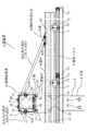
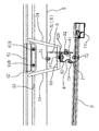
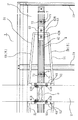
図1〜図3は本発明に係わる簡易建物の梁と屋根パネルとの連結具の第一実施形態を示しており、図4は第一実施形態の梁2と屋根パネルPとの連結具1を適用した簡易建物Sの全体像を三面図で表わしている。図3は図4のA部を拡大した平面図であり、図1は図3の正面断面図、図2は図3の右側面図である。
FIGS. 1 to 3 show a first embodiment of a connecting member between a beam and a roof panel of a simple building according to the present invention, and FIG. 4 shows a connecting
図4に示す如く、本発明の第一実施形態の梁2と屋根パネルPとの連結具1を適用した簡易建物Sは地中に基礎を設けて立設した1本の支柱8の上端部に前方に突出するように1本の梁2を固定してあり、梁2の前後2ヶ所に本発明の連結具1を適用して横材4の下方に屋根パネルPを取り付け固定しているものである。図1に示す如く支柱8と梁2との連結部は補強材9及び支柱固定ボルト91、梁固定ボルト92を用いて強固に固定してある。
As shown in FIG. 4, the simple building S to which the
以下に、本発明の簡易建物の梁と屋根パネルとの連結具1の詳細について、図1〜図3で説明する。連結具1は前後方向に延びる梁2と、梁2の下方に梁2と直交する左右方向に延びる横材4と、梁2の下面にねじ止め固定するとともに横材4の長手方向側面をねじ止め固定する連結材3と、梁2の左側面と横材4の左側上面との間に固定する左斜め部材5Lと、梁2の右側面と横材4の右側上面との間に固定する右斜め部材5Rとを備え、左斜め部材5Lと連結材3と横材4の左側上面とが梁2の左側面とで左側のトラスを形成し、右斜め部材5Rと連結材3と横材4の右側上面とが梁2の右側面とで右側のトラスを形成しているものである。尚、第一実施形態の連結具1の左右の斜め部材5、5(5R、5L)および、上記した如く形成される左右のトラスはいずれも左右対称に設けてあるので、以下の説明では左側について省略し、右側の構成のみについて詳細に説明する。
Below, the detail of the
図2及び図3に示す如く、斜め部材5(5R)はステンレス線材製の略V字状(台形)を為す部材であり、略V字の底にあたる部分(台形の短辺側)を横材側係合部53として横材4の右側上面に当接し、横材側固定具62を冠せて、横材側固定具62を横材4の上方に横材4の長手方向に設けた固定具固定ボルト係合溝42に係合する固定ボルト62Bでねじ止め固定することによって横材側係合部53を横材4に当接固定してある。そして、略V字の二つの頂部間は連結してあって台形の長辺を形成してあり、これを梁側係合部52として梁2の右側面に当接するとともに、梁側固定具61を側方から冠せて梁側固定具61の上部を梁2の右上端長手方向に設けた固定具係合溝21に挿入係合せしめ、そして梁側固定具61の下部を梁2の右側面に長手方向に設けた梁側固定ボルト係合溝22に係合する固定ボルト61Bで梁2に側方からねじ止め固定することによって梁側係合部52を梁2の右側面に当接固定してある。また、図1及び図2に示す如く、連結材3はステンレス板材を略L字状に折り曲げ成形した部材であり、折り曲げたコーナー部を梁2の下面に当接するとともに横材4の長手方向に沿う方向に配置し、略L字の一辺を梁2の下面に長手方向に設けた連結材固定ボルト係合溝23に係合する梁固定ボルト31で梁2の下面にねじ止め固定するとともに略L字の他辺を横材4の側面に当接するとともに横材4の長手方向に設けた横材固定ボルト係合溝41に係合する横材固定ボルト32で横材4をねじ止め固定してある。
As shown in FIGS. 2 and 3, the diagonal member 5 (5R) is a member made of stainless steel wire and has a substantially V-shape (trapezoid), and the portion corresponding to the bottom of the substantially V-shape (the trapezoid short side) is a cross member. The
本発明の第一実施形態の連結具1は上記の通りの構成としてあるので、梁固定ボルト31でねじ止め固定した連結材3と梁2とを一辺と為し、これと横材4と斜め部材5の弦部51とを他の二辺と為してそれぞれねじ止め固定してあることによって、これらはトラスを形成することとなり、そして、上記した通り斜め部材5は略V字状を為して底部に当たる横材側係合部53を横材4の右側上面に固定してあるとともに二つの頂部に当たる梁側係合部52を梁2に固定してあるから、二つの弦部51、51を有する斜め部材5の略V字の底部、即ち横材側係合部53と略V字の二つの頂部、即ち梁側係合部52の両端部と、梁2の底面に固定した連結材3と横材4とを横材固定ボルト32で連結固定している固定部との4つのポイントは丁度三角錐体の4つの頂点を為しており、即ち、三つのトラスの集合体となるトラス構造体を形成していることとなり、従って、このトラス構造体の二つの辺を為す梁2と横材4とは互いに捩れ方向の力を受けてもこれに十分耐えうる強固な結合構造を形成していることとなるものである。
Since the
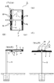
本発明の第一実施形態の連結具1を適用した簡易建物Sは、上記した通り梁2に横材4を強固に固定して設けた連結具1を利用するものであり、本実施例においては梁2の前後2ヶ所に固定した横材4の下部に屋根パネルPを固定することによって形成したものである。更に詳しく説明すれば、梁2の前方に用いる連結具1は梁2の下面に取り付ける連結材3の梁2への当接面から横材固定ボルト32までの長さを梁2の後方に用いる連結具1のそれよりも短くして屋根パネルPに水勾配を設けるようにしてあり、屋根パネルPは枠材73、73、・・で枠組みしたものであって、横材4の下方に固定ねじ71でねじ止め固定したパネル固定具7にパネル固定ねじ72で屋根パネルPをねじ止め固定しているものである。
The simple building S to which the
先に説明した通り、本発明の第一実施形態の簡易建物の梁と屋根パネルとの連結具1において、斜め部材5の梁側係合部52を固定している梁側固定具61は上部を梁2の右上端長手方向に設けた固定具係合溝21に挿入係合せしめ、下部を梁側固定ボルト係合溝22に係合する固定ボルト61Bで梁2にねじ止め固定しているものであるから梁2の長手方向に摺動自在であり、また、連結材3を梁2に固定している梁固定ボルト31は梁2の下面に長手方向に設けた連結材固定ボルト係合溝23に係合するものであるから、やはり梁2の長手方向に摺動自在であり、従って、斜め部材5と連結材3とで固定してある横材4は梁2に沿って摺動することによって梁2の長手方向に位置調整自在であり、よって、横材4で支持している屋根パネルPを梁2の長手方向、即ち図4の側面図に矢印で示した如く屋根パネルPの前後方向に位置調整自在としていることとなる。そして、横材4を一方の上面で固定する横材側固定具62は横材4の上方に横材4の長手方向に設けた固定具固定ボルト係合溝42に係合する固定ボルト62Bでねじ止め固定したものであるから、横材4は横材側固定具62及び斜め部材5に対して横材4の長手方向に摺動自在であり、また、横材4を梁2の下方で連結材3に固定している横材固定ボルト32は横材4の長手方向に設けた横材固定ボルト係合溝41に係合するものであるから、横材4は連結材3及び梁2に対して横材4の長手方向に摺動自在である。従って、横材4は斜め部材5に対しても梁2に対しても横材4の長手方向に摺動自在であるから、横材4で支持している屋根パネルPを横材4の長手方向、即ち図4の背面図に矢印で示した如く屋根パネルPの左右方向に位置調整自在としていることとなるものである。従って、本発明の第一実施形態の簡易建物Sの梁2と屋根パネルPとの連結具1は屋根パネルPの取り付け位置を必要に応じて前後左右に調整自在としているので、簡易建物Sの設置場所の状況に応じて屋根パネルPの位置を調整することができるという格別の効果を有するものである。
As described above, in the connecting
本発明は、上述した実施の形態に限定されるものではなく、本発明の趣旨を逸脱しない範囲で種々の変更が可能である。例えば、支柱は1本のみで立設した場合を例示したが、複数の支柱を立設して設けた簡易建物に適用することも可能である。また、1本の梁に固定する横材の数は適宜増減しても良い。 The present invention is not limited to the embodiments described above, and various modifications can be made without departing from the spirit of the present invention. For example, although the case where only one column is erected is illustrated, it can be applied to a simple building in which a plurality of columns are erected. Further, the number of cross members fixed to one beam may be appropriately increased or decreased.
1 連結具
2 梁
3 連結材
4 横材
5 斜め部材
5R 右斜め部材
5L 左斜め部材
61 梁側固定具
62 横材側固定具
8 支柱
S 簡易建物
P 屋根パネル
DESCRIPTION OF
Claims (2)
Priority Applications (1)
| Application Number | Priority Date | Filing Date | Title |
|---|---|---|---|
| JP2003361959A JP4058636B2 (en) | 2003-03-28 | 2003-10-22 | Joints between simple building beams and roof panels |
Applications Claiming Priority (2)
| Application Number | Priority Date | Filing Date | Title |
|---|---|---|---|
| JP2003091764 | 2003-03-28 | ||
| JP2003361959A JP4058636B2 (en) | 2003-03-28 | 2003-10-22 | Joints between simple building beams and roof panels |
Publications (2)
| Publication Number | Publication Date |
|---|---|
| JP2004316408A JP2004316408A (en) | 2004-11-11 |
| JP4058636B2 true JP4058636B2 (en) | 2008-03-12 |
Family
ID=33478529
Family Applications (1)
| Application Number | Title | Priority Date | Filing Date |
|---|---|---|---|
| JP2003361959A Expired - Fee Related JP4058636B2 (en) | 2003-03-28 | 2003-10-22 | Joints between simple building beams and roof panels |
Country Status (1)
| Country | Link |
|---|---|
| JP (1) | JP4058636B2 (en) |
Cited By (1)
| Publication number | Priority date | Publication date | Assignee | Title |
|---|---|---|---|---|
| CN106285114A (en) * | 2016-01-29 | 2017-01-04 | 傅婉娜 | Steel cable promotes the multi-storied garage of a chassis |
Families Citing this family (1)
| Publication number | Priority date | Publication date | Assignee | Title |
|---|---|---|---|---|
| JP5530377B2 (en) * | 2011-02-23 | 2014-06-25 | 三協立山株式会社 | Assembly building |
-
2003
- 2003-10-22 JP JP2003361959A patent/JP4058636B2/en not_active Expired - Fee Related
Cited By (1)
| Publication number | Priority date | Publication date | Assignee | Title |
|---|---|---|---|---|
| CN106285114A (en) * | 2016-01-29 | 2017-01-04 | 傅婉娜 | Steel cable promotes the multi-storied garage of a chassis |
Also Published As
| Publication number | Publication date |
|---|---|
| JP2004316408A (en) | 2004-11-11 |
Similar Documents
| Publication | Publication Date | Title |
|---|---|---|
| WO2019044632A1 (en) | Roof structure and construction method for same | |
| JP4029816B2 (en) | Simple structure | |
| JP4058636B2 (en) | Joints between simple building beams and roof panels | |
| JP2009197437A (en) | Truss structure | |
| JP3963222B2 (en) | Assembled structure of bracing frames used for steel frame structures | |
| JP7188094B2 (en) | roof structure | |
| JP3828641B2 (en) | Column and beam connection structure | |
| JP2009287319A (en) | Connecting tool | |
| JP2000104342A (en) | Load-bearing structure of wooden buildings | |
| JP3276299B2 (en) | Reinforcement hardware for wooden buildings | |
| JP3721508B2 (en) | building | |
| JP2696478B2 (en) | Roof structure and its construction method | |
| JP2011012412A (en) | Building material reinforcing implement and method for constructing building structure | |
| KR20060073013A (en) | Joining member for steel structure with damper function | |
| KR20190091791A (en) | Jointing Apparatus for preventing earthquake | |
| JP3268191B2 (en) | Construction method of rigid floor structure | |
| JP2750107B2 (en) | Hut structure | |
| JP2893321B2 (en) | Assembly buildings such as approaches | |
| JP2895815B2 (en) | Floor panel mounting structure | |
| JP2003020727A (en) | Roof structure of unit house | |
| JP2004150161A (en) | Compressed member for scaffold, connecting structure of scaffold and connecting method | |
| JP2005232839A (en) | Building structure and fabricated building | |
| JP2006161322A (en) | Seismic reinforcing fitting for wooden building | |
| JP2002371674A (en) | Construction method of arched curved roof | |
| JP3623208B2 (en) | Reinforcement hardware in wooden buildings and wooden frame structures using the same |
Legal Events
| Date | Code | Title | Description |
|---|---|---|---|
| A621 | Written request for application examination |
Free format text: JAPANESE INTERMEDIATE CODE: A621 Effective date: 20050926 |
|
| A977 | Report on retrieval |
Free format text: JAPANESE INTERMEDIATE CODE: A971007 Effective date: 20070531 |
|
| TRDD | Decision of grant or rejection written | ||
| A01 | Written decision to grant a patent or to grant a registration (utility model) |
Free format text: JAPANESE INTERMEDIATE CODE: A01 Effective date: 20071121 |
|
| A61 | First payment of annual fees (during grant procedure) |
Free format text: JAPANESE INTERMEDIATE CODE: A61 Effective date: 20071204 |
|
| FPAY | Renewal fee payment (event date is renewal date of database) |
Free format text: PAYMENT UNTIL: 20101228 Year of fee payment: 3 |
|
| R150 | Certificate of patent or registration of utility model |
Ref document number: 4058636 Country of ref document: JP Free format text: JAPANESE INTERMEDIATE CODE: R150 Free format text: JAPANESE INTERMEDIATE CODE: R150 |
|
| FPAY | Renewal fee payment (event date is renewal date of database) |
Free format text: PAYMENT UNTIL: 20101228 Year of fee payment: 3 |
|
| FPAY | Renewal fee payment (event date is renewal date of database) |
Free format text: PAYMENT UNTIL: 20111228 Year of fee payment: 4 |
|
| FPAY | Renewal fee payment (event date is renewal date of database) |
Free format text: PAYMENT UNTIL: 20121228 Year of fee payment: 5 |
|
| FPAY | Renewal fee payment (event date is renewal date of database) |
Free format text: PAYMENT UNTIL: 20131228 Year of fee payment: 6 |
|
| FPAY | Renewal fee payment (event date is renewal date of database) |
Free format text: PAYMENT UNTIL: 20131228 Year of fee payment: 6 |
|
| S533 | Written request for registration of change of name |
Free format text: JAPANESE INTERMEDIATE CODE: R313533 |
|
| FPAY | Renewal fee payment (event date is renewal date of database) |
Free format text: PAYMENT UNTIL: 20131228 Year of fee payment: 6 |
|
| R350 | Written notification of registration of transfer |
Free format text: JAPANESE INTERMEDIATE CODE: R350 |
|
| LAPS | Cancellation because of no payment of annual fees |