JP4058626B2 - Optical fiber fusion splicing method and optical fiber - Google Patents
Optical fiber fusion splicing method and optical fiber Download PDFInfo
- Publication number
- JP4058626B2 JP4058626B2 JP2003024003A JP2003024003A JP4058626B2 JP 4058626 B2 JP4058626 B2 JP 4058626B2 JP 2003024003 A JP2003024003 A JP 2003024003A JP 2003024003 A JP2003024003 A JP 2003024003A JP 4058626 B2 JP4058626 B2 JP 4058626B2
- Authority
- JP
- Japan
- Prior art keywords
- coating
- optical fiber
- mold
- resin
- tensile
- Prior art date
- Legal status (The legal status is an assumption and is not a legal conclusion. Google has not performed a legal analysis and makes no representation as to the accuracy of the status listed.)
- Expired - Fee Related
Links
- 239000013307 optical fiber Substances 0.000 title claims description 72
- 238000000034 method Methods 0.000 title claims description 14
- 238000007526 fusion splicing Methods 0.000 title description 13
- 238000000576 coating method Methods 0.000 claims description 111
- 239000011248 coating agent Substances 0.000 claims description 106
- 239000011347 resin Substances 0.000 claims description 71
- 229920005989 resin Polymers 0.000 claims description 71
- 230000004927 fusion Effects 0.000 claims description 17
- 239000000835 fiber Substances 0.000 claims description 16
- 239000000853 adhesive Substances 0.000 claims description 11
- 230000001070 adhesive effect Effects 0.000 claims description 11
- 239000011342 resin composition Substances 0.000 claims description 10
- LFQSCWFLJHTTHZ-UHFFFAOYSA-N Ethanol Chemical compound CCO LFQSCWFLJHTTHZ-UHFFFAOYSA-N 0.000 description 34
- 238000012216 screening Methods 0.000 description 10
- UHESRSKEBRADOO-UHFFFAOYSA-N ethyl carbamate;prop-2-enoic acid Chemical compound OC(=O)C=C.CCOC(N)=O UHESRSKEBRADOO-UHFFFAOYSA-N 0.000 description 5
- 239000000203 mixture Substances 0.000 description 5
- CSCPPACGZOOCGX-UHFFFAOYSA-N Acetone Chemical compound CC(C)=O CSCPPACGZOOCGX-UHFFFAOYSA-N 0.000 description 4
- 239000011521 glass Substances 0.000 description 4
- 239000007788 liquid Substances 0.000 description 4
- 238000005259 measurement Methods 0.000 description 4
- 229910001507 metal halide Inorganic materials 0.000 description 3
- 150000005309 metal halides Chemical class 0.000 description 3
- 238000012360 testing method Methods 0.000 description 3
- QAOWNCQODCNURD-UHFFFAOYSA-N Sulfuric acid Chemical compound OS(O)(=O)=O QAOWNCQODCNURD-UHFFFAOYSA-N 0.000 description 2
- 239000012298 atmosphere Substances 0.000 description 2
- 239000003365 glass fiber Substances 0.000 description 2
- 230000005484 gravity Effects 0.000 description 2
- 230000001678 irradiating effect Effects 0.000 description 2
- 238000002156 mixing Methods 0.000 description 2
- 239000000178 monomer Substances 0.000 description 2
- 230000003287 optical effect Effects 0.000 description 2
- 239000004925 Acrylic resin Substances 0.000 description 1
- OKTJSMMVPCPJKN-UHFFFAOYSA-N Carbon Chemical compound [C] OKTJSMMVPCPJKN-UHFFFAOYSA-N 0.000 description 1
- VYPSYNLAJGMNEJ-UHFFFAOYSA-N Silicium dioxide Chemical compound O=[Si]=O VYPSYNLAJGMNEJ-UHFFFAOYSA-N 0.000 description 1
- 238000005452 bending Methods 0.000 description 1
- 230000005540 biological transmission Effects 0.000 description 1
- 238000007664 blowing Methods 0.000 description 1
- 229910052799 carbon Inorganic materials 0.000 description 1
- 238000007796 conventional method Methods 0.000 description 1
- 238000012937 correction Methods 0.000 description 1
- 238000005336 cracking Methods 0.000 description 1
- 238000010790 dilution Methods 0.000 description 1
- 239000012895 dilution Substances 0.000 description 1
- 230000000694 effects Effects 0.000 description 1
- 238000002347 injection Methods 0.000 description 1
- 239000007924 injection Substances 0.000 description 1
- 238000007689 inspection Methods 0.000 description 1
- 238000004519 manufacturing process Methods 0.000 description 1
- 239000002184 metal Substances 0.000 description 1
- 238000012986 modification Methods 0.000 description 1
- 230000004048 modification Effects 0.000 description 1
- 238000000465 moulding Methods 0.000 description 1
- 239000012299 nitrogen atmosphere Substances 0.000 description 1
- 239000004745 nonwoven fabric Substances 0.000 description 1
- 229920001187 thermosetting polymer Polymers 0.000 description 1
- JOYRKODLDBILNP-UHFFFAOYSA-N urethane group Chemical group NC(=O)OCC JOYRKODLDBILNP-UHFFFAOYSA-N 0.000 description 1
Images

Landscapes
- Mechanical Coupling Of Light Guides (AREA)
Description
【0001】
【発明の属する技術分野】
この発明は、光ファイバ融着接続部の再被覆方法および光ファイバに係り、特に光ファイバを融着接続して露出した部分の再被覆に関する。
【0002】
【従来の技術】
クロージャーや端子箱などの設置が不可能な長距離光伝送路、例えば海底ケーブルにおいては、場合によっては数十kmの光ファイバケーブルを形成する必要がある。このように長い光ファイバケーブルを製造する場合、ケーブル長に満たない光ファイバについては低損失かつ高強度の接続を行い、この接続部の形状および外径を光ファイバ被覆部と同程度に形成する必要がある。
【0003】
従来、被覆を除去した光ファイバを端面で融着接続した後、露出した光ファイバを再被覆するには、再被覆部分を紫外線硬化型樹脂で被覆し、紫外線を照射して再被覆部分を硬化させ、モールド被覆(再被覆)を形成するという方法がとられてきた。
【0004】
しかしながら、このような光ファイバ融着接続部の再被覆方法においては、光ファイバの被覆の外径とほぼ等しい径となるようにモールド被覆を行うためには、被覆と樹脂との重なり(オーバーラップ)部分で、モールドされる樹脂厚が薄くなる。このため、注入された樹脂が硬化する際の収縮によって、モールド被覆と光ファイバの被覆との界面であるモールド/被覆界面にクラックが生じる場合がある。
【0005】
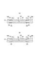
そこで、例えば特許文献1に示されているような再被覆方法が提案されている。この再被覆方法では、図6(a)および(b)に示すように、接続される光ファイバ100a、100bの先端の被覆101aを一部除去して被覆101の外径を細径化し、細径部102を形成している。そしてこの細径部102の先端の被覆101を除去して光ファイバ100a、100bを融着接続し、この後、融着接続部103およびその近傍104を光ファイバ100a、100bの被覆101とほぼ等しい径となるようにモールド樹脂105によりモールドしている。
【0006】
【特許文献1】
特開平5−264848号公報
【0007】
【発明が解決しようとする課題】
しかしながら、上述した図6(a)および(b)に示す再被覆方法によると、モールド樹脂105部分の外径を光ファイバ100a、100bの被覆101の外径と合わせることができるものの、以下のような問題が残る。
【0008】
まず、第1に、モールド樹脂105と光ファイバ100a、100bの被覆101との重なり部分すなわちオーバーラップ部分106ではモールドされる樹脂の厚さが依然として薄いという構造上の問題がある。
【0009】
これに加えて、モールド被覆に使用するモールド樹脂105の硬化収縮率が大きいこと、およびモールド樹脂105そのものの引張破断強度が低く且つ引張破断伸びが小さいため、注入されたモールド樹脂105が硬化する際の収縮によって生じるモールド樹脂105と被覆101との界面107におけるクラックを十分に防止することができない。特に、スクリーニング(張力付加)巻き替えを行った際にクラックが生じやすいという問題が残る。
【0010】
また、オーバーラップ部分106では、モールド樹脂105の厚さが薄いという問題に加えて、モールド樹脂105と光ファイバ100a、100bの最外層を構成する被覆101との密着力が低いため、モールド樹脂105を硬化させた後にバリ等の余分な樹脂を除去するために、エタノールなどを用いた拭き取り処理(エタノール拭き)を行う際、オーバーラップ部分106が剥がれてしまうおそれがある。
【0011】
さらに、接続される光ファイバ100a、100bの先端の被覆101aを細径化する際にサンドペーパーを用いているが、被覆101の厚さはわずかに60μm程度であるため、細径化には極めて高度のスキルと時間を要し作業効率が悪い。また、時にはガラスにダメージを与えて、ファイバ強度を低下させてしまうおそれもある。
【0012】
本発明は、前述した問題点に鑑みてなされたものであり、モールド/被覆界面におけるクラックの発生およびオーバーラップ部分の剥がれを発生させることなく光ファイバの被覆外径に近い外径で再被覆を行うことのできる光ファイバ融着接続部の再被覆方法を提供することを目的とする。
【0013】
また、光ファイバ融着接続部の近傍も光ファイバの被覆外径に近く、モールド/被覆界面におけるクラックの発生およびオーバーラップ部分の剥がれがなく信頼性の高い再被覆部を備えた光ファイバを提供することを目的とする。
【0014】
【課題を解決するための手段】
上記目的を達成するため、本発明に係る光ファイバ融着接続部の再被覆方法は、光ファイバ融着接続部の裸ファイバ部上に、硬化収縮率が6.0%未満であって、引張破断伸びが70%以上であって、引張破断強度が20MPa以上であって、光ファイバの最外層被覆を構成する樹脂との密着力が200N/m以上となる特性を有する樹脂組成物を用いてモールド被覆を形成する被覆工程を含むことを特徴とする。ここで裸ファイバはガラスファイバ又はカーボンコートされたガラスファイバを含む。
【0015】
かかる構成によれば、モールド樹脂自体の硬化収縮率が低いので、モールド樹脂が硬化する際の収縮が少なく、モールド/被覆界面に発生するクラックおよびオーバーラップ部分の剥がれを防止することができる。これにより、従来のように光ファイバ先端の被覆を細径化する必要がなくなるため、強度低下を招くことなく、作業効率の向上を図ることができる。
【0017】
かかる構成によれば、モールド樹脂の引張破断伸びが大きく、且つ引張破断強度も高いため、モールド樹脂が硬化する際の収縮力に抵抗することができ、モールド/被覆界面にクラックが発生するのを防止することができる。これにより、従来のように光ファイバ先端の被覆を細径化する必要がなくなるため、強度低下を招くことなく、作業効率の向上を図ることができる。
【0018】
なお、モールド/被覆界面にクラックが発生するのを防止するためには、この樹脂組成物は、引張破断伸びが82%以上、且つ引張破断強度が23MPa以上であることがより好ましい。
【0020】
かかる構成によれば、モールド樹脂と光ファイバの最外層被覆との密着力が強いため、モールド樹脂が硬化する際の収縮に抵抗してオーバーラップ部分の剥がれを防止することができる。これにより、従来のように光ファイバ先端部の被覆を細径化する必要がなくなるため、強度低下を招くことなく、作業効率の向上を図ることができる。
【0021】
一方、密着力が200N/mに満たない場合、オーバラップ部分が剥がれてしまい強度低下を生じてしまうという問題がある。
【0022】
なお、オーバーラップ部分の剥がれを防止するためには、密着力が400N/m以上であることがより好ましい。また450N/m以上であるとさらに望ましい。
【0023】
なお、モールド/被覆界面に発生するクラックおよびオーバーラップ部分の剥がれを防止するためには、モールド樹脂の硬化収縮率が5.5%以下であることがより好ましい。
【0024】
ここで、モールド被覆は裸ファイバ部を完全に覆うように形成すればよいが、望ましくは、裸ファイバ部上から各光ファイバ先端の被覆上に重なるように形成する。モールド樹脂自体が、硬化する際の収縮力に抵抗することができ、オーバラップ部分の剥がれを防止することができるため、光ファイバ先端部の被覆にダメージを与えることもなく、しかも一部で光ファイバの被覆とモールド樹脂とのオーバラップ部分を形成することにより、確実な保護が可能となる。
【0025】
また、裸ファイバ部のみを覆い光ファイバの被覆とは光ファイバの光軸に対して垂直な面でのみ接するように形成しても、モールド樹脂の引張破断伸びが大きく、且つ引張破断強度も高く、モールド樹脂が硬化する際の収縮力も小さいため、クラックの発生も剥がれもない、確実な再被覆を実現することができる。
【0026】
また、光ファイバの融着接続部に上述した再被覆すなわちモールド樹脂を形成した光ファイバは、モールド/被覆界面のクラックの発生もなく、オーバーラップ部分の剥がれもない。
【0027】
【発明の実施の形態】
以下本発明の実施の形態について図面を参照しつつ詳細に説明する。
【0028】
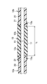
本発明では、図1に示すように、光ファイバ10a、10bの融着接続部11における裸ファイバ部12a、12b上に、硬化した状態での引張破断伸びが70%以上、かつ引張破断強度が20MPa以上となる特性を有する樹脂組成物を用いてモールド被覆13を形成するようにしたことを特徴としている。
【0029】
例えば、図2乃至図4にこの再被覆工程を示すように、光ファイバ融着接続部11の裸ファイバ部12a、12bにモールド金型1(EP1197311A1公報参照)を装着する。このモールド金型は上下1対のモールド金型14A、14Bで構成されている。そして、ここでは、この上下モールド金型14A、14Bの樹脂注入ゲート15からキャビティ領域16に前述した特性を有する樹脂組成物としてウレタンアクリレート系の紫外線硬化型樹脂(モールド樹脂17)を供給した後、キャビティ領域16に硬化エネルギーである紫外線18を照射してモールド樹脂17を硬化させる。その後、上下モールド金型14A、14Bをはずしてばり19がある場合にはこのばり19をアルコール(例えばエタノール)で拭き取るという方法がとられる。
【0030】
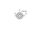
すなわち、まず、図2(a)および(b)に示すように、例えば紫外線18を透過する石英ガラスからなる上モールド金型14Aと下モールド金型14Bとの間に形成されるキャビティ領域16の中心に融着接合のなされた裸ファイバ部12がくるように配置し、ウレタンアクリレート系の紫外線硬化型樹脂であるモールド樹脂17を円柱状のキャビティ領域16内に充填する。
【0031】
この状態でキャビティ領域16に紫外線18を照射してモールド樹脂17を硬化させる。このとき上モールド金型14Aと下モールド金型14Bとの間にはばり19が形成されていることが多い。
【0032】
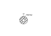
そして、図3に径方向断面図を示すように、上モールド金型14Aおよび下モールド金型14Bをはずして、アルコールを染み込ませた不織布を用いてばり19を拭き取る。
【0033】
このようにして、図4に径方向断面図を示すように、ばりのない再被覆を得る。この再被覆長さLは例えば有着接続前に被覆除去するための被覆除去工具により異なるが、8から38mm程度であった(図1参照)
【0034】
次に、種々の特性を有するモールド樹脂を用意しこれらのモールド樹脂17を用いて再被覆を行い、モールド被覆13の強度や収縮率等を測定した。
【0035】
まず、光ファイバ10a、10bとして、外径125μmのシングルモードの光ファイバ10の裸ファイバ部12に、ウレタンアクリレート系の紫外線硬化型樹脂による2層の被覆20を施した外径245μmの光ファイバ10a、10bを用いる。
【0036】
この光ファイバ10a、10bの端部の被覆20をリムーバーあるいは熱硫酸等により除去し、裸ファイバ部12端面をファイバカッターでカットして、アセトンによりガラス表面の超音波洗浄を行う。なお、ここでは、アセトンに代えて、H2SO4を用いてもよい。
このような光ファイバ10a、10bを2組準備し、端面同士をつき合わせて融着接続を行った。
【0037】
この融着接続部11を含む光ファイバ10a、10bを、前述した上下モールド金型14A、14Bにセットして、ウレタンアクリレート系オリゴマーをベースとし、希釈モノマー、光開始剤を添加した紫外線硬化型樹脂からなる6種類のモールド樹脂17をキャビティ領域16に注入し、紫外線18を照射してモールド樹脂17を硬化させた。
【0038】
そして、モールド金型14A、14Bから光ファイバ10a、10bを取り出して、ばり19等の不要部分(未硬化部分を含む)をエタノールにより拭き取り、顕微鏡下にてモールド被覆13の観察を行うと共に、モールド被覆13と光ファイバ10の被覆20との界面21におけるクラックの発生状況、および被覆20とモールド被覆13のオーバーラップ部分13aの剥離発生状況を調べた。
【0039】
さらに、一定張力付加によるスクリーニング巻き替えを施し、再度顕微鏡下においてモールド被覆13の観察を行った。
【0040】
以上の観察の結果は、表1に示すとおりであった。なお、モールド樹脂17として、オリゴマーのウレタン基濃度、分子量および配合量、ならびにモノマーの種類および配合量を調整することにより特性を変化させたA〜Fの6種類の樹脂を採用した。
【0041】
【表1】

なお、引張破断伸び、引張破断強度の測定は、各モールド樹脂17と同じ組成を有する試験片について、JISK7127に準拠して引張破断伸びと引張破断強度を測定した。このときの標線間距離は25mm、温度23℃、湿度50%RHの環境下で、引張速度50mm/分で測定した。
【0043】
このときの試験片は、以下のようにして得られたものである。まず、各モールド樹脂17と同じ組成を有する液状組成物を、アプリケータを用いてガラス上に塗布する。そして、メタルハライドランプを用いて空気雰囲気下で1.0J/cm2の紫外線を照射して、厚さ約200μmの硬化膜を作製する。このようにして形成された硬化膜から2号試験片を採取して得られたものである。
【0044】
また、光ファイバ最外層の被覆20との密着力(貼り付き力)の測定は、以下のようにして行った。
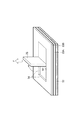
図5に示すように、まず、光ファイバ最外層被覆樹脂の液状組成物をアプリケータを用いてガラス板22上に塗布し、メタルハライドランプを用いて窒素雰囲気下で0.5J/cm2の紫外線を照射して、厚さ約130μmの硬化膜23Aを作製する。
【0045】
また、モールド樹脂17用の液状組成物をアプリケータを用いて前述の硬化膜23A上に塗布し、メタルハライドランプを用いて空気雰囲気下で0.1J/cm2の紫外線を照射して、厚さ約130μmの硬化膜23Bを作製する。
【0046】
この硬化膜23Bに幅1cmで一定長さの短冊状の切れ目24を入れた後、これの一端を剥がして一定長さを90度に折り曲げて折曲げ部25を作製する。そして、この折曲げ部25の先端を引っ張って全体を剥離させ、剥離時の引張り力Fを幅で割って密着力とした。測定は、温度23℃、湿度50%RHの環境下において行われた。
【0047】
また、硬化収縮率は、硬化前の液状樹脂の比重をdi、硬化後の樹脂の比重をdsとすると、硬化収縮率={(ds−di)/ds}×100(%)で得られる。
【0048】
ここで、エタノールで拭いた後のモールド/被覆界面21のクラック発生率あるいはオーバーラップ部分13aの剥がれの発生率を、15のサンプルに対して算出した。さらに、スクリーニング巻き替え後のモールド/被覆界面21のクラック発生率あるいはオーバーラップ部分13aの剥がれの発生率は、エタノールで拭いた後にモールド/被覆界面21のクラック発生もオーバーラップ部分13aの剥がれの発生もなかったサンプルに対して算出した。
【0049】
表1に示したように、モールド樹脂A、Bを用いた場合には、硬化収縮率の低減によりモールド樹脂硬化後モールド/被覆界面のクラックは発生しなくなり、且つ引張破断強度と引張破断伸びが高いため、スクリーニング巻き替え後にクラックが発生することもなくなった。また、最外層被覆20に対する密着力が高いためオーバーラップ部分13aの剥がれもなくなり、適正な再被覆が行われたことがわかる。
【0050】
次に、モールド樹脂Cを用いたところ、硬化収縮率は、5.7%、引張破断強度は、82%、引張破断伸びは24Mpa、最外層被覆20に対する密着力は280N/mであった。このとき、モールド樹脂硬化後、エタノール拭きを行ったところ、モールド/被覆界面21にクラックが発生し、発生率は3/15であった。さらに、スクリーニング巻き替え後にもモールド/被覆界面21にクラックが発生し、発生率は2/10であった。さらにまた、このときエタノール拭き後のオーバラップ部分13aの剥がれが生じ、エタノール拭き後の剥がれ発生率は2/15、スクリーニング巻き替え後の剥がれ発生率は2/10であった。
【0051】
次に、モールド樹脂Dを用いたところ、硬化収縮率は、5.6%、引張破断強度は、94%、引張破断伸びは19Mpa、最外層被覆20に対する密着力は280N/mであった。このときエタノール拭き後のモールド樹脂硬化後モールド/被覆界面21にクラックが発生した。発生率は3/15であった。さらに引張破断強度が低いため、スクリーニング巻き替え後に全サンプルに対し、モールド/被覆界面21にクラックが発生し、不適正な再被覆ということができる。さらにこのときエタノール拭き後のオーバラップ部分13aに剥がれが生じ、その発生率は2/15であった。
【0052】
次に、モールド樹脂Eを用いたところ、硬化収縮率は、5.2%、引張破断強度は、23Mpa、引張破断伸びは67%、最外層被覆20に対する密着力は250N/mであった。硬化収縮率の低減によりモールド樹脂硬化後モールド/被覆界面21のクラックは発生しなくなったが、引張破断伸びが小さいためスクリーニング巻き替え後に全サンプルに対しモールド/被覆界面21にクラックが発生し、不適正な再被覆であるということができる。さらに、このときエタノール拭き後にオーバラップ部分13aの剥がれが生じ、エタノール拭き後の剥がれ発生率は3/15、スクリーニング巻き替え後の剥がれ発生率は3/12であった。
【0053】
次に、モールド樹脂Fを用いたところ、硬化収縮率が6.1%と大きいため、全サンプルに対しモールド樹脂硬化後(エタノール拭き後)モールド/被覆界面21のクラックが発生し、且つ最外層被覆20に対する密着力が150N/mと低いため全サンプルに対し、オーバーラップ部分13aの剥がれが発生した。これは、不適正な再被覆であるということができる。
【0054】
上述したように、モールド樹脂D〜Fを使用した場合のように、モールド/被覆界面21におけるクラックの発生あるいはオーバーラップ部分13aの剥がれが発生したものは、該当部分を削り取り、再度モールド樹脂17を塗って硬化させる修正作業が必要となり、作業効率は大幅に低下するため、不適正な再被覆であるということができる。
【0055】
以上の測定結果から、硬化収縮率が6.1%では全件でエタノールで吹いた後に界面でクラックが発生した。硬化収縮率が6.1%では、大きすぎて不適であることがわかる。硬化収縮率が5.7%以下では、エタノールで拭いた後に界面でのクラック発生率が顕著に少なくなる。引張破断伸びは67%では小さすぎ、引張破断強度は19MPaでは低すぎることがわかる。また、密着力は150N/mでは低すぎることがわかる。
【0056】
これらの結果から、引張破断伸びが70%以上、引張破断強度が20MPa以上、密着力は200N/m以上の特性を有するモールド樹脂17であれば、適正な再被覆を行うことができることがわかる。
また、実施例3、4および5の検査結果によれば、引張破断伸びが82%および引張強度が23MPa以上であったものはスクリーニング通過の界面のクラック発生率やオーバーラップ部分の剥がれ発生率が顕著に少ない。
【0057】
以上説明したように、モールド被覆17が引張破断伸び90%以上引張強度25Mpa、密着力は400N/m以上の特性を有するモールド樹脂17であれば、極めて適正な再被覆を行うことができることがわかる。
【0058】
本発明に係る光ファイバ融着接続部の再被覆方法では、モールド/被覆界面21におけるクラックの発生およびオーバーラップ部分13aの剥がれを発生することなく光ファイバ10の被覆20外径に近い外径で再被覆を行うことができる。
【0059】
なお、本発明に係る光ファイバ融着接続部の再被覆方法は、前述した実施形態に限定されるものではなく、適宜な変形、改良等が可能である。
【0060】
すなわち、前述した実施形態では、紫外線硬化型樹脂としてウレタンアクリレート樹脂を用いたが他の紫外線硬化樹脂を用いてもよいことはいうまでもない。
【0061】
また、紫外線硬化型樹脂に限定されることなく、熱エネルギーで硬化する熱硬化性樹脂などにも適用可能である。
【0062】
【発明の効果】
以上説明したように、本発明に係る光ファイバ融着接続部の再被覆方法によれば、モールド/被覆界面におけるクラックの発生およびオーバーラップ部分の剥がれを発生することなく光ファイバの被覆外径に近い外径で再被覆を行うことができる。
【0063】
また、本発明の光ファイバによれば、再被覆部においてもモールド/被覆界面におけるクラックの発生およびオーバーラップ部分の剥がれを発生もなく、信頼性の高い長距離用光ファイバを実現することが可能となる。
【図面の簡単な説明】
【図1】本発明に係る光ファイバ融着接続部の再被覆方法により行った再被覆部分の断面図である。
【図2】(a)、(b)は、この発明にかかる光ファイバ融着接続部の再被覆方法の一工程を示す断面図である。
【図3】ばりを取る前の再被覆部分の断面図である。
【図4】ばりを取った後の再被覆部分の断面図である。
【図5】密着力測定方法を示す斜視図である。
【図6】 (a)、(b)は、従来の光ファイバ融着接続部の再被覆方法による再被覆部分の断面図である。
【符号の説明】
10 光ファイバ
11 融着接続部
12 裸ファイバ部
13 モールド被覆
14A、14B モールド金型
16 キャビティ領域
17 モールド樹脂(樹脂組成物)
18 紫外線(硬化エネルギー)
20 被覆[0001]
BACKGROUND OF THE INVENTION
The present invention relates to an optical fiber fusion splicing method and an optical fiber, and more particularly to re-covering a portion exposed by fusion splicing of an optical fiber.
[0002]
[Prior art]
In a long-distance optical transmission line in which a closure or a terminal box cannot be installed, for example, a submarine cable, it is necessary to form an optical fiber cable of several tens km in some cases. When manufacturing such a long optical fiber cable, a low-loss and high-strength connection is made for an optical fiber that is less than the cable length, and the shape and outer diameter of this connection part are formed to the same extent as the optical fiber coating part. There is a need.
[0003]
Conventionally, after the optical fiber with the coating removed is fusion spliced at the end face, to recoat the exposed optical fiber, the recoated portion is coated with an ultraviolet curable resin, and the recoated portion is cured by irradiating ultraviolet rays. And forming a mold coating (re-coating) has been adopted.
[0004]
However, in such a method for re-coating an optical fiber fusion spliced portion, in order to perform mold coating so that the outer diameter of the optical fiber coating is approximately equal to the outer diameter, the overlap between the coating and the resin (overlap) is required. ) Portion, the molded resin thickness is reduced. For this reason, cracks may occur in the mold / coating interface, which is the interface between the mold coating and the optical fiber coating, due to shrinkage when the injected resin is cured.
[0005]
Therefore, for example, a re-coating method as shown in
[0006]
[Patent Document 1]
JP-A-5-264848 [0007]
[Problems to be solved by the invention]
However, according to the re-coating method shown in FIGS. 6A and 6B described above, the outer diameter of the
[0008]
First, there is a structural problem that the thickness of the resin to be molded is still thin at the overlapping portion of the
[0009]
In addition to this, the
[0010]
In addition, in the
[0011]
Furthermore, sandpaper is used to reduce the diameter of the
[0012]
The present invention has been made in view of the above-mentioned problems, and re-coating is performed with an outer diameter close to the outer diameter of the optical fiber without generating cracks at the mold / coating interface and peeling off of the overlap portion. It is an object of the present invention to provide a method for re-coating an optical fiber fusion spliced portion that can be performed.
[0013]
In addition, the optical fiber with a highly reliable re-coating part is provided in the vicinity of the optical fiber fusion splicing part, which is close to the outer diameter of the optical fiber coating, and there is no occurrence of cracks at the mold / coating interface and peeling of the overlap part. The purpose is to do.
[0014]
[Means for Solving the Problems]
In order to achieve the above object, the method for recoating an optical fiber fusion spliced portion according to the present invention has a cure shrinkage ratio of less than 6.0% on the bare fiber portion of the optical fiber fusion spliced portion , Using a resin composition having a characteristic that the elongation at break is 70% or more, the tensile strength at break is 20 MPa or more, and the adhesive strength with the resin constituting the outermost layer coating of the optical fiber is 200 N / m or more. A coating process for forming a mold coating is included . Here, the bare fiber includes glass fiber or carbon-coated glass fiber.
[0015]
According to such a configuration, since the curing shrinkage rate of the mold resin itself is low, there is little shrinkage when the mold resin is cured, and cracks occurring at the mold / coating interface and peeling of the overlap portion can be prevented. Thereby, since it is not necessary to reduce the diameter of the coating at the tip of the optical fiber as in the prior art, it is possible to improve work efficiency without causing a decrease in strength.
[0017]
According to this configuration, since the tensile elongation at break of the mold resin is large and the tensile strength at break is high, it is possible to resist the shrinkage force when the mold resin is cured, and cracks are generated at the mold / coating interface. Can be prevented. Thereby, since it is not necessary to reduce the diameter of the coating at the tip of the optical fiber as in the prior art, it is possible to improve work efficiency without causing a decrease in strength.
[0018]
In order to prevent the occurrence of cracks at the mold / coating interface, the resin composition preferably has a tensile elongation at break of 82% or more and a tensile strength at break of 23 MPa or more.
[0020]
According to such a configuration, since the adhesive force between the mold resin and the outermost layer coating of the optical fiber is strong, it is possible to resist the shrinkage when the mold resin is cured and to prevent the overlap portion from peeling off. As a result, it is not necessary to reduce the diameter of the coating at the tip of the optical fiber as in the prior art, so that the working efficiency can be improved without causing a decrease in strength.
[0021]
On the other hand, when the adhesive force is less than 200 N / m, there is a problem that the overlap portion is peeled off and the strength is lowered.
[0022]
In addition, in order to prevent peeling of an overlap part, it is more preferable that adhesive force is 400 N / m or more. Further, it is more desirable to be 450 N / m or more.
[0023]
In order to prevent cracks occurring at the mold / coating interface and peeling of the overlap portion, it is more preferable that the curing shrinkage of the mold resin is 5.5% or less.
[0024]
Here, the mold coating may be formed so as to completely cover the bare fiber portion. Preferably, the mold coating is formed so as to overlap the coating on the tip of each optical fiber from the bare fiber portion. The mold resin itself can resist the shrinkage force when it is cured, and can prevent the overlap part from peeling off. By forming an overlap portion between the fiber coating and the mold resin, reliable protection can be achieved.
[0025]
Further, even if the bare fiber portion is covered and the optical fiber coating is formed so as to be in contact with only the surface perpendicular to the optical axis of the optical fiber, the tensile elongation at break of the mold resin is large and the tensile breaking strength is also high. Further, since the shrinkage force when the mold resin is cured is small, it is possible to realize reliable recoating without generation of cracks or peeling.
[0026]
In addition, in the optical fiber in which the above-mentioned re-coating, that is, the mold resin is formed on the fusion spliced portion of the optical fiber, cracks at the mold / coating interface do not occur, and the overlap portion does not peel off.
[0027]
DETAILED DESCRIPTION OF THE INVENTION
Hereinafter, embodiments of the present invention will be described in detail with reference to the drawings.
[0028]
In the present invention, as shown in FIG. 1, on the
[0029]
For example, as shown in FIGS. 2 to 4, the mold 1 (see EP 1197311A1) is attached to the
[0030]
That is, first, as shown in FIGS. 2A and 2B, the
[0031]
In this state, the
[0032]
Then, as shown in the radial cross-sectional view of FIG. 3, the upper mold 14 </ b> A and the lower mold 14 </ b> B are removed, and the
[0033]
In this way, a re-coating without flash is obtained, as shown in the radial cross section in FIG. The re-coating length L is, for example, about 8 to 38 mm, although it varies depending on the coating removal tool for removing the coating before the attachment connection (see FIG. 1).
[0034]
Next, mold resins having various characteristics were prepared, and re-coating was performed using these mold resins 17, and the strength and shrinkage rate of the
[0035]
First, as the
[0036]
The
Two sets of such
[0037]
The
[0038]
Then, the
[0039]
Furthermore, screening rewinding by applying a constant tension was performed, and the
[0040]
The results of the above observations are as shown in Table 1. As the
[0041]
[Table 1]
In addition, the measurement of the tensile breaking elongation and the tensile breaking strength measured the tensile breaking elongation and the tensile breaking strength based on JISK7127 about the test piece which has the same composition as each
[0043]
The test piece at this time was obtained as follows. First, the liquid composition which has the same composition as each
[0044]
Moreover, the measurement of the adhesive force (adhesion force) with the coating | cover 20 of optical fiber outermost layer was performed as follows.
As shown in FIG. 5, first, a liquid composition of an optical fiber outermost layer coating resin is applied onto a
[0045]
In addition, the liquid composition for the
[0046]
After forming a strip-shaped
[0047]
Further, the curing shrinkage ratio is obtained by the following formula: curing shrinkage ratio = {(ds−di) / ds} × 100 (%) where the specific gravity of the liquid resin before curing is di and the specific gravity of the resin after curing is ds.
[0048]
Here, the crack occurrence rate of the mold /
[0049]
As shown in Table 1, when mold resins A and B are used, cracks at the mold / coating interface do not occur after the mold resin is cured due to a reduction in cure shrinkage, and tensile strength at break and tensile elongation at break are high. Due to the high cost, cracks were not generated after screening rewinding. Moreover, since the adhesive force with respect to the outermost layer coating | cover 20 is high, peeling of the
[0050]
Next, when the mold resin C was used, the cure shrinkage rate was 5.7%, the tensile strength at break was 82%, the tensile elongation at break was 24 Mpa, and the adhesion to the
[0051]
Next, when the mold resin D was used, the cure shrinkage ratio was 5.6%, the tensile strength at break was 94%, the tensile elongation at break was 19 Mpa, and the adhesion to the
[0052]
Next, when the mold resin E was used, the cure shrinkage rate was 5.2%, the tensile breaking strength was 23 Mpa, the tensile breaking elongation was 67%, and the adhesion to the
[0053]
Next, when the mold resin F was used, the cure shrinkage ratio was as large as 6.1%. Therefore, cracks in the mold /
[0054]
As described above, as in the case where the mold resins D to F are used, if the occurrence of cracks at the mold /
[0055]
From the above measurement results, when the cure shrinkage was 6.1%, cracks occurred at the interface after blowing with ethanol in all cases. It can be seen that a cure shrinkage of 6.1% is too large to be suitable. When the cure shrinkage is 5.7% or less, the crack generation rate at the interface is remarkably reduced after wiping with ethanol. It can be seen that the tensile elongation at break is too small at 67% and the tensile strength at break is too low at 19 MPa. It can also be seen that the adhesion is too low at 150 N / m.
[0056]
From these results, it can be seen that an appropriate re-coating can be performed if the
In addition, according to the inspection results of Examples 3, 4 and 5, those having a tensile elongation at break of 82% and a tensile strength of 23 MPa or more have a crack generation rate at the screening passing interface and a peeling occurrence rate of the overlap portion. Remarkably few.
[0057]
As described above, it can be seen that if the
[0058]
In the method of re-coating the optical fiber fusion splicing portion according to the present invention, the outer diameter of the
[0059]
In addition, the re-coating method of the optical fiber fusion splicing part according to the present invention is not limited to the above-described embodiment, and appropriate modifications and improvements can be made.
[0060]
That is, in the above-described embodiment, the urethane acrylate resin is used as the ultraviolet curable resin, but it goes without saying that another ultraviolet curable resin may be used.
[0061]
Further, the present invention is not limited to the ultraviolet curable resin and can be applied to a thermosetting resin that is cured by thermal energy.
[0062]
【The invention's effect】
As described above, according to the optical fiber fusion splicing method according to the present invention, the outer diameter of the optical fiber can be increased without generating cracks at the mold / coating interface and peeling off of the overlap portion. Re-coating can be performed with a near outer diameter.
[0063]
Further, according to the optical fiber of the present invention, it is possible to realize a highly reliable long-distance optical fiber without occurrence of cracks at the mold / coating interface and peeling of the overlap portion even in the re-coated portion. It becomes.
[Brief description of the drawings]
FIG. 1 is a cross-sectional view of a re-coating portion performed by a method of re-coating an optical fiber fusion spliced portion according to the present invention.
FIGS. 2A and 2B are cross-sectional views showing one step of a method for re-covering an optical fiber fusion spliced portion according to the present invention.
FIG. 3 is a cross-sectional view of a re-covered portion before deburring.
FIG. 4 is a cross-sectional view of a recoated portion after deburring.
FIG. 5 is a perspective view showing a method for measuring an adhesion force.
FIGS. 6A and 6B are cross-sectional views of a re-coating portion obtained by a conventional method of re-coating an optical fiber fusion spliced portion. FIGS.
[Explanation of symbols]
DESCRIPTION OF
18 UV (curing energy)
20 Coating
Claims (5)
Priority Applications (1)
| Application Number | Priority Date | Filing Date | Title |
|---|---|---|---|
| JP2003024003A JP4058626B2 (en) | 2002-01-31 | 2003-01-31 | Optical fiber fusion splicing method and optical fiber |
Applications Claiming Priority (3)
| Application Number | Priority Date | Filing Date | Title |
|---|---|---|---|
| JP2002024601 | 2002-01-31 | ||
| JP2002-24601 | 2002-01-31 | ||
| JP2003024003A JP4058626B2 (en) | 2002-01-31 | 2003-01-31 | Optical fiber fusion splicing method and optical fiber |
Publications (2)
| Publication Number | Publication Date |
|---|---|
| JP2003294974A JP2003294974A (en) | 2003-10-15 |
| JP4058626B2 true JP4058626B2 (en) | 2008-03-12 |
Family
ID=29253424
Family Applications (1)
| Application Number | Title | Priority Date | Filing Date |
|---|---|---|---|
| JP2003024003A Expired - Fee Related JP4058626B2 (en) | 2002-01-31 | 2003-01-31 | Optical fiber fusion splicing method and optical fiber |
Country Status (1)
| Country | Link |
|---|---|
| JP (1) | JP4058626B2 (en) |
Families Citing this family (1)
| Publication number | Priority date | Publication date | Assignee | Title |
|---|---|---|---|---|
| JP6943163B2 (en) * | 2017-12-08 | 2021-09-29 | 住友電気工業株式会社 | Optical fiber connection structure |
-
2003
- 2003-01-31 JP JP2003024003A patent/JP4058626B2/en not_active Expired - Fee Related
Also Published As
| Publication number | Publication date |
|---|---|
| JP2003294974A (en) | 2003-10-15 |
Similar Documents
| Publication | Publication Date | Title |
|---|---|---|
| JP4556372B2 (en) | Coated optical fiber | |
| EP0401324B1 (en) | High strength optical fiber splice | |
| US20220155540A1 (en) | Flexible Optical-Fiber Ribbon | |
| US6549712B2 (en) | Method of recoating an optical fiber | |
| JPWO2001035143A1 (en) | coated optical fiber | |
| JP3908015B2 (en) | Polarized fiber array | |
| TW201704789A (en) | Fiber and fiber ribbon | |
| JPH10170787A (en) | Manufacturing method of optical fiber ribbon | |
| JP4058626B2 (en) | Optical fiber fusion splicing method and optical fiber | |
| CN1678933A (en) | Resin-coated optical fiber, method of removing coating therefrom, and production process of optical fiber part | |
| US6908236B2 (en) | Method for molding optical fiber fusion spliced portion and optical fiber with molded fusion spliced portion | |
| JP6858216B2 (en) | Optical fiber and its manufacturing method | |
| JP4347233B2 (en) | Optical fiber | |
| JP4100966B2 (en) | Fusion splicing method of optical fiber | |
| JP2004037762A (en) | Recoating method for exposed cladding of optical fiber | |
| JPH11202174A (en) | Optical fiber ribbon | |
| JP2004004423A (en) | Glass optical fiber strand for fiber grating | |
| JP3303460B2 (en) | Glass fiber for optical transmission and method of manufacturing the same | |
| JP2003329860A (en) | Optical fiber strand | |
| JPH0766091B2 (en) | Optical fiber fusion splicing method | |
| JP2004331431A (en) | Method for forming recoated portion of optical fiber, mold member for molding, and optical fiber component | |
| JPH11202167A (en) | Optical fiber colored core and manufacturing method thereof | |
| JP3392991B2 (en) | Recoating method of fusion spliced part of optical fiber | |
| JP2943469B2 (en) | Processing method for fusion splicing terminal of optical fiber | |
| JP2001108874A (en) | Coated optical fiber |
Legal Events
| Date | Code | Title | Description |
|---|---|---|---|
| A621 | Written request for application examination |
Free format text: JAPANESE INTERMEDIATE CODE: A621 Effective date: 20050606 |
|
| A977 | Report on retrieval |
Free format text: JAPANESE INTERMEDIATE CODE: A971007 Effective date: 20070427 |
|
| A131 | Notification of reasons for refusal |
Free format text: JAPANESE INTERMEDIATE CODE: A131 Effective date: 20070509 |
|
| A521 | Written amendment |
Free format text: JAPANESE INTERMEDIATE CODE: A523 Effective date: 20070709 |
|
| TRDD | Decision of grant or rejection written | ||
| A01 | Written decision to grant a patent or to grant a registration (utility model) |
Free format text: JAPANESE INTERMEDIATE CODE: A01 Effective date: 20071121 |
|
| A61 | First payment of annual fees (during grant procedure) |
Free format text: JAPANESE INTERMEDIATE CODE: A61 Effective date: 20071204 |
|
| FPAY | Renewal fee payment (event date is renewal date of database) |
Free format text: PAYMENT UNTIL: 20101228 Year of fee payment: 3 |
|
| R150 | Certificate of patent or registration of utility model |
Free format text: JAPANESE INTERMEDIATE CODE: R150 |
|
| FPAY | Renewal fee payment (event date is renewal date of database) |
Free format text: PAYMENT UNTIL: 20101228 Year of fee payment: 3 |
|
| FPAY | Renewal fee payment (event date is renewal date of database) |
Free format text: PAYMENT UNTIL: 20111228 Year of fee payment: 4 |
|
| FPAY | Renewal fee payment (event date is renewal date of database) |
Free format text: PAYMENT UNTIL: 20111228 Year of fee payment: 4 |
|
| FPAY | Renewal fee payment (event date is renewal date of database) |
Free format text: PAYMENT UNTIL: 20121228 Year of fee payment: 5 |
|
| FPAY | Renewal fee payment (event date is renewal date of database) |
Free format text: PAYMENT UNTIL: 20121228 Year of fee payment: 5 |
|
| FPAY | Renewal fee payment (event date is renewal date of database) |
Free format text: PAYMENT UNTIL: 20131228 Year of fee payment: 6 |
|
| LAPS | Cancellation because of no payment of annual fees |