JP4057204B2 - Formwork fixing structure - Google Patents
Formwork fixing structure Download PDFInfo
- Publication number
- JP4057204B2 JP4057204B2 JP27861699A JP27861699A JP4057204B2 JP 4057204 B2 JP4057204 B2 JP 4057204B2 JP 27861699 A JP27861699 A JP 27861699A JP 27861699 A JP27861699 A JP 27861699A JP 4057204 B2 JP4057204 B2 JP 4057204B2
- Authority
- JP
- Japan
- Prior art keywords
- separator
- mold
- truss
- locking member
- plate
- Prior art date
- Legal status (The legal status is an assumption and is not a legal conclusion. Google has not performed a legal analysis and makes no representation as to the accuracy of the status listed.)
- Expired - Fee Related
Links
Images


Description
【0001】
【発明の属する技術分野】
本発明は、鉄骨鉄筋コンクリート構造(SRC構造)におけるトラス埋込PC板に対する柱又は梁用の型枠固定構造に関するものである。
【0002】
【従来の技術】
予め工場等で複数列状に設けたトラス筋をその一部を露出させてPC板に埋設したトラス埋込PC板が建物の壁材として用いられている。このようなトラス埋込PC板(以下単にPC板と言う)を用いてコンクリート壁を形成する場合、現場でこのPC板を外側の型枠として用い、その内面側(トラス露出面側)に対向して合板等からなる内側の型枠を固定保持してコンクリートを打設する。これにより、PC板が現場打ちコンクリートと一体化されて外壁が形成される。
【0003】
このようなPC板の内面側に型枠を形成する場合、型枠をPC板から所定の壁厚の間隔を隔てた位置に対向して固定保持するためにセパレータが用いられる。型枠形成に際し、PC板を下層階のスラブ等に支持してサポートにより垂直に保持し、壁材の鉄筋等が配筋された状態で、セパレータの端部を予め定められた位置のPC板内面側に固定する。その後、予めセパレータの位置に対応して孔が明いた型枠をPC板に対向させて配設し、セパレータを孔に挿通させてその突出部のボルトに締結具を装着して型枠を固定する。
【0004】
従来、このセパレータとPC板とを結合するために、予めPC板側にインサートナットを埋設し、このインサートナットに対しセパレータ端部のボルトを螺合させて固定していた。
【0005】
【発明が解決しようとする課題】
しかしながら、インサートナットに対しセパレータ端部のボルトを螺入させる従来の方法では、特に柱や梁等の部分で鉄筋が密集して配設されインサートナットまで手が届かない場合に、インサートナットから手が離れたまま離れた位置からセパレータをもってインサートナットに螺入させることは非常にむつかしく、作業性が悪かった、また、PC板の裏面で特に鉄筋等が密集している部分では周囲が薄暗くなりインサートナットの位置を目で確認することが困難となってセパレータ取付け作業の作業性をさらに低下させていた。
【0006】
一方、このようなインサートナットを用いずに、セパレータ端部に断面コ字状の保持具を螺着し、この保持具をPC板のトラス筋に対し引掛けてからセパレータを回してボルトを保持具内に突出させてトラス筋にセパレータを固定する方法が提案されている(実開昭60−57649号公報)。
【0007】
このような断面コ字状の保持具を有するセパレータを用いることにより、PC板のトラス筋に対しセパレータを結合しやすくなり、作業性が向上する。これにより、PC板を用いたRC構造(鉄筋コンクリート構造)における型枠形成の作業性の向上が図られる。
【0008】
しかしながら、このような断面コ字状の保持具を有するセパレータをSRC構造の建物に対し用いた場合には、PC板に対向して柱や梁の型枠を形成する場合に、従来、柱や梁の鉄骨を避けてセパレータを取付けていた。このため、例えば柱の型枠を形成する場合、柱中央の鉄骨の左右にセパレータを取付けてこれに型枠を固定保持するため、強度を確保するためには上下方向のセパレータの取付け間隔を非常に狭くしなければならず、取付け本数が多くなって作業が煩雑になるとともに左右方向のセパレータ配置の強度上のバランスが均一にならず型枠保持の信頼性を低下させていた。
【0009】
また、PC板のトラス筋の埋込方向や配列形態によっては、セパレータ取付け間隔を狭くしようとしたときにその位置にトラス筋が配設されていない場合があり、最適な位置にセパレータを取付けることができず強度上の問題を生じるおそれがあった。
【0010】
本発明は上記従来技術を考慮したものであって、SRC構造の建物にトラス筋を埋め込んだPC板を用いた場合に、強度上の問題を生じることなく型枠のセパレータをPC板に容易に確実に結合して型枠形成の作業性を向上させた型枠固定構造の提供を目的とする。
【0011】
【課題を解決するための手段】
前記目的を達成するため、本発明では、SRC構造におけるトラス埋込PC板に対向して柱又は梁用の型枠を固定する型枠固定構造であって、型枠を前記トラス埋込PC板から所定間隔の位置に固定保持する型枠固定具を用い、該型枠固定具は、前記トラス筋埋込PC板のトラス筋に係止する係止部材と、この係止部材に螺合して前記トラス筋に対しこの係止部材を固定するとともに前記型枠を前記トラス埋込PC板から所定間隔を隔てて保持するためのセパレータ部材と、このセパレータ部材を前記型枠に固定する締結部材とからなり、前記セパレータ部材は、柱又は梁を構成する鉄骨を貫通して前記トラス筋および型枠間に配設されたことを特徴とするトラス埋込PC板に対する柱又は梁用の型枠固定構造を提供する。
【0012】
この構成によれば、鉄骨に強度上支障のない程度の小径の孔を形成し、この孔を通してセパレータ先端の係止部材を挿通させてトラス筋に引掛けることができるため、強度バランス上の最適位置にセパレータ部材を配設して型枠固定具を取付けることができ、型枠の構造上の強度を確保することができる。また、セパレータ部材に螺合された係止部材は容易にトラス筋に引掛けて係止することができるため、係止後にセパレータ部材を回してトラス筋に対しセパレータ部材を固定させることができる。これにより、手の届きにくい狭い場所や目で位置が確認できない薄暗い場所であっても容易に確実に型枠固定具をPC板に結合することができ、SRC構造における型枠形成の作業性が向上する。
【0013】
また、前記型枠固定具の係止部材は、前記セパレータ部材端部のネジ部が螺入するナットを有するとともに、このセパレータ部材に対する係止部材の回転を防止するための回り止めナットを有することを特徴としている。
【0014】
この構成によれば、係止部材をトラス筋に係止する前の状態で係止部材がセパレータ部材に対する回転が防止されるため、例えば縦方向のトラス筋に対し係止部材を横から引掛けて係止させる場合に、係止部材がその自重により回転することを防止することができ係止操作が円滑に行われる。
【0015】
【発明の実施の形態】
以下図面を参照して本発明の実施の形態について説明する。
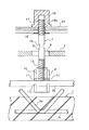
図1は本発明の実施の形態に係る型枠固定構造の一部断面構成説明図であり、図2はそのA−A方向から見た一部断面構成説明図である。また、図3は、その型枠固定具を構成する係止部材の単品図である。
【0016】
PC板(トラス埋込PC板)1は、埋設されたトラス2の露出面を建物内側に向けて配設される。トラス2は、図1の図面に垂直方向に沿って対向して配置した一対の波状あるいはジグザグ状の鉄筋2a,2aと、これらの鉄筋2a,2aの露出した頂部に接合される鉄筋2bと、鉄筋2a,2aの埋設部に接合される鉄筋2cとにより構成される。
【0017】
このPC板1の内面側に柱又は梁を構成する鉄骨5およびこの鉄骨5の周辺に主筋3およびフープ筋4が設けられる。なお、柱等の場合には、例えば断面で十字状にクロスする鉄骨を配設し、その周囲に主筋3が設けられ、この主筋3を囲んでフープ筋4が巻回される構成等となる場合もあるが、図では簡略化してある。また、PC板1の厚さや鉄筋2a,2b,2cの太さ等についても、図では構成の明瞭化のために、PC板1を大きく描き、トラス筋の鉄筋の径は柱を構成する主筋3と同等の径としてあるが、実際の例ではトラス筋の径は主筋3の径より小さい場合が多い。
【0018】
鉄骨5にはこの鉄骨5の設計上の強度に影響を与えない程度の小径の孔(図では誇張して大きく描いてある)6が形成される。この鉄骨5の孔6を挿通して型枠固定具7が取付けられる。この型枠固定具7は、トラス2の鉄筋2bに係合する係止部材8と、この係止部材8に螺合する間隔保持用のセパレータ9と、このセパレータ9の内側の端部に装着された締結具10とにより構成される。
【0019】
係止部材8は、図3に示すように、鉄骨5の孔6を通過できる大きさに曲げられたU字状の鉄板または鋳物等からなり、U字の両片には鉄筋を嵌入させて係止するための切欠き孔11が形成される。この切欠き孔11の開口部にはフック状の突起11aが形成される。この係止部材8には、ナット部材12が溶接により固着される。このナット部材12に対し、セパレータ9の先端部に形成したネジ14が螺合する。なお、U字状の係止部材8を鋳物で製造した場合は、ナット部材を含めて一体化させてもよい。
【0020】
ナット部材12の上面には回り止めナット13が設けられる。前記セパレータ9のネジ14はこの回り止めナット13の雌ねじに螺合する。このような回り止めナット13を介してセパレータ9をナット部材12に螺合させることにより、縦方向(上下方向)の鉄筋2bに係止部材8の切欠き孔11を嵌め込むために切欠き孔11の開口を横にした状態で係止部材8をセパレータ9に保持した場合に、係止部材8がその自重で回転することが防止され、係止部材8を鉄筋2bに取付ける作業が円滑に行われる。
【0021】
セパレータ9の途中にはスパナ掛け用の凹部15が形成される。セパレータ9の内側の端部のネジ17に固定板16が螺合する。セパレータ9の端部は、合板からなる型枠18に形成された孔18aを通して型枠の内側(建物内部側)に突出する。この型枠18の内側に突出したセパレータ9のネジ17に締結具10が螺着され、固定板16と締結具10間に型枠18が挟まれ、締結具10によって締め付けられて固定される。
【0022】
型枠18の後面(建物内部側)には、型枠支持用の端太材(図示しない)が締結具10に固定されて設けられる。この端太材は、角材あるいは丸パイプ等からなり、柱用の型枠の場合には、縦端太材が型枠18の後面に接して取付けられ、その後面側に横端太材が通常2本組で上下に適当な間隔で設けられる。この場合、締結具10をT字状として、2本の横端太材に係止させ、このT字状締結具とセパレータ9とを緊結することにより、端太材を介してセパレータ9の固定板16と締結具間に型枠18を挟持して固定保持する構成としてもよい。
【0023】
型枠18を組立る場合、まず建築途上の床コンクリートの上面に、PC板1をトラス露出面を内側に向けて載置し、サポートにより垂直に保持して固定する。この状態で、鉄骨5の孔6を通して型枠固定具7を挿入してその先端の係止部材8をPC板1のトラス2の鉄筋2bに引掛け、切欠き孔11に鉄筋2bを嵌め込む。このとき、前述のように回り止め13の作用により係止部材8は自重で回転することなくセパレータ9の先端に保持される。
【0024】
続いて、セパレータ9を回してその先端のネジ14をナット12から切欠き孔11内に突出させて鉄筋2bを切欠き孔11内に固定する。このセパレータ9の回転操作中、切欠き孔11の開口部のフック状の突起11a内に鉄筋2bが収まるため、係止部材8の回転が防止される。因みに、前記回り止めナット13は係止部材8が自重では回転しない程度に締付けられ、このセパレータ9の回転操作を阻害するものではない。
【0025】
次に、型枠18を柱の鉄骨5に沿って立て、孔18aから型枠18の後面(建物内部側)にセパレータ9の端部のネジ17を突出させる。次に、この型枠18の後面側に突出したセパレータ9のネジ17に締結具10を装着して型枠18を固定し、さらに端太材を固定する。これにより型枠18がPC板に対向した状態で組立られて固定保持される。この型枠内にコンクリートを打設する。コンクリート硬化後、締結具10を外し、型枠18を取外す。
【0026】
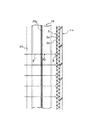
図4は、上記本発明の実施形態の斜視図である。
図示したように、セパレータ9の先端の係止部材8は切欠き孔11を横にした状態で鉄骨5の孔6を挿通してトラス2の鉄筋2bに引掛けられる。なお、トラス2はPC板1の内面に複数列形成されているが、図では1列のみ示す。
【0027】
図5は、本発明の別の実施の形態の構成説明図である。
この実施形態は、カプラー19で連結された2本のロッド9a,9bによりセパレータを構成したものである。このカプラー19によりセパレータの長さを調整し、型枠18の出入り調整を行うことができる。20は戻り止めであり、カプラー19で調整した長さの位置に両ロッド9a,9bを固定する。セパレータ端部のネジ17に連結具21が螺合し、この連結具21の端部にネジ部材(図示しない)が装着され、このネジ部材が型枠18の後面側に突出する。この突出したネジ部材に対し、連結具10aが取付けられ、その端部のネジ22に締結具(図示しない)が装着される。
【0028】
この図5の実施形態によれば、型枠18の組立前にロッド9a,9bからなるセパレータの長さが調整可能であるとともに、型枠組立後にその出入り調整が可能になる。型枠の組立手順は前述の実施形態と同様である。
【0029】
図6は本発明の別の実施の形態に係る型枠固定構造の壁および柱部分の水平断面図であり、図7および図8はそれぞれその型枠を取外した後の正面図および柱部分の断面図である。
この実施形態は、壁23と一体的に柱24および梁25のコンクリート打ちを行う場合の構成を示す。壁23に対応してPC板1aが配設され、柱24に対応してPC板1bが配設される。柱24は、鉄骨26およびその周囲の主筋27およびこれを巻回するフープ筋28により構成される。柱24の鉄骨26の上部両側には梁25を構成する鉄骨29が溶接により接合される。
【0030】
PC板1aに対向して壁23を形成する型枠30が配設される。PC板1bに対向して柱24を形成する型枠31が配設されその両側に柱側面の型枠32が配設される。柱24の型枠31,32の外側に丸パイプからなる縦端太材33および横端太材34が設けられる。
【0031】
柱用のPC板1bに対向する型枠31は、前述の実施形態と同様に、鉄骨26のウェブ26aに形成した孔35を挿通する型枠固定具36により固定保持される。この型枠固定具36は、前述の図1、図2の例と同様に、PC板1bのトラス2の鉄筋2bに結合される係止部材8と、鉄骨26の孔35を挿通するセパレータ9と、このセパレータ9に対し型枠31を固定する締結具37とにより構成される。この例では、締結具37は横端太材34に係止し、型枠31を、セパレータ9に装着した不図示の固定板(図1の固定板16参照)側に押圧して締結具37により緊結して固定する構成である。
【0032】
柱側面の型枠32は、鉄骨26のフランジ26bに係止する係止部材38を先端に有するセパレータ39とこのセパレータに螺合して端太材とともに型枠32を固定保持する締結具37とにより組立られる。
【0033】
壁23を形成する型枠30は、図6に示すように、トラス2の鉄筋2bに係止する係止部材40を先端に有するセパレータ41と、このセパレータに螺合して壁面の端太材(図示しない)とともに型枠30を固定保持する締結具(図示しない)とにより組立られる。
【0034】
梁25を構成する鉄骨29には、柱と同様に型枠を固定保持するための型枠固定具(図示しない)が挿通する孔42(図7)が形成される。
【0035】
図9は、柱の鉄骨にセパレータの中間部を支持する構造例を示す。
鉄骨43のウェブ43aには、前述のように、型枠固定具のセパレータを挿通させる孔44が形成されている。この鉄骨43のフランジ43bにクランプ金具45がボルト55により固定される。このクランプ金具45の背板45aをセパレータ9が挟持板46で挟んで両側からナット47により締結してクランプ金具45とセパレータ9とを相互に固定する。このように鉄骨43の外側のセパレータ9を鉄骨のフランジ43bにクランプすることにより、セパレータ9が安定してPC板面から直角方向に固定保持される。
【0036】
図10は、柱の鉄骨にセパレータの中間部を支持する別の構造例の水平断面図であり、図11および図12はそれぞれ、図10の構造のX−X方向から見た詳細図およびY−Y方向から見た詳細図である。
【0037】
鉄骨48のウェブ48aには、図1、図2の実施形態の型枠固定具7と同様の型枠固定具のセパレータ9を挿通させるための孔50が形成されている。鉄骨48の両側のフランジ48bの外側にC型鋼材からなる支持金具51が溶接される。この支持金具51の背板51aに切欠き52が形成される。この切欠き52内にセパレータ9が挿入される。セパレータ9はその先端の係止部材40によりトラス2の鉄筋2bに結合される。このセパレータ9に装着された挟持板53により支持金具51の背板51aを挟んでその両側からナット54により締結することにより、セパレータ9と支持金具51とを相互に固定する。このように鉄骨48の外側のセパレータ9を鉄骨のフランジ48bに固定支持することにより、セパレータ9が安定してPC板面から直角方向に保持される。
【0038】
【発明の効果】
以上説明したように、本発明では、鉄骨に強度上支障のない程度の小径の孔を形成し、この孔を通してセパレータ先端の係止部材を挿通させてトラス筋に引掛けることができるため、強度バランス上の最適位置にセパレータ部材を配設して型枠固定具を取付けることができ、型枠の構造上の強度を確保することができる。しかも、回り止めナットによりセパレータ部材に螺合された係止部材の自重による回転を防止できるので、容易にトラス筋に引掛けて係止することができ、係止後にセパレータ部材を回してトラス筋に対しセパレータ部材を的確に固定させることができる。これにより、手の届きにくい狭い場所や目で位置が確認できない薄暗い場所であっても容易に確実に型枠固定具をPC板に結合することができ、SRC構造における型枠形成の作業性が向上する。
【図面の簡単な説明】
【図1】 本発明の実施の形態に係る型枠固定構造の構成説明図。
【図2】 図1の構造を側面から見た構成説明図。
【図3】 図1の構造の係止部材の詳細説明図。
【図4】 図1の構造の斜視図。
【図5】 本発明の別の実施の形態の構成説明図。
【図6】 本発明のさらに別の実施の形態の水平断面図。
【図7】 図6の実施形態の正面図。
【図8】 図6の実施形態の柱部分の断面図。
【図9】 本発明のさらに別の実施の形態の構成説明図。
【図10】 本発明のさらに別の実施の形態の水平断面図。
【図11】 図10のX−X方向の矢視図。
【図12】 図10のY−Y方向の矢視図。
【符号の説明】
1:トラス埋込PC板、2:トラス、2a,2b,2c:鉄筋、3:主筋、4:フープ筋、5:鉄骨、6:孔、7:型枠固定具、8:係止部材、9:セパレータ、10:締結具、11:切欠き孔、11a:突起、12:ナット、13:回り止めナット、14:ネジ、15:凹部、16:固定板、17:ネジ、18:型枠、18a:孔、19:カプラー、20:戻り止め、21:連結具、22:ネジ、23:壁、24:柱、25:梁、26:鉄骨、26a:ウェブ、26b:フランジ、27:主筋、28:フープ筋、29:鉄骨、30,31,32:型枠、33:縦端太材、34:横端太材、35:孔、36:型枠固定具、37:締結具、38:係止部材、39:セパレータ、40:係止部材、41:セパレータ、42:孔、43:鉄骨、43a:ウェブ、43b:フランジ、44:孔、45:クランプ金具、45a:背板、46:挟持板、47:ナット、48:鉄骨、48a:ウェブ、48b:フランジ、50:孔、51:支持金具、51a:背板、52:切欠き、53:挟持板、54:ナット、55:ボルト[0001]
BACKGROUND OF THE INVENTION
The present invention relates to a column or beam form fixing structure for a truss embedded PC plate in a steel reinforced concrete structure (SRC structure).
[0002]
[Prior art]
A truss-embedded PC board in which a portion of truss bars provided in advance in a factory or the like is exposed and embedded in a PC board is used as a building wall material. When a concrete wall is formed using such a truss-embedded PC plate (hereinafter simply referred to as a PC plate), this PC plate is used as an outer formwork on the site and facing the inner surface side (truss exposed surface side) Then, concrete is placed by fixing and holding the inner formwork made of plywood or the like. As a result, the PC board is integrated with the cast-in-place concrete to form the outer wall.
[0003]
When forming a mold on the inner surface side of such a PC board, a separator is used to fix and hold the mold in a position facing the PC board at a predetermined wall thickness. When forming the formwork, the PC plate is supported by the slab on the lower floor and held vertically by the support, and the end of the separator is placed at a predetermined position with the reinforcing bars of the wall material arranged. Secure to the inner surface. After that, a mold with a hole in advance corresponding to the position of the separator is placed facing the PC board, the separator is inserted through the hole, and a fastener is attached to the bolt of the protruding portion to fix the mold. To do.
[0004]
Conventionally, in order to connect the separator and the PC plate, an insert nut is embedded in the PC plate side in advance, and a bolt at the end of the separator is screwed to the insert nut and fixed.
[0005]
[Problems to be solved by the invention]
However, in the conventional method in which the bolt at the end of the separator is screwed into the insert nut, especially when the reinforcing bars are densely arranged in the column or beam, and the hand cannot reach the insert nut, It is very difficult to screw the insert nut into the insert nut from a distant position, while the workability is poor, and the workability is poor, and the periphery becomes dimmed especially in the part where the rebar is dense on the back of the PC board. This makes it difficult to visually confirm the position of the nut, further reducing the workability of the separator mounting work.
[0006]
On the other hand, without using such an insert nut, a U-shaped retainer is screwed onto the end of the separator, and the retainer is hooked on the truss bar of the PC board, and then the separator is turned to hold the bolt. A method has been proposed in which the separator is fixed to the truss bar by protruding into the tool (Japanese Utility Model Laid-Open No. 60-57649).
[0007]
By using such a separator having a U-shaped holding tool, the separator can be easily coupled to the truss bar of the PC plate, and workability is improved. Thereby, the workability | operativity of formwork formation in RC structure (reinforced concrete structure) using a PC board is aimed at.
[0008]
However, when such a separator having a U-shaped holding tool is used for an SRC structure building, when a column or beam form is formed opposite to a PC plate, The separator was attached avoiding the steel frame of the beam. For this reason, for example, when forming a column formwork, a separator is attached to the left and right of the steel frame in the center of the pillar and the formwork is fixed and held on the steel frame. In other words, the number of attachments increases and the work becomes complicated, and the balance in the strength of the separator arrangement in the left-right direction is not uniform, reducing the reliability of holding the formwork.
[0009]
Also, depending on the embedding direction and arrangement form of the truss bars on the PC board, the truss bars may not be arranged at the position when trying to narrow the separator mounting interval. Attach the separator at the optimal position. There was a possibility that it would not be possible to cause a problem in strength.
[0010]
The present invention takes the above-mentioned prior art into consideration, and when a PC plate in which truss bars are embedded in an SRC structure building is used, the separator of the formwork can be easily attached to the PC plate without causing a problem in strength. It is an object of the present invention to provide a formwork fixing structure that is securely joined and improved in workability for forming a formwork.
[0011]
[Means for Solving the Problems]
In order to achieve the above object, the present invention provides a formwork fixing structure for fixing a column or beam formwork facing the truss-embedded PC board in the SRC structure, wherein the formwork is the truss-embedded PC board. A mold fixture that is fixedly held at a predetermined distance from the mold, and the mold fixture is screwed into the latch member and a latch member that latches the truss bar of the PC plate with embedded truss muscle. A separator member for fixing the locking member to the truss bar and holding the mold frame at a predetermined interval from the truss-embedded PC plate, and a fastening member for fixing the separator member to the mold frame The separator member is disposed between the truss bar and the mold frame through a steel frame constituting the column or beam. Provide a fixed structure.
[0012]
According to this configuration, the steel frame can be formed with a small-diameter hole that does not hinder the strength, and through the hole, the locking member at the tip of the separator can be inserted and hooked to the truss bar. The separator member can be disposed at the position to attach the mold fixing tool, and the structural strength of the mold can be ensured. Further, since the locking member screwed to the separator member can be easily hooked and locked to the truss bar, the separator member can be rotated and locked to the truss bar after locking. As a result, the mold fixing tool can be easily and securely coupled to the PC board even in a narrow place where it is difficult to reach or in a dim place where the position cannot be confirmed with the eyes. improves.
[0013]
Further, the locking member of the formwork fixture has a nut into which the threaded portion of the end of the separator member is screwed, and has a detent nut for preventing rotation of the locking member with respect to the separator member. It is characterized by.
[0014]
According to this configuration, since the locking member is prevented from rotating with respect to the separator member before the locking member is locked to the truss bar, for example, the locking member is hooked from the side against the vertical truss bar. When locking, the locking member can be prevented from rotating by its own weight, and the locking operation is smoothly performed.
[0015]
DETAILED DESCRIPTION OF THE INVENTION
Embodiments of the present invention will be described below with reference to the drawings.
FIG. 1 is a partial cross-sectional configuration explanatory view of a mold fixing structure according to an embodiment of the present invention, and FIG. 2 is a partial cross-sectional configuration explanatory view seen from the AA direction. Moreover, FIG. 3 is a single item view of the locking member constituting the formwork fixture.
[0016]
The PC board (truss embedded PC board) 1 is arranged with the exposed surface of the embedded
[0017]
A steel frame 5 constituting a column or a beam is provided on the inner surface side of the PC plate 1, and a
[0018]
The steel frame 5 is formed with a small-diameter hole 6 (exaggeratedly large in the drawing) that does not affect the design strength of the steel frame 5. A mold fixture 7 is attached through the
[0019]
As shown in FIG. 3, the locking
[0020]
A
[0021]
In the middle of the
[0022]
On the rear surface (inside the building) of the
[0023]
When assembling the
[0024]
Subsequently, the
[0025]
Next, the
[0026]
FIG. 4 is a perspective view of the embodiment of the present invention.
As shown in the drawing, the locking
[0027]
FIG. 5 is a diagram illustrating the configuration of another embodiment of the present invention.
In this embodiment, a separator is constituted by two
[0028]
According to the embodiment shown in FIG. 5, the length of the separator composed of the
[0029]
FIG. 6 is a horizontal sectional view of a wall and a column portion of a mold fixing structure according to another embodiment of the present invention, and FIGS. 7 and 8 are a front view and a column portion after the mold is removed, respectively. It is sectional drawing.
This embodiment shows a configuration in the case of performing concrete casting of the
[0030]
A
[0031]
The
[0032]
The
[0033]
As shown in FIG. 6, the
[0034]
The
[0035]
FIG. 9 shows an example of the structure in which the intermediate part of the separator is supported on the steel frame of the column.
As described above, the
[0036]
FIG. 10 is a horizontal sectional view of another structural example in which the intermediate part of the separator is supported on the steel frame of the column. FIGS. 11 and 12 are a detailed view of the structure of FIG. It is the detailed view seen from -Y direction.
[0037]
The
[0038]
【The invention's effect】
As described above, in the present invention, a small-diameter hole is formed in the steel frame so that there is no problem in strength, and the locking member at the tip of the separator can be inserted through this hole and hooked to the truss bar. A separator member can be arranged at an optimal position on the balance to attach the mold fixing tool, and the structural strength of the mold can be ensured. Moreover, it is possible to prevent the rotation due to the weight of the locking member screwed to the separator member with the jam nut, easily hooked to the truss muscle Ki de be locked by turning the separator member after engaging the truss The separator member can be accurately fixed to the streak. As a result, the mold fixing tool can be easily and securely coupled to the PC board even in a narrow place where it is difficult to reach or in a dim place where the position cannot be confirmed with the eyes. improves.
[Brief description of the drawings]
FIG. 1 is a configuration explanatory diagram of a formwork fixing structure according to an embodiment of the present invention.
FIG. 2 is a diagram illustrating the structure of FIG. 1 as viewed from the side.
3 is a detailed explanatory view of a locking member having the structure of FIG. 1. FIG.
4 is a perspective view of the structure of FIG.
FIG. 5 is a diagram illustrating the configuration of another embodiment of the present invention.
FIG. 6 is a horizontal sectional view of still another embodiment of the present invention.
7 is a front view of the embodiment of FIG.
8 is a cross-sectional view of a column portion of the embodiment of FIG.
FIG. 9 is a configuration explanatory diagram of still another embodiment of the present invention.
FIG. 10 is a horizontal sectional view of still another embodiment of the present invention.
11 is an arrow view in the XX direction of FIG.
12 is an arrow view in the YY direction of FIG.
[Explanation of symbols]
1: truss embedded PC board, 2: truss, 2a, 2b, 2c: steel bar, 3: main bar, 4: hoop bar, 5: steel frame, 6: hole, 7: mold fixing tool, 8: locking member, 9: Separator, 10: Fastener, 11: Notch hole, 11a: Protrusion, 12: Nut, 13: Non-rotating nut , 14: Screw, 15: Recess, 16: Fixing plate, 17: Screw, 18: Formwork 18a: hole, 19: coupler, 20: detent, 21: connector, 22: screw, 23: wall, 24: pillar, 25: beam, 26: steel frame, 26a: web, 26b: flange, 27: main bar 28: Hoop muscle, 29: Steel frame, 30, 31, 32: Formwork, 33: Vertical end thick material, 34: Horizontal end thick material, 35: Hole, 36: Formwork fixing tool, 37: Fastener, 38 : Locking member, 39: Separator, 40: Locking member, 41: Separator, 42: Hole, 43: Steel frame, 43 : Web, 43 b: flange, 44: hole, 45: clamp bracket, 45a: back plate, 46: holding plate 47: nut, 48: steel, 48a: Web, 48b: flange, 5 0: hole, 51: support Metal fitting, 51a: back plate, 52: notch, 53: clamping plate, 54: nut, 55: bolt
Claims (1)
Priority Applications (1)
| Application Number | Priority Date | Filing Date | Title |
|---|---|---|---|
| JP27861699A JP4057204B2 (en) | 1999-09-30 | 1999-09-30 | Formwork fixing structure |
Applications Claiming Priority (1)
| Application Number | Priority Date | Filing Date | Title |
|---|---|---|---|
| JP27861699A JP4057204B2 (en) | 1999-09-30 | 1999-09-30 | Formwork fixing structure |
Publications (2)
| Publication Number | Publication Date |
|---|---|
| JP2001098684A JP2001098684A (en) | 2001-04-10 |
| JP4057204B2 true JP4057204B2 (en) | 2008-03-05 |
Family
ID=17599771
Family Applications (1)
| Application Number | Title | Priority Date | Filing Date |
|---|---|---|---|
| JP27861699A Expired - Fee Related JP4057204B2 (en) | 1999-09-30 | 1999-09-30 | Formwork fixing structure |
Country Status (1)
| Country | Link |
|---|---|
| JP (1) | JP4057204B2 (en) |
Cited By (1)
| Publication number | Priority date | Publication date | Assignee | Title |
|---|---|---|---|---|
| KR20190017638A (en) * | 2017-08-11 | 2019-02-20 | (주)연우피씨엔지니어링 | Precast concrete composite structure with enhanced seismic performance |
Families Citing this family (4)
| Publication number | Priority date | Publication date | Assignee | Title |
|---|---|---|---|---|
| JP5599092B2 (en) * | 2010-02-16 | 2014-10-01 | 株式会社国元商会 | Reinforced concrete formwork structure |
| JP5460368B2 (en) * | 2010-02-16 | 2014-04-02 | 株式会社国元商会 | Reinforced concrete formwork structure |
| JP6373218B2 (en) * | 2015-03-31 | 2018-08-15 | 株式会社奥村組 | Height adjustment jig and method for forming rising portion of slab |
| JP5828421B1 (en) * | 2015-05-18 | 2015-12-09 | 有限会社 菱光建設 | Formwork support and beam construction method in precast method |
-
1999
- 1999-09-30 JP JP27861699A patent/JP4057204B2/en not_active Expired - Fee Related
Cited By (2)
| Publication number | Priority date | Publication date | Assignee | Title |
|---|---|---|---|---|
| KR20190017638A (en) * | 2017-08-11 | 2019-02-20 | (주)연우피씨엔지니어링 | Precast concrete composite structure with enhanced seismic performance |
| KR102194554B1 (en) * | 2017-08-11 | 2020-12-23 | (주)연우피씨엔지니어링 | Precast concrete composite wall structure with enhanced seismic performance and construction method for the same |
Also Published As
| Publication number | Publication date |
|---|---|
| JP2001098684A (en) | 2001-04-10 |
Similar Documents
| Publication | Publication Date | Title |
|---|---|---|
| US8359797B2 (en) | Structure constructed using precast members and method of constructing the same | |
| JP4057204B2 (en) | Formwork fixing structure | |
| JP2000170285A (en) | Connecting method for steel sheet concrete structural wall and junction structure | |
| JP2924659B2 (en) | Construction method of assembling scaffold | |
| JPH09268708A (en) | Separator with retaining metal tool for reinforcements | |
| JP2601752B2 (en) | Curved type frame | |
| JPS624497B2 (en) | ||
| JPH11293919A (en) | Retaining structure of form and method thereof | |
| JPS5921407B2 (en) | Construction method and equipment for construction mesh reinforcement | |
| JP3204445B2 (en) | Kansashi bar bracket for steel bar construction | |
| JPH0390760A (en) | Connection of steel beam to closed section type steel column | |
| JP2004346614A (en) | Join structure of steel frame column or steel pipe column and beam reinforcement | |
| JPH01182460A (en) | Beam mold frame | |
| JPH06272378A (en) | Supporting structure for precast concrete form | |
| KR200314944Y1 (en) | Constructing mould installation | |
| JPH0327166Y2 (en) | ||
| JPS6214241Y2 (en) | ||
| JPH0714501Y2 (en) | PC wall panel mounting device | |
| JPS6229544Y2 (en) | ||
| JPH0452332Y2 (en) | ||
| JPH086881Y2 (en) | Joiner for large and small beams | |
| JP2762043B2 (en) | Connection support structure for vertical load support members | |
| JPH0132345B2 (en) | ||
| JPH06257218A (en) | Frame mounting structure of post/beam joint | |
| JPH10325178A (en) | Connecting hardware for steel pedestal and fixing method of steel pedestal |
Legal Events
| Date | Code | Title | Description |
|---|---|---|---|
| A621 | Written request for application examination |
Free format text: JAPANESE INTERMEDIATE CODE: A621 Effective date: 20051220 |
|
| RD02 | Notification of acceptance of power of attorney |
Free format text: JAPANESE INTERMEDIATE CODE: A7422 Effective date: 20060328 |
|
| A521 | Written amendment |
Free format text: JAPANESE INTERMEDIATE CODE: A821 Effective date: 20060329 |
|
| A977 | Report on retrieval |
Free format text: JAPANESE INTERMEDIATE CODE: A971007 Effective date: 20070920 |
|
| A131 | Notification of reasons for refusal |
Free format text: JAPANESE INTERMEDIATE CODE: A131 Effective date: 20071002 |
|
| A521 | Written amendment |
Free format text: JAPANESE INTERMEDIATE CODE: A523 Effective date: 20071117 |
|
| TRDD | Decision of grant or rejection written | ||
| A01 | Written decision to grant a patent or to grant a registration (utility model) |
Free format text: JAPANESE INTERMEDIATE CODE: A01 Effective date: 20071211 |
|
| A61 | First payment of annual fees (during grant procedure) |
Free format text: JAPANESE INTERMEDIATE CODE: A61 Effective date: 20071213 |
|
| R150 | Certificate of patent or registration of utility model |
Free format text: JAPANESE INTERMEDIATE CODE: R150 |
|
| FPAY | Renewal fee payment (event date is renewal date of database) |
Free format text: PAYMENT UNTIL: 20101221 Year of fee payment: 3 |
|
| LAPS | Cancellation because of no payment of annual fees |