JP4055893B2 - Entry guidance system - Google Patents
Entry guidance system Download PDFInfo
- Publication number
- JP4055893B2 JP4055893B2 JP2002221146A JP2002221146A JP4055893B2 JP 4055893 B2 JP4055893 B2 JP 4055893B2 JP 2002221146 A JP2002221146 A JP 2002221146A JP 2002221146 A JP2002221146 A JP 2002221146A JP 4055893 B2 JP4055893 B2 JP 4055893B2
- Authority
- JP
- Japan
- Prior art keywords
- entry
- display
- guidance system
- format
- photographing
- Prior art date
- Legal status (The legal status is an assumption and is not a legal conclusion. Google has not performed a legal analysis and makes no representation as to the accuracy of the status listed.)
- Expired - Fee Related
Links
Images


Description
【0001】
【発明の属する技術分野】
本発明は、役所、銀行、店舗、鉄道窓口等において申請書や申込用紙等のフォーマット用紙の記入例を表示する記入ガイダンスシステムに関する。
【0002】
【従来の技術】
上記のような場所では、フォーマット用紙に記入する台の上に記入見本を表示したり、台の上のガラス板の下に記入見本を敷いておくことが多い。そして、利用者(記入者)は、記入見本を参照しながらフォーマット用紙に所定事項を記入するようになっている。
【0003】
【発明が解決しようとする課題】
しかしながら、上記のようにしてフォーマット用紙へ記入する場合には、以下のような不便な点があった。
1)フォーマット用紙の種類が多い場合などには、フォーマット用紙と記入見本が別の場所に置いてあることがあり、記入者は記入見本を探さなければならない。
2)記入内容が不明の場合には、記入者は受付窓口や案内係まで聞きに行く必要がある。
3)受付者は窓口等において初めて記入ミスや記入漏れが判るから、記入者に再度記入してもらう必要がある。
4)記入方法やフォーマットが変更になった場合には、記入見本を全て交換する必要がある。
【0004】
したがって、本発明は、フォーマット用紙へ記入するに際しての種々の煩雑さを解消することができるとともに、フォーマットの変更にも柔軟に対応することができる記入ガイダンスシステムを提供することを目的としている。
【0005】
【課題を解決するための手段】
本発明の記入ガイダンスシステムは、そのフォーマット種を示す記号が付されたフォーマット用紙と、このフォーマット用紙を載置して記入者がフォーマット用紙に記入するための用紙載置手段と、用紙載置手段またはその近傍に設けられたガイダンス情報提供手段と、フォーマット用紙に付された記号を読み取る記号読取手段と、記号読取手段によって読み取られた記号により特定されるフォーマット用紙への記入の補助となるガイダンス情報をガイダンス情報提供手段から提供させる制御手段とを備えたことを特徴としている。
【0006】
上記構成の記入ガイダンスシステムにあっては、記入者が用紙載置手段に載置したフォーマット用紙の記入のガイダンス情報がガイダンス情報提供手段から提供されるから、記入者は、ガイダンス情報に従ってフォーマット用紙に記入することができる。したがって、記入者は記入見本を探す必要がなく、しかもボタン操作も不要であることから便利であり、サービスを向上させることができる。また、フォーマットが変更となった場合にはガイダンス情報(データ)を変更すれば良いから、その対応が容易である。
【0007】
ここで、ガイダンス情報提供手段は、音声情報を提供するスピーカや、当該フォーマット用紙に記入例を記載した記入見本等を表示する第1表示手段で構成することができ、また、それらを併用することもできる。
【0008】
記号読取手段は、用紙載置手段に載置されたフォーマット用紙を撮影する第1撮影手段と、第1撮影手段が撮影したフォーマット用紙の画像を解析して記号を識別する制御手段とを備えると好適である。第1撮影手段として、たとえばCCDおよびレンズなどを備えたカメラ等を用いることができる。この場合、記号は、バーコードや文字または図形の配列などを用いることができ、バーコードを用いる場合には、記号読取手段としてバーコードリーダを用いることも可能である。また、バーコードリーダは、記入者がバーコードをなぞる方式のものや、用紙載置手段に固定したものであっても良い。
【0009】
記入のガイダンス情報を得てもフォーマット用紙への記入が判らない場合がある。そこで、記入者が受付者に報知するための報知手段を備えると好適である。これにより、受付者は、記入者の所へ行って記入の説明を行うことができる。また、受付者と記入者との間で会話を行うための音声伝達手段を備えるとさらに好適である。このように構成することにより、受付者が記入者の所へ行かないでも記入の説明ができるとともに、記入者にとっても受付者が来るまで待たなくて済むという利点がある。したがって、記入ミス防止により受付業務の効率化が図られるとともに、一層のサービス向上につながる。
【0010】
第1撮影手段が撮影したフォーマット用紙の画像を受付者が視認するために表示する第2表示手段を備えるとさらに好適である。このような第2表示手段を備えることにより、受付者は記入者にとって不明な点が理解し易くなるから、記入者に対する説明を的確に行うことができる。
【0011】
受付者が第2表示手段の画面上またはその近傍で操作するための指示マークと、この指示マークを撮影する第2撮影手段とを備えると好適である。この場合、制御手段は、第2表示手段の画面上での指示マークの座標を算出し、この指示マークの座標に対応する第2表示手段が表示する画像の座標に所定の指示画像を合成して第1表示手段に表示する。これにより、受付者は、記入者が記入したフォーマット用紙上に指示マークで文字などを重ね書きすることができ、記入者はそれを第1表示手段において視認することができる。したがって、受付者による説明が判り易く、記入ミスをさらに効果的に防止することができる。この場合において、指示画像は、画面上を移動するものや移動の軌跡を連続した線として表したものとすることができる。また、指示画像を合成した画像を第2表示手段にも表示すれば、受付者が指示マークの位置を確認できて便利である。
【0012】
なお、第2撮影手段は第2表示手段が表示する画像を撮影し、制御手段は第2撮影手段が撮影した画像を第1表示手段に表示するように構成することもできる。この場合、受付者は、第2表示手段に表示されたフォーマット用紙に指や筆記具で指示して説明したり、あるいは印紙や証紙などの現物を撮影して説明することもできる。
【0013】
上記のような記入者側の機器を複数備え、それら機器を、それらより少ない数の受付者側の前記機器に接続し、複数箇所の記入者に対して少人数の受付者が対応できるようにするとさらに効率的である。これにより、複数箇所の記入者に対して少人数の受付者が集中的に対応することができ、受付者の人員を減らすことができる。
【0014】
【発明の実施の形態】
以下、図面を参照して本発明の一実施形態を説明する。
A.実施形態の構成
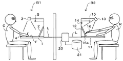
図1は本発明の一実施形態の記入ガイダンスシステムの概略を示す図である。図1において左側は記入者用ブースB1、右側は受付者用ブースB2である。記入者用ブースB1には、台(用紙載置手段)1が配置され、台1の上で記入者Cが図2(A)に示すフォーマット用紙Fに記入するようになっている。図2(A)に示すように、フォーマット用紙Fの右上にはバーコードBCが設けられている。このバーコードBCの位置は、全てのフォーマット用紙Fについて一定とされている。台1の上には、ディスプレイ(第1表示手段)2が記入者C側に向けて配置され、台1の上方にはフォーマット用紙Fを撮影するためのカメラ(記号読取手段、第1撮影手段)3が配置されている。また、台1の上面には、呼出ボタン(報知手段)4が取り付けられ、ディスプレイ2の上方にはマイク/スピーカ(音声伝達手段)5が配置されている。
【0015】
受付者用ブースB2には、台11が配置され、台11の上方には、ディスプレイ(第2表示手段)12が受付者R側に向けて配置されている。台1の上方にはディスプレイ12を撮影するためのカメラ(第2撮影手段)13が配置されている。カメラ13は、赤外光のみを透過させる赤外フィルタを備え、入射する光を可視光または赤外光に切り替えるようになっている。また、台11の上方には、呼出LED(報知手段)14とマイク/スピーカ(音声伝達手段)15が配置されている。
【0016】
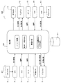
記入者用ブースB1および受付者用ブースB2の上記した機器は、回線Lによって制御部(制御手段)20に接続され、制御部20には記録部21が接続されている。図3は、制御部20およびその周辺機器の接続状態を示すブロック図である。カメラ3は、バーコードBCを含むフォーマット用紙Fを撮影し、制御部20はバーコードBCを画像解析して認識する。記録部21には、図2(B)で示すようなフォーマット用紙に記入例を記載した記入見本Sの画像データが蓄積されており、制御部20はバーコードによって特定された記入見本Sの画像データをディスプレイ2に出力して表示させる。また、記録部21には、音声ガイダンスのデータも蓄積されており、制御部20は、マイク/スピーカ5から音声ガイダンスを発声させる。なお、図3において符号6は、記入者Cがシステムを起動させるためのスタートボタンであり、台1に設けられている。
【0017】
記入者Cが表示された記入見本Sを見ても要領が判らない場合などには、呼出ボタン4を押して更なるガイドを要求する。これを受けて受付者Rが対応可能の信号を出すと、制御部20はカメラ3の画像を要求し、カメラ3は、フォーマット用紙Fを撮影し、その画像データを制御部20に出力する。制御部20は、その画像データを記録部21に格納するとともに、受付者用ブースB2のディスプレイ12に出力して表示させる。その際に、制御部20は、例えばブース番号などをカメラ画像に合成する。
【0018】
台11の上には、受付者Rがディスプレイ12上で指示するためのペンライト16が備えられている(図1参照)。ペンライト16の先端部には、LED等で構成される赤外光の発光部16aが設けられている。ペンライト16はディスプレイ12に発光部16aを押し付けて用いられるもので、ペンライト16には、発光部16aを押し付けた状態でONになる押圧スイッチが内蔵されている。
【0019】
カメラ13はディスプレイ12を撮影し、その画像データを制御部20に出力する。受付者Rは、ペンライト16の発光部16aを発光させてディスプレイ12上で移動させ、発光部16aが発する赤外光は、赤外フィルタを介してカメラ13で撮影される。カメラ13は撮影した赤外光の画像データを制御部20に出力する。
【0020】
制御部20は、一般的な画像解析の手法により、カメラ13で撮影したディスプレイ12に対応する二次元座標の領域(以下、この領域を仮想スクリーンと称する。)を生成する。仮想スクリーンの生成法としては、ディスプレイ12の四隅に赤外光の発光点を設けておき、発光させた各発光点をカメラ13により赤外フィルタを通して撮影する方法を採用することができる。この場合、制御部20は、画像データから各発光点の位置を認識し、発光点を結んだ矩形状の部分を仮想スクリーンとして認識する。
【0021】
ここで、ディスプレイ12はカメラ13に対して傾斜しているから、カメラ13の画角内において四隅の発光点を結ぶ形状(これはディスプレイ12に対応している)は台形状に歪んでいる。制御部20は、画像処理によって四隅の発光点の位置から歪みを補正した仮想スクリーンのXY座標を生成する。なお、このような座標の補正は、ディスプレイ12を白く発光させ、ディスプレイ12の枠の色とのコントラスト差によってディスプレイ12の表示領域を認識することを応用しても可能である。
【0022】
上記ディスプレイ12上(仮想スクリーン上)で移動するペンライト16の発光部16aの位置は、カメラ13で撮影され、その画像データは制御部20に入力される。制御部20は、仮想スクリーンの座標上での発光部16aの座標を逐一算出し、ディスプレイ12に表示している画像のデータと発光部16aの座標データを処理し、算出した発光部16aの座標にポイント画像等を合成する。なお、カメラ13にはズーム機能およびオートフォーカス機能を設けることもできる。
【0023】
制御部20は、上記のようにしてポイント画像等を合成した画像をディスプレイ2,12に表示させる。この場合において、制御部20は、ポイント画像がディスプレイ2上で移動するように制御するか、あるいは、発光する発光部16aをディスプレイ12上で動かすことにより連続した線を生成し、文字等を描くように制御する。上記いずれの機能を利用するかは、ペンライト16または台11上に設けたスイッチによって切り替えられる。なお、図3に示すように、記入者用ブースB1および受付者用ブースB2のその他の機器は、全て制御部20を介して互いに接続されている。
【0024】
B.実施形態の動作
(1)フォーマット用紙の特定
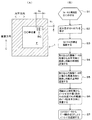
次に、上記記入ガイダンスシステムの動作について図4および図5を参照して説明する。図4(A)は記入者用ブースB1の台1の上面を示す。この図に示すように、台1の上面は黒色等の暗色とされている。まず、記入者Cがフォーマット用紙Fを台1の上に載置してスタートボタン6を押すと(ステップS1,S2)、カメラ3がフォーマット用紙Fを撮影する(ステップS3)。
【0025】
カメラ3が撮影した画像のデータは制御部20に出力される。制御部20は、取り込んだ画像データの右端から水平方向に検索し、台1とフォーマット用紙Fとのコントラストからフォーマット用紙の右端の位置を確定する(ステップS4)。また、制御部20は、取り込んだ画像データの上端から垂直方向に検索し、フォーマット用紙の上端の位置を確定する(ステップS5)。次に、制御部20は、フォーマット用紙Fの上端からY0の位置でX0の範囲のデータを水平方向に走査する(ステップS6)。そして、バーコードBCの画像データの白黒変化点等からバーコードBCを英数字にコード変換し、制御部20は、バーコードBCに基づく固有情報を認識する(ステップS7)。
【0026】
なお、この実施形態では、記入者Cがスタートボタン6を押してシステムを起動するようにしているが、台1の上方に反射型センサを配置しておき、台1にフォーマット用紙Fが載置されたことを検出してシステムを起動するようにしても良い。
【0027】
(2)記入ガイダンス
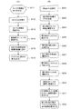
図5(A)は記入者Cに記入ガイダンスを行う手順を示すフローチャート、図5(B)は受付者Rが記入者Cに応対する手順を示すフローチャートである。図5(A)においてステップS11〜S14は、上記した図4(B)でのフォーマット用紙Fを特定する手順である。制御部20は、バーコードBCに基づく固有情報を認識すると、記録部21にアクセスし、固有情報が示すデータを読み出す。このデータは、記入見本Sの画像データおよび音声データであり、制御部20は、画像データをディスプレイ2に出力して表示させるとともに、音声データをマイク/スピーカ5に出力して音声ガイダンスを発声させる(ステップS15,S16)。これにより、記入者は、音声ガイダンスを聞き、また、ディスプレイ2に表示された記入見本Sを見ながらフォーマット用紙に記入することができる。
【0028】
ディスプレイ2に表示された記入見本Sを見ても記入の要領が判らない場合には、記入者Cは、呼出ボタン4を押す(ステップS22)。これにより、受付者用ブースB2の呼出LED14が点滅し(ステップS23)、受付者Rは、記入者Cが応対を求めていることを認識する。受付者Rが、対応準備ができて呼出LED14の点滅を停止させるボタンを押すと、呼出LED14の点滅が停止するとともに、その信号は制御部20に出力される。その信号を受けた制御部20は、カメラ3に台1上のフォーマット用紙Fを撮影させ(ステップS24)、カメラ3が撮影した画像を受付者ブースB2のディスプレイ12に表示させる(ステップS25)。
【0029】
受付者ブースB2に来た受付者Rは、マイク/スピーカ15によって記入者Cに対して応答し(ステップS26)、記入者Cは、マイク/スピーカ5によって受付者Rに不明点を質問する(ステップS27)。ここで、受付者Rが記入者Cに対してディスプレイ12を用いて説明する手順(ステップS28〜S32)を説明する。
【0030】
受付者Rは、カメラ13が撮影したディスプレイ12の画像をそのまま記入者用ブースB1のディスプレイ2に表示して説明することができる。この場合、受付者Rは、ディスプレイ12に表示されたフォーマット用紙Fに指やペンライト16等で指示したり、ディスプレイ12の上にフォーマット用紙Fを載置して実際に記入して見せたりすることができる。あるいは、フォーマット用紙Fに印紙や証紙を添付する場合には、それらの現物をカメラ13で撮影してディスプレイ2に表示することもできる。
【0031】
また、受付者Rは、ペンライト16の発光部16aを発光させ、その赤外光によってディスプレイ2にポイント指示することもでき、この方法と上記した方法のいずれを行うかは、ペンライト16や台11に設けたスイッチによって受付者Rが選択する。また、ポイント指示が選択された場合には、その瞬間にディスプレイ12に表示している画像を固定するとともに、その画像データを記録部21または制御部20が備えるメモリに格納する。つまり、ディスプレイ12に表示する画像は、カメラ3が撮影した画像ではなく、記録部21または制御部20が備えるメモリに格納したデータの画像となる。この場合、カメラ13には赤外フィルタが装着されるので、カメラ13は、例えばディスプレイ12の四隅に設けた赤外光の発光点と、ペンライト16の発光部16aとが発する赤外光を撮影する(ステップS29)。
【0032】
ディスプレイ12上で移動するペンライト16の発光部16aの位置は、カメラ13で撮影され、その画像データは制御部20に入力される。制御部20は、仮想スクリーンの座標上での発光部16aの座標を逐一算出する。そして、制御部20は、座標が算出される毎にディスプレイ12に表示している固定された画像のデータを記録部21等から読み出し、その画像データと発光部16aの座標データを処理し、算出した発光部16aの座標にポイント画像等を合成する(ステップS31)。次いで、制御部20は、ポイント画像等を合成した画像をディスプレイ2,12に表示させる(ステップS32)。ここで、発光する発光部16aをディスプレイ12上で動かすことにより連続した線を生成する場合には、合成した画像のデータを記録部21等に格納した画像データに上書きする。また、そのような上書きを行わない場合には、ポイント画像はディスプレイ2,12上で移動する。
【0033】
上記記入ガイダンスシステムにおいては、記入者Cが台1に載置したフォーマット用紙Fの記入の補助となる音声ガイダンスがマイク/スピーカ5から提供され、記入見本Sがディスプレイ2に表示されるから、記入者Cは、それらガイダンス情報に従ってフォーマット用紙Fに記入することができる。したがって、記入者Cは記入見本を探す必要がなく、しかもボタン操作も不要であることから便利であり、サービスを向上させることができる。また、フォーマットが変更となった場合には記録部21に格納するデータを変更すれば良いから、その対応が容易である。
【0034】
特に、上記実施形態では、マイク/スピーカ5,15によって記入者Cと受付者Rとが会話することができから、受付者Rが記入者Cの所へ行かないでも記入の説明ができるとともに、記入者Cにとっても受付者Rが来るまで待たなくて済むという利点がある。したがって、記入ミス防止により受付業務の効率化が図られるとともに、一層のサービス向上につながる。
【0035】
また、上記実施形態では、記入者Cが台1に載置したフォーマット用紙Fの画像がディスプレイ12に表示されるから、受付者Rは記入者Cにとって不明な点が理解し易くなり、記入者Cに対する説明を的確に行うことができる。さらに、上記実施形態では、受付者Rがディスプレイ12上でペンライト16の発光部16aを発光させることにより、ディスプレイ2の画像にポイント画像が合成されるから、記入者Cが記入したフォーマット用紙F上にポイント指示したり文字などを重ね書きすることができる。したがって、受付者Rによる説明が判り易く、記入ミスをさらに効果的に防止することができる。
【0036】
図6は上記実施形態の応用例を示す図である。この応用例では、複数の記入者用ブースB1と2つの受付者用ブースB2とを回線Lで接続したものである。記入者用ブースB1および受付者用ブースB2には、上記と同等の機器が備えられ、また、それらの間には制御部20と記録部21とが介装されている。このような記入ガイダンスシステムでは、上記実施形態と同等の効果が得られることは勿論のこと、複数の記入者に対して少人数の受付者が応対することができ、受付者の人員を減らすことができる。また、受付者用ブースB2を任意の場所に設置して集中的に対応することができるという利点もある。
【0037】
なお、この応用例では、受付者用ブースB2に記入者からの呼出が集中した場合の措置を講ずることが望まれる。たとえば、記入者が呼出スイッチを押したときに受付者用ブースB2が全て使用中のときは、ディスプレイ2に「しばらくお待ち下さい」といったメッセージを表示させ、受付者の応対が終わったときに台11上のスイッチを押すと、次の記入者との間でマイク/スピーカ5,15が接続されるようにする。
【0038】
【発明の効果】
以上説明したように、本発明によれば、フォーマット用紙へ記入するに際しての種々の煩雑さを解消することができるとともに、フォーマットの変更にも柔軟に対応することができ、また、記入者に適切に応答することができ、しかも、受付者の人員を削減することができる等の効果が得られる。
【図面の簡単な説明】
【図1】 本発明の実施形態の記入ガイダンスシステムの概略を示す側面図である。
【図2】 (A)はフォーマット用紙を示す平面図であり、(B)は記入見本を示す平面図である。
【図3】 実施形態の記入ガイダンスシステムを示すブロック図である。
【図4】 フォーマット用紙のバーコードを読み取る手順を示す平面図(A)およびフローチャート(B)である。
【図5】 (A)は記入ガイダンスの手順を示すフローチャート、(B)は記入者が受付者と連絡する際の手順を示すフローチャートである。
【図6】 本発明の実施形態の応用例を示す図である。
【符号の説明】
1…台(用紙載置手段)、
2…ディスプレイ(ガイダンス情報提供手段、第1表示手段)、
3…カメラ(記号読取手段、第1撮影手段)、
4…呼出ボタン(報知手段)、5…マイク/スピーカ(音声伝達手段)、
12…ディスプレイ(第2表示手段)、13…カメラ(第2撮影手段)、
14…呼出LED(報知手段)、15…マイク/スピーカ(音声伝達手段)、
16…ペンライト(指示マーク)、20…制御部(制御手段)、C…記入者、
F…フォーマット用紙、R…受付者、S…記入見本。[0001]
BACKGROUND OF THE INVENTION
The present invention relates to an entry guidance system for displaying an example of entry of a format sheet such as an application form or an application form at a government office, a bank, a store, a railway window or the like.
[0002]
[Prior art]
In places such as those mentioned above, it is often the case that the entry sample is displayed on the table for filling in the format sheet or the entry sample is laid under the glass plate on the table. Then, the user (entry person) enters predetermined items on the format sheet while referring to the entry sample.
[0003]
[Problems to be solved by the invention]
However, when filling in the format sheet as described above, there are the following inconveniences.
1) When there are many types of format paper, the format paper and the entry sample may be placed in different places, and the entrant must search for the entry sample.
2) If the entry details are unknown, the entry person must go to the reception desk or the information desk.
3) The receptionist will be able to recognize entry mistakes and omissions for the first time at the counter, etc., so it is necessary for the entry person to complete the entry again.
4) When the entry method or format is changed, it is necessary to exchange all entry samples.
[0004]
Therefore, an object of the present invention is to provide an entry guidance system that can eliminate various complications when filling in a format sheet and can flexibly cope with a change in format.
[0005]
[Means for Solving the Problems]
An entry guidance system according to the present invention includes a format sheet to which a symbol indicating the format type is attached, a sheet placing means for placing the format sheet and an entry person filling in the format sheet, and a sheet placing means. Or guidance information providing means provided in the vicinity thereof, symbol reading means for reading the symbols attached to the format paper, and guidance information for assisting entry on the format paper specified by the symbols read by the symbol reading means And control means for providing guidance information from the guidance information providing means.
[0006]
In the entry guidance system configured as described above, since the guidance information providing means provides the guidance information for filling in the format paper placed on the paper placement means by the entry person, the entry person can use the format paper according to the guidance information. You can fill in. Therefore, the writer does not need to search for a sample entry, and the button operation is unnecessary, which is convenient and can improve the service. Further, when the format is changed, the guidance information (data) may be changed, so that the correspondence can be easily performed.
[0007]
Here, the guidance information providing means can be composed of a speaker that provides audio information, and a first display means for displaying a sample entry in which an example of entry is described on the format sheet, and these can be used together. You can also.
[0008]
The symbol reading unit includes a first photographing unit that photographs the format paper placed on the paper placing unit, and a control unit that analyzes the image of the format paper photographed by the first photographing unit and identifies the symbol. Is preferred. As the first photographing means, for example, a camera equipped with a CCD and a lens can be used. In this case, the symbol may be a barcode, an array of characters or figures, and the barcode reader may be used as the symbol reading means when the barcode is used. The bar code reader may be of a type in which the writer traces the bar code, or a bar code reader fixed to the paper placing means.
[0009]
Even if you get guidance information, you may not know how to fill out the format sheet. Therefore, it is preferable to provide notification means for the writer to notify the receptionist. Thereby, the receptionist can go to the place of the writer and explain the entry. Further, it is more preferable to provide a voice transmission means for carrying out a conversation between the acceptor and the writer. By configuring in this manner, there is an advantage that the receptionist can explain the entry without going to the place of the entry person, and the entry person does not have to wait until the reception person comes. Therefore, the efficiency of the reception work can be improved by preventing entry errors, and the service can be further improved.
[0010]
It is more preferable to include second display means for displaying the image of the format paper photographed by the first photographing means for the recipient to visually recognize. By providing such a second display means, it becomes easier for the acceptor to understand the unclear points for the writer, so that the writer can be accurately explained.
[0011]
It is preferable that an acceptor is provided with an instruction mark for operating on or near the screen of the second display means, and a second photographing means for photographing the instruction mark. In this case, the control means calculates the coordinates of the instruction mark on the screen of the second display means, and synthesizes a predetermined instruction image with the coordinates of the image displayed by the second display means corresponding to the coordinates of the instruction mark. Display on the first display means. As a result, the acceptor can overwrite characters and the like on the format sheet filled in by the entry person with the instruction mark, and the entry person can visually recognize it on the first display means. Therefore, the explanation by the receptionist is easy to understand, and entry errors can be prevented more effectively. In this case, the instruction image can be one that moves on the screen or one that represents the locus of movement as a continuous line. Further, if an image obtained by synthesizing the instruction image is also displayed on the second display means, it is convenient for the acceptor to confirm the position of the instruction mark.
[0012]
The second photographing means can be configured to photograph an image displayed by the second display means, and the control means can display the image photographed by the second photographing means on the first display means. In this case, the acceptor can instruct and explain the format paper displayed on the second display means with a finger or a writing instrument, or can photograph and explain the actual object such as a stamp or a certificate.
[0013]
Provide multiple devices on the entry side as described above, connect these devices to the devices on the smaller number of recipients, so that a small number of recipients can respond to multiple entries Then it is more efficient. Thereby, a small number of acceptors can respond intensively to a plurality of writers, and the number of acceptors can be reduced.
[0014]
DETAILED DESCRIPTION OF THE INVENTION
Hereinafter, an embodiment of the present invention will be described with reference to the drawings.
A. Configuration of Embodiment FIG. 1 is a diagram showing an outline of an entry guidance system according to an embodiment of the present invention. In FIG. 1, the left side is an entry booth B1, and the right side is a receptionist booth B2. A stand (paper placing means) 1 is arranged in the booth B1 for the writer, and the writer C fills in the format paper F shown in FIG. As shown in FIG. 2A, a barcode BC is provided at the upper right of the format paper F. The position of the barcode BC is fixed for all the format sheets F. A display (first display means) 2 is arranged on the table 1 toward the writer C side, and a camera (symbol reading means, first imaging means) for photographing the format paper F above the table 1. ) 3 is arranged. In addition, a call button (notification unit) 4 is attached to the upper surface of the table 1, and a microphone / speaker (speech transmission unit) 5 is disposed above the
[0015]
A
[0016]
The above-described devices of the booth B1 for the entrant and the booth B2 for the acceptor are connected to the control unit (control means) 20 via the line L, and the
[0017]
If, for example, the point of entry S is not clear from the displayed entry sample S, the call button 4 is pressed to request further guidance. In response to this, when the acceptor R issues a signal indicating that it can respond, the
[0018]
A
[0019]
The
[0020]
The
[0021]
Here, since the
[0022]
The position of the
[0023]
The
[0024]
B. Operation of Embodiment (1) Identification of Format Sheet Next, the operation of the entry guidance system will be described with reference to FIG. 4 and FIG. FIG. 4A shows the upper surface of the stand 1 of the booth B1 for entry. As shown in this figure, the upper surface of the table 1 is dark color such as black. First, when the writer C places the format paper F on the table 1 and presses the start button 6 (steps S1 and S2), the
[0025]
Data of an image captured by the
[0026]
In this embodiment, the writer C presses the start button 6 to activate the system. However, a reflective sensor is arranged above the table 1 and the format sheet F is placed on the table 1. The system may be activated by detecting this.
[0027]
(2) Entry Guidance FIG. 5 (A) is a flowchart showing a procedure for giving entry guidance to the entrant C, and FIG. 5 (B) is a flowchart showing a procedure for the receptionist R to respond to the entrant C. In FIG. 5A, steps S11 to S14 are procedures for specifying the format paper F in FIG. 4B described above. When recognizing the unique information based on the barcode BC, the
[0028]
If the entry procedure S is not understood from the entry sample S displayed on the
[0029]
The receptionist R who has come to the receptionist booth B2 responds to the writer C by the microphone / speaker 15 (step S26), and the writer C asks the receptionist R about the unclear point by the microphone / speaker 5 (step S26). Step S27). Here, the procedure (steps S28 to S32) that the acceptor R explains to the writer C using the
[0030]
The receptionist R can display and explain the image of the
[0031]
The receptionist R can also emit light from the light-emitting
[0032]
The position of the
[0033]
In the above entry guidance system, voice guidance is provided from the microphone /
[0034]
In particular, in the above embodiment, since the writer C and the receiver R can talk with each other through the microphones /
[0035]
In the above embodiment, since the image of the format paper F placed on the table 1 by the writer C is displayed on the
[0036]
FIG. 6 is a diagram showing an application example of the above embodiment. In this application example, a plurality of entry booths B1 and two receptionist booths B2 are connected by a line L. The booth B1 for the entrant and the booth B2 for the recipient are equipped with the same devices as described above, and the
[0037]
In this application example, it is desirable to take measures when calls from writers are concentrated in the booth B2 for acceptors. For example, when the entrant presses the call switch and the receptionist booth B2 is all in use, a message such as “Please wait for a while” is displayed on the
[0038]
【The invention's effect】
As described above, according to the present invention, it is possible to eliminate various complications when filling in a format sheet, to flexibly deal with a change in format, and to be suitable for the entry person. In addition, it is possible to obtain an effect such that the number of reception staff can be reduced.
[Brief description of the drawings]
FIG. 1 is a side view showing an outline of an entry guidance system according to an embodiment of the present invention.
FIG. 2A is a plan view showing a format sheet, and FIG. 2B is a plan view showing an entry sample.
FIG. 3 is a block diagram illustrating an entry guidance system according to the embodiment.
FIG. 4 is a plan view (A) and a flowchart (B) showing a procedure for reading a barcode on a format sheet.
FIG. 5A is a flowchart showing a procedure of entry guidance, and FIG. 5B is a flowchart showing a procedure when the writer contacts the receptionist.
FIG. 6 is a diagram illustrating an application example of an embodiment of the present invention.
[Explanation of symbols]
1 ... stand (paper placing means),
2. Display (guidance information providing means, first display means),
3. Camera (symbol reading means, first photographing means),
4 ... Call button (notification means), 5 ... Microphone / speaker (voice transmission means),
12 ... Display (second display means), 13 ... Camera (second photographing means),
14 ... Call LED (notification means), 15 ... Microphone / speaker (voice transmission means),
16 ... penlight (instruction mark), 20 ... control unit (control means), C ... filler,
F ... Format paper, R ... Receiver, S ... Entry sample.
Claims (9)
このフォーマット用紙を載置して記入者が上記フォーマット用紙に記入するための用紙載置手段と、
上記用紙載置手段またはその近傍に設けられたガイダンス情報提供手段と、
上記フォーマット用紙に付された記号を読み取る記号読取手段と、
上記記号読取手段によって読み取られた記号により特定されるフォーマット用紙への記入の補助となるガイダンス情報を上記ガイダンス情報提供手段から提供させる制御手段と
を備えたことを特徴とする記入ガイダンスシステム。A format sheet with a symbol indicating the format type, and
A paper placing means for placing the formatted paper and allowing the writer to fill in the formatted paper;
Guidance information providing means provided at or near the paper placing means,
Symbol reading means for reading a symbol attached to the format paper;
An entry guidance system comprising control means for providing guidance information from the guidance information providing means to assist entry in a format sheet specified by a symbol read by the symbol reading means.
前記制御手段は、上記第2表示手段の画面上での上記指示マークの座標を算出し、この指示マークの座標に対応する上記第2表示手段が表示する画像の座標に所定の指示画像を合成して、上記第2表示手段に表示するとともに、上記第1表示手段に表示することを特徴とする請求項6に記載の記入ガイダンスシステム。An instruction mark for the receiver to operate on or near the screen of the second display means; and a second imaging means for photographing the instruction mark;
The control means calculates the coordinates of the instruction mark on the screen of the second display means, and synthesizes a predetermined instruction image with the coordinates of the image displayed by the second display means corresponding to the coordinates of the instruction mark. The entry guidance system according to claim 6, wherein the entry guidance system displays on the second display means and on the first display means.
Priority Applications (1)
| Application Number | Priority Date | Filing Date | Title |
|---|---|---|---|
| JP2002221146A JP4055893B2 (en) | 2002-07-30 | 2002-07-30 | Entry guidance system |
Applications Claiming Priority (1)
| Application Number | Priority Date | Filing Date | Title |
|---|---|---|---|
| JP2002221146A JP4055893B2 (en) | 2002-07-30 | 2002-07-30 | Entry guidance system |
Publications (2)
| Publication Number | Publication Date |
|---|---|
| JP2004062587A JP2004062587A (en) | 2004-02-26 |
| JP4055893B2 true JP4055893B2 (en) | 2008-03-05 |
Family
ID=31941547
Family Applications (1)
| Application Number | Title | Priority Date | Filing Date |
|---|---|---|---|
| JP2002221146A Expired - Fee Related JP4055893B2 (en) | 2002-07-30 | 2002-07-30 | Entry guidance system |
Country Status (1)
| Country | Link |
|---|---|
| JP (1) | JP4055893B2 (en) |
Families Citing this family (5)
| Publication number | Priority date | Publication date | Assignee | Title |
|---|---|---|---|---|
| JP4678621B2 (en) * | 2005-02-16 | 2011-04-27 | 株式会社フィクス | Will note |
| JP4270240B2 (en) | 2006-08-14 | 2009-05-27 | コニカミノルタビジネステクノロジーズ株式会社 | Image display device, image display method, and image display program |
| JP5691736B2 (en) * | 2011-03-29 | 2015-04-01 | ブラザー工業株式会社 | Reader |
| JP2013214260A (en) * | 2012-04-04 | 2013-10-17 | Seiko Epson Corp | Image input device, image input system and control method of image input device |
| JP6054335B2 (en) * | 2014-05-28 | 2016-12-27 | 株式会社両毛システムズ | Family register window business support device and family register window business support program |
-
2002
- 2002-07-30 JP JP2002221146A patent/JP4055893B2/en not_active Expired - Fee Related
Also Published As
| Publication number | Publication date |
|---|---|
| JP2004062587A (en) | 2004-02-26 |
Similar Documents
| Publication | Publication Date | Title |
|---|---|---|
| US7176881B2 (en) | Presentation system, material presenting device, and photographing device for presentation | |
| US8049680B2 (en) | Method for improving vision of a low-vision person and viewing aid | |
| US6037915A (en) | Optical reproducing system for multimedia information | |
| US7762672B2 (en) | Data presentation apparatus and operation method of terminal | |
| US7015969B2 (en) | Hand-held image capture apparatus with scanning arrangement | |
| US10511812B2 (en) | Information displaying system and information providing terminal | |
| US10582153B2 (en) | Information displaying system and information providing terminal | |
| US20030081014A1 (en) | Method and apparatus for assisting the reading of a document | |
| JP4055893B2 (en) | Entry guidance system | |
| TW201225641A (en) | Imaging inspection device of 3D camera module and imaging inspection method, imaging inspection control program, imaging correction method, imaging correction control program, readable recording medium, and electronic information apparatus thereof | |
| EP1042909A1 (en) | A digital handheld keyboard oriented device with multikey data and control input, display, wireless communication and data processing and a camera feeding the communication | |
| JP7281904B2 (en) | image capture device | |
| CN114613069B (en) | Intelligent self-service terminal and intelligent auxiliary method thereof | |
| JP4561397B2 (en) | Image acquisition method and camera device | |
| JP2005114996A (en) | Projector device and writing acquiring method | |
| JP2006237937A (en) | Image recording method and camera device | |
| JPH05100645A (en) | Integrated external information fetching/processing/ display device | |
| JP4145070B2 (en) | Presentation method using document camera device | |
| JP4407668B2 (en) | Overhead scanner | |
| JP2004198817A (en) | Presentation device | |
| JP7416231B2 (en) | Installation support device, installation support method, and program | |
| CN110751113B (en) | Scanning method and electronic equipment | |
| JP2005252523A (en) | Device and method for presenting material | |
| US20060016890A1 (en) | Automatic planar image capture device | |
| JP2005167784A (en) | Material presenting apparatus |
Legal Events
| Date | Code | Title | Description |
|---|---|---|---|
| A621 | Written request for application examination |
Free format text: JAPANESE INTERMEDIATE CODE: A621 Effective date: 20050420 |
|
| A977 | Report on retrieval |
Free format text: JAPANESE INTERMEDIATE CODE: A971007 Effective date: 20071114 |
|
| TRDD | Decision of grant or rejection written | ||
| A01 | Written decision to grant a patent or to grant a registration (utility model) |
Free format text: JAPANESE INTERMEDIATE CODE: A01 Effective date: 20071119 |
|
| A61 | First payment of annual fees (during grant procedure) |
Free format text: JAPANESE INTERMEDIATE CODE: A61 Effective date: 20071205 |
|
| R150 | Certificate of patent or registration of utility model |
Ref document number: 4055893 Country of ref document: JP Free format text: JAPANESE INTERMEDIATE CODE: R150 Free format text: JAPANESE INTERMEDIATE CODE: R150 |
|
| FPAY | Renewal fee payment (event date is renewal date of database) |
Free format text: PAYMENT UNTIL: 20101221 Year of fee payment: 3 |
|
| FPAY | Renewal fee payment (event date is renewal date of database) |
Free format text: PAYMENT UNTIL: 20101221 Year of fee payment: 3 |
|
| S111 | Request for change of ownership or part of ownership |
Free format text: JAPANESE INTERMEDIATE CODE: R313113 |
|
| FPAY | Renewal fee payment (event date is renewal date of database) |
Free format text: PAYMENT UNTIL: 20101221 Year of fee payment: 3 |
|
| R350 | Written notification of registration of transfer |
Free format text: JAPANESE INTERMEDIATE CODE: R350 |
|
| FPAY | Renewal fee payment (event date is renewal date of database) |
Free format text: PAYMENT UNTIL: 20101221 Year of fee payment: 3 |
|
| FPAY | Renewal fee payment (event date is renewal date of database) |
Free format text: PAYMENT UNTIL: 20111221 Year of fee payment: 4 |
|
| R250 | Receipt of annual fees |
Free format text: JAPANESE INTERMEDIATE CODE: R250 |
|
| FPAY | Renewal fee payment (event date is renewal date of database) |
Free format text: PAYMENT UNTIL: 20111221 Year of fee payment: 4 |
|
| FPAY | Renewal fee payment (event date is renewal date of database) |
Free format text: PAYMENT UNTIL: 20121221 Year of fee payment: 5 |
|
| R250 | Receipt of annual fees |
Free format text: JAPANESE INTERMEDIATE CODE: R250 |
|
| FPAY | Renewal fee payment (event date is renewal date of database) |
Free format text: PAYMENT UNTIL: 20121221 Year of fee payment: 5 |
|
| FPAY | Renewal fee payment (event date is renewal date of database) |
Free format text: PAYMENT UNTIL: 20131221 Year of fee payment: 6 |
|
| R250 | Receipt of annual fees |
Free format text: JAPANESE INTERMEDIATE CODE: R250 |
|
| R250 | Receipt of annual fees |
Free format text: JAPANESE INTERMEDIATE CODE: R250 |
|
| R250 | Receipt of annual fees |
Free format text: JAPANESE INTERMEDIATE CODE: R250 |
|
| R250 | Receipt of annual fees |
Free format text: JAPANESE INTERMEDIATE CODE: R250 |
|
| R250 | Receipt of annual fees |
Free format text: JAPANESE INTERMEDIATE CODE: R250 |
|
| R250 | Receipt of annual fees |
Free format text: JAPANESE INTERMEDIATE CODE: R250 |
|
| R250 | Receipt of annual fees |
Free format text: JAPANESE INTERMEDIATE CODE: R250 |
|
| R250 | Receipt of annual fees |
Free format text: JAPANESE INTERMEDIATE CODE: R250 |
|
| R250 | Receipt of annual fees |
Free format text: JAPANESE INTERMEDIATE CODE: R250 |
|
| LAPS | Cancellation because of no payment of annual fees |