JP4055321B2 - Fuel injection valve and internal combustion engine equipped with the same - Google Patents
Fuel injection valve and internal combustion engine equipped with the same Download PDFInfo
- Publication number
- JP4055321B2 JP4055321B2 JP2000067131A JP2000067131A JP4055321B2 JP 4055321 B2 JP4055321 B2 JP 4055321B2 JP 2000067131 A JP2000067131 A JP 2000067131A JP 2000067131 A JP2000067131 A JP 2000067131A JP 4055321 B2 JP4055321 B2 JP 4055321B2
- Authority
- JP
- Japan
- Prior art keywords
- fuel
- spray
- fuel injection
- outlet opening
- injection valve
- Prior art date
- Legal status (The legal status is an assumption and is not a legal conclusion. Google has not performed a legal analysis and makes no representation as to the accuracy of the status listed.)
- Expired - Fee Related
Links
Images


Classifications
-
- F—MECHANICAL ENGINEERING; LIGHTING; HEATING; WEAPONS; BLASTING
- F02—COMBUSTION ENGINES; HOT-GAS OR COMBUSTION-PRODUCT ENGINE PLANTS
- F02B—INTERNAL-COMBUSTION PISTON ENGINES; COMBUSTION ENGINES IN GENERAL
- F02B75/00—Other engines
- F02B75/12—Other methods of operation
- F02B2075/125—Direct injection in the combustion chamber for spark ignition engines, i.e. not in pre-combustion chamber
-
- Y—GENERAL TAGGING OF NEW TECHNOLOGICAL DEVELOPMENTS; GENERAL TAGGING OF CROSS-SECTIONAL TECHNOLOGIES SPANNING OVER SEVERAL SECTIONS OF THE IPC; TECHNICAL SUBJECTS COVERED BY FORMER USPC CROSS-REFERENCE ART COLLECTIONS [XRACs] AND DIGESTS
- Y02—TECHNOLOGIES OR APPLICATIONS FOR MITIGATION OR ADAPTATION AGAINST CLIMATE CHANGE
- Y02T—CLIMATE CHANGE MITIGATION TECHNOLOGIES RELATED TO TRANSPORTATION
- Y02T10/00—Road transport of goods or passengers
- Y02T10/10—Internal combustion engine [ICE] based vehicles
- Y02T10/12—Improving ICE efficiencies
Landscapes
- Combustion Methods Of Internal-Combustion Engines (AREA)
- Fuel-Injection Apparatus (AREA)
Description
【0001】
【発明の属する技術分野】
本発明は、内燃機関に燃料を噴射する燃料噴射弁に係り、点火性および燃焼性に優れた燃料噴霧を形成する技術に関する。
【0002】
【従来の技術】
エンジンの吸気管内に燃料を噴射する吸気管内燃料噴射装置に対して、燃焼室内に直接燃料を噴射する筒内燃料噴射装置が知られている。
【0003】
このような、筒内噴射ガソリンエンジンとして、特開平6−146886 号公報に記載されたものがある。この従来技術では、燃料噴射弁の取付け位置に対する配慮と、吸気開口端から上方に延びる吸気ポートにより燃焼室内に縦渦の吸気流れ(タンブル流)を形成する構成として、理論混合気よりも希薄な燃料で燃焼を安定して行い、燃費を改善するというものである。
【0004】
【発明が解決しようとする課題】
上記の従来技術では、以下に述べるような、点火性(着火性)と燃焼性(未燃ガス排出量低減)を共に向上させ得るような噴霧形状或いは噴霧構造に対しては、必ずしも十分な配慮がなされていなかった。
【0005】
燃料噴射弁より噴射される噴霧の最適化には、以下の様な特性を考慮する必要がある。第一は噴霧形状であり、噴霧の広がり角度や到達距離が因子となる。第二は噴霧粒径であり、大粒子の個数をできるかぎり少なくして粒径分布の均一化を図る必要がある。第三は噴霧構造であり、噴霧される燃料粒子の空間的分布を適正化する必要がある。
【0006】
これらの噴霧特性が内燃機関の燃焼特性にどのように関与するかについて、実験解析により検討した結果、以下のことが明らかになった。点火性向上のためには、点火装置回りの燃料粒子分布を多くして、可燃濃度の混合気の分布を高くすることが有効である。一方、ピストン方向への燃料粒子分布を少なくさせると、燃焼の未燃ガス成分(HC、CO)が減少する傾向にあり、燃焼性が向上する。さらに、エンジン回転数の低回転から高回転までの広い領域で燃焼安定性を得るには、筒内の圧力変化によって噴霧形状が変化しないことが望ましい。なぜならば、インジェクタと点火装置の幾何学的な位置関係は固定されているため、常に点火装置へ適切な濃度の噴霧を供給するためには、噴霧の広がりは一定である事が重要だからである。言い換えれば、従来のインジェクタが噴射する噴霧は、筒内圧力が低い時には噴霧が広がり、筒内圧が増加すると噴霧が潰れる傾向があった。この場合、筒内圧が比較的高い状態を基準にして、インジェクタと点火装置の配置を決めると、筒内圧が低い時に、筒内のシリンダ上面や側面あるいは、ピストンヘッドに燃料が付着し易くなり、一方、筒内圧が比較的低い状態を基準にすると、筒内圧が高くなった時に点火装置に燃焼に適切な噴霧が到達し難くなる傾向があった。
【0007】
本発明では、内燃機関の点火性を良好とし、燃焼の未燃ガス成分の排出量を低減するのに適した噴霧を実現することを目的とする。
【0008】
【課題を解決するための手段】
上記目的を達成するために、筒内の圧力変化に対して形状の変化し難い噴霧を生成する。このために、点火装置方向へ混合気を収斂し、ピストン方向への燃料粒子を希薄にした噴霧を生成する。このとき、燃料粒子が希薄になった(場合によっては、燃料分子がなくなった)部分から、噴霧外の空気を噴霧内に誘引することができる。これによって、噴霧内外の圧力差を小さくすることができ、噴霧を潰れにくくする。
【0009】
具体的には、燃料噴射弁に設けられ、燃料を噴射する噴射孔の出口部において、噴射孔を形成する壁面の一部を取り除くことにより、噴霧の流れの拘束を解き、拘束を解いた側で濃く、拘束した側で希薄な偏向噴霧を形成するとよい。このとき、拘束力を非線形に変化させることが望ましい。
【0010】
内燃機関では、点火装置側に濃い噴霧が形成され、ピストン側に薄い噴霧が形成されるように、上記の燃料噴射弁を配置するとよい。
【0011】
【発明の実施の形態】
本発明の一実施例を図1乃至図6を参照して説明する。以下の説明において、弁軸線(弁軸心)を含み、かつ弁軸線に平行な面を縦断面と呼び、弁軸線に直行する平面を横断面と呼ぶこととする。
【0012】
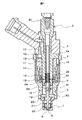
電磁式燃料噴射弁1は、コントロ−ルユニットにより演算されたデュ−ティのON−OFF信号によりシ−ト部の開閉を行うことにより燃料を噴射する。磁気回路は、ヨ−ク3、ヨ−ク3の開口端を閉じる栓体部2aとヨ−ク3の中心部に延びる柱状部2bとからなるコア2及びコア2に空隙を隔てて対面するアンカー4とからなる。柱状部2bの中心には、磁性材料製のアンカー4とロッド5とこのロッド5に接合されたボ−ル6とからなる弁体40を、シ−ト面9に押圧するように挿入した、弾性部材としてのスプリング10を保持するための穴4Aが設けてある。シート面9は噴射孔8と共に、かつ噴射孔8の上流側に位置するようにノズル部材7に形成されている。スプリング10の上端は、セット荷重を調整するためにコア2の中心に挿通されたスプリングアジャスタ11の下端に当接している。コア2の柱状部2b側とヨ−ク3の弁体40側で対面する隙間部には、コイル14側へ燃料が流出するのを防ぐために、両者間に機械的に固定されるシ−ルリング12が設けられている。磁気回路を励磁するコイル14はボビン13に巻かれ、その外周をプラスチック材でモ−ルドされている。これらから成るコイル組立体15の端子17は、コア2の栓体部(つば)2aに設けた穴16に挿入されている。この端子17は、図示しないコントロ−ルユニットの端子と結合される。
【0013】
ヨ−ク3には、弁体40を受容するプランジャ受容部18が開けられており、さらにプランジャ受容部18の径より大径でそこにストッパ19及びノズル部材7を受容するノズル受容部20がヨ−ク3先端まで貫設されている。ロッド5のアンカー4側には燃料の通過を許す空洞部5Aが設けてある。この空洞部5Aには燃料の流出口5Bが設けてある。弁体40はアンカー4の外周がシ−ルリング12の内周に当接することでその軸方向の動きを案内されるとともに、ボ−ル6又はロッド5のボ−ル6側端部近傍を、燃料旋回素子22の内周面23でガイドされている。燃料旋回素子22はノズル部材7が形成する中空部に挿入され、シート面9の上流側で、内壁21と接して位置決めされている。本実施例では、ノズル部材7を円筒状の側壁部(周壁部)72と端面(底面)71とを有するように一つの部材で構成している。この場合、ノズル部材7は燃料旋回素子及び弁体の一部を収納するハウジングを構成する。
【0014】
また、弁体40のストロ−ク(図1では軸上方への移動量)は、ロッド5の首部の受け面5Cとストッパ19間の空隙の寸法で設定される。なお、フィルタ−24は燃料中や配管中のゴミや異物がボール6とシート面9との間のバルブシ−ト側への侵入を防ぐために設けられている。
【0015】
次に、図2を参照しながら、本実施例のL型切り欠き面構造のノズル部材7について説明する。
【0016】
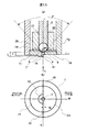
噴射孔8は、その中心が弁体の軸線(弁軸心)Jと一致し、かつ壁面が軸線Jと平行に形成されている。噴射孔8の出口開口が形成されるノズル先端面7Aには、軸線Jに直交する面7Bと軸線Jに略平行な面A1、A2とによって構成されるL型切り欠き部が形成されている。このとき、切り欠かれた部分の噴射孔幅はW、噴射孔長さは最も深く切り欠かれた部分でL、切り欠かれていない(最も切り欠きの少ない)部分でL′に形成され、ノズル部材7の先端面は噴射孔8を挟むように形成された軸線Jに垂直な2つの平面7A,7Bと、これらの平面を繋ぐ軸線Jに平行な面A1で形成されている。また、ノズル先端突起部7Aの内壁A2と噴射孔8の縁との間には距離C1のクリアランスを設けている。すなわち、内壁A2は、噴射孔8の出口開口のさらに下流側に設けられ、噴射孔8の出口開口縁の少なくとも一部の外側を囲むように形成されている。
【0017】
上記構成によれば、噴射孔8の出口開口面は、段差を有する平面7A,7B上に、段差を有して形成されることになる。
【0018】
上記の切り欠き部は、噴射孔8の周方向で、噴霧の拘束力を非線形に変化させることが望ましい。好ましくは、ステップ状に変化させることが望ましい。このために、本実施例の燃料噴射弁は、以下の構成を有すると言える。
【0019】
(1)噴射孔8の中心軸線を含みかつ中心軸線に平行な断面と、噴射孔8の出口開口を形成する縁との2つの交点を、中心軸線に沿う方向にずらすと共に、一方の交点から他方の交点に至る途中で、出口開口を形成する縁に段差が形成されている、
(2)このとき、2つの交点から段差部に至るまでの間で、出口開口を形成する2つの縁は、上記の断面に垂直な方向から見たときに、互いに平行になっている、
(3)また、出口開口を形成する縁は、段差部で、中心軸線に沿う方向に変化するように形成されている、
(4)噴射孔8の出口開口面は、噴射孔8の中心軸線方向に段差を有するように形成されている、
(5)噴射孔8を形成する通路壁の長さが、噴射孔8の周方向で非線形に変化する部分を有して変化するように、噴射孔8の出口開口部に段差が設けられている、
(6)噴射孔8の出口開口には、噴射孔の中心軸線に略平行な切れ込みが形成され、この切れ込みから片側の壁面が取り除かれることにより、段差が形成されている、
(7)噴射孔8の出口開口が形成されるノズル先端面に段差が形成されることにより、出口開口面に段差が形成されている、
(8)噴射孔8を形成する通路壁面長さが噴射孔8の周方向で変化するように、噴射孔8の出口開口を形成する縁に、噴射孔8の中心軸線方向の段差が形成され、燃料噴射弁への燃料入口部で、燃料に1.0〜20MPaの圧力を付与して噴射する。
【0020】
図2(a)の構成において、噴霧には次のような特徴がある。
【0021】
(イ)噴射孔8を形成する通路壁の切り欠かれた側では、噴霧の分布量(混合気の分布量)が多い、
(ロ)切り欠かれた側から噴射される噴霧は運動エネルギーが大きいため、噴霧の粒径が小さくなる。
【0022】
上記(イ)及び(ロ)の効果により、着火性が良くなり、燃費が向上する。
【0023】
本構成は、噴射孔8の縁と突起部7Aとの間にクリアランスがある為に、噴射孔内壁や工具の大変形を起こすことなく、噴射孔8の打ち抜きが可能であり、生産性を向上できる。また、例えば、突起部とシート面9を同時成形することで、噴射孔8と突起部内径の同軸度、真円度を高精度に仕上げることが可能である。この際、実用的にC1は、0.01mm≦C1≦0.3mmの範囲で設定されることが好ましい。
【0024】
上記の構造において、切り欠き面A1等における「切り欠き」とは加工方法を限定するものではなく、一部が除かれた形状を意味するものである。型材を用いたプレス加工(塑性加工)や鋳造等の加工方法を用いてもよい。また、必ずしもノズル部材71と一体成形されていなくてもよく、別部材を溶接や圧入等により取り付けても良い。これは以下の実施例においても同様である。また、ボール6は、必ずしも球状でなくても良い。すなわち、円錐状の針弁であってもよい。
【0025】
図2(b)では、噴射孔の直径doとシート角度θと矢印“PLUG”と矢印“PISTON”と線K、Mを定義する。線Kは、噴射孔8の中心を通り切り欠き面A1に平行な線、線Mは噴射孔8の中心を通りKに直交する線であり、 矢印“PLUG”と矢印“PISTON”は、線Mに平行である。
【0026】
また図2において、燃料旋回素子22には、燃料旋回素子22の外周部を平面セットした軸方向溝25と径方向溝26が設けてある。本実施例では、軸方向溝25は平面で形成しているが、環状通路等他の形状であっても良い。かかる軸方向溝25と径方向溝26は、燃料旋回素子22上方より導入される燃料通路であるが、軸方向溝25を通過した燃料は径方向溝26にて軸中心より偏心導入して、燃料に旋回を付与し、ノズル部材7に設けた噴射孔8より噴射する際の微粒化を促進する働きがある。ここで、燃料旋回素子22により付与される旋回強度(スワール数S)は次式で求められる。
【0027】
【数1】
S=(角運動量)/((噴射軸方向の運動量)×(噴射孔半径))
=(2・do・Ls)/(n・ds2・cos (θ/2))
ここに、
do:噴射孔の直径
Ls:溝の偏心量(弁軸心と溝(幅)中心間の距離)
n :溝の数
θ :弁座の角度
ds:流れ学的等価直径で溝幅Wと溝高さHを用いて表される
=2・W・H/W+H
である。このスワール数を大きくすると、微粒化が促進され噴霧が分散される。
【0028】
本実施例の燃料噴射弁1の動作を説明する。電気信号がコイル14に与えられると、コア2、ヨ−ク3、アンカー4で磁気回路が形成され、アンカー4がコア2側に吸引される。アンカー4が移動すると、ボ−ル6がシ−ト面9から離れ、燃料通路が開放される。
【0029】
燃料は、フィルタ24から燃料噴射弁1の内部に流入し、コア2の内部通路、アンカー4の外周部及びアンカー4内に設けた燃料の通過を許す空洞部5Aから燃料の流出口5Bを経て下流に至り、ストッパ19とロッド5の隙間、軸方向燃料通路25、径方向燃料通路26を通ってシ−ト部へ旋回供給される。
【0030】
次に、図3乃至図6を用いて、本実施例の燃料噴射弁1によって得られる噴霧構造を説明する。
【0031】
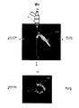
図5は、本実施例の燃料噴射弁1が噴射する噴霧を撮影した実験結果の一例である。実験条件は、大気圧下、燃料圧力は7Mpa程度である。縦断面の噴霧撮影は、レーザのシート光が弁体軸線Jを含む平面となるように設定して、噴霧に照射し、燃料噴射後約2〜3msの噴霧の映像をカメラにて撮影した。同様に、噴霧横断面は、レーザのシート光が弁体軸線に垂直なX−X面となるように設定して撮影した。図に示すように、本実施例の燃料噴射弁1から噴射される噴霧の縦/横断面は、矢印“PLUG”側に偏向し、偏向側で可燃濃度の混合気が濃く、矢印“PISTON”側で可燃濃度の混合気が希薄とな領域80Aのような分布となる。
【0032】
図6は、本実施例の燃料噴射弁1が噴射した噴霧の流量分布の一例を示す図である。図6の(a)は、流量分布を測定した噴霧断面の一例を示し、(b)は図(a)に定義する線m上の流量分布、(c)は線k上の流量分布を示す。実験条件は、図5と同等である。図(b)、(c)の横軸は、線m及びk上の測定ポイント、縦軸は最大流量を1として無次元化している。図(b)に示すように、噴霧は“PLUG”側に多く分布し、“PISTON”側で少なく分布している。また、図(c)に示すように、線k上の分布はほぼ対称である。
【0033】
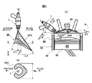
図3(a)に示すように、本実施例の燃料噴射弁1から噴射される噴霧は、矢印“PLUG”側に偏向角βで偏向し、偏向側で可燃濃度の混合気が濃く、矢印“PISTON”側で可燃濃度の混合気が希薄となる。噴射孔8の中心軸線からとった“PLUG”側噴霧角α1と“PISTON”側噴霧角α2とは、α1>α2の関係にあり、領域80のような分布となる。また、矢印“PLUG”側、すなわち噴射孔8の出口を切り欠いた側に噴射される燃料噴霧の到達距離の方が、矢印“PISTON”側、すなわち噴射孔8の出口を切り欠かなかった側に噴射される燃料噴霧の到達距離よりも長くなる。ここで、弁軸線Jを含みJに平行な面内の噴霧の縦断面は、網目状のハッチングをした領域80Aとなる。ここで、偏向角βは、次式で求められる。
【0034】
【数2】
β=(α1−α2)/2
また、図3(b)に示すように、矢印Nの方向から見た噴霧のX−X横断面は、“PLUG”側に可燃濃度の混合気が濃く、矢印“PISTON”側では可燃濃度の混合気が希薄、極端な場合には燃料粒子が存在しない状態になる。すなわち、領域80Aに示すような、矢印“PISTON”側で噴霧の一部が切れたような分布となる。さらに、本実施例の燃料噴射弁1を、内燃機関60に対して、取り付け角γ、矢印“PLUG”と“PISTON”の向きを図3(c)に示す向きに取り付けた場合、混合気は内燃機関60に設けられた点火装置65の周辺に収斂し、一方、シリンダ68内に往復可能に取り付けたピストン69のキャビティ69Aの周辺では希薄となり、噴霧上端角αu、領域80のような分布となる。すなわち、噴霧角は点火装置65側に大きく、ピストン69のキャビティ69A側に小さく、また可燃混合気の濃度は点火装置65側に濃く、ピストン69のキャビティ69A側に薄く、また到達距離は点火装置65側で長く、ピストン69のキャビティ69A側で短くなっている。ここで、噴霧上端角αuは、矢印θ方向を正とする。図3(c)においては、燃焼室内67には噴霧以外の気体の流動は無く筒内圧力は大気圧にほぼ等しいものとする。
【0035】
図4の断面A−Aから、B−Bまでの区間(区間A−B)と、断面B−Bから、C−Cまでの区間(区間B−C)とでの、燃料の開放部分と噴霧噴射状態の比較について説明する。A−B間では、噴射孔8全周で燃料を拘束しているため、噴霧は噴射されない。一方、B−C間では、燃料は、図示するように半円状に開放されており、噴霧は“PLUG”側に噴射され、“PISTON”側には噴射されず、図に示すように噴霧の一部が切れた、馬蹄形状の断面形状となる。従って、噴霧は、ピストン69の運動によって燃焼室内67の圧力が変化しても、噴霧内部と噴霧外部の圧力がバランスし易く、噴霧が潰れにくく、形状が一定に保たれる。
【0036】
本実施例では、段差(L'−L)はシリンダの内径、すなわちエンジンの容積と噴射弁の取付角によって適宜決められるものであるが、少なくとも0よりも大きな段差で設けられ、実質的な噴霧構造(広がり角度、到達距離、空間的分布)の変化を得るためには、エンジンの容積が2〜3リットル、噴射弁の取付角が10°〜50°の通常の範囲において、(L'−L)は、0<(L'−L)/d0≦1の範囲に設定されることが好ましい。
【0037】
本実施例では、ノズル部材7の先端面の噴射孔8の出口部に突起部7Aを形成しているが、この突起部7Aは必ずしも設ける必要はなく、突起部7Aを設けない構造においては切り欠かれていない(最も切り欠きの少ない)部分の噴射孔長さはL″になる。このとき、噴射孔長さの大小関係はL′>L″>Lのようになる。しかし、突起部7Aを設けることにより、突起部7Aのみの重量増によって、大きな段差(L'−L)を構成し、より大きな噴霧角α1(図3の(a))を実現することができる。
【0038】
さらに、噴射孔幅Wを調節することで、噴霧断面の広がりWs((図3の(b))を調整することができ、Wを小さくすることでWsを小さくし、Wを大きくすることでWsを大きくすることができ、Wは0<W≦d0の範囲で設定することができる。
【0039】
上述のように、段差(L'−L)の大きさを調節することにより、噴霧の偏向量(図3(a)に示す角度α1又はβ)を調節することができる。さらに、クリアランスC1を調整することによっても噴霧の偏向量を調整でき、例えば、C1を小さくすることで偏向量を多くすると良い。また、噴射孔8の通路壁を取り除く範囲(通路壁を短くする範囲)を噴射孔8の周方向において調節することによって、噴霧の横断面の広がりWsを調節することができる。
【0040】
ノズル部突起部7Aは、図7に示すような形状にしてもよい。
【0041】
図7に示す突起部7Cの内側(噴射孔8側)には、クリアランスC1、幅W3の略U字型の切り欠き部が形成されている。噴霧の横断面の広がりWsは、突起状壁の寸法W3で調節すると良い。突起部7Cをエンドミル等で削り出す場合には、例えばW3=d0+2・C1であると加工が容易となる。
【0042】
さらに、ノズル部突起部7Aは、図8に示す、長さW4、幅W5で規定される切り欠き部を有する突起部7Dで形成してもよい。この場合、W4、W5を用いて噴霧形状を微調整すると良い。“PLUG”側に分布する噴霧を多くするには、例えばW4=d0/2に設定すると良い。また、“PLUG”側に分布する噴霧を少なくするにには、例えば、W4<d0/2の範囲ではW4を小さく、W4>d0の範囲ではW4を大きくすると良い。また、W5は、0<W5≦d0+2・C1の範囲で設定されることが好ましく、“PLUG”側に分布する噴霧を多くするためには、例えば、W5=d0+2・C1に設定するとよい。
【0043】
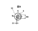
さらに、ノズル部突起部7Aは、図9に示すクリアランスC1、幅W6の略環状の切り欠き部(凹部)を有する突起部7Eで形成してもよい。この場合、ボール6がシート面9に着座する際の振動騒音を低減することができる。
【0044】
ここで、図9について、さらに検討する。この実施形態では、突起部7Eの内周壁によって、噴射孔8の出口開口の周囲に、壁面(周壁)が形成されている。この壁面と噴射孔8の出口開口縁との間には、弁体40の駆動方向(弁軸心方向)を横切る方向に間隔(スペース)が設けられ(すなわち、壁面と出口開口縁とが弁軸心方向を横切る方向にずれている)、この間隔の大きさが噴射孔8の出口開口の周方向で変化している。図2の構成では、この間隔の大きさが、噴射孔8の周方向の略180度の範囲で、クリアランスC1に形成され、残る180度の範囲で、クリアランスC1から実質的に無限大に変化しているものと考えることができる。ここで、実質的に無限大である状態とは、噴射孔8を取り囲む壁面(周壁)が、噴射される燃料に対して、拘束力を作用しない状態を意味する。別の見方をすれば、噴射孔8の出口開口の周方向の一部分に、突起部7Aによる壁面が設けられていることになる。また図7及び図8では、周壁の開放部分(W3及びW8の幅を有する切り欠き部分)が、図2の構成よりもさらに狭くなった一実施形態と考えることができる。また、図9の形態例は、周壁と噴射孔8の出口開口縁との間隔の大きさがクリアランスC1から徐々に増加し、最も大きくなる部分では、実質的に無限大になっている例である。すなわち、噴射される燃料噴霧に対する拘束力が、クリアランスC1部分で最も大きく、この部分から噴射孔8の出口開口の周方向に徐々に小さくなり、前述の間隔が最も大きくなる部分では、実質的にゼロになるようにしている。また、クリアランスC1の大きさは、場合によっては0にしても良い。すなわち、周壁と噴射孔8の内周面とが弁軸心を横切る方向にずれることなく一致するように形成される場合もあり得る。
【0045】
ノズル部材7部は、図10に示すような構成にしてもよい。
【0046】
図10(a)、(b)に示すノズル部材7′では、その底面部(端面部)71の外周部に肉厚部7Fを設けている。すなわち、本構成においては、肉厚部7Fによって、ボール6がシート面9に着座する際の振動騒音を低減している。
【0047】
また、図10(c)、(d)に示すように噴射孔8中心から距離B1で、厚さ(B2−B1)の略環状の肉圧部7Gによって、振動騒音低減をしても良い。
【0048】
さらに、ノズル部材7′′′部は、図11に示すような構成にしてもよい。
【0049】
ノズル部材7′′′部は、燃料旋回素子及び弁体の一部を収納するハウジングの底面部71′のみによって構成され、側壁部72′とは別部材で構成されている。側壁部72′は、ノズル部材7′′′をガイドするノズルガイド体を構成する。ノズル部材7′′′は接合部7Hに沿って側壁部72′(ノズルガイド体)に溶接されている。すなわち、本構成においては、エンジンの容積と噴射弁の取付角によって適宜変更する部分を、ハウジングの底面部71′のみに集約することで、生産性を向上できる。
【0050】
図12を用いて、内燃機関の実施例を説明する。
【0051】
シリンダ68内に往復動可能に設けられたピストン69は、図示しないクランクシャフトの回転に応じてシリンダ68内を上下動する。シリンダ68の上部には、シリンダヘッド63が取り付けられており、シリンダ68と共に密閉空間を形成する。シリンダヘッド63には、スロットルバルブを内蔵した吸入空気量制御装置61を介して外部空気をシリンダ内に導く吸気マニホールド62と、シリンダ68内で燃焼した燃焼ガスを排気装置へ導く排気マニホールドとが形成されている。
【0052】
シリンダヘッド63の吸気マニホ−ルド62側には吸気弁64が、中央部には点火装置65が、そして吸気弁64と反対側には排気弁66がそれぞれ設けられている。吸気弁64および排気弁66は燃焼室67内に延在して設けられている。ここで、燃料噴射弁1は、シリンダヘッド63の吸気マニホ−ルド62結合部付近に取り付けられており、燃料噴射弁1の軸線が燃焼室67内でやや下向きとなるように(点火装置65が設けられているのとは反対方向を向くように)設定されている。その取り付け角度γは一般に10°〜50°程度である。69はピストンを示しており、69Aはピストン69に設けられたキャビティ(凹み)である。キャビティ69Aは、ピストン69の径方向において、排気弁66側から、点火装置65の取り付け位置を越えて吸気弁64側(ほぼ噴射孔8の位置)までの範囲に設けられている。噴射孔8はピストン69に設けられるキャビティ69Aに向けられている。図中の白抜きの矢印は吸気の流れを示しており、ハッチングの矢印は排気の流れをそれぞれ示している。内燃機関60の燃料は、吸気のタイミングに合わせて燃料噴射弁1により直接燃焼室67内へ噴射され、着火の直前には領域80のように分布する。噴射により霧化した燃料は、燃焼室67において吸気マニホールド62を経て導かれた空気の流れ(タンブル流)82との混合を促進する。タンブル流は、シリンダヘッド側を排気弁66側に流れ、排気弁66の下方でピストン側に向きを変え、キャビティ69Aの曲面に沿って燃料噴射弁8側に導かれ、噴霧を下側から持ち上げるように流れる。点火装置65側に偏向している噴霧は、タンブル流82によって、さらに点火装置65に向かうようになる。また一方、キャビティ69Aの方向に向かう噴霧は、希薄となりピストン69側に燃料噴霧を過剰に送ることがない。従って、燃料噴霧のピストンへの付着を低減できる。しかる後の混合気は、圧縮行程中に圧縮され、点火装置65にて安定して着火され、未然ガスの排出量が抑制された安定した燃焼が実現される。噴霧の一部を切ることで、噴霧の内側と外側とで圧力差がなくなり、筒内の圧力変動に対して噴霧形状が変化し難く、広いエンジン回転数域で燃焼安定性の良い噴霧を提供できる。
【0053】
上記の筒内噴射ガソリンエンジンは、燃焼室内にタンブル流を生成するもので、従来エンジンのシリンダヘッドを大幅に変更することなく希薄燃焼を実現することができる。
【0054】
上記の各実施例の燃料噴射弁によれば、噴射孔の出口部で噴射孔を形成する壁面の一部を取り除くことにより、噴霧の流れの拘束を解き、拘束を解いた側で可燃濃度の混合気が濃く、拘束した側で可燃濃度の混合気が希薄な偏向噴霧を形成する。このため、噴射孔の一部を遮蔽する場合のように噴霧の流れを阻害しにくい。これは、燃料に旋回力を付与して噴射する燃料噴射弁の場合に、付与した旋回エネルギーを損なうことが無く、特に有効である。
【0055】
また、上記の各実施例の燃料噴射弁は、噴射孔の出口部で噴射孔を形成する壁面の一部を切り欠いて、或いは、噴射孔の噴射孔長さが噴射孔の周方向で変化するように、噴射孔の出口開口部に段差を設けて、或いは、噴射孔を形成する壁面の一部を含むノズル先端面に凹部を形成して実施することができる。これらの実施例は見方を変えれば、噴射孔を形成する壁面の一部を他の部分よりも下流側(ノズル体の先端側)に延長して設けることになる。
【0056】
内燃機関の他の実施例を、図13を用いて説明する。
【0057】
図13に示す内燃機関60′では、タンブル流82を点火装置65直下から立ち上げるように、キャビティ69Bを設けている。キャビティ69Bは、ピストン69′の径方向において、点火装置65の取り付け位置(シリンダ中心部)よりも排気弁66側からほぼ点火装置65の取り付け位置までの範囲に設けられている。タンブル流82は、シリンダヘッド側を排気弁66側に流れ、排気弁66の下方でピストン側に向きを変え、キャビティ69Aの曲面に沿って流れ、点火装置65直下から噴霧を持ち上げるように、点火装置65に向かう流れを作る。キャビティ69Bが誘導するタンブル流82によって、可燃濃度の混合気80の点火装置65への収斂性を高めることが可能である。
【0058】
キャビティの形状は、図13(b)の破線69Cに示すような略楕円状であってもよい。
【0059】
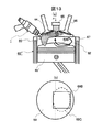
内燃機関の他の実施例を、図14を用いて説明する。
【0060】
図14に示す内燃機関60′′では、キャビティの無い、フラットピストン69を設けている。図2及び3で説明した、L、L'、L''、do、Wを調整することによって適切な噴霧角α1、α2、β及びαu、噴霧広がりWsを設定し、タンブル流を用いずに、あるいは、比較的弱いタンブル流で、可燃濃度の混合気80を点火装置65に到達させることが可能である。
【0061】
次に、図15を参照して、燃料噴射弁の他の実施例を説明する。
図15に示すノズル部材7部では、噴射孔8の出口部に噴霧の一部を遮蔽する部材73を設けている。上流側(図15中で部材73より上方)の噴霧がいかなる形状であっても、部材73によって強制的に噴霧の一部を切ることが可能である。従って、ノズル設計裕度の広がりが期待できる。部材72は必ずしも別体でなくて良い。
【0062】
さらに、図16に示すように、噴射孔8内部の一部に、突起部7Iを設けることで、燃料の一部を遮断して噴霧の一部を切っても良い。突起部7Iは、プレス加工等の塑性加工を用いると良い。
【0063】
内燃機関の他の実施例を、図17を用いて説明する。
【0064】
図17に示す内燃機関60′′′では、図12で説明した実施例とは逆回転のタンブル流83をガイドするキャビティ69Cを設けている。本実施例が上記実施例と異なる点は、タンブル流83がキャビティに案内されて上昇して点火装置65に向かう際に、混合気80と対抗するために、混合気80の排気バルブ66方向への進行が抑制され、シリンダ68壁面への燃料付着を抑制することが可能である。また、タンブル流83が混合気80とキャビティ69Cの間を通過するために、ピストン側への燃料付着を抑制するのにも有効である。
【0065】
【発明の効果】
本発明によれば、噴射孔の出口部で、この出口開口の周方向の一部で噴霧の流れが拘束されず開放されるため、この方向へ混合気が収斂し、また反対方向への噴霧はその流れが拘束されるため燃料粒子が希薄になり、噴霧内外の圧力差を小さくして噴霧を潰れにくくした、偏向噴霧を形成できる。
【0066】
さらに、内燃機関において、点火装置方向へ混合気を収斂し、ピストン方向への燃料粒子を希薄にするように噴霧を形成することによって、内燃機関の点火性を良好とし、燃焼の未燃ガス成分の排出量を低減できる。
【図面の簡単な説明】
【図1】本発明の一実施例である電磁式燃料噴射弁の縦断面図である。
【図2】電磁式燃料噴射弁1のノズル部材7の拡大図を示しており、(a)はノズル部材7部の縦断面図、(b)は(a)のノズル部材7部を矢印N方向から見た平面図を示している。
【図3】(a)は、本発明に係る燃料噴射弁が、燃料を大気中に噴射する場合の噴霧、(b)は(a)の断面X−Xにおける噴霧を矢印Nから見た横断面図、(c)は燃料を直接、燃焼室(シリンダ)内に噴射する内燃機関に適用した様子を模式的に示した図である。
【図4】本発明に係る燃料噴射弁の噴射孔部の拡大図と、燃料開放部分の形状及び噴霧断面構造を模式的に示したものである。
【図5】(a)は、本発明に係る燃料噴射弁が、燃料を大気中に噴射する場合の噴霧縦断面の写真、(b)は(a)の断面X−Xにおける噴霧を矢印Nから見た横断面図写真である。
【図6】(a)は、本発明に係る燃料噴射弁が、燃料を大気中に噴射する場合の噴霧横断面の写真、(b)(c)は(a)に定義する線上の流量分布を示すグラフである。
【図7】本発明に係る他の実施例における、ノズル部材7の突起部7Cの拡大図を示している。
【図8】本発明に係る他の実施例における、ノズル部材7の突起部7Dの拡大図を示している。
【図9】本発明に係る他の実施例における、ノズル部材7の突起部7Eの拡大図を示している。
【図10】本発明に係る他の実施例における、ノズル部材7の拡大図を示しており、(a)、(c)はノズル部材7の縦断面図、(b)は(a)の、(d)は(c)のノズル部材7を矢印N方向から見た平面図を示している。
【図11】本発明に係る他の実施例における、ノズル部材7の拡大図を示しており、(a)はノズル部材7部の縦断面図、(b)は(a)のノズル部材7部を矢印N方向から見た平面図を示している。
【図12】本発明に係る内燃機関の実施例を示しており、(a)は縦断面図、(b)は燃焼室を図(a)の矢印P側から見た模式図、(c)はピストンヘッドを矢印Pから見た模式図である。
【図13】本発明に係る内燃機関の他の実施例を示しており、(a)は内燃機関の縦断面図、(b)はピストンヘッドを矢印Pから見た模式図である。
【図14】本発明に係る内燃機関の他の実施例を示す縦断面図である。
【図15】本発明に係る燃料噴射弁の他の実施例における、ノズル部材7部の拡大図を示しており、(a)は縦断面図、(b)は(a)の矢印N方向から見た平面図である。
【図16】図12に係る他の実施例を示す図であり、噴射孔の先端部と噴射孔の出口側から見た平面図を示している。
【図17】本発明に係る内燃機関の他の実施例を示す模式図である。
【符号の説明】
1…電磁式燃料噴射弁、40…弁体、6…ボ−ル弁、8…噴射孔、7…ノズル、7A…ノズル突起部、A1…L型切り欠き面、80…偏向噴霧の分布形状、、22…燃料旋回素子、23…案内孔、32…軸方向燃料通路、33…燃料旋回室、60…内燃機関、69A…ピストンキャビティ、70…電磁式燃料噴射弁。[0001]
BACKGROUND OF THE INVENTION
The present invention relates to a fuel injection valve that injects fuel into an internal combustion engine, and relates to a technique for forming a fuel spray excellent in ignitability and combustibility.
[0002]
[Prior art]
An in-cylinder fuel injection device that directly injects fuel into a combustion chamber is known as opposed to an intake pipe fuel injection device that injects fuel into an engine intake pipe.
[0003]
As such an in-cylinder injection gasoline engine, there is one described in JP-A-6-146886. In this prior art, consideration is given to the mounting position of the fuel injection valve, and a configuration in which a vertical vortex intake flow (tumble flow) is formed in the combustion chamber by an intake port extending upward from the intake opening end, which is leaner than the theoretical mixture. The fuel is stably burned to improve fuel efficiency.
[0004]
[Problems to be solved by the invention]
In the above prior art, sufficient consideration is not given to the spray shape or spray structure that can improve both ignitability (ignitability) and flammability (reduction of unburned gas emissions) as described below. Was not made.
[0005]
In order to optimize the spray injected from the fuel injection valve, it is necessary to consider the following characteristics. The first is the spray shape, and the spread angle and the reach distance of the spray are factors. The second is the spray particle size, and it is necessary to make the particle size distribution uniform by reducing the number of large particles as much as possible. The third is a spray structure, and it is necessary to optimize the spatial distribution of sprayed fuel particles.
[0006]
As a result of studying how these spray characteristics are related to the combustion characteristics of an internal combustion engine, the following has been clarified. In order to improve ignitability, it is effective to increase the fuel particle distribution around the igniter and increase the distribution of the air-fuel mixture having a combustible concentration. On the other hand, when the fuel particle distribution in the piston direction is decreased, the unburned gas components (HC, CO) of combustion tend to decrease, and the combustibility is improved. Furthermore, in order to obtain combustion stability in a wide region from low engine speed to high engine speed, it is desirable that the spray shape does not change due to the pressure change in the cylinder. This is because, since the geometric positional relationship between the injector and the ignition device is fixed, it is important that the spray spread is constant in order to always supply an appropriate concentration of spray to the ignition device. . In other words, the spray injected by the conventional injector has a tendency that the spray spreads when the in-cylinder pressure is low, and the spray is crushed when the in-cylinder pressure increases. In this case, if the arrangement of the injector and the ignition device is determined based on the state where the in-cylinder pressure is relatively high, when the in-cylinder pressure is low, the fuel easily adheres to the cylinder upper surface and side surfaces or the piston head. On the other hand, when the in-cylinder pressure is relatively low as a reference, when the in-cylinder pressure becomes high, there is a tendency that spray suitable for combustion does not easily reach the ignition device.
[0007]
An object of the present invention is to realize a spray suitable for improving the ignitability of an internal combustion engine and reducing the emission amount of unburned gas components of combustion.
[0008]
[Means for Solving the Problems]
In order to achieve the above object, a spray that does not easily change its shape with respect to the pressure change in the cylinder is generated. For this purpose, the air-fuel mixture is converged in the direction of the igniter, and a spray is formed in which the fuel particles in the direction of the piston are diluted. At this time, the air outside the spray can be attracted into the spray from the portion where the fuel particles are diluted (in some cases, the fuel molecules are lost). Thereby, the pressure difference between the inside and outside of the spray can be reduced, and the spray is hardly crushed.
[0009]
Specifically, by removing a part of the wall surface that forms the injection hole at the outlet portion of the injection hole that is provided in the fuel injection valve and injects the fuel, the restriction on the flow of the spray is released. It is desirable to form a deflected spray that is thick and thin on the constrained side. At this time, it is desirable to change the restraining force nonlinearly.
[0010]
In an internal combustion engine, the fuel injection valve may be arranged so that a thick spray is formed on the ignition device side and a thin spray is formed on the piston side.
[0011]
DETAILED DESCRIPTION OF THE INVENTION
An embodiment of the present invention will be described with reference to FIGS. In the following description, a plane including the valve axis (valve axis) and parallel to the valve axis is referred to as a longitudinal section, and a plane perpendicular to the valve axis is referred to as a transverse section.
[0012]
The electromagnetic
[0013]
The yoke 3 is provided with a
[0014]
Further, the stroke of the valve body 40 (the amount of movement upward in FIG. 1) is set by the size of the gap between the receiving surface 5C of the neck portion of the
[0015]
Next, the
[0016]
The center of the
[0017]
According to the said structure, the exit opening surface of the
[0018]
It is desirable that the above-described notch changes the spray restraint force nonlinearly in the circumferential direction of the
[0019]
(1) The two intersections of the cross section including the central axis of the
(2) At this time, between the two intersections and the stepped portion, the two edges forming the outlet opening are parallel to each other when viewed from the direction perpendicular to the cross section.
(3) Further, the edge forming the outlet opening is a stepped portion and is formed to change in a direction along the central axis.
(4) The outlet opening surface of the
(5) A step is provided at the outlet opening of the
(6) The exit opening of the
(7) A step is formed on the outlet opening surface by forming a step on the nozzle tip surface where the outlet opening of the
(8) A step in the direction of the central axis of the
[0020]
In the configuration of FIG. 2A, the spray has the following characteristics.
[0021]
(A) On the notched side of the passage wall forming the
(B) Since the spray sprayed from the notched side has a large kinetic energy, the spray particle size becomes small.
[0022]
Due to the above effects (a) and (b), the ignitability is improved and the fuel efficiency is improved.
[0023]
In this configuration, since there is a clearance between the edge of the
[0024]
In the above structure, the “notch” in the notch surface A1 or the like does not limit the processing method but means a shape in which a part is removed. A processing method such as press working (plastic working) using a mold material or casting may be used. Further, the
[0025]
In FIG. 2B, the diameter do of the injection hole, the sheet angle θ, the arrow “PLUG”, the arrow “PISTON”, and the lines K and M are defined. The line K is a line passing through the center of the
[0026]
In FIG. 2, the
[0027]
[Expression 1]
S = (angular momentum) / ((momentum in injection axis direction) × (injection hole radius))
= (2 · do · Ls) / (n · ds 2 · cos (θ / 2))
here,
do: Diameter of injection hole Ls: Eccentricity of groove (distance between valve shaft center and groove (width) center)
n: number of grooves θ: angle of valve seat ds: expressed by rheological equivalent diameter using groove width W and groove height H = 2 · W · H / W + H
It is. When this swirl number is increased, atomization is promoted and the spray is dispersed.
[0028]
Operation | movement of the
[0029]
The fuel flows into the
[0030]
Next, the spray structure obtained by the
[0031]
FIG. 5 is an example of an experimental result obtained by photographing the spray injected by the
[0032]
FIG. 6 is a diagram showing an example of the flow distribution of the spray injected by the
[0033]
As shown in FIG. 3 (a), the spray injected from the
[0034]
[Expression 2]
β = (α1-α2) / 2
Further, as shown in FIG. 3 (b), the XX cross section of the spray viewed from the direction of the arrow N shows that the mixture of flammable concentration is dense on the “PLUG” side, and the flammable concentration on the arrow “PISTON” side. When the air-fuel mixture is lean and extreme, fuel particles are not present. That is, the distribution is such that part of the spray is cut off on the arrow “PISTON” side as shown in the
[0035]
The open portion of the fuel in the section from section AA to BB (section AB) and the section from section BB to CC (section BC) in FIG. The comparison of the spray injection state will be described. Between A and B, since the fuel is restrained on the entire circumference of the
[0036]
In this embodiment, the level difference (L′−L) is appropriately determined depending on the cylinder inner diameter, that is, the volume of the engine and the mounting angle of the injection valve. In order to obtain changes in the structure (spreading angle, reach distance, spatial distribution), the engine volume is 2 to 3 liters and the mounting angle of the injection valve is 10 ° to 50 ° in a normal range (L′− L) is preferably set in a range of 0 <(L′−L) / d0 ≦ 1.
[0037]
In this embodiment, the
[0038]
Furthermore, by adjusting the injection hole width W, the spread Ws ((b) of FIG. 3) of the spray cross section can be adjusted, and by reducing W, Ws is reduced and W is increased. Ws can be increased, and W can be set in a range of 0 <W ≦ d0.
[0039]
As described above, the amount of spray deflection (angle α1 or β shown in FIG. 3A) can be adjusted by adjusting the size of the step (L′−L). Further, the amount of deflection of the spray can be adjusted by adjusting the clearance C1, and for example, the amount of deflection can be increased by reducing C1. Further, by adjusting the range in which the passage wall of the
[0040]
The
[0041]
A substantially U-shaped notch having a clearance C1 and a width W3 is formed on the inner side (on the
[0042]
Further, the
[0043]
Furthermore, the
[0044]
Here, FIG. 9 will be further examined. In this embodiment, a wall surface (peripheral wall) is formed around the outlet opening of the
[0045]
The
[0046]
In the
[0047]
Further, as shown in FIGS. 10C and 10D, vibration noise may be reduced by a substantially
[0048]
Further, the
[0049]
The
[0050]
An embodiment of the internal combustion engine will be described with reference to FIG.
[0051]
A
[0052]
An
[0053]
The in-cylinder injection gasoline engine generates a tumble flow in the combustion chamber, and can realize lean combustion without significantly changing the cylinder head of the conventional engine.
[0054]
According to the fuel injection valve of each of the above embodiments, by removing a part of the wall surface that forms the injection hole at the outlet portion of the injection hole, the restriction of the flow of the spray is released, and the combustible concentration is reduced on the side of the release of the restriction. The air-fuel mixture is thick, and a deflected spray with a lean combustible air-fuel mixture is formed on the restricted side. For this reason, it is hard to inhibit the flow of spray like the case where a part of injection hole is shielded. This is particularly effective in the case of a fuel injection valve that injects fuel by applying a turning force to the fuel without impairing the applied turning energy.
[0055]
In the fuel injection valve of each of the above embodiments, a part of the wall surface forming the injection hole is cut out at the outlet of the injection hole, or the injection hole length of the injection hole changes in the circumferential direction of the injection hole. As described above, it can be carried out by providing a step at the outlet opening of the injection hole or by forming a recess on the nozzle tip surface including a part of the wall surface forming the injection hole. From a different perspective, these embodiments are provided by extending a part of the wall surface forming the injection hole to the downstream side (the tip side of the nozzle body) from the other part.
[0056]
Another embodiment of the internal combustion engine will be described with reference to FIG.
[0057]
In the
[0058]
The shape of the cavity may be a substantially elliptical shape as indicated by a
[0059]
Another embodiment of the internal combustion engine will be described with reference to FIG.
[0060]
In the
[0061]
Next, another embodiment of the fuel injection valve will be described with reference to FIG.
In the
[0062]
Furthermore, as shown in FIG. 16, by providing a
[0063]
Another embodiment of the internal combustion engine will be described with reference to FIG.
[0064]
The internal combustion engine 60 '''shown in FIG. 17 is provided with a
[0065]
【The invention's effect】
According to the present invention, at the outlet portion of the injection hole, the flow of the spray is released without being restricted in a part of the circumferential direction of the outlet opening, so that the air-fuel mixture converges in this direction and the spray in the opposite direction. Since the flow is restricted, the fuel particles become dilute, and it is possible to form a deflected spray that makes the spray difficult to collapse by reducing the pressure difference between the inside and outside of the spray.
[0066]
Furthermore, in the internal combustion engine, the air-fuel mixture is converged in the direction of the ignition device, and the spray is formed so as to dilute the fuel particles in the direction of the piston. Emissions can be reduced.
[Brief description of the drawings]
FIG. 1 is a longitudinal sectional view of an electromagnetic fuel injection valve that is an embodiment of the present invention.
2A and 2B are enlarged views of a
3A is a spray when the fuel injection valve according to the present invention injects fuel into the atmosphere, and FIG. 3B is a cross-section as viewed from the arrow N of the spray in the section XX of FIG. FIG. 5C is a diagram schematically showing a state in which the fuel is applied to an internal combustion engine that directly injects fuel into a combustion chamber (cylinder).
FIG. 4 schematically shows an enlarged view of an injection hole portion of a fuel injection valve according to the present invention, a shape of a fuel release portion, and a spray cross-sectional structure.
FIG. 5A is a photograph of a spray vertical section when the fuel injection valve according to the present invention injects fuel into the atmosphere, and FIG. 5B is a photograph of the spray in the section XX of FIG. It is the cross-sectional view photograph seen from.
6A is a photograph of a spray cross-section when the fuel injection valve according to the present invention injects fuel into the atmosphere, and FIGS. 6B and 6C are flow rate distributions on a line defined in FIG. It is a graph which shows.
FIG. 7 shows an enlarged view of a
FIG. 8 shows an enlarged view of a protrusion 7D of a
FIG. 9 shows an enlarged view of a
FIGS. 10A and 10B show enlarged views of the
11A and 11B are enlarged views of the
12A and 12B show an embodiment of an internal combustion engine according to the present invention, in which FIG. 12A is a longitudinal sectional view, FIG. 12B is a schematic view of a combustion chamber viewed from the arrow P side in FIG. FIG. 3 is a schematic view of a piston head viewed from an arrow P.
FIG. 13 shows another embodiment of the internal combustion engine according to the present invention, wherein (a) is a longitudinal sectional view of the internal combustion engine, and (b) is a schematic view of the piston head viewed from an arrow P.
FIG. 14 is a longitudinal sectional view showing another embodiment of the internal combustion engine according to the present invention.
FIGS. 15A and 15B are enlarged views of a
FIG. 16 is a view showing another embodiment according to FIG. 12, and shows a plan view seen from the tip end portion of the injection hole and the outlet side of the injection hole.
FIG. 17 is a schematic view showing another embodiment of the internal combustion engine according to the present invention.
[Explanation of symbols]
DESCRIPTION OF
Claims (4)
前記出口開口の下流側に前記出口開口の縁に沿って前記出口開口の周方向の少なくとも一部を囲む周壁を設け、
前記周壁の内周面と前記出口開口の縁との間に前記出口開口の径方向の隙間を設け、
前記出口開口の周方向における前記周壁の一部に開放部を設け、
前記出口開口から噴射される燃料の流れを前記周壁によって前記出口開口の径方向から拘束すると共に前記開放部において前記拘束を解くことにより、前記噴射孔の中心軸線を中心とする周方向において、前記周壁の設けられた側が前記開放部側と比べて、到達距離が短くかつ希薄な噴霧を形成することを特徴とする燃料噴射弁。An injection hole having an outlet opening formed in the tip surface of the nozzle, a valve seat upstream of the injection hole, a valve body for opening and closing the fuel passage between the valve seat, and driving the valve body In a fuel injection valve comprising drive means and means for imparting a turning force to the fuel upstream of the valve seat ,
Wherein downstream of the outlet opening along the edge of the outlet opening provided with a peripheral wall surrounding at least part of the circumferential direction of the outlet opening,
A gap in the radial direction of the outlet opening is provided between the inner peripheral surface of the peripheral wall and the edge of the outlet opening.
An opening is provided in a part of the peripheral wall in the circumferential direction of the outlet opening ,
By restricting the flow of fuel injected from the outlet opening from the radial direction of the outlet opening by the peripheral wall and releasing the restriction at the opening portion, in the circumferential direction around the central axis of the injection hole, A fuel injection valve characterized in that the side on which the peripheral wall is provided forms a spray with a short reach and a leaner than the open part side .
前記燃料噴射弁として、請求項1乃至3のいずれかに1項に記載された燃料噴射弁を備え、前記燃料噴射弁を前記周壁の開放部が前記点火装置側に向くように配置したことを特徴とする内燃機関。A cylinder, a piston that reciprocates in the cylinder, an intake means for introducing air into the cylinder, an exhaust means for exhausting combustion gas from the cylinder, and a fuel injection that directly injects fuel into the cylinder A fuel supply means for supplying fuel from a fuel tank to the fuel injection valve, an air-fuel mixture of air introduced into the cylinder by the intake means and fuel injected into the cylinder by the fuel injection valve In an internal combustion engine provided with an ignition device for igniting,
The fuel injection valve according to any one of claims 1 to 3 is provided as the fuel injection valve, and the fuel injection valve is disposed so that an opening portion of the peripheral wall faces the ignition device side. A characteristic internal combustion engine.
Priority Applications (1)
| Application Number | Priority Date | Filing Date | Title |
|---|---|---|---|
| JP2000067131A JP4055321B2 (en) | 2000-03-07 | 2000-03-07 | Fuel injection valve and internal combustion engine equipped with the same |
Applications Claiming Priority (1)
| Application Number | Priority Date | Filing Date | Title |
|---|---|---|---|
| JP2000067131A JP4055321B2 (en) | 2000-03-07 | 2000-03-07 | Fuel injection valve and internal combustion engine equipped with the same |
Publications (3)
| Publication Number | Publication Date |
|---|---|
| JP2001248525A JP2001248525A (en) | 2001-09-14 |
| JP2001248525A5 JP2001248525A5 (en) | 2006-03-23 |
| JP4055321B2 true JP4055321B2 (en) | 2008-03-05 |
Family
ID=18586371
Family Applications (1)
| Application Number | Title | Priority Date | Filing Date |
|---|---|---|---|
| JP2000067131A Expired - Fee Related JP4055321B2 (en) | 2000-03-07 | 2000-03-07 | Fuel injection valve and internal combustion engine equipped with the same |
Country Status (1)
| Country | Link |
|---|---|
| JP (1) | JP4055321B2 (en) |
Families Citing this family (3)
| Publication number | Priority date | Publication date | Assignee | Title |
|---|---|---|---|---|
| JP4508142B2 (en) * | 2005-05-24 | 2010-07-21 | 株式会社デンソー | Fuel injection valve for internal combustion engine |
| JP6436134B2 (en) * | 2016-07-05 | 2018-12-12 | トヨタ自動車株式会社 | Control device for internal combustion engine |
| CN117919977B (en) * | 2024-03-20 | 2024-07-05 | 山西众智科技有限责任公司 | Gas mixing device |
-
2000
- 2000-03-07 JP JP2000067131A patent/JP4055321B2/en not_active Expired - Fee Related
Also Published As
| Publication number | Publication date |
|---|---|
| JP2001248525A (en) | 2001-09-14 |
Similar Documents
| Publication | Publication Date | Title |
|---|---|---|
| JP4055315B2 (en) | Fuel injection valve and internal combustion engine equipped with the same | |
| JP3651338B2 (en) | In-cylinder fuel injection valve and internal combustion engine equipped with the same | |
| US7344090B2 (en) | Asymmetric fluidic flow controller orifice disc for fuel injector | |
| JP3771361B2 (en) | Fuel injection valve | |
| JPH0378562A (en) | Fuel injection valve | |
| JP4055321B2 (en) | Fuel injection valve and internal combustion engine equipped with the same | |
| JP2003148299A (en) | Fuel injection valve and internal combustion engine loaded with the same | |
| JP4043966B2 (en) | Fuel injection valve | |
| JP2004332657A (en) | Fuel injection valve | |
| JP2002206469A (en) | Fuel injection valve and internal combustion engine loaded with the same | |
| JP2008014321A (en) | Fuel injection valve and internal combustion engine having it | |
| JPH11336643A (en) | Electromagnetic fuel injection valve for cylinder injection | |
| JP2002130084A (en) | Fuel injection valve and internal combustion engine mounted therewith | |
| JP2000097030A (en) | Direct injection type internal-combustion engine and fuel injection valve for direct injection | |
| JP2007224929A (en) | Fuel injection valve | |
| JP2000274328A (en) | Fuel injection valve for cylinder injection | |
| JP3991053B2 (en) | Fuel injection valve | |
| JP2001123915A (en) | Cylinder fuel injection valve and internal combustion engine therewith | |
| JPH10318096A (en) | Fuel injection valve and internal composition engine equipped with the same | |
| JP2000303935A (en) | In-cylinder fuel injection device | |
| JP2000314354A (en) | Cylinder fuel injection device | |
| JP2001123910A (en) | Fuel injection valve for cylinder injection | |
| JP2000230469A (en) | Cylinder fuel injection device | |
| JP2008019870A (en) | Fuel injection valve | |
| JP2000240536A (en) | Direct fuel injection device |
Legal Events
| Date | Code | Title | Description |
|---|---|---|---|
| A521 | Written amendment |
Free format text: JAPANESE INTERMEDIATE CODE: A523 Effective date: 20060203 |
|
| A621 | Written request for application examination |
Free format text: JAPANESE INTERMEDIATE CODE: A621 Effective date: 20060203 |
|
| RD01 | Notification of change of attorney |
Free format text: JAPANESE INTERMEDIATE CODE: A7421 Effective date: 20060417 |
|
| A131 | Notification of reasons for refusal |
Free format text: JAPANESE INTERMEDIATE CODE: A131 Effective date: 20070828 |
|
| A977 | Report on retrieval |
Free format text: JAPANESE INTERMEDIATE CODE: A971007 Effective date: 20070830 |
|
| A521 | Written amendment |
Free format text: JAPANESE INTERMEDIATE CODE: A523 Effective date: 20071026 |
|
| TRDD | Decision of grant or rejection written | ||
| A01 | Written decision to grant a patent or to grant a registration (utility model) |
Free format text: JAPANESE INTERMEDIATE CODE: A01 Effective date: 20071120 |
|
| A61 | First payment of annual fees (during grant procedure) |
Free format text: JAPANESE INTERMEDIATE CODE: A61 Effective date: 20071203 |
|
| R151 | Written notification of patent or utility model registration |
Ref document number: 4055321 Country of ref document: JP Free format text: JAPANESE INTERMEDIATE CODE: R151 |
|
| FPAY | Renewal fee payment (event date is renewal date of database) |
Free format text: PAYMENT UNTIL: 20101221 Year of fee payment: 3 |
|
| FPAY | Renewal fee payment (event date is renewal date of database) |
Free format text: PAYMENT UNTIL: 20101221 Year of fee payment: 3 |
|
| S111 | Request for change of ownership or part of ownership |
Free format text: JAPANESE INTERMEDIATE CODE: R313111 |
|
| FPAY | Renewal fee payment (event date is renewal date of database) |
Free format text: PAYMENT UNTIL: 20101221 Year of fee payment: 3 |
|
| R350 | Written notification of registration of transfer |
Free format text: JAPANESE INTERMEDIATE CODE: R350 |
|
| FPAY | Renewal fee payment (event date is renewal date of database) |
Free format text: PAYMENT UNTIL: 20101221 Year of fee payment: 3 |
|
| FPAY | Renewal fee payment (event date is renewal date of database) |
Free format text: PAYMENT UNTIL: 20111221 Year of fee payment: 4 |
|
| FPAY | Renewal fee payment (event date is renewal date of database) |
Free format text: PAYMENT UNTIL: 20111221 Year of fee payment: 4 |
|
| FPAY | Renewal fee payment (event date is renewal date of database) |
Free format text: PAYMENT UNTIL: 20121221 Year of fee payment: 5 |
|
| FPAY | Renewal fee payment (event date is renewal date of database) |
Free format text: PAYMENT UNTIL: 20131221 Year of fee payment: 6 |
|
| LAPS | Cancellation because of no payment of annual fees |