JP4054026B2 - Chip removal device for band saw machine - Google Patents
Chip removal device for band saw machine Download PDFInfo
- Publication number
- JP4054026B2 JP4054026B2 JP2005054253A JP2005054253A JP4054026B2 JP 4054026 B2 JP4054026 B2 JP 4054026B2 JP 2005054253 A JP2005054253 A JP 2005054253A JP 2005054253 A JP2005054253 A JP 2005054253A JP 4054026 B2 JP4054026 B2 JP 4054026B2
- Authority
- JP
- Japan
- Prior art keywords
- band saw
- saw blade
- brush
- pair
- shaft
- Prior art date
- Legal status (The legal status is an assumption and is not a legal conclusion. Google has not performed a legal analysis and makes no representation as to the accuracy of the status listed.)
- Active
Links
Images


Description
本発明は帯鋸盤における切粉除去装置に関する。さらに詳細には、横型帯鋸盤、縦型帯鋸盤等の鋸盤において鋸刃が被切断材を切断した際に鋸刃に付着した切粉を除去するための切粉除去装置に関する。 The present invention relates to a chip removing device in a band saw. More particularly, the present invention relates to a chip removing device for removing chips adhering to a saw blade when the saw blade cuts a material to be cut in a saw blade such as a horizontal band saw machine or a vertical band saw machine.
例えば、上述の鋸盤の一つである横型帯鋸盤において切断加工を行うと必ず切粉が発生する。発生した切粉の一部は鋸刃のガレット部分に付着して、駆動ホイールおよび従動ホイールに搬送され、鋸刃とホイール間に入り込み、鋸刃やホイールが損傷したり鋸刃がスリップしたりするため、鋸刃に付着した切粉を除去する必要がある。 For example, chips are always generated when cutting is performed in a horizontal band saw that is one of the above-described saws. Part of the generated chips adheres to the galette part of the saw blade and is transported to the drive wheel and driven wheel, and enters between the saw blade and the wheel. The saw blade and the wheel are damaged or the saw blade slips. Therefore, it is necessary to remove the chips adhering to the saw blade.
鋸刃に付着した切粉を除去するための切粉除去装置としては、従来より種々の装置が考案されているが、横型帯鋸盤における一般的な切粉除去装置の例として、帯鋸刃を走行自在に設けた鋸刃ハウジングに鋸刃に付着した切粉を除去するブラシを回転自在に支持するブラシ支持部材を設け、鋸刃に近接した位置に前記ブラシが当接可能なストッパー部材を設け、前記ブラシ支持部材をストッパー部材に接近、離反する方向へ移動可能に設けると共に、前記ブラシをストッパー部材に当接する方向へ付勢するスプリングによる付勢手段を設け、前記ブラシの毛先に対して鋸刃が所定量だけ入り込んだときに前記ブラシ支持部材を固定する固定手段を設けた構成の切粉除去装置のものがある(例えば特許文献1)。
上述の切粉除去装置においては、ブラシを位置決めするストッパー部材と、ブラシ支持部材を固定する手段であるロックシリンダーを備えた複雑な構成の固定手段とが必要である。また、スプリングによって常時ブラシを鋸刃に押圧付勢しているので、鋸刃交換時にはブラシを交換に支障のない位置へ退避させると共に、その位置に前述の固定手段による固定が必要である。なお、ブラシが一個であるためブラシが当たらない側に切粉の取り残しができるという問題がある。 The above chip removal device requires a stopper member for positioning the brush and a fixing means having a complicated structure including a lock cylinder that is a means for fixing the brush support member. Further, since the brush is always pressed and urged by the spring to the saw blade, when replacing the saw blade, the brush must be retracted to a position where there is no hindrance to the replacement, and the position must be fixed by the fixing means. In addition, since there is one brush, there is a problem that chips can be left on the side where the brush does not hit.
本発明は上述の如き問題を解決するためになされたものであり、本発明の課題は、ブラシを切粉除去位置へ位置決めするストッパー部材が不要であり、かつブラシを退避位置へ保持する固定手段が不要であり、また切粉の取り残しがない切粉除去能力のよい帯鋸盤における切粉除去装置を提供することである。 The present invention has been made in order to solve the above-described problems, and an object of the present invention is to eliminate a stopper member for positioning the brush to the chip removal position and to fix the brush to the retracted position. Is to provide a chip removing device in a band saw machine having a good chip removing capability in which no chips are left behind.
本発明は、前述のごとき問題に鑑みてなされたもので、鋸刃ハウジングに回転自在に支持された駆動ホイール(17)と従動ホイール(21)とに環状の帯鋸刃(23)を掛回して備えた帯鋸盤における切粉除去装置であって、前記帯鋸刃(23)の両側から当該帯鋸刃(23)へ押圧される一対のブラシ(57A,57B)を先端部に備えた一対のブラシ軸(59A,59B)を、前記先端部が前記帯鋸刃(23)に対して接近,離反する方向へ回動可能に設けると共に前記帯鋸刃(23)に接近する方向へ付勢して設け、前記一対のブラシ(57A,57B)の摩耗を検出するために設けたセンサー(71)に対して接近離反する方向へ移動自在かつ上記センサー(71)から離反する方向へ付勢された被検出軸(81)を設け、前記付勢力に抗して前記被検出軸(81)を押圧可能な押圧レバー(93)を前記各ブラシ軸(59A,59B)に備え、前記一対のブラシ(57A,57B)の何れか一方または両方の摩耗が使用限界まで進行した場合に、前記ブラシ軸(59A,59B)の一方又は両方の回動により前記押圧レバー(93)によって前記被検出軸(81)を前記付勢力に抗して前記センサー(71)の検出範囲に移動して、前記ブラシ(57A,57B)の使用限界の摩耗を検出する構成であることを特徴とするものである。 The present invention has been made in view of the above-described problems. An annular band saw blade (23) is wound around a drive wheel (17) and a driven wheel (21) rotatably supported by a saw blade housing. A pair of brush shafts, each having a pair of brushes (57A, 57B) pressed against the band saw blade (23) from both sides of the band saw blade (23) at a tip end thereof. (59A, 59B) are provided so that the tip portion can rotate in a direction approaching and separating from the band saw blade (23) and urged in a direction approaching the band saw blade (23), A detected shaft (movable toward and away from the sensor (71) provided to detect wear of the pair of brushes (57A and 57B) and biased away from the sensor (71) ( 81) The against the force be detected shaft (81) and pressable pressure lever (93) wherein each brush shaft (59A, 59B) provided on, the pair brushes (57A, 57B) either or both of When the wear has progressed to the use limit, the sensor shaft (81) is resisted against the biasing force by the pressing lever (93) by the rotation of one or both of the brush shafts (59A, 59B). (71) It moves to the detection range, It is the structure which detects the abrasion of the use limit of the said brush (57A, 57B), It is characterized by the above-mentioned.
また、前記帯鋸盤における切粉除去装置において、前記一対のブラシ軸(59A,59B)は、前記一対のブラシ(57A,57B)が前記帯鋸刃(23)を押圧するように付勢自在かつ前記一対のブラシ(57A,57B)を前記帯鋸刃(23)から離反した状態に付勢自在に構成してあることを特徴とするものである。 Further, in the chip removing device in the band saw machine, the pair of brush shafts (59A, 59B) can be urged so that the pair of brushes (57A, 57B) press the band saw blade (23) and The pair of brushes (57A, 57B) is configured to be urged to be separated from the band saw blade (23) .
また、前記帯鋸盤における切粉除去装置において、前記ブラシの回転方向は、走行している前記帯鋸刃の刃元側から刃先側方向であることを特徴とするものである。 Further, in the chip removal device in the band saw machine, the rotation direction of the brush is from the blade base side to the blade tip side direction of the traveling band saw blade .
また、前記帯鋸盤における切粉除去装置において、前記一対のブラシ軸(59A,59B)は共通のモータ(33)によって回転される構成であることを特徴とするものである。 Further, in the chip removing device in the band saw machine, the pair of brush shafts (59A, 59B) is configured to be rotated by a common motor (33) .
本発明によれば、一対のブラシを帯鋸刃の両側からほぼ一定の押圧力で挟持させる共に、ブラシの回転を刃元側から刃先側方向へ接触回転させて、前記帯鋸刃のガレット部分に付着した切粉を効果的に除去することができる。また、ブラシを切粉除去位置へ位置決めするストッパー部材が不要であり、かつブラシを退避位置へ保持する固定手段が不要である。 According to the present invention, the pair of brushes are clamped from both sides of the band saw blade with a substantially constant pressing force, and the rotation of the brush is contacted and rotated from the blade base side to the blade tip side to adhere to the galette portion of the band saw blade. The removed chips can be effectively removed. Further, a stopper member for positioning the brush to the chip removal position is unnecessary, and a fixing means for holding the brush at the retracted position is unnecessary.
また、一対のブラシの何れか一方が使用限界まで摩耗した場合、ブラシの直径の減少によりブラシ支持体が帯鋸刃側に接近する方向変化として検出して、ブラシの摩耗を検出することができる。 Further, when any one of the pair of brushes is worn to the use limit, it is possible to detect the wear of the brush by detecting the change in the direction in which the brush support approaches the band saw blade side due to the decrease in the diameter of the brush.
以下、本発明の実施の形態を図面によって説明する。 Embodiments of the present invention will be described below with reference to the drawings.
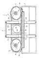
図1を参照するに、鋸盤の一例として、本発明の実施形態に係る切粉除去装置を装備した横型帯鋸盤1が示してある。 Referring to FIG. 1, a horizontal band saw 1 equipped with a chip removing device according to an embodiment of the present invention is shown as an example of a saw.
横型帯鋸盤1は箱状のベースフレーム3を備えており、このベースフレーム3の上面には、紙面の裏面側から被切断材Wを横型帯鋸盤1へ搬入するための被切断材搬入台(図示省略)と、この横型帯鋸盤1で切断された製品を支持する製品受台が設けてある。
The horizontal band saw machine 1 is provided with a box-
前記被切断材搬入台(図示省略)には、被切断材Wを挟持固定自在の固定バイスジョウー5Fと可動バイスジョー5Mとを対向して備えたバイス装置5が設けられている。上記バイス装置5の構成は一般的な構成であって公知であるから、上記バイス装置5の詳細についての説明は省略する。
A
前記ベースフレーム3には左右一対のガイドポスト7L、7Rが立設してあり、このガイドポスト7L、7Rの上端部側は、強度向上、及びガイドポスト7L、7Rの平行度維持を図るべく連結部材9を介して一体的に連結してある。前記左右のガイドポスト7L、7Rには円筒形状のスライドスリーブ11L、11Rが上下動自在に嵌合してあり、この左右のスライドスリーブ11L、11Rのそれぞれ左右外側部には、左右のホイールブラケット13L、13Rがそれぞれ溶接等によって一体的に固定しである。
A pair of left and
上記左右のホイールブラケット13L、13Rは、上部側が後側となるように(図 1 において上部側が裏面側となるように)傾斜してある。そして、前記スライドスリーブ11L、11Rの下部側及び左右のホイールブラケット13L、13Rの下部側は、左右方向に長いビーム部材14と一体的に連結しである。このビーム部材14や左右のホイールブラケット13L、13Rは、後述する駆動ホイール、従動ホイールを回転自在に支持する鋸刃ハウジングを構成するものであり、上側を開口したC型形状に構成してあり、高さ寸法を抑制することができるものである。
The left and
前記ホイールブラケット13Rは、図2に示すように、上部ブラケット13Aと下部ブラケット13Bとを備えた二重構造に構成してあり、上記上下のブラケット13A、13Bに両端側を支持された回転軸15を介して上下のブラケット13A、13Bの間に駆動ホイール17が回転自在に支持されている。なお、上記駆動ホイール17は、前記ホイールブラケット13Rに装着したモータM(図3〜図4参照)によって回転駆動されるものである。
As shown in FIG. 2, the
左側の前記ホイールブラケット13Lには回転軸19を介して従動ホイール21が回転 自在に支持されており、この従動ホイール21と前記駆動ホイール17には環状帯鋸刃23が掛回してある。さらに、前記駆動ホイール17に対して接近離反する方向へ前記従動ホイール21を移動して前記環状帯鋸刃23に張力を付与するための張力付与手段25が前記ホイールブラケット13Lに装着してある。
A driven
上記張力付与手段 25は、前記回転軸19を支持した支持ブロック(図示省略)を前記駆動ホイール17に対して接近離反する方向へ移動することによって帯鋸刃23に張力を付与するもので、例えば油圧シリンダやネジ機構などよりなるものであり、この種の張力付与手段25は公知であるから、張力付与手段25についてより詳細な説明は省略する。
The tension applying means 25 applies tension to the
前記鋸刃ハウジングを上下動するために、例えば油圧シリンダのごとき上下動用アクチュエータ27(図2参照)が設けてあり、この上下動用アクチュエータ27におけるピストンロッド27Pが前記ベースフレーム3の一部に連結しであり、シリンダ本体が前記スライドスリーブ11Rと一体的に連結しである(連結構造の詳細は図示省略)。なお、鋸刃ハウジングを上下動するアクチュエータとしては油圧シリンダに限ることなく、モータによって回転されるボールネジ機構などを採用することも可能である。
In order to move the saw blade housing up and down, for example, a vertical movement actuator 27 (see FIG. 2) such as a hydraulic cylinder is provided, and a
前記駆動ホイール17及び従動ホイール21は、図2に示すように、左右方向の側方から見たとき駆動ホイール17、従動ホイール21の上部側が前記ガイドポスト7L、7Rより後側(図2においては右側)に位置し、前記駆動ホイール17、従動ホイール21の下部側が前記ガイドポスト7L、7Rの前側(図2においては左側)に位置するように前後に傾斜してある。
As shown in FIG. 2, the
そして、側面視において、前記駆動ホイール17、従動ホイール21の軸心Sと両ホイール17、21の幅方向の中心線Lとの交点Oは、側面視において前記ガイドポスト7L、7Rの前後方向の幅にほぼ等しい位置又は前記幅内に位置するように構成しである。
In the side view, the intersection O between the axis S of the
したがって、前記駆動ホイール17と従動ホイール21とに掛回した前記環状帯鋸刃23における直線状の上側走行部23Uは前記一対のガイドポスト7L、7Rの後側に位置し、環状帯鋸刃23の直線状の下側走行部23Lは前記ガイドポスト7L、7Rの前側に位置している。そして、前記上側走行部23Uによって前記被切断材Wを切断するために、前記上側走行部23Uにおける鋸歯の歯先が垂直下方向を指向するように捻り起すための移動鋸刃ガイド(図示省略)と固定鋸刃ガイド24(図3、図5参照)が前記鋸刃ハウジングに備えられている。また、環状帯鋸刃23の前記下側走行部23Lは、前記鋸刃ハウジングが最上昇した場合であっても前記バイス装置5の被切断材支持面より下側に位置するようになっている。
Accordingly, the linear upper traveling
さらに、前記ガイドポスト7L、7Rと前記スライドスリーブ11L、11Rとの間の微少クリアランスを一方向に寄せるために、すなわち、前記スライドスリーブ11L、11Rの上部側においては、前記ガイドポスト7L、7Rの後側(図2においての右側)のクリアランス及びスライドスリーブ11L、11Rの下部側においてはガイドポスト7L、7Rの前側(図2においての左側)のクリアランスが零になるように、前記鋸刃ハウジングの前側(傾斜下部側)に当該鋸刃ハウジングの重心が設けてある。
Further, in order to bring the minute clearance between the
以上のごとき構成において、駆動ホイール17を回転駆動し、かつ鋸刃ハウジングを下降することにより、バイス装置5に挟持固定されたワークWを、走行部23Uによって切断することができるものである。
In the configuration as described above, the
前述のごとくワークWを切断するに当り、前記張力付与手段25によって従動ホイール21を駆動ホイール17から離反する方向へ移動して帯鋸刃23に大きな張力を付与すると、その反力は左右のホイールブラケット13L、13R、左右のスライドスリーブ11L、11Rを介して左右のガイドポスト7L、7Rによって受けることになる。
When the workpiece W is cut as described above, when the driven
したがって、帯鋸刃23の張力を従来の構成に比較して極めて大きくすることができ、高速重切削時の切曲りを抑制でき、重切削を精度良くかっ能率良く行うことができるものである。換言すれば、前記構成により駆動ホイール17、従動ホイール21を支持した鋸刃ハウジングの構成の簡素化、軽量化を図りながら剛性を大きくすることができるものである。
Therefore, the tension of the band saw
さらに、鋸刃ハウジングの前側に重心を設けて、ガイドポスト7L、7Rの上部後側とスライドスリーブ11L、11Rの上部後側とのクリアランスを零の状態に保持してあるので、環状帯鋸刃23における上側の走行部23UがワークWに接触して切断を開始するときに、前記ガイドポスト7L、7Rとスライドスリーブ11L、11Rとの間のクリアランスの存在に起因する衝撃等を生じることなく、ガイドポスト7L、7Rに対してスライドスリーブ11L、11Rを上下に円滑に摺動することができるものである。
Further, the center of gravity is provided on the front side of the saw blade housing, and the clearance between the upper rear side of the guide posts 7L and 7R and the upper rear side of the
図3〜図4を参照するに、本発明の実施形態に係る切粉除去装置30の取付け位置が示してある。図3によく示されるように、切粉除去装置30は、環状帯鋸刃23の上側走行部23Uに設けた固定側の前記鋸刃ガイド24と駆動ホイール17とのほぼ中間に位置しており、鋸刃ガイド24と切粉除去装置30とも共に前記鋸刃ハウジングに固定してある。なお、前記鋸刃ガイド24は前記固定バイスジョウー5Fの上方の若干右側(図3、5参照)に配置してある。
Referring to FIGS. 3 to 4, the mounting position of the
切粉除去装置30は、環状帯鋸刃23の上側走行部23Uの刃先部両側面を挟持可能な一対のワイヤブラシなどのブラシ31(L、R)を備えており、このブラシ31(L、R)は、ブラシ駆動用のギヤードモータ33によって互いに逆方向に回転駆動されるようになっている。
The
前記一対のブラシ31(L、R)が環状帯鋸刃23の上側走行部23Uに接触する側の回転方向は、上側走行部23Uの走行方向に対して前方下方向に約20度傾斜するように設けてある(図3参照)。
The rotation direction of the side where the pair of brushes 31 (L, R) contact the upper traveling
すなわち、ブラシ31(L、R)のブラシ軸X1を鉛直方向から環状帯鋸刃23の上側走行部23Uの走行方向へ約20度傾斜させて設けてあると共に、前記鋸刃ガイド24と駆動ホイール17の間の上側走行部23Uの鋸刃の捻り角度に合わせて前記ブラシ軸X1を前後方向に約20度傾斜させて設けてある(図4参照)。
In other words, the brush shaft X1 of the brush 31 (L, R) is inclined from the vertical direction by about 20 degrees in the traveling direction of the upper traveling
前記切粉除去装置30は、前記ブラシ31(L、R)を駆動するギヤードモータ33を取付けたモータハウジング35を介して前記鋸刃ハウジングに取付けてある。
The
上記構成により、ブラシ31(L、R)を走行している帯鋸刃の刃元側から刃先側方向へ接触回転させて、鋸刃のガレット部分に付着した切粉を効果的に除去することができる。 With the above-described configuration, it is possible to effectively remove chips adhering to the galette portion of the saw blade by rotating the brush 31 (L, R) in contact with the band saw blade from the blade base side toward the blade tip side. it can.
図6〜図16を参照するに、切粉除去装置30はモータハウジング35に複数のボルト37により一体的に結合されたハウジング39を備えており、このハウジング39には、両端部を軸受け41により回転自在に軸支した主回転駆動軸43が設けてあり、この主回転駆動軸43の一端は、前記ギヤードモータ33の出力軸45にカップリング47を介して連結してある。
6 to 16, the
前記ハウジング39には前記主回転駆動軸43に直交する方向に延伸した一対の凸部39Tが形成してあり、この一対の凸部39Tの内部には、前記主回転駆動軸43に直交する方向に平行して延びる第2回転駆動軸47(A,B)が軸受け49により回転自在に軸支してある。
The
前記主回転駆動軸43の両軸端部側には、互いに対向する一対の駆動傘歯車51(A,B)が取り付けてあり、また前記第2回転駆動軸47(A,B)の主回転駆動軸43側の軸端部には、前記駆動傘歯車51に噛合する従動傘歯車53(A,B)が設けてある。
A pair of drive bevel gears 51 (A, B) facing each other is attached to both shaft end portions of the main
また、第2回転駆動軸47(A,B)の他端部には、ユニバーサルジョイント55を介して軸先端部に着脱交換自在のブラシ57(A,B)を備えたブラシ軸59(A,B)の他端部がユニバーサルジョイント55の屈曲可能範囲である約90度の範囲において回動可能に連結してある。なお、上記ブラシ57(A,B)はブラシ軸59(A,B)の先端に蝶ナット60で固定してある。
Further, a brush shaft 59 (A, B) provided with a brush 57 (A, B) that can be attached and detached at the tip end of the second rotational drive shaft 47 (A, B) via a universal joint 55 at the other end. The other end of B) is connected so as to be rotatable in a range of about 90 degrees, which is a bendable range of the
図6、図9、図11、図14によく示されているように、上述のブラシ軸59(A,B)は、ブラシ支持体61(A,B)に回転自在に軸支されており、このブラシ支持体61(A,B)は、前記ハウジング39の一側面(図9において左側)に取付けたヒンジプレート63(A,B)にヒンジピン65を介して約90度の範囲において回動可能に連結してある。なお、前記ユニバーサルジョイント55の回動中心とヒンジピン65の回転中心とが同軸になるようにヒンジピン65の位置を設定してある。
As shown well in FIGS. 6, 9, 11, and 14, the brush shaft 59 (A, B) described above is rotatably supported by the brush support 61 (A, B). The brush support 61 (A, B) is rotated in a range of about 90 degrees via a
前記主回転駆動軸43と第2回転駆動軸47(A,B)とを内蔵したハウジング39と前記ブラシ支持体61(A,B)とには、前記帯鋸刃23における直線状の上側走行部23U側でかつ、前記ユニバーサルジョイント55の回動中心より離隔した位置のそれぞれにスプリングフック67(A,B)を設け、このスプリングフック67(A,B)に付勢手段の一例としての引張りスプリング69が取付けてある。
The
上記構成において、図11に示すように、引張りスプリング69が帯鋸刃23Uの長手方向に交差しかつ帯鋸刃23Uの側面とほぼ平行に位置している場合には、ブラシ57(A,B)は引張りスプリング69により時計方向の付勢力が作用して帯鋸刃23Uの両側面にほぼ一定の力で押圧されることになる。
In the above configuration, as shown in FIG. 11, when the
また、帯鋸刃23またはブラシ57(A,B)の交換をする場合に、例えば、作業者がブラシ支持体61Bを時計方向の付勢力に抗して反時計方向に回動させていくと、スプリングフック67Aとスプリングフック67Bの中心を通る線がブラシ支持体61Bのヒンジピン65の回転中心を通過する点(死点)を越えると、ブラシ57Bは時計方向に付勢されて図11に想像線で示す位置まで、すなわちユニバーサルジョイント55の回動許容範囲(約90度)まで回動してその位置に保持されることになる。なお、ブラシ57Aの場合には、ブラシ57Bと逆方向に動作することは容易に理解される。
Further, when replacing the band saw
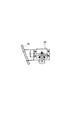
図17を参照するに、前記ハウジング39のヒンジプレート63(A,B)を取り付けた側(図9において左側)には、前記両ブラシ57(A,B)の摩耗状態を検出するための共通のセンサーとして、例えば近接センサー71がハウジング39に固定したセンサーブラケット73に固定してある。
Referring to FIG. 17, the side of the
また、前記ハウジング39には、ブラケット77に一体的に設けたコの字形の被検出軸支持体79に被検出軸81が前記近接センサー71の検出部に対して接近離反自在に軸支してある。
In addition, in the
前記被検出軸支持体79のコの字形部分の内側に位置する前記被検出軸81には、スナップリング83が嵌合してあり、このスナップリング83と被検出軸支持体79の近接センサー71側との間に前記被検出軸81を前記近接センサー71の検出部から離反する方向に付勢する圧縮スプリング85が弾装してある。
A
圧縮スプリング85が弾装された上記状態において、被検出軸81一端部は前記近接センサー71の検出範囲に近接した位置まで延伸しており、他端部は被検出軸支持体79のコの字形の外部に延伸し、前記被検出軸81の軸径より大きなドッグ係合部81Dが設けてある。また、被検出軸支持体79のコの字形部分の外側に位置する前記被検出軸81には、被検出軸81の戻り位置を規制するためのスナップリング87が被検出軸81の軸に嵌合してある。
In the above state where the
上記構成において、前記被検出軸81は付勢手段の一例としての圧縮スプリング85により常時近接センサー71から離反する方向に付勢されており、被検出軸81のスナップリング87が被検出軸支持体79に係合することにより、被検出軸81と近接センサー71との間隙が一定に保持されている。例えば、実施例での間隙は3.0mmに保持されるようになっている。
In the above configuration, the detected
一方、前記ブラシ支持体61(A,B)の帯鋸刃23U側の側面には、前記第2回転駆動軸47(A,B)に平行に延伸するストッパー部材89がそれぞれボルト90により固定してある。また、前記ヒンジプレート63(A,B)には、ストッパー部材89の第2回転駆動軸47(A,B)側の端部に当接可能な調節ねじ91が螺合してある。
On the other hand, on the side surface of the brush support 61 (A, B) on the band saw
また、前記ストッパー部材89のそれぞれには、帯鋸刃23U側へ延びる押圧レバー93が一体的に設けてあり、この押圧レバー93に前記被検出軸81のドッグ係合部81Dに先端部が当接可能な止めねじ95が位置調節可能に設けてある。なお、前記ブラシ57A,57Bの摩耗量が少ない場合には、前記ストッパー部材89と調整ねじ91は離れた状態にあるものである。
Further, each of the
上記構成により、前記ブラシ57(A,B)の何れか一方または両方が摩耗した場合、図17に示すように、前記引張りスプリング69の付勢力により、ブラシ57(A,B)が帯鋸刃23U側へ移動すると同時に、前記被検出軸81のドッグ係合部81Dに止めねじ95が当接して被検出軸81を押圧することになる。
With the above configuration, when one or both of the brushes 57 (A, B) are worn, the brush 57 (A, B) is moved to the band saw
上記構成により、前記調節ねじ91でストッパー部材89の当接位置を適宜に調節することにより、ブラシ57(A,B)が最小径となる最大摩耗量を一定に保持調節することができる。
With the above configuration, by adjusting the contact position of the
また、ブラシ57(A,B)の何れか一方または両方の摩耗が使用限界まで進行した場合、前記被検出軸81と前記近接センサー71の間隔が検出範囲に入るように接センサー71の位置を設定してあり、ブラシ57(A,B)の交換時期を自動的に検出できるようになっている。
Further, when the wear of one or both of the brushes 57 (A, B) progresses to the use limit, the position of the
また、切断加工時においては、ブラシ57(A,B)は前記引張りスプリング69の付勢力により帯鋸刃23Uの両側に一定の押圧力で押圧された状態に保持されているので、特別に切粉除去位置へ位置決めするストッパー部材が不要である。
Further, at the time of cutting, the brush 57 (A, B) is held in a state of being pressed with a constant pressing force on both sides of the band saw
1 横型帯鋸盤
3 ベースフレーム
5F 固定バイスジョウー
5M 可動バイスジョー
7L、7R ガイドポスト
9 連結部材
11L、11R スライドスリーブ
13L、13R ホイールブラケット
13A 上部ブラケット
13B 下部ブラケット
14 ビーム部材
15 回転軸
17 駆動ホイール
19 回転軸
21 従動ホイール
23 環状帯鋸刃
23U 上側走行部
23L 下側走行部
25 張力付与手段
27 上下動用アクチュエータ
27P ピストンロッド
31(L、R) ブラシ
33 ギヤードモータ
35 モータハウジング
37 ボルト
39 ハウジング
41 軸受け
43 主回転駆動軸
45 出力軸
47 カップリング
49 軸受
51(A,B) 駆動傘歯車
53(A,B) 従動傘歯車
55 ユニバーサルジョイント
57(A,B) ブラシ
59(A,B) ブラシ軸
60 蝶ナット
61(A,B) ブラシ支持体
63(A,B) ヒンジプレート
65 ヒンジピン
67(A,B) スプリングフック
69 引張りスプリング
71 近接センサー
73 センサーブラケット
75 なし
77 ブラケット
79 被検出軸支持体
81 被検出軸
83、87 スナップリング
85 圧縮スプリング
89 ストッパー部材
91 調節ねじ
93 押圧レバー
95 止めねじ
L 中心線
O 交点
S 軸心
W 被切断材
DESCRIPTION OF SYMBOLS 1 Horizontal type band saw 3
Claims (4)
Priority Applications (1)
| Application Number | Priority Date | Filing Date | Title |
|---|---|---|---|
| JP2005054253A JP4054026B2 (en) | 2004-03-01 | 2005-02-28 | Chip removal device for band saw machine |
Applications Claiming Priority (2)
| Application Number | Priority Date | Filing Date | Title |
|---|---|---|---|
| JP2004055990 | 2004-03-01 | ||
| JP2005054253A JP4054026B2 (en) | 2004-03-01 | 2005-02-28 | Chip removal device for band saw machine |
Publications (3)
| Publication Number | Publication Date |
|---|---|
| JP2005279921A JP2005279921A (en) | 2005-10-13 |
| JP2005279921A5 JP2005279921A5 (en) | 2007-09-13 |
| JP4054026B2 true JP4054026B2 (en) | 2008-02-27 |
Family
ID=35178839
Family Applications (1)
| Application Number | Title | Priority Date | Filing Date |
|---|---|---|---|
| JP2005054253A Active JP4054026B2 (en) | 2004-03-01 | 2005-02-28 | Chip removal device for band saw machine |
Country Status (1)
| Country | Link |
|---|---|
| JP (1) | JP4054026B2 (en) |
Families Citing this family (4)
| Publication number | Priority date | Publication date | Assignee | Title |
|---|---|---|---|---|
| JP5216394B2 (en) * | 2008-04-11 | 2013-06-19 | 株式会社アマダ | Chip removal device for band saw machine |
| CN104096902A (en) * | 2013-04-10 | 2014-10-15 | 成都振中电气有限公司 | Platform with dedusting function for plate cutting machine |
| CN104096903A (en) * | 2013-04-10 | 2014-10-15 | 成都振中电气有限公司 | Cutting machine platform with cleaning and conveying functions |
| CN104416619A (en) * | 2013-08-22 | 2015-03-18 | 石狮市源泰五金商贸有限公司 | Novel woodworking band sawing machine convenient for clearing sawdust |
-
2005
- 2005-02-28 JP JP2005054253A patent/JP4054026B2/en active Active
Also Published As
| Publication number | Publication date |
|---|---|
| JP2005279921A (en) | 2005-10-13 |
Similar Documents
| Publication | Publication Date | Title |
|---|---|---|
| KR100803242B1 (en) | Chip removing device of band saw machine | |
| JP4538459B2 (en) | Apparatus for machining, in particular cutting, tubular and circular sections | |
| JP4054026B2 (en) | Chip removal device for band saw machine | |
| US9662799B2 (en) | Band saw | |
| JP5216394B2 (en) | Chip removal device for band saw machine | |
| US5964135A (en) | Sawdust removing apparatus for saw machine | |
| JP4776255B2 (en) | Band saw machine | |
| JP3344733B2 (en) | Chip removal equipment for sawing machines | |
| JP2859701B2 (en) | Chip removal equipment for sawing machines | |
| JP2690959B2 (en) | Spindle device of machine tool | |
| JP2749595B2 (en) | Replacement method of band saw blade in vertical band saw machine and vertical band saw machine | |
| JP2020189321A (en) | Traveling carriage | |
| JP4276870B2 (en) | Sequential forming tool | |
| JPH07108415A (en) | Chip removing device for sawing machine | |
| EP0710525B1 (en) | Sawdust removing apparatus for saw machine | |
| EP0838296A2 (en) | Sawing machine including a sawdust removing device | |
| JPH0724161Y2 (en) | Copy turning device | |
| JP2002331419A (en) | Vice device in cutter | |
| JP4464698B2 (en) | Horizontal band saw machine | |
| JP3172761B2 (en) | Material feeder in section steel processing machine | |
| JP2531367Y2 (en) | Vise device | |
| JP2005007485A (en) | Feeding mechanism and machine tool | |
| JP3583197B2 (en) | Material feeder in section steel processing machine | |
| JPH09183016A (en) | Device for removing chip from sawing machine | |
| JPH1034433A (en) | Short material cutting work machine |
Legal Events
| Date | Code | Title | Description |
|---|---|---|---|
| A521 | Written amendment |
Free format text: JAPANESE INTERMEDIATE CODE: A523 Effective date: 20070801 |
|
| A621 | Written request for application examination |
Free format text: JAPANESE INTERMEDIATE CODE: A621 Effective date: 20070801 |
|
| A871 | Explanation of circumstances concerning accelerated examination |
Free format text: JAPANESE INTERMEDIATE CODE: A871 Effective date: 20070801 |
|
| A975 | Report on accelerated examination |
Free format text: JAPANESE INTERMEDIATE CODE: A971005 Effective date: 20070830 |
|
| A131 | Notification of reasons for refusal |
Free format text: JAPANESE INTERMEDIATE CODE: A131 Effective date: 20070904 |
|
| A521 | Written amendment |
Free format text: JAPANESE INTERMEDIATE CODE: A523 Effective date: 20071030 |
|
| TRDD | Decision of grant or rejection written | ||
| A01 | Written decision to grant a patent or to grant a registration (utility model) |
Free format text: JAPANESE INTERMEDIATE CODE: A01 Effective date: 20071127 |
|
| A61 | First payment of annual fees (during grant procedure) |
Free format text: JAPANESE INTERMEDIATE CODE: A61 Effective date: 20071206 |
|
| FPAY | Renewal fee payment (event date is renewal date of database) |
Free format text: PAYMENT UNTIL: 20101214 Year of fee payment: 3 |
|
| R150 | Certificate of patent or registration of utility model |
Ref document number: 4054026 Country of ref document: JP Free format text: JAPANESE INTERMEDIATE CODE: R150 Free format text: JAPANESE INTERMEDIATE CODE: R150 |
|
| FPAY | Renewal fee payment (event date is renewal date of database) |
Free format text: PAYMENT UNTIL: 20111214 Year of fee payment: 4 |
|
| FPAY | Renewal fee payment (event date is renewal date of database) |
Free format text: PAYMENT UNTIL: 20121214 Year of fee payment: 5 |
|
| FPAY | Renewal fee payment (event date is renewal date of database) |
Free format text: PAYMENT UNTIL: 20131214 Year of fee payment: 6 |
|
| S533 | Written request for registration of change of name |
Free format text: JAPANESE INTERMEDIATE CODE: R313533 |
|
| R350 | Written notification of registration of transfer |
Free format text: JAPANESE INTERMEDIATE CODE: R350 |
|
| S533 | Written request for registration of change of name |
Free format text: JAPANESE INTERMEDIATE CODE: R313533 |
|
| R350 | Written notification of registration of transfer |
Free format text: JAPANESE INTERMEDIATE CODE: R350 |