JP4053228B2 - ECC code mechanism for detecting stuck-at-wire failures - Google Patents
ECC code mechanism for detecting stuck-at-wire failures Download PDFInfo
- Publication number
- JP4053228B2 JP4053228B2 JP2000327211A JP2000327211A JP4053228B2 JP 4053228 B2 JP4053228 B2 JP 4053228B2 JP 2000327211 A JP2000327211 A JP 2000327211A JP 2000327211 A JP2000327211 A JP 2000327211A JP 4053228 B2 JP4053228 B2 JP 4053228B2
- Authority
- JP
- Japan
- Prior art keywords
- counter value
- bits
- data
- message
- ecc
- Prior art date
- Legal status (The legal status is an assumption and is not a legal conclusion. Google has not performed a legal analysis and makes no representation as to the accuracy of the status listed.)
- Expired - Fee Related
Links
- 230000007246 mechanism Effects 0.000 title description 28
- 230000005540 biological transmission Effects 0.000 claims description 25
- 238000000034 method Methods 0.000 claims description 16
- 238000001514 detection method Methods 0.000 description 28
- 238000012937 correction Methods 0.000 description 10
- 125000004122 cyclic group Chemical group 0.000 description 10
- 230000007704 transition Effects 0.000 description 8
- 238000010586 diagram Methods 0.000 description 3
- 238000004891 communication Methods 0.000 description 2
- 239000000470 constituent Substances 0.000 description 1
- 238000010276 construction Methods 0.000 description 1
- 230000000694 effects Effects 0.000 description 1
- 238000004193 electrokinetic chromatography Methods 0.000 description 1
- 239000011159 matrix material Substances 0.000 description 1
- 238000012986 modification Methods 0.000 description 1
- 230000004048 modification Effects 0.000 description 1
- 230000000737 periodic effect Effects 0.000 description 1
- 230000008569 process Effects 0.000 description 1
- 238000012545 processing Methods 0.000 description 1
- 238000011084 recovery Methods 0.000 description 1
- 238000006467 substitution reaction Methods 0.000 description 1
Images


Classifications
-
- G—PHYSICS
- G11—INFORMATION STORAGE
- G11B—INFORMATION STORAGE BASED ON RELATIVE MOVEMENT BETWEEN RECORD CARRIER AND TRANSDUCER
- G11B20/00—Signal processing not specific to the method of recording or reproducing; Circuits therefor
- G11B20/10—Digital recording or reproducing
- G11B20/18—Error detection or correction; Testing, e.g. of drop-outs
- G11B20/1816—Testing
-
- G—PHYSICS
- G11—INFORMATION STORAGE
- G11B—INFORMATION STORAGE BASED ON RELATIVE MOVEMENT BETWEEN RECORD CARRIER AND TRANSDUCER
- G11B20/00—Signal processing not specific to the method of recording or reproducing; Circuits therefor
- G11B20/10—Digital recording or reproducing
- G11B20/18—Error detection or correction; Testing, e.g. of drop-outs
Landscapes
- Engineering & Computer Science (AREA)
- Signal Processing (AREA)
- Detection And Prevention Of Errors In Transmission (AREA)
- Testing Of Short-Circuits, Discontinuities, Leakage, Or Incorrect Line Connections (AREA)
- Detection And Correction Of Errors (AREA)
- Error Detection And Correction (AREA)
- Monitoring And Testing Of Transmission In General (AREA)
Description
【0001】
【発明の属する技術分野】
本発明は、一般に、エラー訂正コードに関し、より詳細には、配線故障、特に縮退故障(stuck-at-fault)による配線故障を検出するエラー訂正コードに関する。
【0002】
【従来の技術】
従来技術において、配線を介して伝送されるデータは、エラーを生じやすい。すなわち、2進数の1が歪んで2進数の0として現れ、またその逆の場合もある。エラーは、データストリームの1ビットがエラーとなるシングルビットエラーの場合もあり、データストリームの2ビットがエラーとなるダブルビットエラーの場合もある。なお、典型的には、データは、1本の配線ではなく1組の配線を介して伝送されるが、1本及び複数本の配線伝送システムのいずれにおいても、エラーが生じる可能性がある。さらに、データは、配線の数よりはるかに多いため、複数サイクルで送信され、たとえば、16本の配線が4回のサイクルで64ビットを送信する。したがって、複数サイクルでエラーが生じるおそれがある。システムの中には、データをパケット化する、すなわち、特定のサイズのデータパケットでデータを送出する、ものもある。したがって、異なるデータパケットでエラーが生じる可能性がある。典型的なエラーの原因の1つは、配線故障である。配線のショートまたは断線により、故障信号が配線で送出され得る。これらの故障は、2つのタイプのうちの一つに分類される。第1のタイプは、配線が1縮退故障(stuck-at-one)または0縮退故障(stuck-at-zero)である場合である。この場合、入力に関係なく、配線は、1(1縮退故障の場合)またはゼロ(0縮退故障の場合)のみを中継し、信号を切り換えることはない。第2のタイプは、悪質な(malicious)故障である。このタイプの故障では、入力がどうであれ配線の出力が切り替わっていく。たとえば、入力がゼロの場合、配線出力は1またはゼロのいずれかとなり、入力が1であっても、配線出力は1またはゼロのいずれかとなる。すなわち、配線の挙動は予測不能である。さらに、配線故障が正しい結果を搬送することがあるため、エラーが隠されてしまう場合がある。
【0003】
かかるエラーを検出するために、ECCコードをデータとともに伝送する。巡回符号は、配線故障を検出することができるECCコードの一種である。巡回符号は、重要なコードのクラスである。これらのコードのジェネレータ/パリティマトリクスは、行(row)の周期的なシフトにより形成される。これらは、多数のランダムエラー、バイトエラーおよびバーストエラーを検出/訂正するのに効率的な巡回符号である。巡回符号については、T.R.N., RaoおよびE. Fujiwaraによる「Error Control Coding for Computer Systems」(Prentice Hall, Englewood Cliffs, New Jersey 07632,ISBN 0-13-28395-9)に詳細が記載されており、参照によりこれを本明細書中に組み込む。巡回符号は、悪質な故障を検出することを目的としており、従って、故障は、悪質な故障であると推定する。巡回符号は後者を対象にしているため、縮体故障を検査する場合よりも多くのビットを必要とし、必要なビット数は、設計者が残しておかなければならないビット数より多いことがある。たとえば、32バイト(=256ビット)からなるデータメッセージを想定する。シングルビットエラー訂正およびダブルビットエラー検出を可能にするために、10ビットが余分に必要であり、シングルエラー訂正には9ビットが必要となるが、これは、29が(256+9)より大きい2のべき数のうち最も小さいベキ数であるからである。10番目のビットは、ダブルビットエラーを検出するために使用され、合計266ビットになる。したがって、シングルエラー訂正およびダブルエラー検出を行うために10ビットが必要になる。これら266ビットを10本の配線で送る場合、6本の配線が27ビットを搬送し、4本の配線が26ビットを搬送する。したがって、配線故障が最大27ビットに影響を及ぼす。悪質な配線故障を検出するために、27の追加ビットが必要となるが、これについては、RaoおよびFujiwaraによる前記書籍にある、(γ度の)g(x)により生成された巡回符号が、長さγ以下の任意のバーストを検出できるという定理3.7を参照されたい。これにより、合計293ビットで、配線故障に加えて2本の連続配線にわたる長さ27以下の任意のバーストを検出する。したがって、合計37ビットがエラー検出に必要となる。これによるオーバーヘッドは大きく、伝送用のシステム資源の多くの部分が消費される。
【0004】
37ビットは293ビットのわずか13%にすぎないが、より高い割合のオーバヘッドは、エラー検出、特にデータをブロックまたはパケットで伝送する時に必要な余分なビットに起因することがある。たとえば、1ブロックのデータが、10本の配線にわたる7サイクルのデータで構成され、1ブロックあたり合計70ビットであるとする。このとき、256ビットでは4ブロック(3.6ブロックを切り上げる)、293ビットでは5ブロック(4.1ブロックを切り上げる)がそれぞれ必要となる。したがって、エラー検出には余分なブロック、すなわち20%の余分なビットが必要になる。
【0005】
データ伝送にオーバヘッドが生じることに加え、巡回符号は、実施するのがより複雑である。受信側でデコードすることは、巡回符号を実施するための多くの異なる手段が存在するので複雑である。
【0006】
【発明が解決しようとする課題】
したがって、大きなオーバヘッドを生じず、かつ、実施が容易な配線縮退故障を検出するエラー検出メカニズムが当該技術において必要とされている。
【0007】
【課題を解決するための手段】
これら及びその他の目的、特徴および技術的利点は、エラー検出メカニズム(エラー検出手段)を用いて配線縮退故障を検出するシステムおよび方法により達成される。本メカニズムを用いて、配線縮退故障検出が可能な既存のECCコードを強化することが可能である。たとえば、既存のECCコードは、データ伝送においてランダムなシングルエラーやダブルエラー(SEC−DED)を検出できるが、一方、本発明のメカニズムは、配線故障を検出し、その故障した配線上を伝送されたデータのエラーを特定する。本発明のメカニズムは、メッセージ用の既存のECCコードを含む、メッセージ内の1(または0)の数を決定して、この情報をそのメッセージに付加する。このカウント値は、それ自体、メッセージに使用される同一のECCコードにより保護される。受信側でメッセージを復号化(デコード)する場合、任意の配線障害による縮退故障(縮退故障配線障害、配線縮退故障)が、付加された情報をメッセージの内容と比較することにより検出される。
【0008】
本メカニズムは、配線縮退故障を検出することに加え、復号後のデータ部分において、0から1への遷移数が1から0への遷移数に等しくない場合、任意の数の複数エラー検出することもできる。従来技術の巡回符号に対する本発明のメカニズムの利点は、必要なチェックビットの数が少なくて済むことと、実施が比較的簡単であること、そして、必要な追加チェックビットの数と配線故障検出をトレードオフできることである。本発明のメカニズムは、コードワードが、配線故障が生じている状態で複数サイクルにわたって伝送される際に生じる複数エラーの検出に特に有用である。
【0009】
本発明のメカニズムは、縮退故障および最も悪質な配線故障を検出するものである。本発明のメカニズムは、すべての悪質な配線故障を検出するものではなく、特に、ECC復号後に0から1への遷移数が1から0への遷移数と等しい場合には、配線故障を検出しない。したがって、本発明は、データ伝送において、1または0の数を変化させる予測可能な故障、たとえば、配線が0または1に固定される縮退故障、を検出することを主な目的とする。本発明のメカニズムは、データ伝送において使用される配線数に応じてスケーリングすることが可能である。
【0010】
以上、以下の発明の詳細な説明をよりよく理解できるように、本発明の特徴および技術的利点をかなり広義に概説した。本発明の特許請求の範囲の主題を構成する本発明の他の特徴および利点を以下で説明する。なお、開示された概念および特定の実施形態を、本発明と同じ目的を実施するための他の構造を修正または設計する基本として、容易に利用することができるということは当業者には明らかであろう。また、かかる等価な構成が、特許請求の範囲に記載される本発明の思想および範囲から逸脱しないことも当業者には理解されるはずである。
【0011】
【発明の実施の形態】
本発明およびその利点をより十分に理解できるようにするために、添付図面を参照して以下に説明する。
【0012】
本発明のエラー検出メカニズムは、図1に示すようにメッセージを符号化する。本発明のメカニズムにより、エラー訂正コード(ECC)(もしあれば)が、実データに作用する(または、演算を施す)ことができる(11)。次に、本メカニズムは、データビットおよび関連するECCチェックビット(もしあれば)を、その「データ」として処理し、これを配線縮退故障から保護する。本発明のメカニズムは、データ部分、すなわち、実データおよびチェックビットにおける1の数をカウントし(12)、この数をカウンタ値として記憶する。本発明のメカニズムは、カウンタ値がデータ部分と同一のECC方式により保護されるようにECCチェックビットを追加する(13)ことによってカウンタ値ビットを保護することができる。したがって、本発明のメカニズムは、4つの部分、すなわち、図2に示すように、実データ部21と、実データを保護するECCチェックビット22と、実データとそのチェックビットにおける1の数を有するカウンタ値23と、データ部と同一のECC能力でカウンタ値を保護するチェックビット24とから構成されるデータメッセージ20を形成する(14)。したがって、伝送メッセージは、実データ、実データECC、カウンタ値およびカウンタ値ECCで符号化される。そしてメッセージは、伝送線または他の伝送システムを介して目的地に伝送される。なお、シングルエラー訂正およびダブルエラー検出(SEC−DED)コードのECC能力に関して本発明を説明したが、本発明は、パリティを含む任意のECCコードを用いて動作することもできる。さらに、1の数をカウントすることに関して本発明を説明したが、本発明は、1をカウントする代わりに0をカウントすることによって演算することもできる。
【0013】
メッセージの宛先に配置される本発明のメカニズムの第2の例は、図3に示すようにメッセージを復号化する。復号時、メッセージは2つのサブメッセージに分割される(31)。第1のサブメッセージは実データと実データECCからなり、第2のサブメッセージはカウンタ値とカウンタ値ECCからなる。第1および第2のサブメッセージは、次に符号化に使用されたECCメカニズムにしたがって別々に復号される(32)。実データまたはカウンタ値のいずれかにシングルビットエラーがあれば、これを検出してそれぞれのECCにより訂正する(33)。実データまたはカウンタ値のいずれかにダブルエラーがあれば、それぞれのECCによりこれを検出する(33)。ダブルエラーが発見されると、メッセージは破棄され、再送またはリトライ信号がメッセージの送信元に送信される。SEC−DEDが完了すると、配線故障を検出することができる。次に、本発明のメカニズムは、復号化された実データと実データECCにおける1の数をカウントする(34)。復号化されたカウンタ値を、復号化された実データと実データECCチェックビットにおいてカウントされた1の数と比較(35)して、配線縮退故障が存在するか否かを判定する(36)。このチェックにおいて、悪質な配線故障を含む複数エラーが存在していれば、複数エラーが相殺されない限り、これも検出される。なお、悪質な配線故障では、故障した配線により伝送された値がランダムに変更される。複数エラーの相殺は、0から1への遷移数が1から0への遷移数と等しい場合に起こる。カウンタ値が実データと実データECCにおける1の数と一致しない場合、エラーが通知される(または、エラーフラグが立てられる)(37)。配線エラーが検出されると、データは破損された(データに誤りがある)とみなされる。別のシステムでは別のエラー回復メカニズムを呼び出すことができる。配線エラーが検出されなかった場合は、メッセージの伝送中に検出可能なエラーが発生しなかった(38)ということになる。
【0014】
たとえば、64ビットの実データを有するメッセージパケットを転送する、17ビット幅、すなわち17本の配線幅のチャンネルを考える。さらに、すべてのシングルエラーが訂正され、すべてのダブルエラーが検出され、配線故障が検出されると想定する。SEC−DEDコードでは、(72,64)ECCコードを形成する8チェックビットが必要とされる。このコードは、配線故障を検出する能力を有していないため、最大5つのエラーを招く可能性がある。ここで、72ビットは17本の配線上で送信されるため、少なくとも1本の配線がメッセージの5ビットを搬送し、この配線が故障すると、最大5つのエラーが発生することに留意されたい。実データと実データECCとを足すと72ビットであるので、実データと実データECCとを合わせて、合計72個の1を有することがある。したがって、カウンタ値は7ビット値になる。カウンタ値自体は、(12,7)SEC−DED ECCコードを形成する5ビットのECCにより保護される。このため、本発明のメカニズムにより形成されるメッセージは84ビットであり、このうち64ビットが実データである。メッセージは、(84,64)コードとなる。符号化されたメッセージは、(チャンネルが17本の配線で構成されるため)チャンネルを介して5サイクルにわたって伝送される。
【0015】
カウンタ値は、実データと同一のECCで保護されるため、メッセージ全体は、所望のECC(この場合、SEC−DED)で保護されることが保証される。たとえば、カウンタ値がECCで保護されないとすると、カウンタ値のシングルビットエラーにより、実データに実データECCを加えたもの(以下ではこれを、実データ+実データECCとも記載)に対する1の数に不整合が生じる。この不整合により、誤った配線故障フラグが発光される。さらに、配線エラーは、検出にかからないエラーパターンで発生する場合がある。たとえば、3つのエラーが実データ+実データECCの72ビットにあり、1つのエラーがカウンタ値にある、合計4つのエラーをもたらす配線故障によるエラーパターンがある。(72,64)ECCは、3つのエラーの検出を保証しないため、復号化されたビットパターンに2つまたは4つのエラーが生じうる。カウンタ値のビットの1つが変化すると、誤ったデータが伝送される可能性がある。また、配線故障に伴う他のエラーパターンが検出されない可能性もある。このため、カウンタ値をいくつかのECCで保護することで、これらの問題を防止する。
【0016】
しかしながら、カウンタ値にカウンタ値ECCを加えたもの(以下ではこれを、カウンタ値+カウンタ値ECCとも記載)が同一配線上で2ビットを越えることはない。たとえば、伝送用に17本の配線があれば、SEC−DED ECCの場合、カウンタ値+カウンタ値ECCが34ビットを越えることはない。すなわち、カウンタ値+カウンタ値ECCが、伝送チャンネルの配線幅の2倍を越えることはない。この制限により、配線故障によるカウンタ値のエラーは、ECCにより確実に検出される。このため、カウンタ値の任意のシングルエラーは訂正され、カウンタ値の任意のダブルエラーは、それが、偶発故障または配線故障によるものであっても、検出することができる。したがって、カウンタ値は、シングルエラー訂正、ダブルエラー検出および配線故障検出により保護される。なお、この制限は、使用されるECCのタイプが、メッセージのサイズならびに検出可能なエラー数にも影響を及ぼすため、使用されるECCのタイプによって異なる。たとえば、シングルエラー検出(SED)ECCを使用する場合、シングルエラーのみが検出可能であるため、カウンタ値とカウンタ値ECCを加えたものが配線サイズを超えることはないが、ECCのサイズは、SEDのビット数がSEC−DEDより少ないことから小さくなる。実データ上で使用されるECCがパリティビットの場合、カウンタ(値)自体およびパリティビットが配線故障に対して保護されるとすれば、パリティビットによりカウンタ値を保護するだけで十分である。一般に、カウンタ値とカウンタ値ECCを足したもののサイズは、チャンネルのサイズに、ECCにより検出可能なエラー数を掛けたもののサイズより大きくはない。なお、異なるタイプのECCを使用することもできる。たとえば、SEC−DED ECC、SED ECCまたはダブルエラー訂正―トリプルエラー検出ECCコード、あるいはその他任意のタイプのECCコードによりデータを保護するこができる。
【0017】
しかしながら、本発明のエラー検出メカニズムは、カウンタ値とカウンタ値ECCの合計が上記の制限を上回る状況に適応できるように再構成可能である。たとえば、上述の(72,64)コードを用い、チャンネルを17ビット幅ではなく5ビット幅にする。カウンタ値およびカウンタ値ECCのサブメッセージは依然として合計12ビットであり、(12,7)コードが形成される。このため、サブメッセージの2ビットが、3番目のサイクルで伝送される(すなわち、最初の2サイクルで10ビットが送信される)。3ビットが少なくとも1本の配線で送信されると、SEC−DED ECCは、カウンタ値の精度を保証することができない。
【0018】
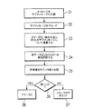
第1の解決策は、各カウンタ値それぞれがECCチェックビットを有する複数のカウンタ値を使用することである。たとえば、ECCがSEC−DEDの場合、カウンタ値およびカウンタ値ECCチェックビットが配線幅の2倍より大きいときは、第1のカウンタ値とそのECCチェックビットにおける1の数をカウントすることによって第2のカウンタ値が形成される。第2のカウンタ値は、ECCチェックビットを添付される。このプロセスは、最後のカウンタ値とそのECCチェックビットが配線幅の2倍より小さくなるまで再帰的(recursively)に続行される。第1のカウンタ値は(log k)ビットを有する。ここで、kは情報ビットの数である。第2のカウンタ値は、必要であれば、(log(log k))ビットを有する。図5は、上記例による第1の解決策を示したものであり、SEC−DED ECCビットを含む、72個のデータビット51、d0…d71と、SEC−DED ECCビットを含む12個の第1のカウンタ値ビット52、C0…C11と、を含むデータパケットメッセージ50が形成されている。この例では第2のカウンタ値が必要とされる。第2のカウンタ値は、第1のカウンタ値における1の数を保持するものであり、12ビットコードにおける1の数を保持するために4ビット幅である必要がある。4ビットの第2のカウンタ値を保護するために、4ビットのECCが必要とされる。これにより、(8,4)SEC−DEDコード53、すなわちAC0…AC7が形成される。これらの8ビットは、2サイクルで5本の配線上を伝送可能である。第2のカウンタ値および第2のカウンタ値ECCを3サイクルより少ないサイクルで伝送可能であるため、第3のカウンタは必要ではない。なお、このコードは、第3のサブメッセージを形成し、他の2つのサブメッセージとは別々に復号化される。したがって、合計20ビットのカウンタ値およびカウンタ値ECCが実データおよび実データECCに添付される。
【0019】
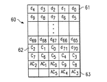
第2の解決策は、カウンタ値を追加せずに、第1のカウンタ値ECCの選択されたビットを別々に保護するものである。カウンタ値の該ビットは、ECC後に、任意のグループにおける合計ビット数がチャンネル幅の2倍を超えないように別々のグループで符号化される。すなわち、カウンタ値の該ビットは複数のECCコードに分割される。図6は、この例による第2の解決策を示すものであって、SEC−DED ECCビットを含む、72個のデータビット61、d0…d71と、SEC−DED ECCビットを含む10個の第1のカウンタ値ビット62、C0…C9と、を含むデータパケットメッセージ60が形成されている。第1の解決策の場合、カウンタ値とECC52を足したものが12ビット幅であったが、この例では、コードの全サイズを最大10ビットとすることができる。7ビットのカウンタ値の5ビットは、5ビットのECCにより保護可能であり、このため、(10,5)SEC−DED ECCコード62が形成される。なお、10ビットは2サイクルで伝送されるため、この(10,5)コードで十分である。カウンタ値の残りの2ビットは、4ビットのECCで保護され、このため(6,2)コード63が形成される。したがって、本解決策により、合計16ビットのカウンタ値およびカウンタ値ECCが実データおよび実データECCに添付されることになる。なお、この例では、第2の解決策は、第1の解決策より良好な結果をもたらすが、値が異なると結果も異なる。いずれの解決策においても、カウンタ値は保護される。
【0020】
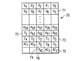
以下に別の例を挙げる。64ビットが5本の配線を用いて伝送され、所望のエラー検出により、配線縮退故障に加えて、任意のシングルエラーも検出する場合を考える。この場合、シングルエラー検出メカニズムは、65ビット(データに64ビット+パリティビットに1ビット)を必要とする。図7は、第1の解決策における、例として64ビットであるメッセージデータパケット70を示しており、このパケットは、64個のデータビット71、d0…d63と、データビット71に対するパリティビットPd72とを含む。このため、65ビットが5本の配線で伝送されることにより、7ビット幅のカウンタビット、すなわちC0〜C673が必要とされる。これらの7ビットのカウンタビットは、別のパリティビットであるPC74により保護され、従って8ビットが必要となる。これらの8ビットは配線故障を受けやすい(1本の配線を2回通過するビットもある)ため、4ビット幅、すなわちAC0〜AC375の第2のカウンタが必要であり、パリティPAC76がこのカウンタビットを合計5ビットで保護する。5本の配線があるため、さらに多くのカウンタは必要ない。第2の解決策は、7ビットカウンタの4ビットを取り、パリティがこれを保護するものである(図8)。残りの3ビットはパリティを別に保護するためのものである。図8は、第2の解決策において、例として64データビットを有するメッセージデータパケット80を示しており、このパケットは、64個のデータビット81、d0…d63と、データビット81に対するパリティビットPd82とを含む。このため、65ビットが5本の配線で伝送されることにより、7ビットの幅を有するカウンタが必要とされる。第2の解決策は、最大サイズが5ビットとなるように、5本の配線でカウンタ(値)を複数部分に分割する。1つのパリティビットが保護用に必要とされるため、カウンタ(値)は最大4ビットのセグメントに分割される。このため、カウンタ(値)の4ビットC0〜C383がパリティビットPCL84により保護され、カウンタ(値)の3ビットC4〜C6がパリティビットPCH85により保護される。なお、カウンタ(値)は下位4ビットと上位3ビットにセグメント化されるものとして図示されているが、他の分割も可能である。配線(縮退)故障検出によってシングルエラーがカバーされるため、パリティビットはシングルエラーを検出するためには不要である。しかしながら、それらは、配線故障検出がすべてのタイプのECC(たとえば、SEC−DED)をカバーし得ないため一例として使用される。
【0021】
第3の解決策は、カウンタ値のサイズを縮小する、すなわち、幅がより小さいカウンタ値を使用することである。カウンタ値が小さいと、サブメッセージが小さくなる。さらに、カウンタ値が小さいと、保護に必要なECCビットが少なくなり、この結果サブメッセージが小さくなる。上述の例において、チャンネルが17ビット幅であって、64ビットの実データと8ビットのECCチェックビットを有するメッセージパケット90を転送し、図9に示すような(72,64)コードを形成する場合を考える。なお、72ビットは17の配線上を5サイクルで送信されるため、少なくとも1本の配線が5ビットのメッセージを搬送し、この配線が故障または縮退故障した場合は、5つのエラーが発生する。従って、配線縮退故障は、−5(すなわち、配線は0に固定されているが、実際の値は1である場合)乃至+5(すなわち、配線は1に固定されているが、実際の値は0である場合)だけカウンタ(値)に影響を及ぼすにすぎない。したがって、幅4ビットのカウンタ(値)は、10の幅を許容できるため、この幅のカウンタ(値)で十分である。このため、カウンタ値を保護するために、前述の実施形態で必要される(12,7)コードではなく、(8,4)SEC−DED ECCコード92、すなわち、C0〜C7が必要とされる。一般に、カウンタ値は、全コードワードを伝送するサイクル数の2倍の対数(底2)の上限である幅を有する必要がある。したがって、本例では、16を法とする(モジュロ16)1の数がカウントされる。これは、1を加え、モジュロ演算を行うことにより実行されるが、カウント中は、全幅を有することになるが、送信中は、余分な上部ビットを切り離すことが可能である。第3の解決策は好ましい実施形態である。
【0022】
なお、設計者は、(チェックビットの数に換算して)検出とオーバヘッドとをトレードオフすることにより、信頼性を低くした場合に必要とされるビット数よりカウンタ値ビットを少なくすることを決定することもできる。すなわち、カウンタビットの数を、配線縮退故障検出を行うのに必要な数より少なくすることができるが、その場合は、配線縮退故障検出を保証することはできない。
【0023】
また、カウンタ値および実データビットは、チェックビットに不足がある場合、ともにECCにより保護され得る(または、結合して保護されるECCになり得る)。しかしながら、これは、配線故障または縮退故障に対する完全なカバレージを提供するものではない。たとえば、簡単なパリティ保護がなされたデータおよびカウンタ(値)があり、該データにおいて1ビットを変化させ、かつカウンタ(値)(最下位ビット)において1ビットを変化させる配線故障が発生したとする。パリティは、エラーを検出せず、カウンタ(値)もまた検出しない。従って、上記例では、カウンタ(値)に4ビットが、データに64ビットが必要とされる。これらの68ビットを保護するために、8ビットのECCデータが必要とされるため、(76,68)SEC−DED ECCコードが形成される。
【0024】
さらに、単一の配線故障を検出することができるが、0から1への遷移数が1から0への遷移数と等しい場合には、複数の配線故障を検出できない場合がある。このため、複数の配線故障のいくつかについては検出することができるが、すべての配線故障を検出できるわけではない。
【0025】
さらに、本発明は、複数の配線を含む任意のデータ伝送環境においても動作可能であり、たとえば、LAN、WANまたはインターネットを介して接続された2つのコンピュータ間でECCが使用される。また、本発明は、コンピュータシステム内部の、たとえば、RAMとCPU間のデータ伝送にも使用可能である。これは、特にマルチプロセッサシステムについていえる。
【0026】
図4は、本発明に使用されるように構成されたコンピュータシステム400を示す。データビットを送信するために使用される配線は、バス402、または405と406を結合するバス、あるいはネットワーク412である。システム400において、中央処理装置(CPU)401は、バス402に結合される。さらに、バス402は、ランダムアクセスメモリ(RAM)403、読み取り専用メモリ(ROM)404、入出力(I/O)カード405、通信カード411、ユーザインターフェースカード408およびディスプレイカード409に結合される。RAM403およびROM404は、当該技術において周知のように、ユーザとシステムデータとプログラムとを保持する。I/Oカード405は、ハードドライブ406等の記憶装置をコンピュータシステムに接続する。通信カード411は、コンピュータシステムをローカルネットワーク、広域ネットワークまたはインターネットネットワーク412に結合するよう構成されている。ユーザインターフェースカード408は、キーボード413、ポインティングデバイス407等のユーザ入力装置をコンピュータシステム400に結合する。最後に、ディスプレイカード409は、CPU401により駆動されて、表示装置410の表示を制御する。CPU401は、HP PA−8200等の任意の汎用CPUとすることができる。しかしながら、本発明は、CPU401が、本明細書において説明したような本発明の動作をサポートする限り、CPU401のアーキテクチャにより制限されるものではない。なお、エラーコード(EC)という用語は、訂正および/または検出を意味する。
【0027】
本発明およびその利点を詳細に説明してきたが、特許請求の範囲により規定される本発明の思想および範囲から逸脱することなく、本明細書で説明した事項について種々の変更、置換および修正を行うことができることが理解されよう。
以下においては、本発明の種々の構成要件の組み合わせからなる例示的な実施態様を示す。
1.データメッセージの伝送中に配線故障を検出するための方法であって、前記データメッセージ(20)は、データ部(21)と、前記データ部に関連づけられた第1のエラーコード(EC)部(22)とからなり、
前記データ部および前記第1のEC部に存在する特定ビットの数を表すカウンタ値(23)を決定するステップ(12)であって、前記特定ビットが、2進数の1と2進数のゼロからなるグループから選択される、ステップと、
前記カウンタ値に関連づけられる第2のEC部(24)を形成するステップ(13)と、
前記カウンタ値および前記第2のEC部を用いて前記データメッセージを符号化するステップ(14)と、
前記データメッセージの伝送中に、配線故障によるエラーが前記データ部に存在するか否かを判定するために、受信体が、前記符号化されたカウンタ値を使用するステップ
からなる、方法。
2.前記第1のEC部(22)および前記第2のEC部(24)が、シングルエラー訂正コードおよびダブルエラー検出コードである、上項1の方法。
3.前記第1のEC部(22)および前記第2のEC部(24)が、シングルエラー検出コードである、上項1の方法。
4.前記使用するステップが、
前記メッセージ(20)を、前記データ部(21)及び前記第1のEC部(22)からなる第1のサブメッセージと、前記カウンタ値(23)及び前記第2のEC部(24)からなる第2のサブメッセージとを有する、少なくとも2つのサブメッセージに分割するステップ(31)と、
前記第1及び第2のサブメッセージを復号化するステップ(32)と、
前記第1のサブメッセージに存在する特定ビットの数を表す別のカウンタ値を決定するステップ(34)と、
前記別のカウンタ値と前記第2のサブメッセージのカウンタ値を比較するステップ(35)と、
前記比較ステップが、前記別のカウンタ値が前記第2のサブメッセージのカウンタ値と異なることを示す場合に、エラーを通知するステップ(37)
からなる、上項1の方法。
5.前記使用するステップが、
前記第1のEC部(22)によって前記第1のサブメッセージにおけるエラーを検出するステップと、
前記第2のEC部(24)によって前記第2のサブメッセージにおけるエラーを検出するステップ
をさらに含み、
エラー検出する前記ステップが、別のカウンタ値を決定する前記ステップに先立って行われる、上項4の方法。
6.前記カウンタ値(23)と前記第2のEC部(24)のサイズが、前記メッセージの伝送時に使用される伝送経路の幅と比較して、前記第2のEC部により保護可能なサイズより大きく、
先行するカウンタ値および先行するのEC部に存在する特定ビットの数を表す次のカウンタ値を生成するステップと、
前記次のカウンタ値と関連づけられた次のEC部を形成するステップと、
前記次のカウンタ値と前記次のEC部のサイズが、前記伝送経路の幅と比較して、前記次のEC部により保護可能なサイズ程度(または、サイズ以下)になるまで、前記生成するステップと形成するステップを繰り返すステップ
からさらになる、上項1の方法。
7.前記カウンタ値(23)および前記第2のEC部(24)のサイズが、前記メッセージの伝送時に使用される伝送経路の幅と比較して、前記第2のEC部により保護可能なサイズより大きく、
前記カウンタ値を複数のカウンタ値部分に分割するステップと、
複数のEC部を形成するステップであって、各EC部が、前記複数のカウンタ値部分の特定の1つと関連づけられる、ステップ
からさらになる上項1の方法であって、前記各カウンタ値部分およびそれに関連づけられたEC部のサイズが、前記伝送経路の幅と比較して、前記関連づけられたEC部により保護可能なサイズ程度(または、サイズ以下)である、方法。
8.高次ビットを除去することにより前記カウンタ値(23)を切り捨てるステップであって、これにより、残りのビットが、前記データ部(21)および前記第1のEC部(22)を伝送するのに必要なサイクル数の2倍を示すのに十分な幅となるようにする、ステップをさらに含み、
前記切り捨てるステップが、前記第2のEC部(24)を形成する前記ステップに先立って行われる、上項1の方法。
【0028】
【発明の効果】
本発明によれば、大きなオーバヘッドを生じず、かつ、実施が容易な、配線縮退故障を検出するエラー検出メカニズムを提供することができる。
【図面の簡単な説明】
【図1】メッセージを符号化する本発明のメカニズムのフロー図を示す。
【図2】図1により符号化されたメッセージを示す。
【図3】図2のメッセージを復号化する本発明のメカニズムのフロー図を示す。
【図4】図1および図3の本発明を実施するよう構成されたコンピュータシステムのブロック図を示す。
【図5】図1の本発明の1実施態様によって形成される図2のデータメッセージの例を示す。
【図6】図1の本発明の、図5とは異なる実施態様によって形成される図2のデータメッセージの例を示す。
【図7】図1の本発明の、図5及び6とは異なる実施態様によって形成される図2のデータメッセージの例を示す。
【図8】図1の本発明の、図5、6及び7とは異なる実施態様によって形成される図2のデータメッセージの例を示す。
【図9】図1の本発明の、図5、6、7及び8とは異なる実施態様によって形成される図2のデータメッセージの例を示す。
【符号の説明】
20 データメッセージ
21 実データ部
22 ECCチェックビット(第1のEC部)
23 カウンタ値
24 ECCチェックビット(第2のEC部)[0001]
BACKGROUND OF THE INVENTION
The present invention generally relates to error correction codes, and more particularly to an error correction code for detecting wiring faults, particularly wiring faults due to stuck-at-faults.
[0002]
[Prior art]
In the prior art, data transmitted via wiring is prone to errors. That is, the binary number 1 appears distorted and appears as a
[0003]
In order to detect such an error, an ECC code is transmitted along with the data. The cyclic code is a type of ECC code that can detect a wiring failure. Cyclic codes are an important class of codes. The generator / parity matrix of these codes is formed by periodic shifts of rows. These are efficient cyclic codes for detecting / correcting a large number of random errors, byte errors and burst errors. Cyclic codes are described in detail in “Error Control Coding for Computer Systems” by TRN, Rao and E. Fujiwara (Prentice Hall, Englewood Cliffs, New Jersey 07632, ISBN 0-13-28395-9). Which is incorporated herein by reference. The cyclic code is intended to detect a malicious failure, and therefore the failure is presumed to be a malicious failure. Since the cyclic code is intended for the latter, it requires more bits than when checking for degenerate faults, and the number of bits required may be greater than the number of bits that the designer must leave. For example, a data message consisting of 32 bytes (= 256 bits) is assumed. To enable single-bit error correction and double-bit error detection, an extra 10 bits are required, and 9 bits are required for single error correction. 9 Is the smallest power number among powers of 2 greater than (256 + 9). The tenth bit is used to detect double bit errors, for a total of 266 bits. Therefore, 10 bits are required to perform single error correction and double error detection. If these 266 bits are sent over 10 wires, 6 wires carry 27 bits and 4 wires carry 26 bits. Therefore, wiring failure affects up to 27 bits. In order to detect malicious wiring faults, 27 additional bits are required, for which the cyclic code generated by g (x) in the book by Rao and Fujiwara (gamma) is See Theorem 3.7 that any burst of length γ or less can be detected. Thereby, an arbitrary burst having a length of 27 or less over two continuous wirings is detected in addition to the wiring failure in a total of 293 bits. Therefore, a total of 37 bits are required for error detection. This results in a large overhead and consumes a large part of the system resources for transmission.
[0004]
Although 37 bits is only 13% of 293 bits, a higher percentage of overhead may be due to error detection, especially the extra bits needed when transmitting data in blocks or packets. For example, it is assumed that one block of data is composed of seven cycles of data over 10 wires, and the total is 70 bits per block. At this time, 256 blocks require 4 blocks (3.6 blocks are rounded up), and 293 bits require 5 blocks (4.1 blocks are rounded up). Thus, error detection requires an extra block, ie 20% extra bits.
[0005]
In addition to the overhead in data transmission, cyclic codes are more complex to implement. Decoding on the receiving side is complicated because there are many different means for implementing the cyclic code.
[0006]
[Problems to be solved by the invention]
Therefore, there is a need in the art for an error detection mechanism that detects a stuck-at-wire fault that does not cause significant overhead and is easy to implement.
[0007]
[Means for Solving the Problems]
These and other objects, features and technical advantages are achieved by a system and method for detecting a stuck-at-wire fault using an error detection mechanism (error detection means). By using this mechanism, it is possible to strengthen an existing ECC code that can detect a stuck-at fault in a wiring. For example, existing ECC codes can detect random single errors and double errors (SEC-DED) in data transmission, while the mechanism of the present invention detects a wiring failure and is transmitted over the failed wiring. Identify data errors. The mechanism of the present invention determines the number of 1s (or 0s) in the message, including the existing ECC code for the message, and appends this information to the message. This count value is itself protected by the same ECC code used for the message. When a message is decoded (decoded) on the receiving side, a stuck-at fault due to an arbitrary wiring fault (a stuck-at fault wiring fault or a wiring stuck-at fault) is detected by comparing the added information with the content of the message.
[0008]
This mechanism detects an arbitrary number of multiple errors when the number of transitions from 0 to 1 is not equal to the number of transitions from 1 to 0 in the data portion after decoding in addition to detecting a stuck-at-wire fault. You can also. The advantages of the mechanism of the present invention over the prior art cyclic codes are that fewer check bits are required, that it is relatively simple to implement, and that the number of additional check bits required and wiring fault detection are reduced. It can be traded off. The mechanism of the present invention is particularly useful for detecting multiple errors that occur when a codeword is transmitted over multiple cycles in the presence of a wiring failure.
[0009]
The mechanism of the present invention detects stuck-at faults and the most vicious wiring faults. The mechanism of the present invention does not detect all malicious wiring faults, especially when the number of transitions from 0 to 1 is equal to the number of transitions from 1 to 0 after ECC decoding. . Therefore, the main object of the present invention is to detect a predictable fault that changes the number of 1 or 0 in data transmission, for example, a stuck-at fault in which the wiring is fixed to 0 or 1. The mechanism of the present invention can be scaled according to the number of wires used in data transmission.
[0010]
The foregoing has outlined rather broadly the features and technical advantages of the present invention in order that the detailed description of the invention that follows may be better understood. Additional features and advantages of the invention will be described hereinafter that form the subject of the claims of the invention. It will be apparent to those skilled in the art that the disclosed concepts and specific embodiments can be readily utilized as a basis for modifying or designing other structures for carrying out the same purposes of the present invention. I will. It should also be understood by those skilled in the art that such equivalent constructions do not depart from the spirit and scope of the invention as set forth in the claims.
[0011]
DETAILED DESCRIPTION OF THE INVENTION
In order that the present invention and its advantages may be more fully understood, the following description is made with reference to the accompanying drawings.
[0012]
The error detection mechanism of the present invention encodes a message as shown in FIG. The mechanism of the present invention allows an error correction code (ECC) (if any) to act on (or perform an operation on) actual data (11). The mechanism then treats the data bits and associated ECC check bits (if any) as their “data” and protects them from wire stuck-at faults. The mechanism of the present invention counts the number of 1s in the data portion, ie, the actual data and check bits (12) and stores this number as a counter value. The mechanism of the present invention can protect the counter value bits by adding 13 ECC check bits so that the counter value is protected by the same ECC scheme as the data portion. Therefore, the mechanism of the present invention has four parts, namely, as shown in FIG. 2, a
[0013]
A second example of the mechanism of the present invention located at the message destination decodes the message as shown in FIG. Upon decoding, the message is divided into two submessages (31). The first sub message includes actual data and actual data ECC, and the second sub message includes a counter value and a counter value ECC. The first and second submessages are then decoded separately according to the ECC mechanism used for encoding (32). If there is a single bit error in either the actual data or the counter value, it is detected and corrected by the respective ECC (33). If there is a double error in either the actual data or the counter value, this is detected by the respective ECC (33). If a double error is found, the message is discarded and a retransmission or retry signal is sent to the source of the message. When the SEC-DED is completed, a wiring failure can be detected. Next, the mechanism of the present invention counts the number of 1s in the decrypted actual data and the actual data ECC (34). The decrypted counter value is compared with the decrypted actual data and the number of 1s counted in the actual data ECC check bit (35) to determine whether or not a wire stuck-at fault exists (36). . In this check, if there are a plurality of errors including a malicious wiring fault, this is also detected unless the plurality of errors are offset. In the case of a malicious wiring failure, the value transmitted by the failed wiring is randomly changed. Multiple error cancellation occurs when the number of transitions from 0 to 1 is equal to the number of transitions from 1 to 0. If the counter value does not match the number of 1s in the actual data and the actual data ECC, an error is notified (or an error flag is set) (37). If a wiring error is detected, the data is considered corrupted (data is in error). Different systems can invoke different error recovery mechanisms. If no wiring error is detected, it means that no detectable error occurred during message transmission (38).
[0014]
For example, consider a channel of 17 bits wide, that is, 17 lines wide, which transfers a message packet having 64-bit actual data. Further assume that all single errors are corrected, all double errors are detected, and wiring faults are detected. In the SEC-DED code, 8 check bits forming a (72, 64) ECC code are required. Since this code does not have the ability to detect wiring faults, it can cause up to five errors. Note that because 72 bits are transmitted over 17 wires, at least one wire carries 5 bits of the message and if this wire fails, up to 5 errors will occur. Since the actual data and the actual data ECC are 72 bits, the actual data and the actual data ECC may have a total of 72 1s. Therefore, the counter value becomes a 7-bit value. The counter value itself is protected by a 5-bit ECC that forms a (12,7) SEC-DED ECC code. For this reason, the message formed by the mechanism of the present invention is 84 bits, of which 64 bits are actual data. The message is a (84, 64) code. The encoded message is transmitted over 5 cycles over the channel (since the channel consists of 17 wires).
[0015]
Since the counter value is protected with the same ECC as the actual data, it is guaranteed that the entire message is protected with the desired ECC (in this case, SEC-DED). For example, if the counter value is not protected by ECC, the counter value becomes a number of 1 for the actual data plus the actual data ECC (hereinafter also referred to as actual data + actual data ECC) due to a single bit error in the counter value. Inconsistency occurs. Due to this mismatch, an incorrect wiring failure flag is emitted. Furthermore, a wiring error may occur in an error pattern that does not require detection. For example, there is an error pattern due to wiring failure that results in a total of four errors, with three errors in 72 bits of actual data + actual data ECC and one error in the counter value. Since (72,64) ECC does not guarantee the detection of three errors, two or four errors can occur in the decoded bit pattern. If one of the bits of the counter value changes, incorrect data may be transmitted. Further, there is a possibility that other error patterns due to wiring failure are not detected. Therefore, these problems are prevented by protecting the counter value with several ECCs.
[0016]
However, the counter value plus the counter value ECC (hereinafter referred to as counter value + counter value ECC) does not exceed 2 bits on the same wiring. For example, if there are 17 wires for transmission, in the case of SEC-DED ECC, the counter value + counter value ECC does not exceed 34 bits. That is, the counter value + counter value ECC does not exceed twice the wiring width of the transmission channel. Due to this limitation, an error in the counter value due to wiring failure is reliably detected by ECC. Thus, any single error in the counter value is corrected, and any double error in the counter value can be detected even if it is due to an accidental or wiring failure. Therefore, the counter value is protected by single error correction, double error detection, and wiring failure detection. Note that this limitation varies depending on the type of ECC used because the type of ECC used also affects the message size as well as the number of detectable errors. For example, when a single error detection (SED) ECC is used, only a single error can be detected. Therefore, the sum of the counter value and the counter value ECC does not exceed the wiring size, but the ECC size is SED. Is smaller because the number of bits is smaller than SEC-DED. If the ECC used on the actual data is a parity bit, it is sufficient to protect the counter value with the parity bit if the counter (value) itself and the parity bit are protected against wiring failure. In general, the size of the sum of the counter value and the counter value ECC is not larger than the size of the channel size multiplied by the number of errors detectable by the ECC. Different types of ECC can also be used. For example, data can be protected by SEC-DED ECC, SED ECC or double error correction-triple error detection ECC code, or any other type of ECC code.
[0017]
However, the error detection mechanism of the present invention can be reconfigured to accommodate situations where the sum of the counter value and the counter value ECC exceeds the above limit. For example, using the (72, 64) code described above, the channel is 5 bits wide instead of 17 bits wide. The counter value and counter value ECC sub-messages are still 12 bits in total, forming a (12,7) code. Thus, 2 bits of the submessage are transmitted in the third cycle (ie, 10 bits are transmitted in the first 2 cycles). When 3 bits are transmitted through at least one wiring, the SEC-DED ECC cannot guarantee the accuracy of the counter value.
[0018]
The first solution is to use multiple counter values, each counter value having an ECC check bit. For example, when the ECC is SEC-DED, if the counter value and the counter value ECC check bit are larger than twice the wiring width, the second counter is obtained by counting the first counter value and the number of 1s in the ECC check bit. Counter values are formed. The second counter value is accompanied by an ECC check bit. This process continues recursively until the last counter value and its ECC check bits are less than twice the wire width. The first counter value has (log k) bits. Here, k is the number of information bits. The second counter value has (log (log k)) bits if necessary. FIG. 5 shows a first solution according to the above example, where 72
[0019]
The second solution is to separately protect selected bits of the first counter value ECC without adding a counter value. The bits of the counter value are encoded in separate groups after ECC so that the total number of bits in any group does not exceed twice the channel width. That is, the bit of the counter value is divided into a plurality of ECC codes. FIG. 6 shows a second solution according to this example, in which 72
[0020]
Another example is given below. Consider a case in which 64 bits are transmitted using five wires, and an arbitrary single error is detected in addition to a wire stuck-at fault by detecting a desired error. In this case, the single error detection mechanism requires 65 bits (64 bits for data + 1 bit for parity bits). FIG. 7 shows, in the first solution, a
[0021]
A third solution is to reduce the size of the counter value, ie use a counter value with a smaller width. When the counter value is small, the sub message is small. Furthermore, if the counter value is small, fewer ECC bits are required for protection, resulting in smaller submessages. In the above example, a
[0022]
Note that the designer decides to reduce the counter value bits from the number of bits required when reliability is lowered by trade-off between detection and overhead (in terms of the number of check bits). You can also That is, the number of counter bits can be made smaller than the number necessary for performing the wire stuck-at fault detection, but in that case, the wire stuck-at fault detection cannot be guaranteed.
[0023]
Also, the counter value and actual data bits can both be protected by ECC (or can be combined and protected ECC) if there is a lack of check bits. However, this does not provide complete coverage for wiring failures or stuck-at failures. For example, there is data and a counter (value) with simple parity protection, and a wiring failure has occurred in which one bit is changed in the data and one bit is changed in the counter (value) (least significant bit). . Parity does not detect errors, nor does it detect counters (values). Therefore, in the above example, 4 bits are required for the counter (value) and 64 bits for the data. Since 8-bit ECC data is required to protect these 68 bits, a (76, 68) SEC-DED ECC code is formed.
[0024]
Furthermore, although a single wiring failure can be detected, if the number of transitions from 0 to 1 is equal to the number of transitions from 1 to 0, a plurality of wiring failures may not be detected. For this reason, some of the plurality of wiring faults can be detected, but not all the wiring faults can be detected.
[0025]
Furthermore, the present invention can also be operated in any data transmission environment including a plurality of wirings. For example, ECC is used between two computers connected via a LAN, a WAN, or the Internet. The present invention can also be used for data transmission within a computer system, for example, between a RAM and a CPU. This is especially true for multiprocessor systems.
[0026]
FIG. 4 illustrates a
[0027]
Having described the invention and its advantages in detail, various changes, substitutions and modifications may be made to the matters described herein without departing from the spirit and scope of the invention as defined by the claims. It will be understood that it can.
In the following, exemplary embodiments consisting of combinations of various constituents of the present invention are shown.
1. A method for detecting a wiring fault during transmission of a data message, wherein the data message (20) comprises a data part (21) and a first error code (EC) part (EC) associated with the data part ( 22)
Determining (12) a counter value (23) representing the number of specific bits present in the data part and the first EC part, wherein the specific bits are from binary ones and binary zeros; A step selected from the group consisting of:
Forming a second EC portion (24) associated with the counter value (13);
Encoding the data message using the counter value and the second EC part; and
During transmission of the data message, the receiver uses the encoded counter value to determine whether an error due to a wiring fault exists in the data part.
A method that consists of:
2. The method of claim 1, wherein the first EC part (22) and the second EC part (24) are a single error correction code and a double error detection code.
3. The method of claim 1, wherein the first EC part (22) and the second EC part (24) are single error detection codes.
4). The step of using comprises:
The message (20) consists of a first sub-message consisting of the data part (21) and the first EC part (22), and a counter value (23) and the second EC part (24). Splitting into at least two sub-messages having a second sub-message;
Decoding (32) the first and second sub-messages;
Determining another counter value representing the number of specific bits present in the first submessage (34);
Comparing the other counter value with the counter value of the second sub-message (35);
Reporting the error when said comparing step indicates that said another counter value is different from the counter value of said second sub-message (37)
The method according to item 1 above, comprising:
5. The step of using comprises:
Detecting an error in the first submessage by the first EC section (22);
Detecting an error in the second sub-message by the second EC section (24)
Further including
The method of claim 4, wherein said step of detecting an error is performed prior to said step of determining another counter value.
6). The size of the counter value (23) and the second EC part (24) is larger than the size that can be protected by the second EC part as compared with the width of the transmission path used when the message is transmitted. ,
Generating a preceding counter value and a next counter value representing the number of specific bits present in the preceding EC portion;
Forming a next EC portion associated with the next counter value;
The generation step until the size of the next counter value and the size of the next EC part becomes a size that can be protected by the next EC part (or smaller than the size) as compared with the width of the transmission path. And repeating the forming step
The method of claim 1, further comprising:
7). The size of the counter value (23) and the second EC part (24) is larger than the size that can be protected by the second EC part, as compared with the width of the transmission path used when the message is transmitted. ,
Dividing the counter value into a plurality of counter value portions;
Forming a plurality of EC portions, wherein each EC portion is associated with a particular one of the plurality of counter value portions.
3. The method according to claim 1, further comprising: the size of each counter value portion and the EC portion associated therewith is comparable to the size of the associated EC portion compared to the width of the transmission path. (Or smaller than size).
8). Truncating the counter value (23) by removing higher order bits, so that the remaining bits are transmitted to the data part (21) and the first EC part (22). Further comprising the step of making it wide enough to indicate twice the number of cycles required;
The method of claim 1, wherein the step of truncating is performed prior to the step of forming the second EC section (24).
[0028]
【The invention's effect】
According to the present invention, it is possible to provide an error detection mechanism that detects a wiring stuck-at fault that does not cause a large overhead and is easy to implement.
[Brief description of the drawings]
FIG. 1 shows a flow diagram of the inventive mechanism for encoding a message.
FIG. 2 shows a message encoded according to FIG.
3 shows a flow diagram of the inventive mechanism for decoding the message of FIG.
4 shows a block diagram of a computer system configured to implement the invention of FIGS. 1 and 3. FIG.
FIG. 5 shows an example of the data message of FIG. 2 formed by one embodiment of the present invention of FIG.
6 shows an example of the data message of FIG. 2 formed by an embodiment of the present invention of FIG. 1 different from that of FIG.
7 shows an example of the data message of FIG. 2 formed by an embodiment of the invention of FIG. 1 different from that of FIGS. 5 and 6. FIG.
8 shows an example of the data message of FIG. 2 formed by an embodiment of the invention of FIG. 1 different from that of FIGS. 5, 6 and 7;
9 shows an example of the data message of FIG. 2 formed according to a different embodiment of the invention of FIG. 1 from FIGS. 5, 6, 7 and 8. FIG.
[Explanation of symbols]
20 Data messages
21 Real data part
22 ECC check bit (first EC part)
23 Counter value
24 ECC check bit (second EC part)
Claims (3)
前記データ部および前記第1のEC部に存在する特定ビットの数を表すカウンタ値を決定するステップであって、前記特定ビットが、2進数の1と2進数のゼロからなるグループから選択される、ステップと、
前記カウンタ値に関連づけられる第2のEC部を形成するステップと、
前記カウンタ値および前記第2のEC部とともに前記データメッセージを符号化するステップと、
前記データメッセージの伝送中に、配線故障によるエラーが前記データ部に存在するか否かを判定するために、受信体が、前記符号化されたカウンタ値を使用するステップ
を含む、方法。A method for detecting a wiring fault during transmission of a data message, the data message comprising a data portion and a first error code (EC) portion associated with the data portion,
Determining a counter value representing the number of specific bits present in the data portion and the first EC portion, wherein the specific bits are selected from a group consisting of binary 1s and binary zeros; , Steps and
Forming a second EC portion associated with the counter value;
Encoding the data message together with the counter value and the second EC part;
A method wherein the receiver uses the encoded counter value to determine whether an error due to a wiring fault exists in the data portion during transmission of the data message.
前記メッセージを、前記データ部及び前記第1のEC部からなる第1のサブメッセージと、前記カウンタ値及び前記第2のEC部からなる第2のサブメッセージとを有する、少なくとも2つのサブメッセージに分割するステップと、
前記第1及び第2のサブメッセージを復号化するステップと、
前記第1のサブメッセージに存在する特定ビットの数を表す別のカウンタ値を決定するステップと、
前記別のカウンタ値と前記第2のサブメッセージのカウンタ値を比較するステップと、
前記比較ステップが、前記別のカウンタ値が前記第2のサブメッセージのカウンタ値と異なることを示す場合に、エラーを通知するステップ
を含む、請求項1の方法。The step of using comprises:
The message is converted into at least two sub messages including a first sub message including the data portion and the first EC portion, and a second sub message including the counter value and the second EC portion. A step of dividing;
Decoding the first and second sub-messages;
Determining another counter value representing the number of specific bits present in the first sub-message;
Comparing the other counter value with the counter value of the second sub-message;
The method of claim 1, wherein the comparing step includes notifying an error if the other counter value indicates that it is different from the counter value of the second submessage.
前記データ部分に存在する特定ビットの数を表すカウンタ値を決定するステップであって、前記特定ビットが、2進数の1と2進数のゼロからなるグループから選択される、ステップと、
高次ビットを除去することにより前記カウンタ値の切り捨てを行うステップであって、これにより、残りのビットの数が、前記データ部分を伝送するのに必要なサイクル数の2倍に等しい数までカウントするのに十分なものとなるようにする、ステップと、
前記切り捨てがなされたカウンタ値とともに前記データメッセージを符号化するステップと、
前記データメッセージの伝送中に、配線故障によるエラーが前記データ部分に存在するか否かを判定するために、受信体が、前記符号化されたカウンタ値を使用するステップ
を含む、方法。A method for detecting a wiring fault during transmission of a data message, wherein the data message includes a data portion ;
Determining a counter value representing the number of specific bits present in the data portion , wherein the specific bits are selected from the group consisting of binary ones and binary zeros;
Truncating the counter value by removing higher order bits, so that the number of remaining bits counts up to a number equal to twice the number of cycles required to transmit the data portion. To be enough to do, steps,
Encoding the data message with the truncated counter value;
A method wherein the receiver uses the encoded counter value to determine whether an error due to a wiring fault exists in the data portion during transmission of the data message.
Applications Claiming Priority (2)
| Application Number | Priority Date | Filing Date | Title |
|---|---|---|---|
| US09/438,063 US6473877B1 (en) | 1999-11-10 | 1999-11-10 | ECC code mechanism to detect wire stuck-at faults |
| US09/438063 | 1999-11-10 |
Publications (3)
| Publication Number | Publication Date |
|---|---|
| JP2001211085A JP2001211085A (en) | 2001-08-03 |
| JP2001211085A5 JP2001211085A5 (en) | 2005-06-30 |
| JP4053228B2 true JP4053228B2 (en) | 2008-02-27 |
Family
ID=23739054
Family Applications (1)
| Application Number | Title | Priority Date | Filing Date |
|---|---|---|---|
| JP2000327211A Expired - Fee Related JP4053228B2 (en) | 1999-11-10 | 2000-10-26 | ECC code mechanism for detecting stuck-at-wire failures |
Country Status (3)
| Country | Link |
|---|---|
| US (2) | US6473877B1 (en) |
| EP (1) | EP1100205A3 (en) |
| JP (1) | JP4053228B2 (en) |
Families Citing this family (63)
| Publication number | Priority date | Publication date | Assignee | Title |
|---|---|---|---|---|
| US6473877B1 (en) | 1999-11-10 | 2002-10-29 | Hewlett-Packard Company | ECC code mechanism to detect wire stuck-at faults |
| EP1394559A1 (en) * | 2002-08-27 | 2004-03-03 | Siemens Aktiengesellschaft | Method and apparatus for wire fault detection and correction |
| US7096414B2 (en) * | 2003-08-04 | 2006-08-22 | Hewlett-Packard Development Company, L.P. | In-line wire error correction |
| JP3935149B2 (en) * | 2004-01-16 | 2007-06-20 | 株式会社東芝 | Semiconductor integrated circuit |
| KR100643288B1 (en) | 2004-11-16 | 2006-11-10 | 삼성전자주식회사 | Data processing device and method for flash memory |
| KR100643287B1 (en) * | 2004-11-19 | 2006-11-10 | 삼성전자주식회사 | Data processing device and method for flash memory |
| JP4529714B2 (en) * | 2005-02-09 | 2010-08-25 | 日本電気株式会社 | DLL circuit sampling timing adjustment system and method, and transmission / reception apparatus used therefor |
| US9288089B2 (en) | 2010-04-30 | 2016-03-15 | Ecole Polytechnique Federale De Lausanne (Epfl) | Orthogonal differential vector signaling |
| US9479369B1 (en) | 2010-05-20 | 2016-10-25 | Kandou Labs, S.A. | Vector signaling codes with high pin-efficiency for chip-to-chip communication and storage |
| US9246713B2 (en) | 2010-05-20 | 2016-01-26 | Kandou Labs, S.A. | Vector signaling with reduced receiver complexity |
| US9564994B2 (en) * | 2010-05-20 | 2017-02-07 | Kandou Labs, S.A. | Fault tolerant chip-to-chip communication with advanced voltage |
| US9985634B2 (en) | 2010-05-20 | 2018-05-29 | Kandou Labs, S.A. | Data-driven voltage regulator |
| US9251873B1 (en) | 2010-05-20 | 2016-02-02 | Kandou Labs, S.A. | Methods and systems for pin-efficient memory controller interface using vector signaling codes for chip-to-chip communications |
| US9288082B1 (en) | 2010-05-20 | 2016-03-15 | Kandou Labs, S.A. | Circuits for efficient detection of vector signaling codes for chip-to-chip communication using sums of differences |
| US9077386B1 (en) | 2010-05-20 | 2015-07-07 | Kandou Labs, S.A. | Methods and systems for selection of unions of vector signaling codes for power and pin efficient chip-to-chip communication |
| US8593305B1 (en) | 2011-07-05 | 2013-11-26 | Kandou Labs, S.A. | Efficient processing and detection of balanced codes |
| US9596109B2 (en) | 2010-05-20 | 2017-03-14 | Kandou Labs, S.A. | Methods and systems for high bandwidth communications interface |
| WO2011151469A1 (en) | 2010-06-04 | 2011-12-08 | Ecole Polytechnique Federale De Lausanne | Error control coding for orthogonal differential vector signaling |
| FR2964222A1 (en) * | 2010-08-25 | 2012-03-02 | Inst Telecom Telecom Bretagne | MESSAGE LEARNING AND DECODING DEVICE USING NEURON NETWORK, METHODS OF LEARNING AND DECODING, AND CORRESPONDING COMPUTER PROGRAMS. |
| US9268683B1 (en) | 2012-05-14 | 2016-02-23 | Kandou Labs, S.A. | Storage method and apparatus for random access memory using codeword storage |
| EP2926260B1 (en) | 2013-01-17 | 2019-04-03 | Kandou Labs S.A. | Methods and systems for chip-to-chip communication with reduced simultaneous switching noise |
| CN105122758B (en) | 2013-02-11 | 2018-07-10 | 康杜实验室公司 | High bandwidth interchip communication interface method and system |
| EP2979388B1 (en) | 2013-04-16 | 2020-02-12 | Kandou Labs, S.A. | Methods and systems for high bandwidth communications interface |
| EP2997704B1 (en) | 2013-06-25 | 2020-12-16 | Kandou Labs S.A. | Vector signaling with reduced receiver complexity |
| KR102098247B1 (en) * | 2013-11-25 | 2020-04-08 | 삼성전자 주식회사 | Method and apparatus for encoding and decoding data in memory system |
| US9806761B1 (en) | 2014-01-31 | 2017-10-31 | Kandou Labs, S.A. | Methods and systems for reduction of nearest-neighbor crosstalk |
| JP6317474B2 (en) | 2014-02-02 | 2018-04-25 | カンドウ ラボズ ソシエテ アノニム | Method and apparatus for low power chip-to-chip communication using constrained ISI ratio |
| CN106105123B (en) | 2014-02-28 | 2019-06-28 | 康杜实验室公司 | Method and system for the embedded vector signaling code of tranmitting data register |
| US9509437B2 (en) | 2014-05-13 | 2016-11-29 | Kandou Labs, S.A. | Vector signaling code with improved noise margin |
| US9148087B1 (en) | 2014-05-16 | 2015-09-29 | Kandou Labs, S.A. | Symmetric is linear equalization circuit with increased gain |
| US9852806B2 (en) | 2014-06-20 | 2017-12-26 | Kandou Labs, S.A. | System for generating a test pattern to detect and isolate stuck faults for an interface using transition coding |
| US9112550B1 (en) | 2014-06-25 | 2015-08-18 | Kandou Labs, SA | Multilevel driver for high speed chip-to-chip communications |
| CN106797352B (en) | 2014-07-10 | 2020-04-07 | 康杜实验室公司 | High signal-to-noise characteristic vector signaling code |
| US9432082B2 (en) | 2014-07-17 | 2016-08-30 | Kandou Labs, S.A. | Bus reversable orthogonal differential vector signaling codes |
| WO2016014423A1 (en) | 2014-07-21 | 2016-01-28 | Kandou Labs S.A. | Multidrop data transfer |
| WO2016019384A1 (en) | 2014-08-01 | 2016-02-04 | Kandou Labs, S.A. | Orthogonal differential vector signaling codes with embedded clock |
| US9674014B2 (en) | 2014-10-22 | 2017-06-06 | Kandou Labs, S.A. | Method and apparatus for high speed chip-to-chip communications |
| EP3314835B1 (en) | 2015-06-26 | 2020-04-08 | Kandou Labs S.A. | High speed communications system |
| US9557760B1 (en) | 2015-10-28 | 2017-01-31 | Kandou Labs, S.A. | Enhanced phase interpolation circuit |
| US9577815B1 (en) | 2015-10-29 | 2017-02-21 | Kandou Labs, S.A. | Clock data alignment system for vector signaling code communications link |
| US10055372B2 (en) | 2015-11-25 | 2018-08-21 | Kandou Labs, S.A. | Orthogonal differential vector signaling codes with embedded clock |
| CN108781060B (en) | 2016-01-25 | 2023-04-14 | 康杜实验室公司 | Voltage sampling driver with enhanced high frequency gain |
| US10003454B2 (en) | 2016-04-22 | 2018-06-19 | Kandou Labs, S.A. | Sampler with low input kickback |
| WO2017185072A1 (en) | 2016-04-22 | 2017-10-26 | Kandou Labs, S.A. | High performance phase locked loop |
| CN109417521B (en) | 2016-04-28 | 2022-03-18 | 康杜实验室公司 | Low power multi-level driver |
| US10153591B2 (en) | 2016-04-28 | 2018-12-11 | Kandou Labs, S.A. | Skew-resistant multi-wire channel |
| US10333741B2 (en) | 2016-04-28 | 2019-06-25 | Kandou Labs, S.A. | Vector signaling codes for densely-routed wire groups |
| US9906358B1 (en) | 2016-08-31 | 2018-02-27 | Kandou Labs, S.A. | Lock detector for phase lock loop |
| US10411922B2 (en) | 2016-09-16 | 2019-09-10 | Kandou Labs, S.A. | Data-driven phase detector element for phase locked loops |
| US10200188B2 (en) | 2016-10-21 | 2019-02-05 | Kandou Labs, S.A. | Quadrature and duty cycle error correction in matrix phase lock loop |
| US10372665B2 (en) | 2016-10-24 | 2019-08-06 | Kandou Labs, S.A. | Multiphase data receiver with distributed DFE |
| US10200218B2 (en) | 2016-10-24 | 2019-02-05 | Kandou Labs, S.A. | Multi-stage sampler with increased gain |
| JP2018084947A (en) | 2016-11-24 | 2018-05-31 | ルネサスエレクトロニクス株式会社 | Input-output system, input device and input-output system control method |
| CN115567164A (en) | 2017-04-14 | 2023-01-03 | 康杜实验室公司 | Pipelined forward error correction method and apparatus for vector signaling code channel |
| US10116468B1 (en) | 2017-06-28 | 2018-10-30 | Kandou Labs, S.A. | Low power chip-to-chip bidirectional communications |
| US10686583B2 (en) | 2017-07-04 | 2020-06-16 | Kandou Labs, S.A. | Method for measuring and correcting multi-wire skew |
| US10693587B2 (en) | 2017-07-10 | 2020-06-23 | Kandou Labs, S.A. | Multi-wire permuted forward error correction |
| US10203226B1 (en) | 2017-08-11 | 2019-02-12 | Kandou Labs, S.A. | Phase interpolation circuit |
| US10908995B2 (en) | 2017-09-29 | 2021-02-02 | Nvidia Corporation | Securing against errors in an error correcting code (ECC) implemented in an automotive system |
| US10326623B1 (en) | 2017-12-08 | 2019-06-18 | Kandou Labs, S.A. | Methods and systems for providing multi-stage distributed decision feedback equalization |
| US10554380B2 (en) | 2018-01-26 | 2020-02-04 | Kandou Labs, S.A. | Dynamically weighted exclusive or gate having weighted output segments for phase detection and phase interpolation |
| US11356197B1 (en) | 2021-03-19 | 2022-06-07 | Kandou Labs SA | Error-tolerant forward error correction ordered set message decoder |
| CN116757158B (en) * | 2023-08-11 | 2024-01-23 | 深圳致赢科技有限公司 | Data management method based on semiconductor storage |
Family Cites Families (8)
| Publication number | Priority date | Publication date | Assignee | Title |
|---|---|---|---|---|
| US4701909A (en) * | 1986-07-24 | 1987-10-20 | American Telephone And Telegraph Company, At&T Bell Laboratories | Collision detection technique for an optical passive star local area network using CSMA/CD |
| US4965883A (en) * | 1988-08-24 | 1990-10-23 | Digital Equipment Corporation | Method and apparatus for transmitting and receiving characters using a balanced weight error correcting code |
| US5432800A (en) * | 1991-10-29 | 1995-07-11 | Hitachi, Ltd. | Methods and apparatuses for transmission and reception of information signals |
| US6170073B1 (en) * | 1996-03-29 | 2001-01-02 | Nokia Mobile Phones (Uk) Limited | Method and apparatus for error detection in digital communications |
| US5996110A (en) * | 1996-12-16 | 1999-11-30 | Motorola, Inc. | Method and apparatus for decoding a data packet |
| US6084535A (en) * | 1997-01-30 | 2000-07-04 | Mitel Semiconductor Americas Inc. | System and method for generating many ones codes with hamming distance after precoding |
| US5892464A (en) * | 1997-03-19 | 1999-04-06 | Ericsson Inc. | Message encoding technique for communication systems |
| US6473877B1 (en) | 1999-11-10 | 2002-10-29 | Hewlett-Packard Company | ECC code mechanism to detect wire stuck-at faults |
-
1999
- 1999-11-10 US US09/438,063 patent/US6473877B1/en not_active Expired - Fee Related
-
2000
- 2000-10-26 JP JP2000327211A patent/JP4053228B2/en not_active Expired - Fee Related
- 2000-11-07 EP EP00309866A patent/EP1100205A3/en not_active Ceased
-
2002
- 2002-09-17 US US10/245,260 patent/US6910169B2/en not_active Expired - Lifetime
Also Published As
| Publication number | Publication date |
|---|---|
| US20030066006A1 (en) | 2003-04-03 |
| JP2001211085A (en) | 2001-08-03 |
| US6910169B2 (en) | 2005-06-21 |
| EP1100205A2 (en) | 2001-05-16 |
| US6473877B1 (en) | 2002-10-29 |
| EP1100205A3 (en) | 2001-10-10 |
Similar Documents
| Publication | Publication Date | Title |
|---|---|---|
| JP4053228B2 (en) | ECC code mechanism for detecting stuck-at-wire failures | |
| US9787329B2 (en) | Efficient coding with single-error correction and double-error detection capabilities | |
| US6041430A (en) | Error detection and correction code for data and check code fields | |
| US4589112A (en) | System for multiple error detection with single and double bit error correction | |
| US6675349B1 (en) | Error correction coding of data blocks with included parity bits | |
| US8745461B2 (en) | Method and apparatus for N+1 packet level mesh protection | |
| US20090106633A1 (en) | Method and apparatus for correcting and detecting multiple spotty-byte errors within a byte occurred in a limited number of bytes | |
| EP1735795B1 (en) | Method and apparatus for protecting parts of a packet in a wireless network | |
| US7137057B2 (en) | Method and apparatus for performing error correction code (ECC) conversion | |
| US20050188292A1 (en) | Method and apparatus for encoding special uncorrectable errors in an error correction code | |
| CA2493610A1 (en) | Multi-dimensional data protection and mirroring method for micro level data | |
| US8769373B2 (en) | Method of identifying and protecting the integrity of a set of source data | |
| JPH0812612B2 (en) | Error correction method and apparatus | |
| JPS6346615B2 (en) | ||
| US20050149834A1 (en) | (18, 9) Error correction code for double error correction and triple error detection | |
| US20120110409A1 (en) | Error-correcting encoding method with total parity bits, and method for detecting multiple errors | |
| CN100417071C (en) | Forward error correcting method in one-way broadcast file transmission | |
| CN106372026B (en) | link detection method and receiving equipment | |
| Subhasri et al. | VLSI design of parity check code with hamming code for error detection and correction | |
| CN109753369B (en) | Data coding and checking method for sequence array in register and memory | |
| EP3477478B1 (en) | Memory architecture including response manager for error correction circuit | |
| US5943348A (en) | Method to check for burst limiting in error correcting systems | |
| Wolf et al. | The single burst error detection performance of binary cyclic codes | |
| CN110750383A (en) | Method for carrying information by using CRC check code | |
| JP2732862B2 (en) | Data transmission test equipment |
Legal Events
| Date | Code | Title | Description |
|---|---|---|---|
| A521 | Request for written amendment filed |
Free format text: JAPANESE INTERMEDIATE CODE: A523 Effective date: 20041018 |
|
| A621 | Written request for application examination |
Free format text: JAPANESE INTERMEDIATE CODE: A621 Effective date: 20041018 |
|
| A977 | Report on retrieval |
Free format text: JAPANESE INTERMEDIATE CODE: A971007 Effective date: 20060516 |
|
| A131 | Notification of reasons for refusal |
Free format text: JAPANESE INTERMEDIATE CODE: A131 Effective date: 20060523 |
|
| A601 | Written request for extension of time |
Free format text: JAPANESE INTERMEDIATE CODE: A601 Effective date: 20060823 |
|
| A602 | Written permission of extension of time |
Free format text: JAPANESE INTERMEDIATE CODE: A602 Effective date: 20060828 |
|
| A521 | Request for written amendment filed |
Free format text: JAPANESE INTERMEDIATE CODE: A523 Effective date: 20061121 |
|
| A131 | Notification of reasons for refusal |
Free format text: JAPANESE INTERMEDIATE CODE: A131 Effective date: 20061219 |
|
| A601 | Written request for extension of time |
Free format text: JAPANESE INTERMEDIATE CODE: A601 Effective date: 20070314 |
|
| A602 | Written permission of extension of time |
Free format text: JAPANESE INTERMEDIATE CODE: A602 Effective date: 20070319 |
|
| A521 | Request for written amendment filed |
Free format text: JAPANESE INTERMEDIATE CODE: A523 Effective date: 20070618 |
|
| TRDD | Decision of grant or rejection written | ||
| A01 | Written decision to grant a patent or to grant a registration (utility model) |
Free format text: JAPANESE INTERMEDIATE CODE: A01 Effective date: 20071106 |
|
| A61 | First payment of annual fees (during grant procedure) |
Free format text: JAPANESE INTERMEDIATE CODE: A61 Effective date: 20071205 |
|
| FPAY | Renewal fee payment (event date is renewal date of database) |
Free format text: PAYMENT UNTIL: 20101214 Year of fee payment: 3 |
|
| R150 | Certificate of patent or registration of utility model |
Free format text: JAPANESE INTERMEDIATE CODE: R150 |
|
| LAPS | Cancellation because of no payment of annual fees |