JP4050488B2 - Cleaning method for cleaning apparatus to be cleaned such as fluid product manufacturing apparatus and automatic cleaning apparatus for the apparatus - Google Patents
Cleaning method for cleaning apparatus to be cleaned such as fluid product manufacturing apparatus and automatic cleaning apparatus for the apparatus Download PDFInfo
- Publication number
- JP4050488B2 JP4050488B2 JP2001294257A JP2001294257A JP4050488B2 JP 4050488 B2 JP4050488 B2 JP 4050488B2 JP 2001294257 A JP2001294257 A JP 2001294257A JP 2001294257 A JP2001294257 A JP 2001294257A JP 4050488 B2 JP4050488 B2 JP 4050488B2
- Authority
- JP
- Japan
- Prior art keywords
- cleaning liquid
- cleaning
- tank
- cleaned
- liquid tank
- Prior art date
- Legal status (The legal status is an assumption and is not a legal conclusion. Google has not performed a legal analysis and makes no representation as to the accuracy of the status listed.)
- Expired - Fee Related
Links
Images
Landscapes
- Cleaning In General (AREA)
- Cleaning By Liquid Or Steam (AREA)
Description
【0001】
【産業上の利用分野】
本発明は、乳業、食品、飲料、製薬工業等において製品製造後に機器/プラントを分解せずに自動洗浄する(定置洗浄)ための、流体製品製造装置等被洗浄機器を洗浄する洗浄方法および当該被洗浄機器の自動洗浄装置(CIP)に関するものである。
【0002】
【従来の技術】
従来知られているこの種の自動定置洗浄装置は、タンク、ポンプ、バルブ、熱交換器等の機器およびこれ等を接続する配管ならびに自動制御を行なうための各種センサーおよび制御機器等から構成され、そして、例えば図7に示す概略系統図のように配管され、流体製品製造装置等被洗浄機器を製品製造工程の終了毎に洗浄するために使用されるものである。
【0003】
このような従来の自動洗浄装置(CIP)は、図7で明らかなように、洗浄液のタンク31の出口から供給された洗浄液を加熱装置32に流して加熱し、この加熱した洗浄液を被洗浄機器33に供給して通過させると共にこの通過後の洗浄液を戻し用管路35を介して上記洗浄液タンク31に戻して循環させるものであった。この循環は循環ポンプ34により行っていたものであった。
【0004】
【発明が解決しようとする課題】
上記従来の技術で述べた自動洗浄装置は、タンクの中に残存する液をも加熱し循環させる構成であったために、1多量の洗浄液、多量の水、加熱用蒸気を消費する、2当該消費でコストが嵩む、3多量の用済み洗浄液が出て環境汚染を惹起する、等の問題点があった。
【0005】
本発明は、上記1〜3等の問題点を充分に解消する工夫およびその他の工夫を施した形式の新規な洗浄方法および自動洗浄装置を提供することを目的とするものである。
【0006】
【課題を解決するための手段】
上記目的を達成するために請求項1に係る洗浄方法は、洗浄液タンクから供給された洗浄液を切換バルブ等管路切換装置を経て加熱装置で加熱し、この加熱した洗浄液を被洗浄機器に供給して通過させ、この通過後の洗浄液を戻し用管路に通過させ、上記切換バルブ等管路切換装置を経て加熱装置に戻して被洗浄機器に供給して通過させることにより、当該洗浄液を、洗浄液タンクからの洗浄液供給のストップ状態で循環ポンプにより循環させ、洗浄液タンクを洗浄する場合には、洗浄液タンクに洗浄液を貯めてから当該洗浄液を切換バルブ等管路切換装置を経て加熱装置に供給して加熱し、この加熱した洗浄液を上記洗浄液タンクを洗浄するための配管に通過させ、洗浄液タンクに戻して循環ポンプにより循環させることを特徴とするものである。
【0007】
請求項2に係る洗浄方法は、循環路もしくは戻し用路の途中から洗浄液を任意に補充することを特徴とするものである。
【0008】
請求項3に係る定置洗浄装置は、洗浄液タンクと、この洗浄液タンクから切換バルブ等管路切換装置を経て供給された洗浄液を加熱してこれを被洗浄機器へ供給する温度コントローラ付き加熱装置と、この被洗浄機器通過後の洗浄液を上記切換バルブ等管路切換装置を経て加熱装置に戻して当該洗浄液を、洗浄液タンクからの洗浄液供給のストップ状態で循環ポンプにより循環させるための戻し用管路と、洗浄液タンクに洗浄液を貯めてから切換バルブ等管路切換装置を経て加熱装置に供給して加熱した当該洗浄液を洗浄液タンクに戻して循環ポンプにより循環させる洗浄液タンクを洗浄するための配管とから成ることを特徴とするものである。
【0009】
請求項4に係る定置洗浄装置は、戻し用管路の途中に洗浄液の補充用装置を連結したことを特徴とするものである。
【0010】
【実施例】
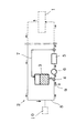
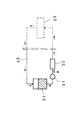
図1に示す第1実施例は、サニタリー機器等から成る製品製造装置(被洗浄機器)1に連結してこれをアルカリ洗浄液で、酸洗浄液で、もしくは清水で自動洗浄するための自動定置洗浄装置(CIP)2であって、図1に示す概略図のように、洗浄液タンク3から供給された洗浄液を切換バルブ等管路切換装置4を経て加熱装置5に供給して加熱し、この加熱した洗浄液を被洗浄機器1に供給して通過させると共にこの通過後の洗浄液を上記切換バルブ等管路切換装置4を経て加熱装置5に戻し用管路8を介して戻して当該洗浄液を、洗浄液タンク3からの洗浄液供給のストップ状態で循環ポンプ6により循環させることによって、所謂機器および配管(ライン)を一挙に洗浄する構成とすると共に戻し用管路8の途中に洗浄液の補充用装置10を連結してあるものである。勿論、図には示していないが温度センサーや濃度センサー等制御用機器を備えている。
【0011】
なお、図1において符号7で示す配管は、洗浄液タンク3を空にして清水(洗浄液でも可)で洗うのに用いるものであって、予め空の状態にした洗浄液タンク3に清水(水道水)を貯めてから当該清水を切換バルブ等管路切換装置4を経て加熱装置5に供給して加熱し、この加熱した清水を洗浄液タンク3に戻して循環ポンプ6により循環させることで洗浄液タンク3を洗浄するようにしてあるものである。
【0012】
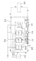
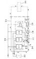
図2に示す第2実施例は、回収タンク11とアルカリ洗浄液タンク12と酸洗浄液タンク13と清水バランスタンク14等から成るタンクユニット部15と、多数個のサニタリオートバルブ群17と送液/循環ポンプ16等から成る送液ユニット部18と、熱交換器19と温度コントローラ20等から成る加熱ユニット部21と、上記タンクユニット部15に洗浄液(洗浄液)を供給する洗浄液供給ユニット部22と、を備えた自動定置洗浄装置(CIP)であって、タンクユニット部15から供給された洗浄液/清水を送液ユニット部18を経て加熱ユニット部21に供給して加熱し、この加熱した洗浄液/清水を被洗浄機器23に供給して通過させると共にこの通過後の洗浄液/清水を上記送液ユニット部18を経て加熱ユニット部21に戻して当該洗浄液/清水を、タンクユニット部15からの洗浄液供給のストップ状態で送液/循環ポンプ16により循環させる構成となっているものである。
【0013】
なお、図2において符号、26は循環する液の温度を計測する測温センサーであり、27は循環する液の濃度を計測する導電率による濃度計であり、28は回収タンク11、アルカリ洗浄液タンク12、酸洗浄液タンク13および清水バランスタンク14に清水を供給する清水供給管である。
【0014】
また、図1および図2において符号9および29はブロー管であって、清水すすぎ時に洗浄液/清水を排出するためのものである。
【0015】
上記第2実施例は、先ず、洗浄液供給ユニット部22からアルカリ洗浄液を供給してアルカリ洗浄液タンク12に、また洗浄液供給ユニット部22から酸洗浄液を供給して酸洗浄液タンク13に、更に清水供給管28から清水を供給して清水バランスタンク14にそれぞれ貯めてある状態として準備をする。この場合、回収タンク11には前回の洗浄作業で使用された清水で例えば、機器内および配管内にその洗浄後に残った水のような汚れていない水を、節水のために、この水でも充分役に立つときには適宜に再利用できるように貯めてある。
【0016】
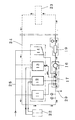
そして、上記の貯めたアルカリ洗浄液をサニタリオートバルブ群17および送液/循環ポンプ16を介して熱交換器19に送って加熱すると共に当該加熱したアルカリ洗浄液を、温度コントローラ20および測温センサー26で適温に保ちながら送液して被洗浄機器23内を通過させ、この通過した加熱アルカリ洗浄液をサニタリオートバルブ群17に戻し用管路24により戻して当該加熱アルカリ洗浄液を、アルカリ洗浄液タンク12からの供給をストップした状態で送液/循環ポンプ16により循環させ、よって被洗浄機器23を所謂アルカリ洗浄する。このアルカリ洗浄の完了後に清水供給によりアルカリ洗浄液を回収する。回収終了時のうすまり洗浄液を濃度計27で確認し、うすまりアルカリ洗浄液をブロー管29から排出する。
【0017】
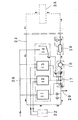
また、上記の貯めた酸洗浄液を上記アルカリ洗浄と同じように、サニタリオートバルブ群17および送液/循環ポンプ16を介して熱交換器19に送って加熱すると共に当該加熱した酸洗浄液を、温度コントローラ20および測温センサー26で適温に保ちながら送液して被洗浄機器23内を通過させ、この通過した加熱の酸洗浄液をサニタリオートバルブ群17に戻し用管路24により戻して当該加熱酸洗浄液を、酸洗浄液タンク13からの供給をストップした状態で送液/循環ポンプ16により循環させ、よって被洗浄機器23を所謂酸洗浄する。この酸洗浄の完了後に清水供給により酸洗浄液を回収する。回収終了時のうすまり洗浄液を濃度計27で確認し、うすまり酸洗浄液をブロー管29から排出する。
【0018】
また、上記の貯めた清水を上記アルカリ洗浄と同じように、サニタリオートバルブ群17および送液/循環ポンプ16を介して熱交換器19に送って加熱すると共に当該加熱した清水を、温度コントローラ20および測温センサー26で適温に保ちながら送液して被洗浄機器23内を通過させ、この通過した加熱の酸洗浄液をサニタリオートバルブ群17に戻し用管路24により戻して当該加熱清水を清水バランスタンク14からの供給をストップした状態で送液/循環ポンプ16により循環させ、よって被洗浄機器23を所謂清水洗浄する。機器内および配管内に残存している用済み清水を、この水でも充分役に立つときには適宜利用できるように回収タンク11に貯め、役に立たないようであればブロー管29から排出する。
【0019】
上記のアルカリ洗浄工程、酸洗浄工程、清水洗浄工程および回収工程は、通常、製品製造工程のあとに、清水洗浄工程→アルカリ洗浄工程→清水洗浄工程→酸洗浄工程→清水洗浄工程→回収工程の順で行って洗浄を完了するが、必ずしもこの順番でなくとも若しくは一部省略してもよい。
【0020】
【作用】
上記したような従来型(一般型)の洗浄装置は、洗浄液タンク内に残存する洗浄液の全ても設定温度まで加熱し、設定温度到達後一定時間の循環洗浄を行なう構成のもので、タンク内の液量を常に循環必要量(滞液量)以上にしてあるものであったために、結果として通常は必要滞液量以上を加熱していることになっていた。そこで、本発明は必要滞液量のみを加熱するようにしたことによって、無駄な加熱をなくして使用蒸気量を削減するようにしたものである。
【0021】
上記の洗浄液による洗浄後機器及び配管内面に付着した洗浄液を除去するために水道水、地下水、蒸留水等の清水を使用するが、本発明は、洗浄液タンク内まで洗浄しなくともよい場合にはこの洗浄液タンクに清水を循環させない状態で機器および管路を洗浄できるので、当該清水も上記の使用蒸気量と同じように削減できる。
【0022】
【発明の効果】
本発明によるときには、上記したようにタンクの中に残存する液を加熱しない状態で循環させる構成であるので、洗浄液、清水、加熱用蒸気の消費を削減でき、当該消費のコストを削減でき、環境汚染防止に不都合な用済み洗浄液の排出量を少なくすることができるものであって、初期の目的を充分に達成できるものである。
【0023】
また、上記のように異なる種類の洗浄液が収容される多数個の洗浄液タンクを並設し、これ等を順に使用して異なる種類の洗浄液による洗浄工程を行うようにしてあるので、機器および管路(ライン)を能率良く洗浄できる著効がある。
【0024】
更に、循環路もしくは戻し用路の途中から洗浄液を任意に補充可能としたので、汚れがひどい場合には循環する洗浄液の濃度を任意に高くして使用することもできるものであって、これによっても洗浄液消費量の削減が可能となる。
【図面の簡単な説明】
【図1】本発明の第1実施例を示す概念図である。
【図2】本発明の第2実施例を示す概念図である。
【図3】第2実施例でアルカリ洗浄をしている状態を示す説明図である。
【図4】第2実施例で酸洗浄をしている状態を示す説明図である。
【図5】第2実施例で清水洗浄をしている状態を示す説明図である。
【図6】第2実施例で回収水の再使用をしている状態を示す説明図である。
【図7】従来例を示す概念図である。
【符号の説明】
1 被洗浄機器
2 自動定置洗浄装置
3 洗浄液タンク
4 切換バルブ等管路切換装置
5 加熱装置
6 循環ポンプ
7 配管
8 戻し用管路
9 ブロー管
10 洗浄液の補充用装置
11 回収タンク
12 アルカリ洗浄液タンク
13 酸洗浄液タンク
14 清水バランスタンク
15 タンクユニット部
16 送液/循環ポンプ
17 サニタリオートバルブ
18 送液ユニット部
19 熱交換器
20 温度コントローラ
21 加熱ユニット部
22 洗浄液供給ユニット部
23 被洗浄機器
24 戻し用管路
26 測温センサー
27 濃度計
28 清水供給管
29 ブロー管
31 タンク
32 加熱装置
33 被洗浄機器
34 循環ポンプ
35 戻し用管路[0001]
[Industrial application fields]
The present invention relates to a cleaning method for cleaning a device to be cleaned such as a fluid product manufacturing apparatus, for automatic cleaning without disassembling the device / plant after product manufacture in the dairy industry, food, beverage, pharmaceutical industry, etc. The present invention relates to an automatic cleaning device (CIP) for a device to be cleaned.
[0002]
[Prior art]
This type of automatic in-situ cleaning device known in the art is composed of tanks, pumps, valves, heat exchangers, etc., pipes connecting them, various sensors for performing automatic control, control equipment, etc. And, for example, as shown in the schematic system diagram shown in FIG. 7, the pipe is used for cleaning a device to be cleaned such as a fluid product manufacturing apparatus every time the product manufacturing process is completed.
[0003]
Such a conventional automatic cleaning device (CIP), as is clear from FIG. 7, flows the cleaning liquid supplied from the outlet of the cleaning
[0004]
[Problems to be solved by the invention]
Since the automatic cleaning device described in the above prior art is configured to heat and circulate the liquid remaining in the tank, it consumes a large amount of cleaning liquid, a large amount of water, and heating steam. In other words, there are problems such as high cost and 3 large amount of used cleaning liquid that causes environmental pollution.
[0005]
An object of the present invention is to provide a novel cleaning method and an automatic cleaning apparatus of a type in which a device that sufficiently solves the above-described
[0006]
[Means for Solving the Problems]
In order to achieve the above object, the cleaning method according to the first aspect of the present invention is to heat the cleaning liquid supplied from the cleaning liquid tank with a heating device through a switching device such as a switching valve, and supply the heated cleaning liquid to the apparatus to be cleaned. passed through Te, passed through a washing solution after the pass conduit returning, by passage is supplied to the washing device and returned to the heating device via the switching valve such line switching device, the cleaning liquid, cleaning liquid When the cleaning liquid tank is circulated by a circulation pump in a state where the supply of the cleaning liquid from the tank is stopped and the cleaning liquid tank is cleaned, the cleaning liquid is stored in the cleaning liquid tank and then supplied to the heating device via a switching device such as a switching valve. that heating, the heated cleaning liquid is passed through a pipe for cleaning the solution tank, and wherein the Rukoto is circulated by a circulation pump back to the solution tank A.
[0007]
The cleaning method according to
[ 0008 ]
The stationary cleaning apparatus according to
[ 0009 ]
The stationary cleaning apparatus according to
[ 0010 ]
【Example】
The first embodiment shown in FIG. 1 is connected to a product manufacturing apparatus (device to be cleaned) 1 composed of a sanitary device or the like, and an automatic stationary cleaning device for automatically cleaning the product with an alkaline cleaning solution, an acid cleaning solution, or fresh water. (CIP) 2, as shown in the schematic diagram of FIG. 1, the cleaning liquid supplied from the
[ 0011 ]
1 is used to empty the cleaning
[ 0012 ]
The second embodiment shown in FIG. 2 is a tank unit portion 15 comprising a
[ 0013 ]
In FIG. 2, reference numeral 26 denotes a temperature measuring sensor for measuring the temperature of the circulating liquid, 27 denotes a concentration meter based on conductivity for measuring the concentration of the circulating liquid, and 28 denotes a
[ 0014 ]
In FIGS. 1 and 2,
[ 0015 ]
In the second embodiment, first, an alkaline cleaning liquid is supplied from the cleaning
[ 0016 ]
The stored alkaline cleaning liquid is sent to the
[ 0017 ]
Further, the stored acid cleaning liquid is sent to the
[ 0018 ]
Further, the stored fresh water is heated by being sent to the
[ 0019 ]
The above alkali cleaning process, acid cleaning process, fresh water cleaning process and recovery process are usually performed after the product manufacturing process, as follows: fresh water cleaning process-> alkali cleaning process-> fresh water cleaning process-> acid cleaning process-> fresh water cleaning process-> recovery process The cleaning is performed in order, but the cleaning is not necessarily performed in this order or a part of the cleaning may be omitted.
[ 0020 ]
[Action]
The conventional (general) cleaning apparatus as described above is configured to heat all of the cleaning liquid remaining in the cleaning liquid tank to the set temperature and perform circulating cleaning for a certain time after reaching the set temperature. Since the amount of liquid was always set to the amount necessary for circulation (the amount of liquid stagnant), as a result, the amount of liquid necessary for the amount of liquid stagnated was normally heated. Therefore, in the present invention, only the necessary amount of stagnant liquid is heated, so that useless heating is eliminated and the amount of steam used is reduced.
[ 0021 ]
In order to remove the cleaning liquid adhering to the equipment and piping inner surface after cleaning with the above cleaning liquid, tap water, ground water, distilled water, etc. are used, but the present invention is not required to clean the cleaning liquid tank. Since the equipment and the pipe line can be washed without circulating the fresh water to the washing liquid tank, the fresh water can be reduced in the same manner as the above-mentioned used steam amount.
[ 0022 ]
【The invention's effect】
According to the present invention, as described above, since the liquid remaining in the tank is circulated without being heated, consumption of the cleaning liquid, fresh water, and heating steam can be reduced, and the cost of the consumption can be reduced. It is possible to reduce the discharge amount of used cleaning liquid which is inconvenient for preventing contamination, and can sufficiently achieve the initial purpose.
[ 0023 ]
Also, as described above, a large number of cleaning liquid tanks containing different types of cleaning liquids are arranged side by side, and these are used in order to perform a cleaning process using different types of cleaning liquids. (Line) can be cleaned efficiently.
[ 0024 ]
Furthermore, since the cleaning liquid can be replenished arbitrarily from the middle of the circulation path or the return path, the concentration of the circulating cleaning liquid can be arbitrarily increased when the dirt is severe. In addition, the consumption of cleaning liquid can be reduced.
[Brief description of the drawings]
FIG. 1 is a conceptual diagram showing a first embodiment of the present invention.
FIG. 2 is a conceptual diagram showing a second embodiment of the present invention.
FIG. 3 is an explanatory diagram showing a state where alkali cleaning is performed in the second embodiment.
FIG. 4 is an explanatory view showing a state where acid cleaning is performed in the second embodiment.
FIG. 5 is an explanatory view showing a state in which clean water cleaning is performed in the second embodiment.
FIG. 6 is an explanatory view showing a state in which recovered water is reused in the second embodiment.
FIG. 7 is a conceptual diagram showing a conventional example.
[Explanation of symbols]
DESCRIPTION OF
Claims (4)
洗浄液タンクを洗浄する場合には、洗浄液タンクに洗浄液を貯めてから当該洗浄液を切換バルブ等管路切換装置を経て加熱装置に供給して加熱し、この加熱した洗浄液を上記洗浄液タンクを洗浄するための配管に通過させ、洗浄液タンクに戻して循環ポンプにより循環させることを特徴とする流体製品製造装置等の被洗浄機器を洗浄する洗浄方法。The cleaning liquid supplied from the cleaning liquid tank is heated by the heating device through the switching valve and the like conduit switching apparatus, the heating washings were passed is supplied to the cleaning device, passes through a washing solution after the pass conduit returning The cleaning liquid is circulated by a circulation pump in a stop state of the supply of the cleaning liquid from the cleaning liquid tank by passing it back to the heating device through the switching device such as the switching valve and supplying it to the apparatus to be cleaned .
When cleaning the cleaning liquid tank, the cleaning liquid is stored in the cleaning liquid tank, and then the cleaning liquid is supplied to the heating device via the switching device such as a switching valve and heated, and the heated cleaning liquid is used to clean the cleaning liquid tank. cleaning method of piping is passed through, washing the object to be cleaned equipment of the fluid product manufacturing apparatus according to claim Rukoto is circulated by a circulation pump back into the solution tank.
洗浄液タンクに洗浄液を貯めてから切換バルブ等管路切換装置を経て加熱装置に供給して加熱した当該洗浄液を洗浄液タンクに戻して循環ポンプにより循環させる洗浄液タンクを洗浄するための配管とから成ることを特徴とする定置洗浄装置。A cleaning liquid tank, a heating device with a temperature controller that heats the cleaning liquid supplied from the cleaning liquid tank via a switching device such as a switching valve and supplies the cleaning liquid to the apparatus to be cleaned, and the cleaning liquid after passing through the apparatus to be cleaned A return pipe for circulating the cleaning liquid through a circulation pump in a stop state of the supply of the cleaning liquid from the cleaning liquid tank by returning to the heating device via a switching apparatus such as a switching valve;
It consists of piping for cleaning the cleaning liquid tank that stores the cleaning liquid in the cleaning liquid tank and then supplies the heated cleaning liquid to the heating device via a switching device such as a switching valve and returns it to the cleaning liquid tank and circulates it with a circulation pump. A stationary cleaning device characterized by
Priority Applications (1)
| Application Number | Priority Date | Filing Date | Title |
|---|---|---|---|
| JP2001294257A JP4050488B2 (en) | 2001-09-26 | 2001-09-26 | Cleaning method for cleaning apparatus to be cleaned such as fluid product manufacturing apparatus and automatic cleaning apparatus for the apparatus |
Applications Claiming Priority (1)
| Application Number | Priority Date | Filing Date | Title |
|---|---|---|---|
| JP2001294257A JP4050488B2 (en) | 2001-09-26 | 2001-09-26 | Cleaning method for cleaning apparatus to be cleaned such as fluid product manufacturing apparatus and automatic cleaning apparatus for the apparatus |
Publications (2)
| Publication Number | Publication Date |
|---|---|
| JP2003093992A JP2003093992A (en) | 2003-04-02 |
| JP4050488B2 true JP4050488B2 (en) | 2008-02-20 |
Family
ID=19115896
Family Applications (1)
| Application Number | Title | Priority Date | Filing Date |
|---|---|---|---|
| JP2001294257A Expired - Fee Related JP4050488B2 (en) | 2001-09-26 | 2001-09-26 | Cleaning method for cleaning apparatus to be cleaned such as fluid product manufacturing apparatus and automatic cleaning apparatus for the apparatus |
Country Status (1)
| Country | Link |
|---|---|
| JP (1) | JP4050488B2 (en) |
Families Citing this family (9)
| Publication number | Priority date | Publication date | Assignee | Title |
|---|---|---|---|---|
| US8398781B2 (en) * | 2004-08-27 | 2013-03-19 | Ecolab Usa Inc. | Methods for cleaning industrial equipment with pre-treatment |
| CN100425357C (en) * | 2005-03-23 | 2008-10-15 | 宁波市鑫洋电器有限公司 | Heating device for steam cleaning machine |
| KR101173395B1 (en) | 2009-05-28 | 2012-08-10 | 웅진코웨이주식회사 | Washing device for water treatment apparatus |
| JP2013111537A (en) * | 2011-11-29 | 2013-06-10 | Kurita Water Ind Ltd | Method and device for cleaning equipment |
| DE102015119318A1 (en) * | 2015-11-10 | 2017-05-11 | Krones Ag | Device for cleaning a part of a beverage filling plant to be cleaned |
| CN108160584B (en) * | 2018-01-29 | 2023-12-12 | 爱咕噜(上海)智能科技有限公司 | Cleaning pump trucks and corresponding cleaning methods |
| CN111214857A (en) * | 2020-03-27 | 2020-06-02 | 江苏中有信科技有限公司 | A kind of alcohol precipitation tank online cleaning device |
| WO2022099346A1 (en) * | 2020-11-10 | 2022-05-19 | Ecochem Australia Pty Ltd | Systems and methods for automatically cleaning converters with heated fluids |
| CN115159602B (en) * | 2022-07-14 | 2023-12-05 | 天津国投津能发电有限公司 | Low-temperature multi-effect seawater desalination cleaning sludge on-line removal system |
-
2001
- 2001-09-26 JP JP2001294257A patent/JP4050488B2/en not_active Expired - Fee Related
Also Published As
| Publication number | Publication date |
|---|---|
| JP2003093992A (en) | 2003-04-02 |
Similar Documents
| Publication | Publication Date | Title |
|---|---|---|
| CN101543390B (en) | Heat reclaim device with self-cleaning | |
| US9592311B2 (en) | Washing machine and corresponding washing method | |
| JP4050488B2 (en) | Cleaning method for cleaning apparatus to be cleaned such as fluid product manufacturing apparatus and automatic cleaning apparatus for the apparatus | |
| US12389870B2 (en) | CIP system | |
| CN117019782A (en) | Device for cleaning a facility part to be cleaned for beverage filling applications | |
| CN106415182A (en) | An apparatus for recovering heat from a liquid flowing out of an industrial plant | |
| FI105659B (en) | Apparatus for cleaning one or more parts of a food processing plant | |
| CN113145585B (en) | Cleaning device of pot matching machine | |
| JPH0649520B2 (en) | Beverage filling line cleaning device | |
| JP7070628B2 (en) | Cleaning and sterilization method of aseptic filling machine and aseptic filling machine | |
| Stewart et al. | Clean in place | |
| CN217314939U (en) | CPI cleaning system suitable for pharmaceutical industry | |
| Seiberling et al. | Engineering considerations for CIP/SIP systems | |
| US20090277477A1 (en) | Multitank conveyor-type dishwasher and an operating method for it | |
| CN210936180U (en) | UHT positive and negative belt cleaning device | |
| US20060054566A1 (en) | System and method for reducing deionized water consumption | |
| CN223126308U (en) | A water dispenser with self-cleaning function | |
| RU2747656C2 (en) | Beverage making device | |
| JPH06133929A (en) | Device for washing and disinfecting endoscope | |
| CN108651687B (en) | Self-service ice cream machine | |
| JP2022102465A (en) | Cleaning and sterilization method of carbon dioxide line of aseptic filling machine and aseptic filling machine | |
| CN107354474B (en) | A kind of multifunctional mobile chemical cleaning vehicle suitable for industrial equipment heat exchanger | |
| CN218636413U (en) | Corrosion-resistant centralized liquid supply equipment with automatic stirring function | |
| JP3457756B2 (en) | Cleaning device output flow control device | |
| JP2025097392A (en) | Liquid supply device and liquid supply method |
Legal Events
| Date | Code | Title | Description |
|---|---|---|---|
| A621 | Written request for application examination |
Free format text: JAPANESE INTERMEDIATE CODE: A621 Effective date: 20040701 |
|
| A131 | Notification of reasons for refusal |
Free format text: JAPANESE INTERMEDIATE CODE: A131 Effective date: 20070710 |
|
| A521 | Written amendment |
Free format text: JAPANESE INTERMEDIATE CODE: A523 Effective date: 20070910 |
|
| TRDD | Decision of grant or rejection written | ||
| A01 | Written decision to grant a patent or to grant a registration (utility model) |
Free format text: JAPANESE INTERMEDIATE CODE: A01 Effective date: 20071030 |
|
| A61 | First payment of annual fees (during grant procedure) |
Free format text: JAPANESE INTERMEDIATE CODE: A61 Effective date: 20071129 |
|
| R150 | Certificate of patent or registration of utility model |
Free format text: JAPANESE INTERMEDIATE CODE: R150 |
|
| FPAY | Renewal fee payment (event date is renewal date of database) |
Free format text: PAYMENT UNTIL: 20101207 Year of fee payment: 3 |
|
| FPAY | Renewal fee payment (event date is renewal date of database) |
Free format text: PAYMENT UNTIL: 20101207 Year of fee payment: 3 |
|
| FPAY | Renewal fee payment (event date is renewal date of database) |
Free format text: PAYMENT UNTIL: 20111207 Year of fee payment: 4 |
|
| FPAY | Renewal fee payment (event date is renewal date of database) |
Free format text: PAYMENT UNTIL: 20121207 Year of fee payment: 5 |
|
| FPAY | Renewal fee payment (event date is renewal date of database) |
Free format text: PAYMENT UNTIL: 20131207 Year of fee payment: 6 |
|
| R250 | Receipt of annual fees |
Free format text: JAPANESE INTERMEDIATE CODE: R250 |
|
| R250 | Receipt of annual fees |
Free format text: JAPANESE INTERMEDIATE CODE: R250 |
|
| R250 | Receipt of annual fees |
Free format text: JAPANESE INTERMEDIATE CODE: R250 |
|
| R250 | Receipt of annual fees |
Free format text: JAPANESE INTERMEDIATE CODE: R250 |
|
| LAPS | Cancellation because of no payment of annual fees |