JP4049565B2 - Low noise MRI scanner - Google Patents
Low noise MRI scanner Download PDFInfo
- Publication number
- JP4049565B2 JP4049565B2 JP2001304782A JP2001304782A JP4049565B2 JP 4049565 B2 JP4049565 B2 JP 4049565B2 JP 2001304782 A JP2001304782 A JP 2001304782A JP 2001304782 A JP2001304782 A JP 2001304782A JP 4049565 B2 JP4049565 B2 JP 4049565B2
- Authority
- JP
- Japan
- Prior art keywords
- magnet
- assembly
- coil assembly
- gradient
- patient
- Prior art date
- Legal status (The legal status is an assumption and is not a legal conclusion. Google has not performed a legal analysis and makes no representation as to the accuracy of the status listed.)
- Expired - Lifetime
Links
- 238000003384 imaging method Methods 0.000 claims description 48
- 230000005534 acoustic noise Effects 0.000 claims description 43
- 239000004020 conductor Substances 0.000 claims description 30
- 239000000463 material Substances 0.000 claims description 24
- 238000002955 isolation Methods 0.000 claims description 21
- 230000005540 biological transmission Effects 0.000 claims description 16
- 239000000725 suspension Substances 0.000 claims description 14
- 230000003068 static effect Effects 0.000 claims description 8
- 230000005284 excitation Effects 0.000 claims description 6
- 238000002595 magnetic resonance imaging Methods 0.000 description 24
- 239000002184 metal Substances 0.000 description 11
- 229910052751 metal Inorganic materials 0.000 description 11
- 239000011152 fibreglass Substances 0.000 description 10
- 230000000712 assembly Effects 0.000 description 8
- 238000000429 assembly Methods 0.000 description 8
- 229920001971 elastomer Polymers 0.000 description 8
- 239000005060 rubber Substances 0.000 description 7
- 229910000831 Steel Inorganic materials 0.000 description 6
- 238000000034 method Methods 0.000 description 6
- 239000010959 steel Substances 0.000 description 6
- 239000012811 non-conductive material Substances 0.000 description 5
- 239000011358 absorbing material Substances 0.000 description 4
- 230000033001 locomotion Effects 0.000 description 4
- 239000004593 Epoxy Substances 0.000 description 3
- 239000003990 capacitor Substances 0.000 description 3
- 238000013016 damping Methods 0.000 description 3
- 238000013461 design Methods 0.000 description 3
- 238000010586 diagram Methods 0.000 description 3
- 239000001307 helium Substances 0.000 description 3
- 229910052734 helium Inorganic materials 0.000 description 3
- SWQJXJOGLNCZEY-UHFFFAOYSA-N helium atom Chemical compound [He] SWQJXJOGLNCZEY-UHFFFAOYSA-N 0.000 description 3
- 238000004804 winding Methods 0.000 description 3
- XEEYBQQBJWHFJM-UHFFFAOYSA-N Iron Chemical compound [Fe] XEEYBQQBJWHFJM-UHFFFAOYSA-N 0.000 description 2
- 239000012814 acoustic material Substances 0.000 description 2
- 239000006260 foam Substances 0.000 description 2
- 239000007789 gas Substances 0.000 description 2
- 239000007788 liquid Substances 0.000 description 2
- 229910001220 stainless steel Inorganic materials 0.000 description 2
- 239000010935 stainless steel Substances 0.000 description 2
- XLYOFNOQVPJJNP-UHFFFAOYSA-N water Substances O XLYOFNOQVPJJNP-UHFFFAOYSA-N 0.000 description 2
- 229920000049 Carbon (fiber) Polymers 0.000 description 1
- 229920000459 Nitrile rubber Polymers 0.000 description 1
- 239000004698 Polyethylene Substances 0.000 description 1
- 238000010521 absorption reaction Methods 0.000 description 1
- 230000002238 attenuated effect Effects 0.000 description 1
- 239000004917 carbon fiber Substances 0.000 description 1
- 238000004891 communication Methods 0.000 description 1
- 229920001940 conductive polymer Polymers 0.000 description 1
- 238000001816 cooling Methods 0.000 description 1
- 230000000694 effects Effects 0.000 description 1
- 239000000806 elastomer Substances 0.000 description 1
- 239000012777 electrically insulating material Substances 0.000 description 1
- 230000014509 gene expression Effects 0.000 description 1
- 239000003365 glass fiber Substances 0.000 description 1
- 125000004435 hydrogen atom Chemical group [H]* 0.000 description 1
- 229910052742 iron Inorganic materials 0.000 description 1
- 239000000696 magnetic material Substances 0.000 description 1
- 230000005415 magnetization Effects 0.000 description 1
- 238000004519 manufacturing process Methods 0.000 description 1
- 238000005259 measurement Methods 0.000 description 1
- 230000009347 mechanical transmission Effects 0.000 description 1
- VNWKTOKETHGBQD-UHFFFAOYSA-N methane Chemical compound C VNWKTOKETHGBQD-UHFFFAOYSA-N 0.000 description 1
- 239000000203 mixture Substances 0.000 description 1
- 238000012986 modification Methods 0.000 description 1
- 230000004048 modification Effects 0.000 description 1
- 238000001208 nuclear magnetic resonance pulse sequence Methods 0.000 description 1
- -1 polyethylene Polymers 0.000 description 1
- 229920000573 polyethylene Polymers 0.000 description 1
- 239000000843 powder Substances 0.000 description 1
- 230000001902 propagating effect Effects 0.000 description 1
- 238000007789 sealing Methods 0.000 description 1
- 238000000926 separation method Methods 0.000 description 1
- 125000006850 spacer group Chemical group 0.000 description 1
- 238000001356 surgical procedure Methods 0.000 description 1
- 230000036962 time dependent Effects 0.000 description 1
Images


Classifications
-
- G—PHYSICS
- G01—MEASURING; TESTING
- G01R—MEASURING ELECTRIC VARIABLES; MEASURING MAGNETIC VARIABLES
- G01R33/00—Arrangements or instruments for measuring magnetic variables
- G01R33/20—Arrangements or instruments for measuring magnetic variables involving magnetic resonance
- G01R33/28—Details of apparatus provided for in groups G01R33/44 - G01R33/64
- G01R33/38—Systems for generation, homogenisation or stabilisation of the main or gradient magnetic field
- G01R33/385—Systems for generation, homogenisation or stabilisation of the main or gradient magnetic field using gradient magnetic field coils
- G01R33/3854—Systems for generation, homogenisation or stabilisation of the main or gradient magnetic field using gradient magnetic field coils means for active and/or passive vibration damping or acoustical noise suppression in gradient magnet coil systems
-
- A—HUMAN NECESSITIES
- A61—MEDICAL OR VETERINARY SCIENCE; HYGIENE
- A61B—DIAGNOSIS; SURGERY; IDENTIFICATION
- A61B5/00—Measuring for diagnostic purposes; Identification of persons
- A61B5/05—Detecting, measuring or recording for diagnosis by means of electric currents or magnetic fields; Measuring using microwaves or radio waves
- A61B5/055—Detecting, measuring or recording for diagnosis by means of electric currents or magnetic fields; Measuring using microwaves or radio waves involving electronic [EMR] or nuclear [NMR] magnetic resonance, e.g. magnetic resonance imaging
Landscapes
- Physics & Mathematics (AREA)
- Health & Medical Sciences (AREA)
- Life Sciences & Earth Sciences (AREA)
- Condensed Matter Physics & Semiconductors (AREA)
- General Physics & Mathematics (AREA)
- Nuclear Medicine, Radiotherapy & Molecular Imaging (AREA)
- Engineering & Computer Science (AREA)
- Medical Informatics (AREA)
- Biophysics (AREA)
- Pathology (AREA)
- High Energy & Nuclear Physics (AREA)
- Biomedical Technology (AREA)
- Heart & Thoracic Surgery (AREA)
- Radiology & Medical Imaging (AREA)
- Molecular Biology (AREA)
- Surgery (AREA)
- Animal Behavior & Ethology (AREA)
- General Health & Medical Sciences (AREA)
- Public Health (AREA)
- Veterinary Medicine (AREA)
- Magnetic Resonance Imaging Apparatus (AREA)
Description
【0001】
【発明の背景】
本発明は、全般的には、磁気共鳴イメージング(MRI)スキャナに関し、さらに詳細には、低ノイズ型MRIスキャナに関する。
【0002】
MRIスキャナは、医学的診断など様々な分野で使用されており、典型的には、マグネットの動作に基づいて画像生成するためのコンピュータ、傾斜コイル・アセンブリ、及び高周波コイルを使用している。このマグネットは原子核(例えば、水素原子の原子核)を高周波励起に対して反応させている均一な主磁場を発生させる。傾斜コイル・アセンブリはこの主磁場上に一連のパルス状の空間傾斜磁場を付加し、これによりイメージング・ボリューム内の各点に対して、イメージング・パルス・シーケンス中の磁場の一意の組に対応した空間的個別性を与えている。この高周波コイルは、高周波コイルにより検出されかつ画像生成のためのコンピュータにより使用される振動する横方向磁化を一時的に生成するための励起周波数パルスを発生させている。典型的には、マグネット内には高周波コイルと傾斜コイル・アセンブリとが存在する。
【0003】
MRIスキャナ用のマグネットとしては、超伝導コイル・マグネット、抵抗性コイル・マグネット、永久磁石が含まれる。周知の超伝導マグネットとしては、液体ヘリウム冷却式の超伝導マグネットやクライオクーラ冷却式の超伝導マグネットが含まれる。周知の超伝導マグネット設計としては、円筒状マグネットや開放マグネットが含まれる。
【0004】
円筒状マグネットは、典型的には、円筒状に成形されており、軸方向に向いた静磁場を有する。円筒状マグネットに基づくMRIシステムでは、高周波コイル、傾斜コイル・アセンブリ及びそのマグネットは、形状が概して円環状で円筒状であり、かつ概して共軸に整列しており、その傾斜コイル・アセンブリは高周波コイルの外周を囲繞すると共にそのマグネットは傾斜コイル・アセンブリの外周を囲繞している。
【0005】
開放マグネットは、典型的には、間隔をおいた2つのマグネット・アセンブリを利用しており、このアセンブリ間の間隔により医療スタッフはMRI撮影中に手術その他の医学的処置をするためのアクセスが可能となる。空間が開放されているため、円筒状のマグネット設計で起こることがあるような閉鎖恐怖の感情を患者が克服するのに役立つ。
【0006】
一般に、MRIスキャナの様々な構成要素は、撮影している患者やスキャナのユーザにとって不快と感ずる可能性があるような音響ノイズの発生源や伝搬路になる。例えば、MRIスキャナの傾斜コイル・アセンブリは多くの患者が不快と感ずるような大きな音響ノイズを発生させる。これらの音響ノイズはスキャナの患者ボアの内部だけでなく、スキャナの外部でも生じている。傾斜コイル・アセンブリのノイズを低減させるためには、ノイズ排除用患者イヤホンなどの能動的なノイズ制御技法が用いられてきた。周知の受動的ノイズ制御技法としては、傾斜コイル・アセンブリを真空エンクロージャ内に位置させることが含まれる。
【0007】
RFコイル構造体も、振動や音響ノイズのまた別の発生源となる。MRIシステムでは、電気的に励起した傾斜コイルを利用して時間変化する磁場を主磁場上、すなわちB0磁場上に付加している。これらの時間変化する磁場はRFコイルの導体内にうず電流を誘導する傾向があり、これによりRFコイルの機械的動きが生ずることがある。
【0008】
音響ノイズのさらに別の発生源及び伝搬路は、スキャナ内の機械的構成要素の振動によるものである。機械技術分野では、隔絶マウントにより支持された機械類からの振動がその隔絶マウントを支持している周辺構造に伝達しないように隔絶マウントを設計し使用することは周知である。従来の隔絶マウントとしては、エラストマ・タイプのマウントやバネ・タイプのマウントが含まれる。こうした隔絶マウントは、熟練者によって、マウントと機械類の振動の固有振動数がその機械類の重要な励起周波数未満となるように設計して有効な振動隔絶を提供している。
【0009】
MRIスキャナ内の様々な構成要素による音響ノイズを低下させるためのこうした技法や措置は一部では有効となっているが、患者や手技者は未だに、MRIスキャナ内やその周辺のノイズが問題であると感じている。スキャナ内やその周辺の音響ノイズの複数の発生源や伝搬路に対処しているノイズを低下させたMRIスキャナが必要とされている。
【0010】
【発明の要約】
被検体の磁気共鳴(MR)画像を作成すると共に撮影中に発生する音響ノイズを実質的に最小にするための低ノイズ型イメージング装置を提供する。本イメージング装置は、マグネット・アセンブリと、傾斜コイル・アセンブリと、RFコイル・アセンブリとを備えており、このマグネット・アセンブリ、傾斜コイル・アセンブリ及びRFコイル・アセンブリのうちの少なくとも1つはイメージング装置内やその周辺での音響ノイズの発生及び伝達を減少させるように構成されている。
【0011】
磁気共鳴イメージング(MRI)システム用の高周波(RF)コイル・アセンブリは、その各々が高周波パルスを送信し、被検体内で誘導されるMR信号を受信し、かつイメージング装置内やその周辺での音響ノイズの要因となるうず電流励起を低下させるような幅を有している複数の導体を備えている。さらに、この複数の導体と患者ボアチューブの間には音響吸収材料からなる層を配置することができる。
【0012】
磁気共鳴イメージング(MRI)システムのためのイメージング装置用のマグネット・アセンブリは、外側表面と、この外側表面にマグネットを取り付けるための複数の懸架部材と、を備えている。この懸架部材は音響ノイズの発生及び伝達を低下させるように構成する。
【0013】
本発明の特徴及び利点は、添付の図面と共に以下の本発明の詳細な説明を読めば明らかとなろう。
【0014】
【発明の実施の形態】
図1、2及び3を参照すると、本発明の実施形態を適用できる例示的なイメージング装置を表している。このイメージング装置は患者または被検体の磁気共鳴(MR)画像を作成するのに有用なタイプのものである。図面の全体を通じて、同じ番号は一貫して同じ要素を意味している。図1、2及び3は、円筒状の超伝導マグネットに基づくMRシステムを示している。当業者であれば、同様の構成要素に関する機能及び説明を開放マグネット構成で使用するように開放マグネット型MRシステムに適用可能できることを理解するであろう。
【0015】
図2を参照すると、MRイメージングに関して通常用いられるタイプのマグネット配置の断面図を示している。マグネット・アセンブリは、形状が概して円筒状で円環状であると共に、マグネット常温ボア4と呼ぶ内側表面と、パッシブ・マグネット・シム5(同様に、図1に示す)と、マグネット容器6と、クライオスタット・シェル7とを、外側表面の周囲で放射状に配置して備えている。マグネット・アセンブリはさらに、懸架部材13とエンドキャップ・シール20を備えている(これについては、後でより詳細に説明する)。
【0016】
典型的には、マグネット容器6は超伝導マグネット(図示せず)を囲繞しており、この超伝導マグネットは、よく知られるように、その各々が同じ方向に大きな同一電流を流すことができるような放射方向に整列させ長手方向に離間させた幾つかの超伝導主コイルを含んでいる。さらに、この超伝導主コイルは、撮影しようとする被検体を配置するマグネットのボア内の中心に位置させる球状のイメージング・ボリューム範囲で高い均一性をもつ磁場を発生させるように設計されている。超伝導主コイルは、典型的には0.5T〜8Tの範囲にある、B0として知られる主静磁場を発生させる。超伝導主コイルはマグネット容器6により囲繞されている。マグネット容器6は一般に、マグネットの巻き線を周知の方式で封入しかつ冷却するためのヘリウム容器及び熱シールドまたは低温シールドを含んでいる。さらに、マグネット容器6により、熱が超伝導マグネットに伝達されるのを防止している。以下において、本明細書で記載する超伝導主コイルや、従来の熱シールド、液体ヘリウムのデュワーその他は、一般にマグネット容器6により示しており、分かりやすくするためこれらは図面から省略している。クライオスタット・シェル7はマグネット・アセンブリの外側表面を覆っている。クライオスタット・シェル7は一般に金属製であり、典型的には鋼鉄またはステンレス鋼製である。
【0017】
さらに図2を参照すると、RFコイル・アセンブリ2、傾斜コイル・アセンブリ3及びマグネット・アセンブリは、その形状が概して円環状で円筒状であり、かつ概して共軸に整列しており、傾斜コイル・アセンブリは高周波コイルの外周を囲繞すると共にマグネットは傾斜コイル・アセンブリの外周を囲繞している。図1を参照すると、側面図によりイメージング装置の構成要素の各々の相対的配置を表している。患者または撮影する被検体200(図示せず、図3を参照)は、患者ボアチューブ1により囲繞される円筒状のイメージング・ボリューム101内に位置決めされる。患者または被検体200は患者寝台上またはクレードル104(図示せず、図3を参照)上で中心軸103に沿ってイメージング装置内に挿入される。中心軸103は、マグネット・アセンブリの軸に沿ってB0磁場の方向と平行に整列させる。ボアチューブ1は、FRP(ガラス繊維強化プラスチック)など導電性が低いか不導体の材料で製作することが望ましい。この実施形態では、RFコイル・アセンブリ2は、従来の鳥かご形RFコイル配置などにより患者ボアチューブ1の外側表面上に取り付けられており、例えば均一な高周波(RF)磁場を維持するために患者ボアチューブの外側表面に沿って複数の導体や容量性素子を互いに離間して配置している。RFコイル・アセンブリ2を用いることにより、MRイメージングの分野でよく知られるように、患者または被検体200に対して高周波磁場パルスを印加し、かつ被検体200から戻されるMRI情報を受け取っている。傾斜コイル・アセンブリ3は、その周囲で離間させた共軸の関係で配置させ、周知の方式により時刻依存の傾斜磁場パルスを発生させている。傾斜コイル・アセンブリ3の周囲には放射状に、常温ボア4、マグネット容器6及びクライオスタット・シェル7を含むマグネット・アセンブリが配置され、これにより上述したように、MRI画像の作成に必要な静磁場を生成している。
【0018】
さらに図1を参照すると、常温ボア4により一般にマグネット・アセンブリの円柱状の内側表面を示している。このマグネット常温ボアは、典型的には金属製である。常温ボア4の円柱状の内表面上にはパッシブ・マグネット・シム5がある。このシム5は静磁場に対する微小な調整を行うために、よく知られた方法で使用される。このシムは、典型的には薄肉の鉄製または鋼鉄製のストリップである。
【0019】
さらに図1を参照すると、イメージング装置はさらに、イメージング装置の構成要素を囲繞するような一対のエンドキャップ12を備えている。エンドキャップ12は、患者ボアチューブ1の端部部分をマグネット・アセンブリに固定可能に装着させることにより患者ボアチューブ1を適所に保持している。エンドキャップ・シール20は、エンドキャップ12と患者ボアチューブ1の間の気密シールの役割を果たしており、さらに傾斜コイル・アセンブリ3を囲繞するための真空スペース11を維持している。エンドキャップ・シール20は、典型的には、真空スペース11内で所望の真空を維持するために3/4〜1インチの厚さを有する適合したガスケット材料より製作される。エンドキャップ・シール20は、マグネットのクライオスタット・シェル7とエンドキャップ12の間で振動を隔絶できるようにその弾性特性が選択される。
【0020】
図3を参照すると、イメージング装置の構成要素はさらに、被検体200をイメージング・ボリューム101内に挿入しかつ位置決めするための、患者寝台やクレードル104などの支持構造を含む。患者クレードル104は、ローラーを用いるなど周知の方式によりブリッジ102に沿って摺動可能である。ブリッジ102は前方ブリッジ支持体105及び後方ブリッジ支持体106により支持されている。各ブリッジ支持体は、床面またはマグネット・アセンブリに固定される。さらに、クレードルの電子回路ユニットは、患者クレードル104の動きを制御するためにブリッジ102またはクレードル104に結合させている。
【0021】
傾斜コイル・アセンブリ3は、一般に、1)傾斜コイルに作用するローレンツ(電磁的)力による振動と、2)傾斜コイル・アセンブリと接触していない導電性部品内のローレンツ力によるノイズ、というMRイメージング・システム内の2つの音響ノイズ源の要因になっている。傾斜コイル・アセンブリ3は傾斜巻き線を備えており、この巻き線は典型的には、所望の傾斜磁場を発生させる形状に成形したワイヤまたは扁平な導電性ストリップである。傾斜巻き線のワイヤは強い磁場内にあり、
【0022】
【外1】

さらに、ワイヤ内の電流は、典型的には、数百アンペア程度と大きく、また静磁場は典型的には0.5T〜8Tの範囲となることがある。したがって、このローレンツ力は極めて大きくなり、傾斜アセンブリにかなりの振動を生じさせることがある。また一方こうした振動は空気を変位させて耳に聞こえる音を発生させることがある。さらに、この傾斜アセンブリの振動は、マグネット系の構造体を通って機械的に伝達されことがあり、またこの振動により構造体内の別の部品に振動を起こさせ、引き続き音を発生させることがある。音響ノイズの第2の発生源は、傾斜アセンブリと接触していない導電性部品内のローレンツ力によるものである。こうした力が生じる理由は、例えば、傾斜磁場のパルス状磁場によりMRIシステムの様々な導電性部品内にうず電流が誘導され、さらにこれらのうず電
【0024】
【外2】
RFコイル・アセンブリもまた、MRイメージング・システム内の音響ノイズの発生源である。RFコイル・アセンブリ2は、典型的には、鳥かご形構成で装着された大容積のRFコイルであり、導体のエッチングしたパターンを使用して製作される。さらに、これらの導体は、典型的には、幅が数インチとなることがある。大容積RFコイルは、典型的には、患者ボアの長さの約半分であって、患者ボアチューブ1の円周全体に巻かれており、さらに、患者ボアチューブ1にしっかりと装着されている。しかし、この大容積RFコイルは、傾斜アセンブリ3からのパルス状の傾斜磁場の影響を受ける。これらのパルス状磁場により大容積RFコイルの導体内にうず電流が誘導されると共に、このうず電流は静磁場と協
【0026】
【外3】
![]()
レンツ力を発生させる。次いで、これらの振動は患者やシステムのオペレータに聞こえるような音響ノイズを発生させる。
【0028】
被検体のMR画像を作成するためのイメージング装置の実施の一形態では、そのイメージング装置は、傾斜コイル・アセンブリと、RFコイル・アセンブリと、マグネット・アセンブリとを備えており、これらのアセンブリの各々は、撮影中におけるイメージング装置内やその周辺での音響ノイズの発生及び伝達を減少させるように選択的に構成されている。傾斜アセンブリ、RFコイル・アセンブリ、マグネット・アセンブリ、並びにMRIシステムのその他の構成要素の各々は音響ノイズの発生源や伝搬路の一因となる。これらのアセンブリの各々で音響ノイズを低下させるための実施形態を提示することにする。具体的な用途においては、これらのアセンブリや構成要素に関する各実施形態の特徴を組み合わせてイメージング装置の音響ノイズを低下させることができることを理解されたい。別法として、これらのアセンブリの各々は、音響ノイズの発生及び伝達を単独で減少させるように選択的に構成することができる。本明細書で使用する場合、「のように構成する(configured to)」などの表現は、言及した機能を実行させるための構造及び機能を有する構成要素を示している。
【0029】
傾斜コイル・アセンブリ3は、傾斜コイルに作用するローレンツ力による振動と、傾斜コイル・アセンブリ3に接触していない導電性部品による振動とを低下させるように構成することが望ましい。典型的には、傾斜コイル・アセンブリは、内側と外側に2つの巻き線を有しており、この巻き線はエポキシ充填により互いに保持し合っている。振動及びその結果としてのノイズを低下させるため、このエポキシ充填は周知の方式により硬化させ傾斜アセンブリの重量を増加させる。傾斜コイル・アセンブリ3の第1の実施形態では、傾斜コイル・アセンブリ3はさらに、振動を一層隔絶させるような方式によりマグネット・アセンブリ内に装着させる。図1を参照すると、傾斜アセンブリ3の各端部はブラケット8に装着し、また対応するブラケット9はマグネットの対応する端部に装着させている。ブラケット8とブラケット9の間には、その各々が3〜10mmの範囲の厚さを有することが望ましい、適合した隔絶スタック10を配置している。適合した隔絶スタック10により、傾斜アセンブリからマグネットやMRIシステムのその他の部品への振動伝達が減少するような方法で傾斜アセンブリを装着させ、傾斜アセンブリとマグネットの間で振動を隔絶させている。傾斜コイル・アセンブリ3の別の実施形態では、傾斜コイル・アセンブリ3はさらに、患者ボアチューブ1、マグネット常温ボア4及びエンドキャップ12により区画されている真空11内に封入される。音響ノイズの低下を効果的にするには、この真空は200トル(Torr)未満とすることが望ましい。
【0030】
高周波(RF)コイル・アセンブリ2は、大容積RFコイルの振動、並びに続いて起こるノイズを軽減させることにより、撮影中に発生する音響ノイズを低下させるように構成することが望ましい。図4及び5は、ノイズ低減型RFコイル・アセンブリの様々な実施形態がRFコイル・アセンブリ2の導体内でのうず電流に起因する振動並びに続いて起こるノイズを軽減させることを表したものである。図4を参照すると、大容積RFコイル400は、鳥かご形構成でシリンダ401(図1、2及び3の患者ボアチューブ1の外側表面)の周りに巻き付けた16本の導体402を備えている。RFコイルを共振させるためにコンデンサ403が設けられている。この実施形態では、導体402は幅狭に製作し、うず電流を励起できる有効面積を縮小させて生じる力も低下させることが望ましい。導体402の数及び幅は所望のマグネット性能及び磁場均一性に従って選択することが望ましい。本明細書で使用する場合、「幅(width)」とは一般に、1つの計測値または寸法のことを指す。典型的には、従来の大容積RFコイル導体は概ね50mmの幅である。図4に示す実施形態では、導体402の幅は50mm未満となるように選択し、うず電流を励起できる有効面積を縮小させて、これにより音響ノイズを低下させながら、所望のRF性能をそのまま維持することができる。この幅は、所望のRF性能とうず電流低下が達成できるように選択されることを理解されたい。代替的実施形態の1つでは、音響吸収材料の層を導体402とシリンダ401の間に配置して導体402とシリンダ401の間の振動を最小にしている。
【0031】
別の代替的実施形態では、うず電流パターンを遮断するように導体内に切り込みを作り、これによりうず電流並びに関連するローレンツ力を低下させるようにすることでノイズ低下が達成される。
【0032】
図5を参照すると、音響ノイズの発生及び伝達を減少させるように構成されているRFコイルの別の実施形態を表している。RFコイル・アセンブリ500は、望ましくは3mm〜12mmの範囲の外径を有するCu製チューブから製作された16本の導体502を備えている。導体502はシリンダ501の周りに鳥かご形構成で配置されており、かつRFコイルを共振させるためにコンデンサ503と結合させている。導体502はさらに、導体と患者ボアチューブの間の振動隔絶材料504と一緒にFRP製シリンダ501(その内側表面は図1、2及び3の患者ボアチューブ1を収容している)の外側表面に装着することが望ましい。振動隔絶材料504は、導体502とシリンダ501の間の任意のギャップを実質的に減らすような厚さをもつ適合した材料により製作することが望ましい。導体502及び振動隔絶材料504をシリンダ501上の適所に固定可能に保持するためにはストラップ505を使用する。
【0033】
ノイズ低減型RFコイル・アセンブリの別の実施形態では、その大容積RFコイルは患者ボアチューブと機械的連絡が全くないように製作する。さらに図1を参照すると、一般に、患者ボアチューブ1はその外側表面においてRFコイル・アセンブリと結合させている。この実施形態では、RFコイル・アセンブリ2は患者ボアチューブ1との接触を避けるように装着することが望ましく、むしろ傾斜アセンブリ3の内面上に装着させる。この実施形態では、RFコイル・アセンブリがここでは真空スペース11内に全体が封入されているため、RFコイル・アセンブリからの音響ノイズは機械的手段や空気により直接患者ボアチューブに伝達されることがないことが理解できよう。
【0034】
イメージング装置の別の実施形態では、そのマグネット・アセンブリはイメージング装置内やその周辺での音響ノイズの発生及び伝達を低下させるように構成することが望ましい。マグネット・アセンブリ内の音響ノイズの発生源の1つは、パッシブ・シム5に起因している。典型的には、このシムは鋼鉄製の薄肉のシートである。これら鋼鉄製のシートは、傾斜アセンブリからのパルス状磁場によりその内部にうず電流が誘導され、またこのうず電流は、静磁場と協同してマグ
【0035】
【外4】
![]()
ツ力を発生させる。これらの振動は、空気(真空でない場合)やクライオスタットを通る患者ボアチューブまでの機械的伝搬路を介してマグネットの外部に伝達されることがある。マグネットのクライオスタットや患者ボアチューブの外部での引き続き起こる振動により、患者やMRIシステムのオペレータに聞こえるようなかなりの音響ノイズが発生する。
【0037】
図1を参照すると、ノイズを低下させるためのマグネット・アセンブリの第1の実施形態では、パッシブ・シム5は、エポキシなどの不導性ポリマーと混合した細分された磁性材料により製作し、次いでシート状に成形することが望ましい。この実施形態では、シム5は100メッシュの鋼鉄粉末(Ancorsteel 300SC)とポリエチレン(Dowlex2045、密度ρPE=0.92g/cm3)の混合物により製作し、0.25〜1.3mmの範囲の厚さまでプレスしてストリップの形に切断する。これらのシートは磁気的シム調整が可能なような磁気特性を有しているが、この導電性が低いか不導体の材料はうず電流を助長することがなく、このためパルス状傾斜磁場を受けてもシム5は振動しない。第2の実施形態では、パッシブ・シム5は、振動に関してマグネット常温ボアから隔絶されていることが望ましい。実施の一形態では、シムとマグネット・ボアとの間に振動隔絶材料からなる層を配置させる。この実施形態では、シムからマグネット常温ボアへの振動エネルギーの伝達はいずれもさらに低下させることが望ましい。
【0038】
マグネット・アセンブリの常温ボアもまた音響ノイズの発生源である。マグネット常温ボアは、典型的には、導電性材料で構成されており、したがって、さらにパルス状傾斜磁場が発生させたうず電流を助長することがある。結果的に生じる常温ボアの振動によって、患者やMRIシステムのオペレータに空気や機械的振動により伝達される音響ノイズが生成されることがある。
【0039】
音響ノイズを低下させるためのマグネット・アセンブリの別の実施形態では、そのマグネット常温ボア4は音響ノイズの発生及び伝達を低下させるように構成されている。実施の一形態では、マグネット常温ボア4は、例えば、FRP(ガラス繊維強化プラスチック)などの非導電性材料により製作することが望ましい。別の実施形態では、マグネット常温ボアを囲繞する真空により空気によるマグネット常温ボアからの音の伝達を防止している。マグネット常温ボアとマグネット構造体の残りの部分との間のシールは、真空シールだけではなく振動の隔絶も実行するように製作することができる。そのシールが、振動に関してマグネット構造体の残りの部分から常温ボアを隔絶することができる場合、常温ボア内で傾斜磁場パルスにより誘導される振動がクライオスタット・シェル7の外部に機械的に伝達されることはない。したがって、マグネット常温ボアを真空により隔絶すると共にマグネット常温ボアを機械的隔絶により隔絶することにより、常温ボアの振動が患者やMRIシステムのオペレータに聞こえるような音響ノイズを発生させるのを防止する(または、その能力を低下させる)ことができることが望ましい。さらに別の実施形態では、FRPには、常温ボアの表面を通した大気からの気体や水の侵入を低下させるために、極めて薄肉の(厚さがマイクロメートル程度またはマイクロメートル以下であるような)金属層をコーティングする(金属被覆する)ことが望ましい。この金属層が十分に薄肉に(厚さがマイクロメートル程度またはマイクロメートル以下となるように)製作されていると、金属層内でうず電流は実質的に最小化され、さらに結果的にうず電流に誘導される振動も最小化される。
【0040】
さらに図2を参照すると、マグネット・アセンブリの別の実施形態は、音響ノイズの伝達を低下させるように構成した懸架部材13を備えている。マグネット容器6は、薄肉の懸架部材13によりクライオスタット・シェル7に接続させる。これらの部材は、典型的には、クライオスタット・シェル7から超伝導マグネットを含んでいるマグネット容器6への熱の流れが最小になるように設計する。この実施形態では、懸架部材13は、望ましくは振動に関してマグネット容器6がクライオスタット・シェル7から隔絶されるように製作する。この実施形態では、懸架部材13は、懸架ストラップ14の途中に装着したブロック塊15を備えている。ブロック塊15は非導電性材料により製作する。ストラップ14は、よく知られるように、炭素ファイバ材料により製作することができる。懸架部材13に沿った高周波の伝達は、懸架部材の途中に塊15を取り付けることにより減少させることが望ましく、これにより、懸架部材に沿って伝搬するエネルギーを反射させる傾向がある振動のインピーダンス不整合が形成される。
【0041】
マグネット・アセンブリの別の実施形態は、クライオスタット・シェル7に起因する音響ノイズを低下させたクライオスタット・シェル7の実施形態を含む。このクライオスタット・シェルは一般に金属製、典型的には鋼鉄またはステンレス鋼製である。クライオスタット・シェルの振動は、パルス状傾斜磁場からの直接の電磁的励起であるか、装置内の別のどこかに生じた振動が機械的に伝達された結果であるかに関わらず、患者やMRIシステムのオペレータに聞こえるような音響ノイズを生じさせることがある。
【0042】
別の実施形態では、クライオスタット・シェル7は、FRPなどの非導電性材料より製作することが望ましい。さらに別の実施形態では、このFRPには、クライオスタット・シェルを通した大気からの気体や水の侵入を低下させるために、極めて薄肉の(厚さがマイクロメートル程度またはマイクロメートル以下であるような)金属層をコーティングする(金属被覆する)ことが望ましい。この金属層が十分に薄肉に(厚さがマイクロメートル程度またはマイクロメートル以下となるように)製作されていると、金属層内でうず電流は実質的に最小化され、さらに結果的にうず電流に誘導される振動も最小化される。
【0043】
さらに図2を参照すると、別の実施形態では、クライオスタット・シェル7は音響材料からなる層17により覆い、起こり得る振動を阻止かつ吸収し、これにより室内や患者ボア1への音響ノイズの放出を防止する。この層17は、音響吸収用に設計されたSoundcoat Companyによる「Soundfoam」などの連続気泡フォームなどの材料であり、この実施形態では、概ね6mm〜13mmの厚さである。さらに、この層17とクライオスタット・シェルの間には、ストリップ状にしてクライオスタット・シェルに適用することが望ましい拘束層減衰(CLD)の層を配置する。CLDは一般に、音響減衰材料を貼った薄肉のプレートより構成される。このCLD材料は、その減衰材料が薄肉のプレートと減衰させようとする構造体(クライオスタット・シェル7)との間に挟み込まれるようにしてその構造体に適用する。この構造体を通じて振動が伝達されると構造体が屈曲し、構造体と薄肉のプレートの間に生じたずれにより挟み込まれた音響減衰材料内での減衰が起こる。この材料は、音響レベルを増加させる傾向となることが多い機械的共振の影響を除去するのに効果的となり得る。さらに別の実施形態では、CLD材料100は常温ボア4の内側表面に適用する。さらに別の実施形態では、CLD材料100は傾斜アセンブリ3の内側表面または外側表面、あるいはこの両方に適用される。
【0044】
マグネット・アセンブリのさらに別の実施形態では、振動及びこれに起こる音響ノイズを防止するような取り付け配置が不可欠である。例えば、クライオスタット・シェルの振動は、患者ボアチューブに対して、クライオスタット・シェル7からエンドキャップ12を経て患者ボアチューブ1までの機械的経路を介しても伝達されることがある。マグネット・アセンブリを装着するための実施の一形態では、エンドキャップ12とクライオスタット・シェル7の間のシール20により、確実に傾斜アセンブリの周囲を真空に維持して、さらに振動隔絶の役割も果たさせることによって、その機械的経路を遮断することが望ましい。この実施形態では、クライオスタットからの振動の患者ボアチューブへの伝達が防止されることになる。シール20はクライオスタット・シェル7とエンドキャップ12の間に隔絶が提供されるように選択する。実施の一形態は、Durometer40 Buna−Nゴムやその他同様の材料などのOリング(O−ring)材料により製作されたシール20を含んでいる。
【0045】
さらに図2を参照すると、別の実施形態では、患者ボアチューブ1はその内側表面上に配置させた、「Soundfoam」などの音響吸収材料層を含んでいる。患者ボアチューブは、典型的には、FRP(ガラス繊維強化プラスチック)など剛性であり、導電性が低いか不導体の材料により製作される。患者ボアチューブ1は、機械的接触や空気を介して患者チューブに伝えられた振動を増幅させる傾向があるような機械的共振を有することがある。別の実施形態では、不導体の拘束層減衰(CLD)100を患者ボアチューブ1の外側表面や内側表面にストリップの形で適用することにより患者チューブ共振に対して減衰を導入することができる。
【0046】
図6を参照すると、傾斜コイルに電源供給する導線による音響ノイズの発生を低下させるための別の実施形態を表している。傾斜コイルに電源供給する導線には、典型的には200A以上の大きな電流が流れており、したがって大きなローレンツ力を受けることがある。図1を参照すると、導線やワイヤ(図示せず)はエンドキャップ12のうちの1つを通り、傾斜フィードスルー・アセンブリ600を介して導かれている。これらの導線は外部電源から傾斜アセンブリまで導くことが必要であり、したがって真空エンクロージャを貫通する必要がある。傾斜用リードに大きなローレンツ力が生じてワイヤを振動させることは望ましくない。傾斜用リードのフィードスルー・アセンブリがエンドキャップ12にしっかりと装着されていると、傾斜用リードにかかる力によりエンドキャップが振動することがある。比較的面積が大きいエンドキャップの振動により大きな体積の空気が動かされ大きな強度の音を発生させることがあるため、この現象は望ましくない。
【0047】
さらに図6を参照すると、傾斜フィードスルー・アセンブリ600は、エンドキャップ12への振動伝達の問題を緩和するように製作される。この実施形態では、外部電源からの電力がエンドキャップ壁601を通して伝えられるようにするため、エンドキャップ壁601上にクリアランス・ホール602を設けている。ネジ溝付きロッド603は、クリアランス・ホール602及びゴム製ディスク604を貫通しており、またネジ溝付きロッド603は、ラグ607を貫通するように装着されたワイヤ608に流す電流のための導体の役割を果たしている。したがって、ワイヤ608、ラグ607及びネジ溝付きロッド603は電源供給のための伝達経路の役割を果たす。さらに、フィードスルー・アセンブリ600を表面エンドキャップ壁601に確保するためのワッシャー605及びナット606を設けており、このナット606もまた伝達経路の一部を担っている。エンドキャップ壁601の各側に隣接するように、例えば、柔らかなゴム製の締りばめスペーサなどの電気絶縁材料により製作される一対の隔絶デバイス604がある。このゴム製の隔絶材料により、内外方向や傾斜に対して、フィードスルー・アセンブリの移動範囲を小さくすることができ、これにより振動並びに続いて起こる音響ノイズを低下できることが望ましい。さらに、隔絶デバイス604は真空を保持するための気密シールを形成する役割も果たしている。
【0048】
図3を参照すると、音響ノイズの別の発生源及び伝搬路は、様々なRFコイルからの信号と、典型的にはスキャナの外部に配置させるシステムの電子回路とのインタフェースをとるために使用するクレードル電子回路ユニット300に起因することがある。典型的には、クレードル電子回路ユニット300は、パルス状イメージング傾斜を受けた際にうず電流を発生させることがある金属部分をもつ電子モジュールを含んでおり、これらのうず電流により振動やこれに続き音響を発生させることがある。典型的な電子モジュールの幾つかでは、典型的には、約50mm以上の寸法をもった金属筐体に収容された前置増幅器その他の電子回路である可能性もある。これらの電子回路が患者寝台104に装着されているか、さもなくば撮影中にイメージング・ボリューム内に導入されるような、何らかの電子回路移動用キャリッジにしっかりとボルト止めされている場合には、電子回路の振動によりクレードルまたは寝台が振動することがある。クレードルは比較的表面積が大きい場合があるため、その振動により音響が発生する効率が高いことがある。したがって、振動に関して電子回路を隔絶し、電子回路からの音が患者やシステムのオペレータに全く到達しないようにすることが望ましい。
【0049】
別の実施形態では、ユニット300内の電子モジュールは、ユニット300内でその電子モジュールをゴム製パッドなど振動吸収性材料または振動隔絶材料上に置くことにより隔絶させることが望ましい。こうしたゴムは電子回路の振動のキャリッジへの到達を防ぐ傾向がある。さらに、独立気泡音響フォームやガラス繊維詰綿(batting)などの吸音材を、制御ユニット300の周りに巻き付けることができる。
【0050】
本発明を好ましい実施形態を参照しながら説明してきたが、当業者であれば、本発明がこれらの実施形態に限定されないことを理解するであろう。当業者であれば、上述の実施形態に対して、本発明の範囲に属するような修正を行うことができることを理解するであろう。
【図面の簡単な説明】
【図1】本発明の好ましい実施形態を適用できるイメージング装置の側面断面概略図である。
【図2】図1の線30−30で切り取って見た図1のイメージング装置の断面概略図である。
【図3】本発明の好ましい実施形態を適用できるMRIスキャナの側面断面概略図である。
【図4】図1及び3のイメージング装置で有用なタイプのRFコイル・アセンブリの概略図である。
【図5】図1及び3のイメージング装置で有用なタイプのRFコイル・アセンブリの概略図である。
【図6】図1及び3のイメージング装置で有用なタイプの傾斜電流フィードスルー配置の概略図である。
【符号の説明】
1 患者ボアチューブ
2 RFコイル・アセンブリ
3 傾斜コイル・アセンブリ
4 マグネット常温ボア
5 パッシブ・マグネット・シム
6 マグネット容器
7 クライオスタット・シェル
8 ブラケット
9 ブラケット
10 隔絶スタック
11 真空スペース
12 エンドキャップ
13 懸架部材
14 懸架ストラップ
15 ブロック塊
16 拘束層減衰材料
17 音響材料層
20 エンドキャップ・シール
100 CLD材料
101 イメージング・ボリューム、患者ボア
102 ブリッジ
103 中心軸
104 患者寝台、クレードル
105 前方ブリッジ支持体
106 後方ブリッジ支持体
200 患者、被検体
300 クレードル電子回路ユニット
400 RFコイル
401 シリンダ
402 導体
500 RFコイル・アセンブリ
501 シリンダ
502 導体
503 コンデンサ
504 振動隔絶材料
505 ストラップ
600 傾斜フィードスルー・アセンブリ
601 エンドキャップ壁
602 クリアランス・ホール
603 ネジ溝付きロッド
604 ゴム製ディスク
605 ワッシャー
606 ナット
607 ラグ
608 ワイヤ[0001]
BACKGROUND OF THE INVENTION
The present invention relates generally to magnetic resonance imaging (MRI) scanners, and more particularly to low noise MRI scanners.
[0002]
MRI scanners are used in a variety of fields, such as medical diagnostics, and typically use computers, gradient coil assemblies, and radio frequency coils to generate images based on magnet motion. This magnet generates a uniform main magnetic field that reacts nuclei (for example, nuclei of hydrogen atoms) with high frequency excitation. The gradient coil assembly adds a series of pulsed spatial gradients on this main field, so that for each point in the imaging volume, it corresponds to a unique set of fields in the imaging pulse sequence. It gives spatial individuality. The high frequency coil generates excitation frequency pulses for temporarily generating oscillating transverse magnetization that is detected by the high frequency coil and used by a computer for image generation. Typically, there are high frequency coils and gradient coil assemblies in the magnet.
[0003]
Magnets for MRI scanners include superconducting coils / magnets, resistive coils / magnets, and permanent magnets. Known superconducting magnets include liquid helium cooled superconducting magnets and cryocooler cooled superconducting magnets. Known superconducting magnet designs include cylindrical magnets and open magnets.
[0004]
The cylindrical magnet is typically formed in a cylindrical shape and has a static magnetic field oriented in the axial direction. In an MRI system based on a cylindrical magnet, the high frequency coil, gradient coil assembly and its magnet are generally annular and cylindrical in shape and generally coaxially aligned, the gradient coil assembly being a high frequency coil. The magnet surrounds the outer periphery of the gradient coil assembly.
[0005]
An open magnet typically utilizes two spaced apart magnet assemblies that allow medical staff access to perform surgery and other medical procedures during an MRI scan. It becomes. The open space helps the patient overcome the feeling of fear of closure that can occur with a cylindrical magnet design.
[0006]
In general, the various components of an MRI scanner are sources and propagation paths of acoustic noise that may be uncomfortable for the patient being imaged and the user of the scanner. For example, the gradient coil assembly of an MRI scanner generates large acoustic noise that many patients find uncomfortable. These acoustic noises are generated not only inside the patient bore of the scanner but also outside the scanner. Active noise control techniques such as noise eliminating patient earphones have been used to reduce gradient coil assembly noise. Known passive noise control techniques include positioning the gradient coil assembly within a vacuum enclosure.
[0007]
The RF coil structure is another source of vibration and acoustic noise. In the MRI system, a time-varying magnetic field is added to the main magnetic field, that is, the B0 magnetic field by using an electrically excited gradient coil. These time-varying magnetic fields tend to induce eddy currents in the conductors of the RF coil, which can cause mechanical movement of the RF coil.
[0008]
Yet another source and propagation path for acoustic noise is due to vibrations of mechanical components within the scanner. It is well known in the mechanical arts to design and use an isolation mount so that vibrations from the machinery supported by the isolation mount are not transmitted to the surrounding structure that supports the isolation mount. Conventional isolation mounts include elastomer type mounts and spring type mounts. Such isolation mounts have been designed by skilled personnel to provide effective vibration isolation by designing the natural frequency of the mount and machinery vibrations to be below the critical excitation frequency of the machinery.
[0009]
Although these techniques and measures to reduce acoustic noise due to the various components in the MRI scanner have been effective in part, patients and technicians still have noise in and around the MRI scanner. I feel. There is a need for an MRI scanner with reduced noise that addresses multiple sources and propagation paths of acoustic noise in and around the scanner.
[0010]
SUMMARY OF THE INVENTION
A low noise imaging apparatus for creating a magnetic resonance (MR) image of a subject and substantially minimizing acoustic noise generated during imaging. The imaging apparatus includes a magnet assembly, a gradient coil assembly, and an RF coil assembly, and at least one of the magnet assembly, the gradient coil assembly, and the RF coil assembly is included in the imaging apparatus. And the generation and transmission of acoustic noise in and around it.
[0011]
Radio frequency (RF) coil assemblies for magnetic resonance imaging (MRI) systems each transmit high frequency pulses, receive MR signals induced in the subject, and acoustics in and around the imaging device. A plurality of conductors having a width that reduces eddy current excitation that causes noise are provided. Furthermore, a layer made of a sound absorbing material can be disposed between the plurality of conductors and the patient bore tube.
[0012]
A magnet assembly for an imaging apparatus for a magnetic resonance imaging (MRI) system includes an outer surface and a plurality of suspension members for attaching magnets to the outer surface. This suspension member is configured to reduce the generation and transmission of acoustic noise.
[0013]
The features and advantages of the present invention will become apparent from the following detailed description of the invention when read in conjunction with the accompanying drawings.
[0014]
DETAILED DESCRIPTION OF THE INVENTION
1, 2 and 3, an exemplary imaging device to which embodiments of the present invention can be applied is shown. This imaging device is of the type useful for creating a magnetic resonance (MR) image of a patient or subject. Throughout the drawings, the same number represents the same element throughout. 1, 2 and 3 show MR systems based on cylindrical superconducting magnets. Those skilled in the art will appreciate that similar component functions and descriptions can be applied to an open magnet MR system for use in an open magnet configuration.
[0015]
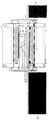
Referring to FIG. 2, a cross-sectional view of a magnet arrangement of the type commonly used for MR imaging is shown. The magnet assembly is generally cylindrical and annular in shape, and has an inner surface called a magnet room temperature bore 4, a passive magnet shim 5 (also shown in FIG. 1), a
[0016]
Typically, the
[0017]
Still referring to FIG. 2, the
[0018]
Still referring to FIG. 1, a cold bore 4 shows the generally cylindrical inner surface of the magnet assembly. This magnet room temperature bore is typically made of metal. There is a passive magnet shim 5 on the cylindrical inner surface of the room temperature bore 4. This shim 5 is used in a well-known manner in order to make a fine adjustment to the static magnetic field. The shim is typically a thin iron or steel strip.
[0019]
Still referring to FIG. 1, the imaging device further includes a pair of
[0020]
With reference to FIG. 3, the components of the imaging apparatus further include a support structure such as a patient bed or cradle 104 for inserting and positioning the subject 200 within the
[0021]
The
[0022]
[Outside 1]
Further, the current in the wire is typically as high as a few hundred amperes, and the static magnetic field can typically be in the range of 0.5T to 8T. Thus, this Lorentz force can be very large and cause significant vibrations in the tilt assembly. On the other hand, such vibrations may cause the sound to be heard by the ear by displacing the air. In addition, the vibration of this tilt assembly may be mechanically transmitted through the magnet-based structure, and this vibration may cause vibration to other parts in the structure, which may subsequently generate sound. . A second source of acoustic noise is due to Lorentz forces in the conductive parts that are not in contact with the tilt assembly. The reason for this force is that, for example, the pulsating magnetic field of the gradient field induces eddy currents in the various conductive components of the MRI system, and these eddy currents.
[0024]
[Outside 2]
The RF coil assembly is also a source of acoustic noise in MR imaging systems. The
[0026]
[Outside 3]
![]()
Generates Lenz force. These vibrations then generate acoustic noise that can be heard by the patient or system operator.
[0028]
In one embodiment of an imaging device for creating an MR image of a subject, the imaging device comprises a gradient coil assembly, an RF coil assembly, and a magnet assembly, each of these assemblies. Is selectively configured to reduce the generation and transmission of acoustic noise in and around the imaging device during imaging. Each of the tilt assembly, RF coil assembly, magnet assembly, and other components of the MRI system contributes to the source and propagation path of acoustic noise. An embodiment for reducing acoustic noise in each of these assemblies will be presented. It should be understood that in specific applications, the features of each embodiment relating to these assemblies and components can be combined to reduce the acoustic noise of the imaging device. Alternatively, each of these assemblies can be selectively configured to independently reduce the generation and transmission of acoustic noise. As used herein, expressions such as “configured to” indicate components that have the structure and functionality to perform the functions described.
[0029]
It is desirable that the
[0030]
The radio frequency (RF)
[0031]
In another alternative embodiment, noise reduction is achieved by making a cut in the conductor to interrupt the eddy current pattern, thereby reducing the eddy current as well as the associated Lorentz force.
[0032]
Referring to FIG. 5, another embodiment of an RF coil configured to reduce the generation and transmission of acoustic noise is shown. The
[0033]
In another embodiment of the noise reducing RF coil assembly, the large volume RF coil is fabricated so that there is no mechanical communication with the patient bore tube. Still referring to FIG. 1, a patient bore tube 1 is generally coupled to an RF coil assembly at its outer surface. In this embodiment, the
[0034]
In another embodiment of the imaging device, the magnet assembly is preferably configured to reduce the generation and transmission of acoustic noise in and around the imaging device. One source of acoustic noise in the magnet assembly is due to the passive shim 5. Typically, this shim is a thin sheet of steel. In these steel sheets, eddy currents are induced in the interior by the pulsed magnetic field from the gradient assembly, and the eddy currents collaborate with the static magnetic field in the magnetic field.
[0035]
[Outside 4]
![]()
Generate force. These vibrations may be transmitted to the outside of the magnet via a mechanical propagation path to the patient bore tube through the air (if not in a vacuum) or cryostat. Subsequent vibrations outside the magnet cryostat and patient bore tube generate significant acoustic noise that can be heard by the patient and the operator of the MRI system.
[0037]
Referring to FIG. 1, in a first embodiment of a magnet assembly for reducing noise, the passive shim 5 is made of a finely divided magnetic material mixed with a non-conductive polymer such as epoxy and then a sheet It is desirable to form it into a shape. In this embodiment, shim 5 is made of a mixture of 100 mesh steel powder (Ancorsteel 300SC) and polyethylene (Dowlex 2045, density ρPE = 0.92 g / cm 3) and pressed to a thickness in the range of 0.25 to 1.3 mm. And cut into strips. Although these sheets have magnetic properties that allow magnetic shim adjustment, this low conductivity or non-conductive material does not promote eddy currents and therefore is subject to pulsed gradient magnetic fields. Even so, the shim 5 does not vibrate. In the second embodiment, it is desirable that the passive shim 5 be isolated from the magnet room temperature bore with respect to vibration. In one embodiment, a layer of vibration isolation material is placed between the shim and the magnet bore. In this embodiment, it is desirable to further reduce the transmission of vibration energy from the shim to the magnet room temperature bore.
[0038]
The room temperature bore in the magnet assembly is also a source of acoustic noise. The magnet room temperature bore is typically made of a conductive material, and therefore may further facilitate the eddy current generated by the pulsed gradient magnetic field. The resulting vibration of the normal temperature bore may generate acoustic noise that is transmitted to the patient or MRI system operator by air or mechanical vibration.
[0039]
In another embodiment of a magnet assembly for reducing acoustic noise, the magnet room temperature bore 4 is configured to reduce the generation and transmission of acoustic noise. In one embodiment, the magnet room temperature bore 4 is preferably made of a non-conductive material such as FRP (glass fiber reinforced plastic). In another embodiment, the vacuum surrounding the magnet cold bore prevents air from transmitting sound from the magnet cold bore. The seal between the magnet cold bore and the rest of the magnet structure can be made to perform not only vacuum sealing but also vibration isolation. If the seal can isolate the room temperature bore from the rest of the magnet structure with respect to vibration, the vibration induced by the gradient magnetic field pulse in the room temperature bore is mechanically transmitted to the outside of the cryostat shell 7. There is nothing. Therefore, by isolating the magnet room temperature bore by vacuum and isolating the magnet room temperature bore by mechanical isolation, the vibration of the room temperature bore is prevented from generating acoustic noise that can be heard by the patient and the operator of the MRI system (or It is desirable to be able to reduce its ability. In yet another embodiment, the FRP is very thin (such as having a thickness on the order of micrometers or less than micrometers) to reduce the ingress of gas and water from the atmosphere through the surface of the cold bore. It is desirable to coat (metallize) the metal layer. If this metal layer is made sufficiently thin (so that the thickness is on the order of micrometers or less), the eddy current is substantially minimized in the metal layer and, as a result, the eddy current The vibration induced by the is also minimized.
[0040]
Still referring to FIG. 2, another embodiment of the magnet assembly includes a
[0041]
Another embodiment of the magnet assembly includes an embodiment of the cryostat shell 7 with reduced acoustic noise due to the cryostat shell 7. The cryostat shell is generally made of metal, typically steel or stainless steel. The vibration of the cryostat shell, whether it is a direct electromagnetic excitation from a pulsed gradient magnetic field or the result of mechanical transmission of vibrations elsewhere in the device, It may cause acoustic noise that can be heard by the operator of the MRI system.
[0042]
In another embodiment, the cryostat shell 7 is preferably made from a non-conductive material such as FRP. In yet another embodiment, the FRP includes a very thin wall (such as having a thickness on the order of micrometers or less than micrometers) to reduce gas and water ingress from the atmosphere through the cryostat shell. It is desirable to coat (metallize) the metal layer. If this metal layer is made sufficiently thin (so that the thickness is on the order of micrometers or less), the eddy current is substantially minimized in the metal layer and, as a result, the eddy current The vibration induced by the is also minimized.
[0043]
Still referring to FIG. 2, in another embodiment, the cryostat shell 7 is covered by a layer 17 of acoustic material to prevent and absorb possible vibrations, thereby creating a room or patient bore.1To prevent acoustic noise from being emitted. This layer 17 is a material such as an open cell foam such as “Soundfoam” by the Soundcoat Company designed for sound absorption, and in this embodiment is approximately 6 mm to 13 mm thick. Further, a constrained layer damping (CLD) layer that is preferably applied to the cryostat shell in a strip shape is disposed between the layer 17 and the cryostat shell. The CLD is generally composed of a thin plate with a sound attenuating material. The CLD material is applied to the structure so that the damping material is sandwiched between the thin plate and the structure (cryostat shell 7) to be attenuated. When vibration is transmitted through the structure, the structure is bent, and attenuation occurs in the sound-attenuating material sandwiched between the structures and the thin plate. This material can be effective in eliminating the effects of mechanical resonance that often tend to increase the sound level. In yet another embodiment, the
[0044]
In yet another embodiment of the magnet assembly, a mounting arrangement that prevents vibrations and the resulting acoustic noise is essential. For example, the vibration of the cryostat shell may be transmitted to the patient bore tube via a mechanical path from the cryostat shell 7 through the
[0045]
Still referring to FIG. 2, in another embodiment, the patient bore tube 1 includes a layer of sound absorbing material, such as “Soundfoam”, disposed on its inner surface. Patient bore tubes are typically made of rigid, non-conductive materials such as FRP (glass fiber reinforced plastic). The patient bore tube 1 may have mechanical resonances that tend to amplify vibrations transmitted to the patient tube via mechanical contact or air. In another embodiment, attenuation can be introduced to patient tube resonance by applying a non-conductive constrained layer attenuation (CLD) 100 in the form of a strip to the outer or inner surface of the patient bore tube 1.
[0046]
Referring to FIG. 6, another embodiment for reducing the generation of acoustic noise due to the conductive wire supplying power to the gradient coil is shown. A large current of 200 A or more typically flows through the conductive wire that supplies power to the gradient coil, and thus may receive a large Lorentz force. Referring to FIG. 1, a lead or wire (not shown) is routed through one of the end caps 12 and through a tilted
[0047]
Still referring to FIG. 6, the tilted
[0048]
Referring to FIG. 3, another source and propagation path of acoustic noise is used to interface the signals from the various RF coils with the electronics of the system typically placed outside the scanner. This may be caused by the cradle
[0049]
In another embodiment, it is desirable to isolate the electronic modules in the
[0050]
Although the invention has been described with reference to preferred embodiments, those skilled in the art will appreciate that the invention is not limited to these embodiments. One skilled in the art will appreciate that modifications may be made to the above-described embodiments that fall within the scope of the present invention.
[Brief description of the drawings]
FIG. 1 is a schematic side sectional view of an imaging apparatus to which a preferred embodiment of the present invention can be applied.
2 is a schematic cross-sectional view of the imaging apparatus of FIG. 1 taken along line 30-30 of FIG.
FIG. 3 is a schematic side sectional view of an MRI scanner to which a preferred embodiment of the present invention can be applied.
4 is a schematic diagram of an RF coil assembly of the type useful in the imaging apparatus of FIGS. 1 and 3. FIG.
5 is a schematic diagram of a type of RF coil assembly useful in the imaging apparatus of FIGS. 1 and 3. FIG.
6 is a schematic diagram of a type of gradient current feedthrough arrangement useful in the imaging apparatus of FIGS. 1 and 3. FIG.
[Explanation of symbols]
1 Patient bore tube
2 RF coil assembly
3 Gradient coil assembly
4 Magnet room temperature bore
5 Passive magnet shim
6 Magnet container
7 Cryostat shell
8 Bracket
9 Bracket
10 Isolation stack
11 Vacuum space
12 End cap
13 Suspension member
14Suspension strap
15 blocks
16 Constrained layer damping material
17 Acoustic material layer
20 End caps and seals
100 CLD material
101 Imaging volume, patient bore
102 bridge
103 central axis
104 Patient bed, cradle
105 Front bridge support
106 Rear bridge support
200 patients, subject
300 Cradle electronic circuit unit
400 RF coil
401 cylinder
402 conductor
500 RF coil assembly
501 cylinder
502 conductor
503 capacitor
504 Vibration isolation material
505 strap
600 inclined feedthrough assembly
601 End cap wall
602 Clearance Hall
603 Rod with thread
604 Rubber disc
605 washer
606 nut
607 rug
608 wire
Claims (5)
静磁場を生成するためのマグネット・アセンブリ(4、6、7)と、
前記マグネット・アセンブリ内の真空エンクロージャ(11)内に配置される、MR画像の作成の際に使用する磁場傾斜を生成するための傾斜コイル・アセンブリ(3)と、
円筒状に成形され、前記傾斜コイル・アセンブリと前記患者ボアチューブの間に収容される、高周波パルスを送信しかつ前記被検体より誘導されるMR信号を受信するための高周波(RF)コイル・アセンブリ(2)と、を備えており、
前記RFコイル・アセンブリ(2)は、高周波パルスを送信しかつ前記被検体より誘導されるMR信号を受信する前記円筒の円筒面に沿って鳥かご形構成で配置された複数の導体(502)を備えており、
前記複数の導体(502)の幅は、前記イメージング装置内の音響ノイズの要因となるうず電流の励起を低減するように選択されており、
前記RFコイル・アセンブリ(2)は、前記真空エンクロージャ(11)内で前記傾斜コイル・アセンブリ(3)の内側に配置されており、
前記導体(502)が振動隔絶材料(504)を介して、その内側表面に前記患者ボアチューブ(1)を収容するシリンダ(501)に装着され、3mm〜12mmの外径を有する複数のチューブを備えており、
前記真空エンクロージャ(11)内の真空は0.1〜200トル(Torr)の間であり、
前記傾斜コイル・アセンブリ(3)がさらに、外部電源からの傾斜用リードのための振動隔絶用フィードスルー・アセンブリ(600)を備えており、
前記マグネット・アセンブリが、外側表面(7)と、マグネット容器(6)と、前記マグネット容器を前記外側表面に取り付けるための複数の懸架部材(13)を備えており、前記懸架部材(13)の各々が、前記マグネット容器の振動を隔絶し、音響ノイズの発生及び伝達を低下させる、イメージング装置。Creating a magnetic resonance (MR) image of a subject (200) housed in a patient bore tube defining an imaging volume (101) and substantially minimizing acoustic noise generated during imaging An imaging device comprising:
A magnet assembly (4, 6, 7) for generating a static magnetic field;
A gradient coil assembly (3) disposed within a vacuum enclosure (11) within the magnet assembly for generating a magnetic field gradient for use in creating MR images;
A radio frequency (RF) coil assembly for transmitting radio frequency pulses and receiving MR signals derived from the subject, which is cylindrically shaped and received between the gradient coil assembly and the patient bore tube (2)
The RF coil assembly (2) includes a plurality of conductors (502) arranged in a birdcage configuration along a cylindrical surface of the cylinder that transmits high-frequency pulses and receives MR signals derived from the subject. Has
The width of the plurality of conductors (502) is selected to reduce excitation of eddy currents that cause acoustic noise in the imaging device;
The RF coil assembly (2) is disposed inside the gradient coil assembly (3) within the vacuum enclosure (11);
A plurality of tubes having an outer diameter of 3 mm to 12 mm, wherein the conductor (502) is attached to a cylinder (501) containing the patient bore tube (1) on its inner surface via a vibration isolation material (504). equipped and,
The vacuum in the vacuum enclosure (11) is between 0.1 and 200 Torr;
The gradient coil assembly (3) further comprises a vibration isolation feedthrough assembly (600) for a gradient lead from an external power source;
The magnet assembly includes an outer surface (7), a magnet container (6), and a plurality of suspension members (13) for attaching the magnet container to the outer surface. An imaging apparatus in which each isolates vibration of the magnet container and reduces the generation and transmission of acoustic noise .
Applications Claiming Priority (2)
| Application Number | Priority Date | Filing Date | Title |
|---|---|---|---|
| US09/676,945 US6437568B1 (en) | 2000-10-02 | 2000-10-02 | Low noise MRI scanner |
| US09/676945 | 2000-10-02 |
Publications (3)
| Publication Number | Publication Date |
|---|---|
| JP2002219112A JP2002219112A (en) | 2002-08-06 |
| JP2002219112A5 JP2002219112A5 (en) | 2005-06-23 |
| JP4049565B2 true JP4049565B2 (en) | 2008-02-20 |
Family
ID=24716667
Family Applications (1)
| Application Number | Title | Priority Date | Filing Date |
|---|---|---|---|
| JP2001304782A Expired - Lifetime JP4049565B2 (en) | 2000-10-02 | 2001-10-01 | Low noise MRI scanner |
Country Status (6)
| Country | Link |
|---|---|
| US (1) | US6437568B1 (en) |
| EP (1) | EP1193507B1 (en) |
| JP (1) | JP4049565B2 (en) |
| KR (1) | KR20020026835A (en) |
| CN (1) | CN1216286C (en) |
| DE (1) | DE60130854T2 (en) |
Families Citing this family (74)
| Publication number | Priority date | Publication date | Assignee | Title |
|---|---|---|---|---|
| US6567685B2 (en) * | 2000-01-21 | 2003-05-20 | Kabushiki Kaisha Toshiba | Magnetic resonance imaging apparatus |
| US6556012B2 (en) * | 2000-01-21 | 2003-04-29 | Kabushiki Kaisha Toshiba | Magnetic resonance imaging apparatus |
| US6954068B1 (en) | 2000-01-21 | 2005-10-11 | Kabushiki Kaisha Toshiba | Magnetic resonance imaging apparatus |
| DE10011034C2 (en) * | 2000-03-07 | 2002-06-06 | Siemens Ag | Magnetic resonance device with a gradient coil system with a coil arrangement |
| WO2002052292A1 (en) * | 2000-12-22 | 2002-07-04 | Koninklijke Philips Electronics N.V. | Medical examination apparatus provided with at least one magnet and noise-absorbing material |
| US6822448B2 (en) * | 2001-04-20 | 2004-11-23 | General Electric Company | RF coil for very high field magnetic resonance imaging |
| JP3878434B2 (en) * | 2001-05-10 | 2007-02-07 | ジーイー・メディカル・システムズ・グローバル・テクノロジー・カンパニー・エルエルシー | Coil structure for magnetic resonance imaging and magnetic resonance imaging apparatus |
| DE10127822B4 (en) * | 2001-06-07 | 2008-04-03 | Siemens Ag | Magnetic resonance device with a basic field magnet |
| US6627003B2 (en) * | 2001-10-24 | 2003-09-30 | Ge Medical Systems Global Technology Company, Llc | NMR shim forming method |
| DE10200861A1 (en) * | 2002-01-11 | 2003-07-31 | Siemens Ag | Magnetic resonance device with an eddy current generator |
| AU2003233920A1 (en) * | 2002-04-11 | 2003-10-27 | Siemens Aktiengesellschaft | Encapsulation of a magnetic resonance tomography device for attenuation of low sound frequencies |
| US6806558B2 (en) * | 2002-04-11 | 2004-10-19 | Triquint Semiconductor, Inc. | Integrated segmented and interdigitated broadside- and edge-coupled transmission lines |
| WO2003096042A1 (en) * | 2002-05-10 | 2003-11-20 | Siemens Aktiengesellschaft | Reduction of the sound emissions of thin-walled components in magnetic resonance devices |
| DE10253701B4 (en) * | 2002-11-18 | 2005-12-08 | Siemens Ag | Potted RF components, encapsulated gradient coil for Magnetic Resonance Imaging Scanner, with actuators for active noise abatement, as well as methods for their manufacture and apparatus for carrying out the method |
| US6894498B2 (en) * | 2003-03-12 | 2005-05-17 | Mrscience Llc | Active vibration compensation for MRI gradient coil support to reduce acoustic noise in MRI scanners |
| WO2004106960A1 (en) * | 2003-05-30 | 2004-12-09 | Koninklijke Philips Electronics N.V. | Magnetic resonance imaging scanner with molded fixed shims |
| US7068033B2 (en) * | 2003-08-18 | 2006-06-27 | Ge Medical Systems Global Technology Company, Llc | Acoustically damped gradient coil |
| US8354837B2 (en) | 2003-09-24 | 2013-01-15 | Ge Medical Systems Global Technology Company Llc | System and method for electromagnetic tracking operable with multiple coil architectures |
| DE102004004294A1 (en) * | 2004-01-28 | 2005-08-18 | Siemens Ag | Vacuum housing for a magnetic resonance device |
| JP2007526067A (en) * | 2004-03-03 | 2007-09-13 | コーニンクレッカ フィリップス エレクトロニクス エヌ ヴィ | Magnetic resonance imaging scanner with booster iron |
| US7372271B2 (en) | 2004-03-15 | 2008-05-13 | Koninklijke Philips Electronics N. V. | Main magnet perforated eddy current shield for a magnetic resonance imaging device |
| CN1947027B (en) * | 2004-04-26 | 2011-04-06 | 皇家飞利浦电子股份有限公司 | Electro-optical magnetic resonance transducer |
| US7755359B2 (en) * | 2004-05-31 | 2010-07-13 | Hitachi Medical Corporation | Magnetic resonance imaging apparatus with noise suppressing structure |
| ATE420375T1 (en) * | 2004-06-17 | 2009-01-15 | Koninkl Philips Electronics Nv | MAGNETIC RESONANCE IMAGING SYSTEM WITH IRON-ASSISTED MAGNETIC FIELD GRADIENT SYSTEM |
| WO2006054187A1 (en) * | 2004-11-17 | 2006-05-26 | Koninklijke Philips Electronics, N.V. | Magnetic resonance system with reduced noise |
| US7705701B2 (en) * | 2005-07-15 | 2010-04-27 | General Electric Company | Thin metal layer vacuum vessels with composite structural support |
| US7599728B2 (en) * | 2006-04-03 | 2009-10-06 | General Electric Company | Magnetic resonance imaging |
| US7671593B2 (en) * | 2006-06-15 | 2010-03-02 | General Electric Company | RF body coil with acoustic isolation of conductors |
| JP4237786B2 (en) * | 2006-09-27 | 2009-03-11 | 株式会社日立製作所 | Nuclear magnetic resonance signal solenoid coil and nuclear magnetic resonance probe |
| JP5032189B2 (en) * | 2007-04-18 | 2012-09-26 | ジーイー・メディカル・システムズ・グローバル・テクノロジー・カンパニー・エルエルシー | MRI apparatus and RF pulse generation circuit |
| DE102007025096B4 (en) * | 2007-05-30 | 2013-04-25 | Siemens Aktiengesellschaft | Method for determining the design of a main magnet of a magnetic resonance device with at least one gradient coil system |
| EP2191287A1 (en) * | 2007-09-07 | 2010-06-02 | Koninklijke Philips Electronics N.V. | Magnetic resonance examination system with reduced acoustic noise |
| GB2459502B (en) * | 2008-04-25 | 2010-03-03 | Siemens Magnet Technology Ltd | Vacuum vessel for cooled equipment |
| US7936170B2 (en) * | 2008-08-08 | 2011-05-03 | General Electric Co. | RF coil and apparatus to reduce acoustic noise in an MRI system |
| KR100971013B1 (en) * | 2008-09-04 | 2010-07-20 | 한양대학교 산학협력단 | Motor for magnetic resonance equipment and control method of the same |
| KR100971554B1 (en) * | 2008-10-20 | 2010-07-21 | 한양대학교 산학협력단 | Brushless motor for magnetic resonance equipment and control method of the same |
| JP5582756B2 (en) * | 2008-11-28 | 2014-09-03 | 株式会社東芝 | High frequency coil unit and magnetic resonance diagnostic apparatus |
| JP5586201B2 (en) * | 2009-10-05 | 2014-09-10 | 株式会社東芝 | Magnetic resonance diagnostic equipment |
| JP5815557B2 (en) * | 2009-12-28 | 2015-11-17 | コーニンクレッカ フィリップス エヌ ヴェKoninklijke Philips N.V. | Tubular thermal switch for refrigerant-free magnets |
| JP2011143033A (en) * | 2010-01-13 | 2011-07-28 | Toshiba Corp | Magnetic resonance imaging apparatus |
| JP5558863B2 (en) * | 2010-02-22 | 2014-07-23 | 株式会社東芝 | MRI equipment |
| EP2388610A1 (en) * | 2010-05-20 | 2011-11-23 | Koninklijke Philips Electronics N.V. | Magnetic Resonance Imaging Gradient Coil, Magnet Assembly, and System |
| US20120025829A1 (en) * | 2010-07-27 | 2012-02-02 | General Electric Company | Acoustically damped gradient coil |
| DE102010033330B4 (en) * | 2010-08-04 | 2014-04-30 | Siemens Aktiengesellschaft | Magnetic resonance antenna arrangement, magnetic resonance apparatus and method for acquisition of magnetic resonance signals |
| JP2011031103A (en) * | 2010-11-24 | 2011-02-17 | Toshiba Corp | Nuclear magnetic resonance imaging device |
| JP6104505B2 (en) * | 2011-01-13 | 2017-03-29 | 東芝メディカルシステムズ株式会社 | Magnetic resonance imaging system |
| US8710842B2 (en) * | 2011-03-07 | 2014-04-29 | General Electric Company | Apparatus and method to reduce noise in magnetic resonance imaging systems |
| US20120280688A1 (en) * | 2011-05-03 | 2012-11-08 | M2M Imaging Corp. | Magnetic Resonance (MR) Radio Frequency (RF) Coil and/or High Resolution Nuclear Magnetic Resonance |
| US8884620B2 (en) * | 2011-05-16 | 2014-11-11 | General Electric Company | RF body coil for reduced acoustic noise in an MR system |
| EP2718736A4 (en) * | 2011-06-13 | 2015-04-29 | William A Edelstein | Magnetic resonance imaging (mri) device noise dampening system |
| DE102011082410B4 (en) * | 2011-09-09 | 2015-02-12 | Siemens Aktiengesellschaft | A magnetic resonance apparatus |
| DE102011082411B4 (en) * | 2011-09-09 | 2015-02-12 | Siemens Aktiengesellschaft | A magnetic resonance apparatus |
| DE102011082401B4 (en) * | 2011-09-09 | 2015-01-08 | Siemens Aktiengesellschaft | A magnetic resonance apparatus |
| DE102011082402B4 (en) * | 2011-09-09 | 2015-01-08 | Siemens Aktiengesellschaft | A magnetic resonance apparatus |
| DE102012201485B4 (en) * | 2012-02-02 | 2019-02-21 | Siemens Healthcare Gmbh | A medical imaging device having a casing shell having a casing shell, and a method of manufacturing a casing shell of the medical imaging device |
| US9581665B2 (en) | 2012-04-20 | 2017-02-28 | General Electric Company | Systems and methods for damping common-mode energy |
| EP2845037B1 (en) * | 2012-04-30 | 2023-03-08 | Children's Hospital Medical Center | Acoustic noise reducing rf coil for magnetic resonance imaging |
| GB2503460B (en) * | 2012-06-26 | 2014-08-13 | Siemens Plc | Method and apparatus for reduction of gradient coil vibration in MRI systems |
| KR101417781B1 (en) * | 2012-09-24 | 2014-08-06 | 삼성전자 주식회사 | Magnetic resonance imaging device and manufacturing method thereof |
| EP2976654A2 (en) * | 2013-03-21 | 2016-01-27 | Koninklijke Philips N.V. | Mr image reconstruction using compressed sensing |
| DE102013213538B4 (en) | 2013-07-10 | 2018-08-16 | Siemens Healthcare Gmbh | Patient bore with integrated RF return space shaping to minimize the coupling between an energy chain and local RF transmit coils |
| DE102013218177A1 (en) * | 2013-09-11 | 2015-03-26 | Siemens Aktiengesellschaft | Device with a fastening device |
| US9989605B2 (en) * | 2013-11-22 | 2018-06-05 | Toshiba Medical Systems Corporation | Magnetic resonance imaging apparatus |
| JP6296576B2 (en) * | 2014-05-08 | 2018-03-20 | 株式会社日立製作所 | Magnetic resonance imaging system |
| US10132882B2 (en) | 2015-06-09 | 2018-11-20 | General Electric Company | Systems and methods for MRI body coil support structures |
| CN106443530A (en) * | 2015-08-13 | 2017-02-22 | 上海联影医疗科技有限公司 | Magnet assembly for magnetic resonance imaging, and manufacturing method thereof |
| CN105352690B (en) * | 2015-11-26 | 2018-01-23 | 清华大学 | Vibration measurement method of the medicine equipment in magnetic field |
| CN107768064B (en) * | 2016-08-19 | 2020-09-15 | 上海联影医疗科技有限公司 | Superconducting magnet assembly |
| CN106443531B (en) * | 2016-12-05 | 2024-04-12 | 苏州朗润医疗系统有限公司 | Combined noise reduction device and method for implementing combined noise reduction |
| CN107907844B (en) * | 2017-11-03 | 2020-04-24 | 上海联影医疗科技有限公司 | Magnetic resonance imaging apparatus and shimming method thereof |
| CN108287173A (en) * | 2018-01-12 | 2018-07-17 | 中国石油大学(北京) | Portable nuclear magnetic resonance detection device |
| CN109163099B (en) * | 2018-09-21 | 2021-03-02 | 国网湖南省电力有限公司 | Low-noise shaft end sealing structure for rotary machine |
| US10684336B2 (en) * | 2018-10-24 | 2020-06-16 | General Electric Company | Radiofrequency coil and shield in magnetic resonance imaging method and apparatus |
| DE102020201522A1 (en) | 2020-02-07 | 2021-08-12 | Bruker Switzerland Ag | NMR measurement setup with cold bore of the cryostat |
Family Cites Families (16)
| Publication number | Priority date | Publication date | Assignee | Title |
|---|---|---|---|---|
| US4840700A (en) | 1983-11-02 | 1989-06-20 | General Electric Company | Current streamline method for coil construction |
| JPH0284935A (en) * | 1988-06-14 | 1990-03-26 | Toshiba Corp | Magnetic resonance imaging device |
| US5235283A (en) * | 1991-02-07 | 1993-08-10 | Siemens Aktiengesellschaft | Gradient coil system for a nuclear magnetic resonance tomography apparatus which reduces acoustic noise |
| US5179338A (en) * | 1991-09-13 | 1993-01-12 | General Electric Company | Refrigerated superconducting MR magnet with integrated gradient coils |
| JP3161008B2 (en) * | 1992-03-18 | 2001-04-25 | 株式会社日立製作所 | Magnetic resonance imaging equipment |
| US5489848A (en) | 1992-09-08 | 1996-02-06 | Kabushiki Kaisha Toshiba | Magnetic resonance imaging apparatus |
| DE4432747C2 (en) * | 1993-09-17 | 1997-03-27 | Hitachi Medical Corp | Device and method for noise reduction in an MRI scanner |
| DE19531216C2 (en) * | 1995-08-24 | 1998-01-29 | Siemens Ag | Magnetic resonance device with at least one gradient coil attached to a holder |
| US5570021A (en) | 1995-10-10 | 1996-10-29 | General Electric Company | MR gradient set coil support assembly |
| US5793210A (en) | 1996-08-13 | 1998-08-11 | General Electric Company | Low noise MRI scanner |
| US5760584A (en) | 1996-08-16 | 1998-06-02 | General Electric Company | Shield for MR system RF coil provided with multiple capacitive channels for RF current flow |
| JP3619623B2 (en) * | 1996-10-17 | 2005-02-09 | 株式会社東芝 | Magnetic resonance imaging apparatus and sound insulation method for magnetic resonance imaging |
| DE19722481C2 (en) * | 1997-05-28 | 2000-02-10 | Siemens Ag | Magnetic resonance scanner and use of a noise reduction device in a magnetic resonance scanner |
| US5990681A (en) * | 1997-10-15 | 1999-11-23 | Picker International, Inc. | Low-cost, snap-in whole-body RF coil with mechanically switchable resonant frequencies |
| US6157276A (en) * | 1998-08-14 | 2000-12-05 | General Electric Company | MRI magnet assembly with non-conductive inner wall |
| DE19838390A1 (en) * | 1998-08-24 | 2000-03-02 | Siemens Ag | Noise reducing diagnostic magnetic resonance unit |
-
2000
- 2000-10-02 US US09/676,945 patent/US6437568B1/en not_active Expired - Lifetime
-
2001
- 2001-09-28 KR KR1020010060333A patent/KR20020026835A/en not_active Application Discontinuation
- 2001-09-29 CN CN011411783A patent/CN1216286C/en not_active Expired - Lifetime
- 2001-10-01 JP JP2001304782A patent/JP4049565B2/en not_active Expired - Lifetime
- 2001-10-02 EP EP01308414A patent/EP1193507B1/en not_active Expired - Lifetime
- 2001-10-02 DE DE60130854T patent/DE60130854T2/en not_active Expired - Lifetime
Also Published As
| Publication number | Publication date |
|---|---|
| CN1216286C (en) | 2005-08-24 |
| EP1193507A2 (en) | 2002-04-03 |
| EP1193507B1 (en) | 2007-10-10 |
| KR20020026835A (en) | 2002-04-12 |
| JP2002219112A (en) | 2002-08-06 |
| US6437568B1 (en) | 2002-08-20 |
| EP1193507A3 (en) | 2004-06-02 |
| CN1344928A (en) | 2002-04-17 |
| DE60130854T2 (en) | 2008-07-17 |
| DE60130854D1 (en) | 2007-11-22 |
Similar Documents
| Publication | Publication Date | Title |
|---|---|---|
| JP4049565B2 (en) | Low noise MRI scanner | |
| JP2002219112A5 (en) | ||
| US7375526B2 (en) | Active-passive electromagnetic shielding to reduce MRI acoustic noise | |
| US5793210A (en) | Low noise MRI scanner | |
| US6157276A (en) | MRI magnet assembly with non-conductive inner wall | |
| US6326788B1 (en) | MRI apparatus with a mechanically integrated eddy current shield in the gradient system | |
| US7141974B2 (en) | Active-passive electromagnetic shielding to reduce MRI acoustic noise | |
| CA2871384C (en) | Acoustic noise reducing rf coil for magnetic resonance imaging | |
| GB2406382A (en) | Acoustically Damped Gradient Coil | |
| WO2006054187A1 (en) | Magnetic resonance system with reduced noise | |
| US6894498B2 (en) | Active vibration compensation for MRI gradient coil support to reduce acoustic noise in MRI scanners | |
| EP1077382A2 (en) | Reduced noise RF coil apparatus for MR imaging system | |
| CN101796425A (en) | Magnetic resonance examination system with reduced acoustic noise | |
| JP2001509726A (en) | Magnetic resonance apparatus with force-optimized gradient coil | |
| US7053744B2 (en) | Encapsulation of a magnetic resonance tomography device for attenuation of low sound frequencies | |
| US20080315878A1 (en) | Actively Shielded Gradient Coil System Comprising Additional Additional Eddy Current Shield System | |
| JP2013013724A (en) | System and apparatus for balancing radial force in gradient coil | |
| JPH08266513A (en) | Magnetic resonance device for diagnosis | |
| JP3897958B2 (en) | Magnetic resonance imaging system | |
| JP2002085371A (en) | Magnetic resonance imaging apparatus | |
| JP2001198101A (en) | Magnetic resonance imaging system | |
| JPH11137535A (en) | Magnetic resonance imaging device | |
| JPH01208816A (en) | Magnet for nuclear magnetic resonance diagnostic apparatus |
Legal Events
| Date | Code | Title | Description |
|---|---|---|---|
| A521 | Request for written amendment filed |
Free format text: JAPANESE INTERMEDIATE CODE: A523 Effective date: 20041001 |
|
| A621 | Written request for application examination |
Free format text: JAPANESE INTERMEDIATE CODE: A621 Effective date: 20041001 |
|
| A977 | Report on retrieval |
Free format text: JAPANESE INTERMEDIATE CODE: A971007 Effective date: 20061026 |
|
| A131 | Notification of reasons for refusal |
Free format text: JAPANESE INTERMEDIATE CODE: A131 Effective date: 20061114 |
|
| A601 | Written request for extension of time |
Free format text: JAPANESE INTERMEDIATE CODE: A601 Effective date: 20070213 |
|
| A602 | Written permission of extension of time |
Free format text: JAPANESE INTERMEDIATE CODE: A602 Effective date: 20070219 |
|
| A521 | Request for written amendment filed |
Free format text: JAPANESE INTERMEDIATE CODE: A523 Effective date: 20070411 |
|
| A02 | Decision of refusal |
Free format text: JAPANESE INTERMEDIATE CODE: A02 Effective date: 20070522 |
|
| A521 | Request for written amendment filed |
Free format text: JAPANESE INTERMEDIATE CODE: A523 Effective date: 20070723 |
|
| A911 | Transfer to examiner for re-examination before appeal (zenchi) |
Free format text: JAPANESE INTERMEDIATE CODE: A911 Effective date: 20070829 |
|
| A131 | Notification of reasons for refusal |
Free format text: JAPANESE INTERMEDIATE CODE: A131 Effective date: 20071002 |
|
| A521 | Request for written amendment filed |
Free format text: JAPANESE INTERMEDIATE CODE: A523 Effective date: 20071010 |
|
| TRDD | Decision of grant or rejection written | ||
| A01 | Written decision to grant a patent or to grant a registration (utility model) |
Free format text: JAPANESE INTERMEDIATE CODE: A01 Effective date: 20071030 |
|
| A61 | First payment of annual fees (during grant procedure) |
Free format text: JAPANESE INTERMEDIATE CODE: A61 Effective date: 20071127 |
|
| R150 | Certificate of patent or registration of utility model |
Ref document number: 4049565 Country of ref document: JP Free format text: JAPANESE INTERMEDIATE CODE: R150 Free format text: JAPANESE INTERMEDIATE CODE: R150 |
|
| FPAY | Renewal fee payment (event date is renewal date of database) |
Free format text: PAYMENT UNTIL: 20101207 Year of fee payment: 3 |
|
| FPAY | Renewal fee payment (event date is renewal date of database) |
Free format text: PAYMENT UNTIL: 20101207 Year of fee payment: 3 |
|
| FPAY | Renewal fee payment (event date is renewal date of database) |
Free format text: PAYMENT UNTIL: 20111207 Year of fee payment: 4 |
|
| R250 | Receipt of annual fees |
Free format text: JAPANESE INTERMEDIATE CODE: R250 |
|
| FPAY | Renewal fee payment (event date is renewal date of database) |
Free format text: PAYMENT UNTIL: 20111207 Year of fee payment: 4 |
|
| FPAY | Renewal fee payment (event date is renewal date of database) |
Free format text: PAYMENT UNTIL: 20121207 Year of fee payment: 5 |
|
| R250 | Receipt of annual fees |
Free format text: JAPANESE INTERMEDIATE CODE: R250 |
|
| FPAY | Renewal fee payment (event date is renewal date of database) |
Free format text: PAYMENT UNTIL: 20131207 Year of fee payment: 6 |
|
| R250 | Receipt of annual fees |
Free format text: JAPANESE INTERMEDIATE CODE: R250 |
|
| R250 | Receipt of annual fees |
Free format text: JAPANESE INTERMEDIATE CODE: R250 |
|
| R250 | Receipt of annual fees |
Free format text: JAPANESE INTERMEDIATE CODE: R250 |
|
| R250 | Receipt of annual fees |
Free format text: JAPANESE INTERMEDIATE CODE: R250 |
|
| R250 | Receipt of annual fees |
Free format text: JAPANESE INTERMEDIATE CODE: R250 |
|
| R250 | Receipt of annual fees |
Free format text: JAPANESE INTERMEDIATE CODE: R250 |
|
| R250 | Receipt of annual fees |
Free format text: JAPANESE INTERMEDIATE CODE: R250 |
|
| R250 | Receipt of annual fees |
Free format text: JAPANESE INTERMEDIATE CODE: R250 |
|
| R250 | Receipt of annual fees |
Free format text: JAPANESE INTERMEDIATE CODE: R250 |