JP3897958B2 - Magnetic resonance imaging system - Google Patents
Magnetic resonance imaging system Download PDFInfo
- Publication number
- JP3897958B2 JP3897958B2 JP2000203695A JP2000203695A JP3897958B2 JP 3897958 B2 JP3897958 B2 JP 3897958B2 JP 2000203695 A JP2000203695 A JP 2000203695A JP 2000203695 A JP2000203695 A JP 2000203695A JP 3897958 B2 JP3897958 B2 JP 3897958B2
- Authority
- JP
- Japan
- Prior art keywords
- magnetic field
- field generating
- generating means
- resonance imaging
- imaging apparatus
- Prior art date
- Legal status (The legal status is an assumption and is not a legal conclusion. Google has not performed a legal analysis and makes no representation as to the accuracy of the status listed.)
- Expired - Fee Related
Links
Images


Description
【0001】
【発明の属する技術分野】
本発明は磁気共鳴イメージング(以下、MRIと称する)装置に係わり、特に、被検者に圧迫感を与えない開放型の磁石を採用したMRI装置において、検査に伴って発生する騒音を低減して被検者に快適な検査環境を提供するMRI装置に関する。
【0002】
【従来の技術】
核磁気共鳴(NMR)現象を利用して人体の断層画像を得るMRI装置は広く医療機関で利用されている。このMRI装置では、従来、均一な磁場空間を効率よく発生することができる細長い筒状のソレノイドコイルを用いていたが、被検者に対して圧迫感をなくし、また閉所恐怖症者や小児に対しても恐怖感を与えないために側面に閉口部を設けたり、被検者搬入部を広くなるように前面を開放構造にした磁石と平板型の傾斜磁場コイルを採用したオープンMRI装置が近年普及している。
【0003】
このような開放構造の磁石を用いたオープンMRI装置は検査中に治療を行うインターベンショナル手技が可能な空隙を有していることから、MRI検査でのインターベンショナル(以下、MRインターベンショナルと称す)が先進的な医療機関で進められている。このMRインターベンショナルでは、処置中のMRI画像をリアルタイムで術者が確認できる必要がある。
リアルタイムの撮影(高速撮影)で画質向上や機能の充実を実現するためには、MRI装置には高速で動作する傾斜磁場コイルとその駆動電源、高感度でNMR信号を検出する高周波コイル、そして、より高い静磁場強度を有する磁石が必要である。
高い静磁場強度の要請については、従来の永久磁石や常電導コイルを用いた磁石から、超電導コイルを組込んだ磁石の開発が進められている(例えば、特開平10-179546号公報、特開平11-155831号公報、特開平11-197132号公報など)。
【0004】
一方、傾斜磁場コイルについては、大容量のスイッチング電源などの開発が進み、高速駆動が可能となっている。しかし傾斜磁場駆動のための電流をパルス状に与えたときに電磁力が作用し、機械的歪と振動によって騒音が発生するという問題がある。
この問題はMRI装置を開放型にしたことに伴い、更に重大な問題となった。即ち、開放型のMRI装置は、ソレノイドコイルを用いた細長い検査空間のMRI装置に比べ振動の影響を受けやすく、磁石の振動はその発生する静磁場の安定度を低下させ、画像を劣化させる原因になる。また前述したようにリアルタイムの高速撮影では、傾斜磁場コイルを高速でスイッチング駆動するため騒音も振動も増大する。例えば、EPIイメージングのように傾斜磁場を高速でスイッチングする撮影手法を用いた検査では、傾斜磁場動作音が100dBAを越える場合もあった。
【0005】
従来、傾斜磁場コイルの振動と騒音の問題に対しては、傾斜磁場コイルボビンの剛性を強化する、傾斜磁場コイル自体の重量を増し振動振幅を制限する、傾斜磁場コイルの構造体内に多数の鉛玉を組み込み、傾斜磁場コイルの振動エネルギーを鉛玉同士の摩擦熱に変換する、傾斜磁場の騒音と逆位相の音を発生させ、
これらの方法はそれぞれ10dB程度の騒音低減の効果があったが、騒音低減量の割には、傾斜磁場コイル自体の重量増加や構造と制御方法が複雑になる問題点があった。
【0006】
【発明が解決しようとする課題】
これに対し、ソレノイドコイルを用いたMRI装置において、騒音低減効果をさらに高めた技術として、特開平10-118043号公報に記載されたMRI装置が提案されている。このMRI装置では、傾斜磁場コイルを真空密閉することが可能な設備で覆うとともに、傾斜磁場コイルを磁石に取付けるのでなく、磁石設置床に独立して設置するようにしている。この方法では、傾斜磁場コイル駆動に伴う空気伝播の振動と磁石に固定伝播する振動の両方を減少することができ、その結果、傾斜磁場コイルの振動に起因した装置全体の騒音を20〜30dB低減することができるとされている。
【0007】
しかし、この方法では、傾斜磁場コイルを磁石設置床に独立して設備する必要があるため、この設備が磁石周囲の床面と空隙を占有することになり、MRインターベンショナル手技に不都合となるおそれがある。また、この方法を高磁場開放型の磁石を用いたオープンMRI装置に適用しようとした場合、上下一対の傾斜磁場コイルのうち上側の傾斜磁場コイルを直接、磁石設置床に設備することは容易ではない。例えば上側の傾斜磁場コイルを安定に支持するためには複数の支柱が必要となるが、このような支柱は装置の側面に位置することになり、MRインターベンショナル手技を妨げると思われる。
【0008】
本発明は上記観点に鑑みてなされたもので、その目的はオープンMRI装置において、その磁石周囲の空隙を確保するとともに傾斜磁場駆動に伴う振動とこれに伴う騒音を低減することにある。また本発明の目的は、被検者に快適な検査環境が提供でき、また高速の撮影手法やそれを利用したMRインターベンショナル手技を低騒音で実施できるオープンMRI装置を提供することである。
【0009】
【課題を解決するための手段】
上記目的を達成する本発明のMRI装置は、一対の静磁場発生手段と、前記静磁場発生手段が発生する磁場に磁場強度勾配を与える一対の傾斜磁場発生手段と、前記一対の静磁場発生手段を支持する静磁場発生手段支持部とを備えたMRI装置において、前記一対の傾斜磁場発生手段の各々は、それぞれ前記静磁場発生手段に対し非接触であって前記静磁場発生手段支持部に固定されていることを特徴とする。
【0010】
本発明のMRI装置は、さらに静磁場発生手段が、磁場方向と同じ方向に貫通する空隙を備え、傾斜磁場発生手段は、前記空隙を介して前記静磁場発生手段支持部に固定されていることを特徴とする。傾斜磁場コイルを静磁場発生手段支持部に直接固定することにより、コイル自体の振動を抑制し、振動に起因する騒音を低減することができる。
特に静磁場発生手段支持部が鉄ヨークの場合は、一般にヨーク部は静磁場磁石に比べ非常に質量が大きいので、傾斜磁場コイルの振動がヨークから静磁場磁石に伝達されることはない。従って振動の固定伝播を効果的に抑制し、振動が静磁場磁石に与える影響、即ち磁場変動やそれに伴う画質の劣化を防止できる。さらにヨークは静磁場磁石の両側に配置されているので、磁石設置床や装置側面に特別な空間を設けることなく、傾斜磁場コイルを固定できる。これによりMRインターベンショナル手技を、装置の構造によって妨げられることなく実施できる。
【0011】
【発明の実施の形態】
以下、本発明の好適な実施形態について図面を参照して説明する。
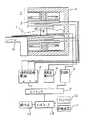
図1は本発明を適用したMRI装置の全体構成図である。このMRI装置は被検体1が置かれる空間を挟むように配置された一対の静磁場発生磁石2と、この静磁場発生磁石2の内側にそれぞれ配置された傾斜磁場コイル3と、さらにその内側に配置された高周波コイル5と、被検体1から発生するNMR信号を検出する検出コイル7とを備えている。傾斜磁場コイル3と高周波コイル5は開放型の形状を阻害しないように上下一対の板状構造をしている。
【0012】
このMRI装置は、さらに各コイルの動作タイミングを制御するシーケンサ9と、装置の制御を行うとともにNMR信号を処置し画像化するコンピュータ10と、被検体1を静磁場発生磁石2の中心空間に配設するテーブル14とを備えている。
【0013】
静磁場発生磁石2は、図示する実施形態では上下に分割された超電導磁石で構成されている。上下に対向配置された一対の超電導磁石は被検体1の周りにその体軸と直交する方向に均一な静磁場を発生させる。その磁場強度は、例えば1.0テスラで、磁束の方向は矢印15に示すように床から天井に向っており、その磁場均一度は被検体1が配設される球空間で約5ppm以下になるように調整されている。この磁場均一度調整は超電導磁石の表面に複数の磁性体小片(図では記載されていない)を貼り付けるパッシブシミング方式が用いられている。
さらに上下の超電導磁石を囲むように鉄ヨーク(ヨーク部)16が設けられている。鉄ヨーク16は、超電導磁石とともに磁気回路を構成し、磁石外に漏洩する磁束密度を低下させている。
【0014】
傾斜磁場コイル3は、互いに直交するx、y、zの3軸方向に磁束密度を変化させるように巻かれた3組のコイルからなり、それぞれ傾斜磁場電源4に接続され、傾斜磁場発生手段を構成する。シーケンサ9からの制御信号に従って傾斜磁場電源4を駆動して傾斜磁場コイル3に流れる電流値を変化させることにより3軸からなる傾斜磁場Gx、Gy、Gzを被検体1に印加するようになっている。この傾斜磁場は、被検体1の検査部位から得られるNMR信号の空間的な分布を把握するのに用いられる。
【0015】
傾斜磁場コイル3は、上下それぞれについてx、y、zのコイルを平板状に一体化にしたもので、鉄ヨーク16に直接固定されている。この傾斜磁場コイル3の構造および鉄ヨークへの取り付け構造については後に詳述する。
【0016】
高周波コイル5は、高周波コイル5と高周波電流を流すための高周波電力アンプ6に接続され、被検体1の検査部位の原子核(通常、水素原子核が用いられている)を共鳴励起するための高周波磁場を発生する。高周波電力アンプ6もシーケンサ9の制御信号で制御されている。
【0017】
検出コイル7は受信器8に接続されており、NMR信号を検出する手段を構成する。受信器8は検出コイル7で検出したNMR信号を増幅・検波するとともに、コンピュータ 10による処理が可能なディジタル信号に変換する。受信器8もシーケンサ9でその動作タイミングが制御されている。
【0018】
コンピュータ10はディジタル量に変換されたNMR信号を用いて画像再構成、スペクトル計算等の演算を行うとともに、シーケンサ9を介してMRI装置の各ユニットの動作を定められたタイミングで制御する。コンピュータ10とデータを記憶する記憶装置11と処理後のデータを表示するディスプレイ装置12と操作入力する操作卓13とで演算処理系が構成される。
【0019】
図2は、本発明の第1の実施形態として、図1に示すオープンMRI装置の静磁場発生磁石2と傾斜磁場コイル3の詳細な構造を示したものである。
【0020】
まず静磁場磁石2の構造について詳述する。図示する実施形態において、静磁場発生磁石2は超電導磁石方式で、上下一対の静磁場発生磁石2が被検体1が配設される磁場空間を挟んで鉄ヨーク26に固定されている。上下の静磁場発生磁石共に、ドーナツ型の形状を有するクライオ21と、クライオ21内に熱シールド板22を介して配置された液体ヘリウム槽24と、液体ヘリウム槽24内に収納された超電導コイル23とを備えている。
【0021】
クライオ21の内部は真空であり、液体ヘリウムの低温が保たれるようになっている。また液体ヘリウム槽24や熱シールド板22は液体ヘリウムの蒸発量を少なくするため、外部からの熱進入を防ぐため断熱特性の優れたワイヤー(図示せず)で支持されている。
【0022】
尚、図では1重の熱シールド板22のみを示したが、通常複数の熱シールド板22が配置される。また図では上下共に単一の超電導コイル23を示したが、発生磁場の均一度を向上する目的であるいは外部への漏洩磁場を少なくするために、大きさの異なる複数の超電導コイルが組込まれることもある。
【0023】
この上下クライオ21は、さらに図3に示すように、各ヘリウム槽24の液体ヘリウム量が均等になるように2本の連結管31で接続されている。尚、上部クライオ21には液体ヘリウムの消費量を低減させる目的でクライオクーラ32が組込まている。
【0024】
超電導コイル23には、約400アンペアの直流電流が流れており、中心空間で1.0テスラの磁場強度を発生している。このような高磁場の磁束が外部に漏洩するのを防止し、高磁場空間が最小限に収まるようにするために、上下クライオ21の外周部には、磁気回路を構成する鉄ヨーク26が組込まれている。
【0025】
図3に示す静磁場発生磁石2に鉄ヨーク26を組み込んだ状態を図4に示す。図示するように、鉄ヨーク26は超電導コイル23が発生する磁束に対して効率的な磁気回路を構成するように、上部プレート41と下部プレート42と左右の柱43、44で構成されている。左右の柱43、44は静磁場発生磁石2の前面空間が広くなるように後方にシフトして取り付けられている。
【0026】
一般に漏洩磁場は静磁場発生磁石2が設置される検査室(通常5×8メートル)内に収まるようにすることが望ましく、そのため磁気回路を構成する鉄ヨーク26は、鉄の固有値である飽和磁束密度とその断面積の積値が、超電導コイル23が発生する磁束以上でなければならい。ヨークを鉄材で構成する場合その重量は約35トンに達する。
【0027】
次にこのような鉄ヨーク26に固定される一対の平板型の傾斜磁場コイル3について説明する。
【0028】
図5は、平板型のx軸傾斜磁場コイルのパターンを示すもので、図中白く示されている部分が導体部分で、黒色の線で示す部分は、導体部分をエッチングした絶縁部である。このパターンのポイント51と52は電線53で接続されている。これによって端子54から端子55までが、全体として一筆書きのパターンを呈している。
【0029】
このようなx軸傾斜磁場コイルの端子54と55間に、矢印56で示す向きの電流が流れるように所定の電圧を印加すると、右半分の渦巻きパターンでは紙面の裏から表に向かう磁束が発生する。左半分の渦巻きパターンでは紙面の表から裏に向かう磁束が発生する。これによって紙面に直交する方向(z軸方向)の静磁場にx方向の磁場勾配を与えることができる。
【0030】
y軸傾斜磁場コイルは、構成はx軸傾斜磁場コイルと全く同じであり図示を省略するが、その配置される向きが、x軸傾斜磁場コイルに対し90度の角度となるように配置される。従ってy軸傾斜磁場の端子に所定の電圧を印加することにより、静磁場にy方向の磁場勾配を与えることができる。
【0031】
z軸傾斜磁場コイルは、図6に示すような単一の渦巻きパターンを有する。このようなパターンのコイル2個を検査空間を挟んで対向配置し、それぞれ逆向きの電流が流れるように端子61、62間に所定の電圧を印加することにより、z軸方向(紙面に垂直)に強度勾配を有する磁束が発生する。
【0032】
図1及び図2に示す上下の傾斜磁場コイル3は、それぞれこのようなパターンを有するxyz傾斜磁場コイルを、エポキシ系接着剤等の絶縁体を介して重ね一体化したものである。このような構成の傾斜磁場コイル3は、ドーナツ形状の静磁場発生磁石2の中央空隙を介して、コイル支持棒27とネジ28を介して鉄ヨークに固定されている。支持棒27はクライオ21(空隙の内壁)には接触しないようにその外径が空隙の内径より小さく設計されており、また傾斜磁場コイル3にかかる応力に対して充分な強度を有するように非磁性の金属材料(例えば、ステンレススチールやアルミニウム)で構成されている。
【0033】
MRIの検査では、前述したような高磁場、例えば1.0テスラの強度の磁束がz軸方向に発生している静磁場空間内で、これら傾斜磁場コイルにパルス状の電流が印加される。これにより傾斜磁場コイル3には複雑な応力がかかることになる。このような傾斜磁場コイル3に発生した応力は、支持棒27を介して鉄ヨーク26に直接加えられ、上下クライオ21には直接伝わることはない。また前述したように鉄ヨーク26の重量は約35トンであり、傾斜磁場コイル3の応力エネルギーを吸収することになるので、固体伝播により振動が上下クライオ21が伝わるのを防ぐことができる。
【0034】
さらに傾斜磁場コイル3を支持するための機構(支持棒27)は、上下クライオ21の内部を利用して配置することができるので、このような機構が静磁場発生磁石2の周辺空間を占めることなく、MRインターベンショナル術者が有効に使うことができる。
【0035】
次に本発明の第2の実施形態を説明する。
図7は第2の実施形態のオープンMRI装置を示す図であり、静磁場発生磁石2と傾斜磁場コイル3の取り付け構造の以外の構成は、図2のMRI装置と同じであるのでその説明を省略する。
【0036】
第2の実施形態においても静磁場発生磁石2は超電導磁石方式で、その構造は第1の実施形態とほぼ同じ同様であり、上下一対のクライオ71と、クライオ71に収納された熱シールド板72と、超電導コイル73が収められた液体ヘリウム槽74とを備えている。ここでも熱シールド板72は複数であってもよく、または超電導コイル73も複数組み込まれていてもよい。また上下クライオ71の外周部には、磁気回路を構成する鉄ヨーク26が組込まれている。
【0037】
しかしこの実施形態では、クライオ71はドーナツ形状ではなく円筒形であり、一対の傾斜磁場コイル3は、この円筒形の上下クライオ71の外側に位置する支持リング75を介して鉄ヨーク26に固定されている。
【0038】
この実施形態の場合、傾斜磁場コイル3の外周部が支持リング75によって強固に鉄ヨーク26に固定されるのでより一層の剛性を持たせることができる。これにより固体伝播による振動騒音の低減効果も向上する。ここでも支持リング75の材質は、第1の実施形態と同様に非磁性の金属材料(例えば、ステンレススチールやアルミニウム)を採用することも可能であるが、支持リング75の材質を強磁性体にすることで、超電導コイル74の側面からの漏洩磁束に対しても磁気シールド効果が得られる。従って第1の実施形態に比べてよりコンパクトに静磁場発生磁石2を構成することができる。このことはMRインターベンショナル使用にあたってより好適な術者空間を提供することになる。
【0039】
図8は本発明の第3の実施形態によるオープンMRI装置を示す図である。この実施形態では、第1の実施形態と第2の実施形態を組み合わせた傾斜磁場コイル3の取り付け構造になっている。
即ち、静磁場発生磁石2は第1の実施形態と同様にドーナツ形状であり、傾斜磁場コイル3はドーナツ中心の空隙を利用して、支持棒82とネジ84とにより鉄ヨーク26に固定されるとともに、その周囲を支持リング83とネジ84で鉄ヨーク26に直接固定されている。
【0040】
この実施形態の場合、傾斜磁場コイル3の外周部が支持棒82と支持リング83を介して鉄ヨーク26に強固に固定されるのでより一層の剛性を持たせることができる。また、傾斜磁場コイル3の中央部分が支持棒82により鉄ヨーク26に固定されているので、傾斜磁場コイル3の振動振幅が抑制され、より一層傾斜磁場コイル3の振動に伴う騒音を低減できる。ここでも支持リング83を強磁性体で構成することにより、磁気シールド効果が得られ、よりコンパクトに静磁場発生磁石2を構成することができる。
また本実施形態の場合は、傾斜磁場コイル3を吸音マット85で覆った構成としている。このような吸音マット85を併用することにより、傾斜磁場コイル3のより高い周波数の振動モードにも対応することができ、これに高い騒音の減衰効果が得られる。
【0041】
このように本発明のMRI装置では、第3の実施形態に限らず、従来技術として知られている他の振動騒音抑制技術を併用することが可能であり、これにより種々の振動モードや騒音を効果的に抑制することができる。
また以上の実施形態では、静磁場発生磁石が超電導磁石である場合について説明し、その場合に本発明の高い効果が期待できるが、本発明は超電導磁石に限らず、永久磁石や常電導磁石を用いたオープンMRI装置であっても同様に適用することができる。
【0042】
【発明の効果】
以上述べたように、傾斜磁場コイルをヨークに取付けることで、傾斜磁場コイル駆動に伴う固体伝磯の振動を減衰することができる。さらに、傾斜磁場コイルに減音カバーを取り付けることにより、空気伝搬の振動による騒音を減衰することができる。この結果、高磁場オープンMRI装置で高速の撮影手法を実施しても、その磁石周囲の空間を確保するとともに傾斜磁場駆動に伴う振動とこれに起因する騒音を低減することができる。これにより、被検者に快適な検査環境と、MRインターベンショナル手技を可能としたオープンMRI装置を提供することができる。
【図面の簡単な説明】
【図1】本発明が適用されるMRI装置の全体構成を示す図。
【図2】本発明の第1実施形態によるMRI装置の要部を示す図。
【図3】図2のMRI装置の超電導磁石のクライオ部分を示す斜視図。
【図4】図2のMRI装置の超電導磁石全体を示す斜視図。
【図5】 x軸傾斜磁場コイルのパターン図。
【図6】 z軸傾斜磁場コイルのパターン図。
【図7】本発明の第2実施形態によるMRI装置の要部を示す図。
【図8】本発明の第3実施形態によるMRI装置の要部を示す図。
【符号の説明】
1……被検体
2……静磁場発生磁石
3……傾斜磁場コイル
4……傾斜磁場電源
5……高周波コイル
6……高周波電力アンプ
7……検出コイル
8……受信器
9……シーケンサ
10……コンピュータ
21……クライオ
26……鉄ヨーク
27……支持棒
75……支持リング
85……吸音マット[0001]
BACKGROUND OF THE INVENTION
The present invention relates to a magnetic resonance imaging (hereinafter referred to as MRI) apparatus, and in particular, in an MRI apparatus that employs an open magnet that does not give a sense of pressure to a subject, noise generated with an examination is reduced. The present invention relates to an MRI apparatus that provides a comfortable examination environment for a subject.
[0002]
[Prior art]
MRI apparatuses that obtain a tomographic image of the human body using the nuclear magnetic resonance (NMR) phenomenon are widely used in medical institutions. Conventionally, this MRI apparatus has used a long and slender cylindrical solenoid coil that can efficiently generate a uniform magnetic field space. However, this MRI apparatus eliminates the feeling of pressure on the subject, and also helps claustrophobic patients and children. In recent years, an open MRI system that employs a magnet with a closed front surface and a flat-plate gradient magnetic field coil to provide a closed part on the side surface so as not to give a sense of fear, or to widen the carry-in part of the subject It is popular.
[0003]
Since an open MRI device using such an open-structured magnet has a gap that allows interventional procedures to perform treatment during the examination, interventional MRI examination (hereinafter referred to as MR interventional) Is being promoted by advanced medical institutions. In this MR interventional, the operator needs to be able to confirm the MRI image being treated in real time.
In order to realize image quality improvement and enhancement of functions in real-time imaging (high-speed imaging), the MRI apparatus has a gradient magnetic field coil that operates at high speed and its driving power supply, a high-frequency coil that detects NMR signals with high sensitivity, and A magnet with a higher static magnetic field strength is needed.
With regard to the demand for high static magnetic field strength, development of magnets incorporating superconducting coils is being promoted from conventional permanent magnets and magnets using normal conducting coils (for example, JP-A-10-179546, JP 11-155831, JP-A-11-197132, etc.).
[0004]
On the other hand, with regard to the gradient magnetic field coil, development of a large-capacity switching power supply and the like has progressed, and high speed driving is possible. However, there is a problem that an electromagnetic force acts when a current for driving the gradient magnetic field is applied in a pulse shape, and noise is generated due to mechanical strain and vibration.
This problem became even more serious with the opening of the MRI system. That is, an open MRI device is more susceptible to vibration than an MRI device with a long and narrow examination space using a solenoid coil, and the vibration of the magnet reduces the stability of the generated static magnetic field and causes image deterioration. become. Further, as described above, in real-time high-speed imaging, the gradient magnetic field coil is switched at a high speed, so that noise and vibration increase. For example, in an examination using an imaging technique that switches a gradient magnetic field at high speed, such as EPI imaging, the gradient magnetic field operation sound sometimes exceeded 100 dBA.
[0005]
Conventionally, in order to solve the problems of vibration and noise of the gradient coil, a large number of lead balls in the structure of the gradient coil, which increases the rigidity of the gradient coil bobbin, increases the weight of the gradient coil itself, and limits the vibration amplitude. , Which generates vibrations with opposite phase to the noise of the gradient magnetic field, which converts the vibration energy of the gradient magnetic field coil into frictional heat between lead balls,
Each of these methods had an effect of reducing noise by about 10 dB. However, there were problems in that the weight of the gradient coil itself and the structure and control method were complicated for the amount of noise reduction.
[0006]
[Problems to be solved by the invention]
On the other hand, an MRI apparatus described in Japanese Patent Laid-Open No. 10-118043 has been proposed as a technique for further enhancing the noise reduction effect in an MRI apparatus using a solenoid coil. In this MRI apparatus, the gradient magnetic field coil is covered with an equipment capable of being hermetically sealed, and the gradient magnetic field coil is not attached to the magnet but is installed independently on the magnet installation floor. This method can reduce both the vibration of air propagation caused by the gradient coil drive and the vibration that is fixedly propagated to the magnet, and as a result, the noise of the entire device due to the vibration of the gradient coil is reduced by 20 to 30 dB. It is supposed to be possible.
[0007]
However, in this method, since the gradient coil needs to be installed independently on the magnet installation floor, this installation occupies the floor surface around the magnet and the gap, which is inconvenient for the MR interventional procedure. There is a fear. In addition, when this method is applied to an open MRI apparatus using a high magnetic field open type magnet, it is not easy to install the upper gradient magnetic field coil directly on the magnet installation floor among the upper and lower gradient magnetic field coils. Absent. For example, a plurality of support columns are required to stably support the upper gradient coil, but such support columns will be located on the side of the apparatus, which may hinder MR interventional procedures.
[0008]
The present invention has been made in view of the above viewpoint, and an object of the present invention is to secure a gap around the magnet and reduce vibrations accompanying the gradient magnetic field drive and noises associated therewith in an open MRI apparatus. Another object of the present invention is to provide an open MRI apparatus that can provide a comfortable examination environment for a subject and that can perform a high-speed imaging technique and MR interventional technique using the same with low noise.
[0009]
[Means for Solving the Problems]
The MRI apparatus of the present invention that achieves the above object comprises a pair of static magnetic field generating means, a pair of gradient magnetic field generating means for giving a magnetic field strength gradient to the magnetic field generated by the static magnetic field generating means, and the pair of static magnetic field generating means In the MRI apparatus provided with a static magnetic field generating means supporting portion that supports the magnetic field generating means, each of the pair of gradient magnetic field generating means is not in contact with the static magnetic field generating means and is fixed to the static magnetic field generating means support portion. It is characterized by being.
[0010]
In the MRI apparatus of the present invention, the static magnetic field generation means further includes a gap penetrating in the same direction as the magnetic field direction, and the gradient magnetic field generation means is fixed to the static magnetic field generation means support portion via the gap. It is characterized by. By directly fixing the gradient magnetic field coil to the static magnetic field generating means supporting portion, vibration of the coil itself can be suppressed and noise caused by the vibration can be reduced.
In particular, when the static magnetic field generating means supporting portion is an iron yoke , the yoke portion generally has a much larger mass than the static magnetic field magnet, so that the vibration of the gradient magnetic field coil is not transmitted from the yoke to the static magnetic field magnet. Therefore, it is possible to effectively suppress the fixed propagation of vibration, and to prevent the influence of vibration on the static magnetic field magnet, that is, the fluctuation of the magnetic field and the accompanying image quality deterioration. Furthermore, since the yoke is disposed on both sides of the static magnetic field magnet, the gradient magnetic field coil can be fixed without providing a special space on the magnet installation floor or the side of the apparatus. This allows MR interventional procedures to be performed without being hindered by the structure of the device.
[0011]
DETAILED DESCRIPTION OF THE INVENTION
Preferred embodiments of the present invention will be described below with reference to the drawings.
FIG. 1 is an overall configuration diagram of an MRI apparatus to which the present invention is applied. This MRI apparatus includes a pair of static magnetic
[0012]
The MRI apparatus further includes a sequencer 9 that controls the operation timing of each coil, a
[0013]
In the illustrated embodiment, the static magnetic
Further, an iron yoke (yoke part) 16 is provided so as to surround the upper and lower superconducting magnets. The iron yoke 16 constitutes a magnetic circuit together with the superconducting magnet, and reduces the magnetic flux density leaking outside the magnet.
[0014]
The gradient
[0015]
The gradient
[0016]
The high-
[0017]
The detection coil 7 is connected to the
[0018]
The
[0019]
FIG. 2 shows a detailed structure of the static magnetic
[0020]
First, the structure of the static
[0021]
The inside of the
[0022]
Although only a single
[0023]
Further, as shown in FIG. 3, the upper and
[0024]
A DC current of about 400 amperes flows through the
[0025]
FIG. 4 shows a state in which the
[0026]
In general, it is desirable that the leakage magnetic field be within the inspection room (usually 5 × 8 meters) in which the static magnetic
[0027]
Next, a pair of flat type gradient magnetic field coils 3 fixed to the
[0028]
FIG. 5 shows a pattern of a flat plate-type x-axis gradient magnetic field coil. A white portion in the drawing is a conductor portion, and a black line portion is an insulating portion obtained by etching the conductor portion. The
[0029]
When a predetermined voltage is applied between the
[0030]
The configuration of the y-axis gradient magnetic field coil is exactly the same as that of the x-axis gradient magnetic field coil and is not shown in the figure, but is arranged so that its orientation is at an angle of 90 degrees with respect to the x-axis gradient magnetic field coil. . Therefore, a magnetic field gradient in the y direction can be applied to the static magnetic field by applying a predetermined voltage to the terminal of the y-axis gradient magnetic field.
[0031]
The z-axis gradient magnetic field coil has a single spiral pattern as shown in FIG. Two coils with such a pattern are placed facing each other across the inspection space, and a predetermined voltage is applied between the
[0032]
The upper and lower gradient magnetic field coils 3 shown in FIGS. 1 and 2 are obtained by integrating xyz gradient magnetic field coils each having such a pattern with an insulating material such as an epoxy-based adhesive overlapped. The gradient
[0033]
In the MRI examination, a pulsed current is applied to these gradient magnetic field coils in a static magnetic field space in which a magnetic field as described above, for example, a magnetic flux having a strength of 1.0 Tesla is generated in the z-axis direction. As a result, a complicated stress is applied to the
[0034]
Furthermore, since the mechanism (support rod 27) for supporting the gradient
[0035]
Next, a second embodiment of the present invention will be described.
FIG. 7 is a diagram showing the open MRI apparatus of the second embodiment, and the configuration other than the mounting structure of the static magnetic
[0036]
Also in the second embodiment, the static magnetic
[0037]
However, in this embodiment, the cryo 71 is not a donut shape but a cylindrical shape, and the pair of gradient magnetic field coils 3 are fixed to the
[0038]
In the case of this embodiment, since the outer peripheral portion of the
[0039]
FIG. 8 is a diagram showing an open MRI apparatus according to the third embodiment of the present invention. In this embodiment, the gradient
That is, the static magnetic
[0040]
In the case of this embodiment, the outer peripheral portion of the gradient
In the present embodiment, the gradient
[0041]
As described above, in the MRI apparatus of the present invention, not only the third embodiment but also other vibration noise suppression techniques known as conventional techniques can be used in combination. It can be effectively suppressed.
In the above embodiment, the case where the static magnetic field generating magnet is a superconducting magnet will be described. In that case, the high effect of the present invention can be expected, but the present invention is not limited to the superconducting magnet, and a permanent magnet or a normal conducting magnet is used. The same applies to the open MRI apparatus used.
[0042]
【The invention's effect】
As described above, by attaching the gradient magnetic field coil to the yoke, it is possible to dampen the vibration of the solid transmission accompanying the gradient magnetic field coil driving. Furthermore, noise due to vibration of air propagation can be attenuated by attaching a sound reduction cover to the gradient magnetic field coil. As a result, even when a high-speed imaging method is performed with a high magnetic field open MRI apparatus, it is possible to secure a space around the magnet and reduce vibrations caused by the gradient magnetic field drive and noise caused thereby. As a result, it is possible to provide an open MRI apparatus that enables a test environment comfortable for the subject and MR interventional procedures.
[Brief description of the drawings]
FIG. 1 is a diagram showing an overall configuration of an MRI apparatus to which the present invention is applied.
FIG. 2 is a diagram showing a main part of the MRI apparatus according to the first embodiment of the present invention.
3 is a perspective view showing a cryo part of a superconducting magnet of the MRI apparatus of FIG. 2. FIG.
4 is a perspective view showing the entire superconducting magnet of the MRI apparatus of FIG. 2;
FIG. 5 is a pattern diagram of an x-axis gradient magnetic field coil.
FIG. 6 is a pattern diagram of a z-axis gradient magnetic field coil.
FIG. 7 is a diagram showing a main part of an MRI apparatus according to a second embodiment of the present invention.
FIG. 8 is a diagram showing a main part of an MRI apparatus according to a third embodiment of the present invention.
[Explanation of symbols]
DESCRIPTION OF SYMBOLS 1 ... Subject 2 ... Static magnetic
10 …… Computer
21 …… Cryo
26 …… iron yoke
27 …… Supporting rod
75 …… Support ring
85 …… Sound absorption mat
Claims (8)
前記一対の傾斜磁場発生手段の各々は、前記静磁場の方向に垂直な面を有する平板状に形成されており、
前記支持手段は、前記傾斜磁場発生手段をその面に略垂直に支持すると共に前記静磁場発生手段に対し非接触に前記静磁場発生手段支持手段に固定することを特徴とする磁気共鳴イメージング装置。 Each of a pair of static magnetic field generating means arranged opposite to each other with a gap space in between has a static magnetic field generation source, forms a static magnetic field in the gap space, and supports the pair of static magnetic field generation means A generating means supporting means; a pair of gradient magnetic field generating means that are disposed opposite to the inside of the static magnetic field generating means with the gap space interposed therebetween to give a magnetic field strength gradient to the static magnetic field; and the pair of gradient magnetic field generating means A magnetic resonance imaging apparatus comprising: support means for supporting each of
Each of the pair of gradient magnetic field generating means is formed in a flat plate shape having a surface perpendicular to the direction of the static magnetic field,
The magnetic resonance imaging apparatus characterized in that the supporting means supports the gradient magnetic field generating means substantially perpendicularly to the surface thereof, and is fixed to the static magnetic field generating means supporting means in a non-contact manner with respect to the static magnetic field generating means.
前記支持手段は、該支持手段及び前記傾斜磁場発生手段と前記静磁場発生手段との間に空隙を確保して、前記傾斜磁場発生手段の振動を前記静磁場発生手段に直接伝搬させないように、前記傾斜磁場発生手段を前記静磁場発生手段支持手段に固定することを特徴とする磁気共鳴イメージング装置。 The magnetic resonance imaging apparatus according to claim 1.
The support means secures a gap between the support means and the gradient magnetic field generation means and the static magnetic field generation means, so that the vibration of the gradient magnetic field generation means is not directly propagated to the static magnetic field generation means. A magnetic resonance imaging apparatus, wherein the gradient magnetic field generating means is fixed to the static magnetic field generating means supporting means .
前記静磁場発生手段は磁場方向と同じ方向に貫通する空隙を備え、
前記支持手段は、前記空隙内に配置された支持部材を含む支持構造体を有して、
前記傾斜磁場発生手段は、その中央部にて、前記支持構造体を介して前記静磁場発生手段支持手段に固定されていることを特徴とする磁気共鳴イメージング装置。The magnetic resonance imaging apparatus according to claim 1.
The static magnetic field generating means includes a gap penetrating in the same direction as the magnetic field direction,
The support means has a support structure including a support member disposed in the gap,
It said gradient magnetic field generating means, at its central portion, magnetic resonance imaging apparatus characterized by being fixed to the static magnetic field generating means support means via said supporting lifting structure.
前記支持手段は、前記静磁場発生手段を非接触に取り囲む支持部材を有して、
前記傾斜磁場発生手段は、その周辺部にて、前記支持部材を介して前記静磁場発生手段支持手段に固定されていることを特徴とする磁気共鳴イメージング装置。The magnetic resonance imaging apparatus according to claim 1.
The support means includes a support member that surrounds the static magnetic field generation means in a non-contact manner,
Said gradient magnetic field generating means, a magnetic resonance imaging apparatus, characterized in that the at periphery is fixed to the static magnetic field generating means support means through said supporting support member.
前記支持手段は、前記静磁場発生手段を非接触に取り囲む支持部材を有して、
前記傾斜磁場発生手段は、さらにその周縁部にて、前記支持部材を介して前記静磁場発生手段支持手段に固定されていることを特徴とする磁気共鳴イメージング装置。 The magnetic resonance imaging apparatus according to claim 3.
The support means includes a support member that surrounds the static magnetic field generation means in a non-contact manner,
The magnetic resonance imaging apparatus according to claim 1, wherein the gradient magnetic field generating means is further fixed to the static magnetic field generating means supporting means via the support member at a peripheral portion thereof .
前記静磁場発生手段支持手段は、前記一対の静磁場発生手段を囲んで磁気回路を形成する鉄ヨークを含むことを特徴とする磁気共鳴イメージング装置。 The magnetic resonance imaging apparatus according to any one of claims 1 to 7 ,
The magnetic resonance imaging apparatus according to claim 1, wherein the static magnetic field generating means supporting means includes an iron yoke that surrounds the pair of static magnetic field generating means and forms a magnetic circuit.
Priority Applications (3)
| Application Number | Priority Date | Filing Date | Title |
|---|---|---|---|
| JP2000203695A JP3897958B2 (en) | 2000-07-05 | 2000-07-05 | Magnetic resonance imaging system |
| PCT/JP2001/005704 WO2002002010A1 (en) | 2000-07-05 | 2001-07-02 | Magnetic resonance imaging device and gradient magnetic field coil used for it |
| US10/332,069 US6933722B2 (en) | 2000-07-05 | 2001-07-02 | Magnetic resonance imaging device and gradient magnetic field coil used for it |
Applications Claiming Priority (1)
| Application Number | Priority Date | Filing Date | Title |
|---|---|---|---|
| JP2000203695A JP3897958B2 (en) | 2000-07-05 | 2000-07-05 | Magnetic resonance imaging system |
Publications (3)
| Publication Number | Publication Date |
|---|---|
| JP2002017705A JP2002017705A (en) | 2002-01-22 |
| JP2002017705A5 JP2002017705A5 (en) | 2006-03-23 |
| JP3897958B2 true JP3897958B2 (en) | 2007-03-28 |
Family
ID=18701069
Family Applications (1)
| Application Number | Title | Priority Date | Filing Date |
|---|---|---|---|
| JP2000203695A Expired - Fee Related JP3897958B2 (en) | 2000-07-05 | 2000-07-05 | Magnetic resonance imaging system |
Country Status (1)
| Country | Link |
|---|---|
| JP (1) | JP3897958B2 (en) |
Families Citing this family (8)
| Publication number | Priority date | Publication date | Assignee | Title |
|---|---|---|---|---|
| WO2004081596A1 (en) * | 2003-03-13 | 2004-09-23 | Koninklijke Philips Electronics N.V. | Mri system having a gradient magnet system with a gyroscope |
| WO2004093681A1 (en) * | 2003-04-23 | 2004-11-04 | Hitachi Medical Corporation | Magnetic resonance imaging device |
| JP4822439B2 (en) | 2004-05-31 | 2011-11-24 | 株式会社日立メディコ | Magnetic resonance imaging system |
| JP2006141614A (en) | 2004-11-18 | 2006-06-08 | Mitsubishi Electric Corp | Magnet system, method of installing magnet system, and magnetic resonance image diagnostic apparatus |
| JP4266232B2 (en) | 2006-11-17 | 2009-05-20 | 株式会社日立製作所 | Superconducting magnet apparatus and magnetic resonance imaging apparatus |
| JP5224275B2 (en) * | 2008-03-28 | 2013-07-03 | 日立金属株式会社 | PET / MRI integrated device |
| US9989605B2 (en) * | 2013-11-22 | 2018-06-05 | Toshiba Medical Systems Corporation | Magnetic resonance imaging apparatus |
| JP6341535B2 (en) * | 2014-04-30 | 2018-06-13 | 株式会社エム・アール・テクノロジー | Imaging unit |
-
2000
- 2000-07-05 JP JP2000203695A patent/JP3897958B2/en not_active Expired - Fee Related
Also Published As
| Publication number | Publication date |
|---|---|
| JP2002017705A (en) | 2002-01-22 |
Similar Documents
| Publication | Publication Date | Title |
|---|---|---|
| US6933722B2 (en) | Magnetic resonance imaging device and gradient magnetic field coil used for it | |
| US5600245A (en) | Inspection apparatus using magnetic resonance | |
| US7375526B2 (en) | Active-passive electromagnetic shielding to reduce MRI acoustic noise | |
| JP4037272B2 (en) | Magnetic resonance imaging apparatus and static magnetic field generator used therefor | |
| US7372271B2 (en) | Main magnet perforated eddy current shield for a magnetic resonance imaging device | |
| EP0817211B1 (en) | Superconducting magnet device and magnetic resonance imaging device using the same | |
| US7141974B2 (en) | Active-passive electromagnetic shielding to reduce MRI acoustic noise | |
| JP6480732B2 (en) | System and apparatus for compensating for magnetic field distortions caused by mechanical vibration of an MRI system | |
| JP2002219112A5 (en) | ||
| JP2002219112A (en) | Lower noise type mri scanner | |
| JP3728199B2 (en) | Magnetic resonance imaging system | |
| JP2001509726A (en) | Magnetic resonance apparatus with force-optimized gradient coil | |
| JP3897958B2 (en) | Magnetic resonance imaging system | |
| US6812702B2 (en) | Magnetic resonance imaging apparatus | |
| JP3886622B2 (en) | Magnetic resonance imaging system | |
| JP4107799B2 (en) | MRI equipment | |
| JP5465583B2 (en) | Magnetic resonance imaging system | |
| JPH01208816A (en) | Magnet for nuclear magnetic resonance diagnostic apparatus | |
| JP2002102205A (en) | Magnetic resonace imaging apparatus | |
| JP3774141B2 (en) | Nuclear magnetic resonance imaging system | |
| JP2002263080A (en) | Magnetic resonance imaging apparatus | |
| JP4641727B2 (en) | Magnetic resonance imaging system | |
| JP2002017709A (en) | Magnetic resonance imaging device | |
| JPH01212413A (en) | Magnet structure of nucleus magnetic resonant type diagnosing apparatus | |
| JPH07204174A (en) | Magnetostatic field generator for magnetic resonance imaging system |
Legal Events
| Date | Code | Title | Description |
|---|---|---|---|
| A521 | Written amendment |
Free format text: JAPANESE INTERMEDIATE CODE: A523 Effective date: 20041012 |
|
| A621 | Written request for application examination |
Free format text: JAPANESE INTERMEDIATE CODE: A621 Effective date: 20041012 |
|
| A521 | Written amendment |
Free format text: JAPANESE INTERMEDIATE CODE: A523 Effective date: 20060203 |
|
| A131 | Notification of reasons for refusal |
Free format text: JAPANESE INTERMEDIATE CODE: A131 Effective date: 20060904 |
|
| A521 | Written amendment |
Free format text: JAPANESE INTERMEDIATE CODE: A523 Effective date: 20061031 |
|
| TRDD | Decision of grant or rejection written | ||
| A01 | Written decision to grant a patent or to grant a registration (utility model) |
Free format text: JAPANESE INTERMEDIATE CODE: A01 Effective date: 20061218 |
|
| A61 | First payment of annual fees (during grant procedure) |
Free format text: JAPANESE INTERMEDIATE CODE: A61 Effective date: 20061220 |
|
| R150 | Certificate of patent or registration of utility model |
Free format text: JAPANESE INTERMEDIATE CODE: R150 |
|
| FPAY | Renewal fee payment (event date is renewal date of database) |
Free format text: PAYMENT UNTIL: 20100105 Year of fee payment: 3 |
|
| FPAY | Renewal fee payment (event date is renewal date of database) |
Free format text: PAYMENT UNTIL: 20110105 Year of fee payment: 4 |
|
| FPAY | Renewal fee payment (event date is renewal date of database) |
Free format text: PAYMENT UNTIL: 20120105 Year of fee payment: 5 |
|
| FPAY | Renewal fee payment (event date is renewal date of database) |
Free format text: PAYMENT UNTIL: 20130105 Year of fee payment: 6 |
|
| FPAY | Renewal fee payment (event date is renewal date of database) |
Free format text: PAYMENT UNTIL: 20140105 Year of fee payment: 7 |
|
| LAPS | Cancellation because of no payment of annual fees |