JP4046885B2 - Sphere cleaning device - Google Patents
Sphere cleaning device Download PDFInfo
- Publication number
- JP4046885B2 JP4046885B2 JP08543499A JP8543499A JP4046885B2 JP 4046885 B2 JP4046885 B2 JP 4046885B2 JP 08543499 A JP08543499 A JP 08543499A JP 8543499 A JP8543499 A JP 8543499A JP 4046885 B2 JP4046885 B2 JP 4046885B2
- Authority
- JP
- Japan
- Prior art keywords
- sphere
- cleaning
- cleaning brush
- brush
- receiving member
- Prior art date
- Legal status (The legal status is an assumption and is not a legal conclusion. Google has not performed a legal analysis and makes no representation as to the accuracy of the status listed.)
- Expired - Fee Related
Links
- 238000004140 cleaning Methods 0.000 title claims description 190
- 239000007788 liquid Substances 0.000 claims description 41
- 230000002093 peripheral effect Effects 0.000 claims description 24
- 238000005406 washing Methods 0.000 claims description 7
- 239000000758 substrate Substances 0.000 claims description 3
- 238000005498 polishing Methods 0.000 description 11
- 239000003599 detergent Substances 0.000 description 9
- 239000000463 material Substances 0.000 description 8
- 239000000835 fiber Substances 0.000 description 5
- XLYOFNOQVPJJNP-UHFFFAOYSA-N water Substances O XLYOFNOQVPJJNP-UHFFFAOYSA-N 0.000 description 5
- 239000000843 powder Substances 0.000 description 4
- 238000005096 rolling process Methods 0.000 description 4
- 239000002904 solvent Substances 0.000 description 3
- UQSXHKLRYXJYBZ-UHFFFAOYSA-N Iron oxide Chemical compound [Fe]=O UQSXHKLRYXJYBZ-UHFFFAOYSA-N 0.000 description 2
- 239000010459 dolomite Substances 0.000 description 2
- 229910000514 dolomite Inorganic materials 0.000 description 2
- 239000000243 solution Substances 0.000 description 2
- MXRIRQGCELJRSN-UHFFFAOYSA-N O.O.O.[Al] Chemical compound O.O.O.[Al] MXRIRQGCELJRSN-UHFFFAOYSA-N 0.000 description 1
- WGLPBDUCMAPZCE-UHFFFAOYSA-N Trioxochromium Chemical compound O=[Cr](=O)=O WGLPBDUCMAPZCE-UHFFFAOYSA-N 0.000 description 1
- 230000002378 acidificating effect Effects 0.000 description 1
- KOPBYBDAPCDYFK-UHFFFAOYSA-N caesium oxide Chemical compound [O-2].[Cs+].[Cs+] KOPBYBDAPCDYFK-UHFFFAOYSA-N 0.000 description 1
- 229910001942 caesium oxide Inorganic materials 0.000 description 1
- 239000000919 ceramic Substances 0.000 description 1
- 229910000423 chromium oxide Inorganic materials 0.000 description 1
- 229910052956 cinnabar Inorganic materials 0.000 description 1
- 238000007599 discharging Methods 0.000 description 1
- 230000000694 effects Effects 0.000 description 1
- 239000011521 glass Substances 0.000 description 1
- 239000012784 inorganic fiber Substances 0.000 description 1
- 230000009191 jumping Effects 0.000 description 1
- 229910052751 metal Inorganic materials 0.000 description 1
- 239000002184 metal Substances 0.000 description 1
- 230000007935 neutral effect Effects 0.000 description 1
- RMAQACBXLXPBSY-UHFFFAOYSA-N silicic acid Chemical compound O[Si](O)(O)O RMAQACBXLXPBSY-UHFFFAOYSA-N 0.000 description 1
- 235000012239 silicon dioxide Nutrition 0.000 description 1
- 238000003756 stirring Methods 0.000 description 1
- 239000011550 stock solution Substances 0.000 description 1
- 239000000126 substance Substances 0.000 description 1
- 239000012209 synthetic fiber Substances 0.000 description 1
- 229920002994 synthetic fiber Polymers 0.000 description 1
- 239000000454 talc Substances 0.000 description 1
- 229910052623 talc Inorganic materials 0.000 description 1
Images
Landscapes
- Cleaning In General (AREA)
Description
【0001】
【発明の属する技術分野】
本発明は、ゴルフボール、野球ボールなどを洗浄する球体洗浄装置及びゴルフボール、野球ボールなどを琢磨する球体琢磨装置に関し、特に多量の球体を効率良く洗浄ないし琢磨することができ、しかも、部品の形状が簡単で、安価に構成できるようにした球体洗浄装置に関する。
【0002】
【従来の技術】
ゴルフ練習場やバッティングセンターなどにおいては、繰り返し使用される多量の練習球を効率よく洗浄し、或いは、琢磨することが必要である。
【0003】
従来、この練習球の洗浄にはブラシを内蔵した洗浄槽に洗浄液と練習球とを投入し、ブラシを回転させて洗浄液及び練習球を攪拌する球体洗浄装置が用いられている。
【0004】
例えば特開平6−292742号公報には、箱状のフレーム(洗浄槽)内にモータで駆動される回転ブラシと、ボールを洗浄液に部分的に浸漬されるように洗浄槽内に支持するストッパーと、このストッパーに支持されたボールを回転ブラシに押し当てるガイド手段とを備えるボール洗浄器が記載されている。
【0005】
特開平7−100229号公報には、洗浄液が満たされる円筒状の洗浄槽と、周面に植毛した周面ブラシからなる洗浄ブラシとを備え、該洗浄槽の内面に沿って設けた螺旋ガイドとを備え、前記洗浄槽の一端に形成した入口から該洗浄槽に投入された球体を、螺旋ガイドを案内にして、洗浄ブラシで該洗浄槽の内面に転接させながら該洗浄槽の他端側に送り、該洗浄槽の他端部に形成した出口から排出させるようにした球体洗浄装置が記載されている。
【0006】
【発明が解決しようとする課題】
前記特開平6−292742号公報に記載されたボール洗浄器は競技中にプレーヤが競技球を洗浄するために設けられるものであり、多量のボールの洗浄には適していない。
【0007】
又、前記特開平7−100229号公報に記載された球体洗浄装置によれば、洗浄槽の一端部に球体を次々に投入することにより、多量の球体を連続して洗浄することができるが、部品の形状が複雑な螺旋ガイドを設けているので、高価になるという課題がある。
【0008】
本発明に係る球体洗浄装置は、かかる事情を鑑みてなされたものであり、低価格で、多量の球体を効率良く洗浄することができる球体洗浄装置を提供することを目的とする。
【0009】
【課題を解決するための手段】
この目的を達成するために、本発明は、まず、円板状の基体の端面に植毛した端面ブラシからなる洗浄ブラシを用い、この洗浄ブラシの毛先から所定の間隔を置いて配置される平板からなる受球部材とを設ける、という技術的手段を採用する。
【0010】
このように構成し、これら洗浄ブラシと受球部材との間に球体を挿んで洗浄ブラシを回転させれば、球体を受球部材の上で転がしながら洗浄ブラシで洗浄ないし琢磨でき、しかも、複雑な形状の螺旋ガイドは不要になり、又、円筒形の洗浄槽に代わって形状が単純な平板状の受球部材を設ければよいので、大幅なコストダウンを図ることができる。
【0011】
又、本発明は、上記の構成において、洗浄ブラシと受球部材との間の空間の周囲を取り囲む周壁を設け、この周壁の一部を切欠いて形成した入口と、洗浄ブラシの中央部に対向させて受球部材に開設した出口とを備える。
【0012】
このように周壁を設けることにより、入口から洗浄ブラシと受球部材との間の空間に入れた球体がその空間から飛び出すことが防止され、入口から洗浄ブラシと受球部材との間の空間に入れた球体が確実に洗浄ないし琢磨される。
【0013】
又、この周壁の一部を切欠いて入口を形成し、洗浄ブラシの中央部に対向させて受球部材に出口を開設するので、洗浄ブラシと受球部材との間の空間に球体を導入する入口(又は出口)を洗浄ブラシの中央部に設ける必要がなくなり、洗浄ブラシの形状及び洗浄ブラシの支持構造を簡単にして、一層大幅なコストダウンを図ることができる。
【0014】
更に、本発明は、前記入口から洗浄ブラシと受球部材との間の空間に導入される球体を洗浄ブラシの法線に対して傾斜する方向で導入する入口ガイドが設けられる、という技術的手段を採用する。
【0015】
これにより、入口から洗浄ブラシと受球部材との間の空間に球体を洗浄ブラシの法線方向に導入する時に比べて、洗浄ブラシの回転によって球体が弾かれ難くなり、球体を円滑に入口から洗浄ブラシと受球部材との間の空間に導入できるようになる。
【0016】
加えて、本発明は、前記洗浄ブラシに対向させて、該洗浄ブラシの毛先よりも速い速度で毛先が移動する追込ブラシが設けられる、という技術的手段を採用している。
【0017】
これにより、入口から洗浄ブラシと受球部材との間の空間に導入された球体は、追込ブラシによって洗浄ブラシと追込ブラシとの間に引き込んで挟まれた後、確実に洗浄ブラシと受球部材との間の空間に送り込まれ、確実に洗浄されるようになるのである。
【0018】
本発明の追込ブラシは、洗浄ブラシの全面に対向するように設けてもよいが、これと洗浄ブラシとの間に球体を挟み、強制的に洗浄ブラシと受球部材との間に球体を送り込む機能を発揮させるには洗浄ブラシの一部分に対向して設ければ十分であり、又、洗浄ブラシの一部分に対向して設ける方がコスト的に有利である。洗浄ブラシの一部分に対向させて設ける追込ブラシとしては、これと洗浄ブラシとの間に球体を挟み、強制的に洗浄ブラシと受球部材との間に球体を送り込む機能を発揮させるために、洗浄ブラシの端面と平行な軸心の周りに回転する周面ブラシが用いられる。
【0019】
なお、本発明の洗浄ブラシ及び追込ブラシの毛の材質は特に限定されず、例えば植物繊維、動物繊維、合成繊維などの有機質繊維の他、金属繊維、セラミックス繊維などの無機質繊維を用いることも可能である。
【0020】
又、本発明の洗浄ブラシ及び追込ブラシの毛足の長さ、植毛密度などは特に限定されず、使用する毛材の剛性又は柔軟性を考慮して適宜選定すればよい。
【0021】
更に、本発明の洗浄ブラシ及び追込ブラシは、毛の代わりにスポンジやバフなどを用いたものも含まれる。
【0022】
ところで、本発明の球体洗浄装置おいて、受球部材と洗浄ブラシとの間への球体の供給は手作業によってもよいが、多量の球体を一度に投入することができ、投入された球体を適当に小分けして受球部材と洗浄ブラシとの間に供給する球体供給装置を設けることが好ましい。
【0023】
この球体供給装置としては、単純な下細り形状のホッパーを用いてもよいが、受球部材と洗浄ブラシとの間に供給する直前に洗浄液を球体に付着させるために、このホッパーの下方に洗浄液を貯留する洗浄液室を設け、ホッパーから落下する球体が洗浄液室内の洗浄液に浸漬されるようにすることが好ましい。
【0024】
この場合、ホッパーと洗浄液室とを上下に重なるように設けると、構成を簡単にできると共に、敷設面積を小さくできるので有利である。
【0025】
又、この場合、球体の少なくとも一部分は洗浄液の液面下に沈んでいるので、洗浄液の流失を無くすために、この洗浄液中から球体を小分けしてすくい上げ、前記入口に供給するエレベータを設けることが好ましい。
【0026】
もちろん、受球部材と洗浄ブラシとの間に供給する直前に洗浄液を球体に付着させることは本発明に必須のことではなく、受球部材と洗浄ブラシとの間の空間に洗浄液を供給する手段を設け、乾燥したまま受球部材と洗浄ブラシとの間の空間に送りこまれた球体に洗浄液を付着させるように構成してもよい。
【0027】
又、予め球体供給装置で球体に洗浄液を付着させ、受球部材と洗浄ブラシとの間の空間に送りこまれた球体に水をかけて洗浄液を濯ぎ落とすようにしてもよいのである。
【0028】
なお、本発明において洗浄液には、洗剤を含まない液、洗剤溶液、及び洗剤原液が含まれ、洗剤を含まない液としては水が代表的である。又、この洗剤溶液には溶剤として水を用いるものと、その他の溶剤を用いるものとが含まれ、洗剤にはアルカリ性洗剤と、酸性洗剤と、中性洗剤とが含まれる。
【0029】
ところで、本発明の球体洗浄装置において洗浄液を用いずに、球体をいわゆる乾拭きをする場合がある。この場合を含めて、本発明の球体洗浄装置において洗浄液を用いない場合には、球体洗浄装置が行う処理は洗浄というよりも琢磨という方が適している。従って、特に洗浄液を使用しない場合には、本発明を球体琢磨装置と呼んでもよい。
【0030】
本発明によって球体を琢磨する場合には、いわゆる琢磨材を用いてもよく、この琢磨材としては、ドロマイトに代表される粘土類、硅砂、滑石、微晶質無水珪酸類などの天然琢磨材と、酸化鉄、酸化クロム、酸化セシウム、焼成アルミナ、焼成ドロマイト、ガラス粉、その他の高硬度物質の極微粉などの人造琢磨材とが含まれる。この琢磨材は乾燥粉末状のものであることが多いが、適度な湿度を帯びた粉末状のものを用いたり、水その他の溶剤にこの琢磨材を混合し液状のものを用いたりしてもよい。
【0031】
【発明の実施の形態】
本発明の一実施例に係る球体洗浄装置を図面に基づいて説明すれば、以下の通りである。
【0032】
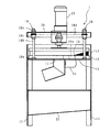
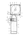
本発明の一実施例に係る球体洗浄装置はゴルフボール洗浄装置に本発明を適用したものであり、図1の縦断側面図、図2の正面図及び図3の平面図に示すように、洗浄装置本体1と、球体供給装置3と、球体供給装置3から洗浄装置本体1にゴルフボールからなる球体4(図2に示す。)を導くシュート2とを備えている。
【0033】
洗浄装置本体1は、4本の脚11に支持された水平平板状の受球部材12と、この受球部材12の上面にゴルフボールからなる球体4の直径よりも少し小さい所定の間隔を置いて対向し、かつ、受球部材12の面方向に毛先が移動するように配置された端面ブラシからなる洗浄ブラシ13と、この洗浄ブラシ13に対向させて、該洗浄ブラシ13の毛先よりも速い速度で毛先が移動する追込ブラシ14とを備える。
【0034】
受球部材12の上面には、洗浄ブラシ13の外径とほぼ同径の円弧状の周壁15が立設され、この周壁15の一部分を切欠くことにより、受球部材12、洗浄ブラシ13及び周壁15により区画される空間に球体4を供給する入口16が開設される。又、受球部材12の中央部には洗浄された球体4を受球部材12、洗浄ブラシ13及び周壁15により区画される空間から排出する出口17が開設される。
【0035】
前記入口16は、シュート2から転げ込む球体を洗浄ブラシ13にその法線に対して傾斜する方向に案内する入口ガイド16aを備え、この入口ガイド16aで球体を洗浄ブラシ13の外周にその回転方向に逆らわずに斜め方向から転げ込むように案内することにより、球体が洗浄ブラシ13の外周で弾き返されることなく、受球部材12と洗浄ブラシ13との間の空間に転がり込むようになる。
【0036】
前記洗浄ブラシ14は、4本の支柱装置18を介して受球部材12に支持させた天板19の中央部に縦軸心周りに回転可能に支持され、モータ20により一方向、例えば図3において時計周り方向に駆動される。
【0037】
なお、各支柱装置18は受球部材12に固定されたナット18aと、これに螺合されたネジ軸からなる支柱18bと、この支柱18bに固定され、前記天板19の隅部を支承するスプロケット18cとを備え、各支柱装置18のスプロケット18cにわたってエンドレスチェーン18dを巻き掛けることにより、各支柱装置18のスプロケット18c及び支柱18bを同期して回転させ、各支柱装置18のスプロケット18cに支承された天板19を上下に平行移動させるようにしている。
【0038】
又、各支柱18bはスプロケット18cよりも上側に延長され、前記天板19の隅部を貫通して、その上側に突出するようにしている。そして、各支柱装置18のスプロケット18c及び支柱18bを同期して回転させることにより球体4の直径に対応して受球部材12に対する天板19及び洗浄ブラシ13の高さを調整した後、この支柱18bの上端部に螺合した固定用ナット18eを締め込むことにより、天板19及び洗浄ブラシ13を受球部材12に対して調整した高さに固定できるようにしている。
【0039】
ところで、前記追込ブラシ14は、前記入口16よりも洗浄ブラシ13の回転方向下手側で、前記入口16にできるだけ近い位置に配置され、洗浄ブラシ13の径方向に平行な水平軸心回りに回転可能に設けられるた周面ブラシで構成され、その上周部を受球部材12上に露出させてある。そして、この追込ブラシ14は、前記脚11に支持させたモータ21により、その上周部において、前記洗浄ブラシ13の毛先が移動する方向と同じ方向に、該洗浄ブラシ13の毛先よりも速い速度で毛先が移動するように駆動される。
【0040】
この追込ブラシ14は、シュート2を転がり下りる勢いの余りで入口16からこの追込ブラシ14のところまで自然に転がり込んだ球体4をこの追込ブラシ14と洗浄ブラシ13との間にくわえ込み、勢い付けて確実に洗浄ブラシ13と受球部材12との間の空間に送り込む。
【0041】
入口16から洗浄ブラシ13と受球部材12との間の空間に多数の球体4が順次送り込まれると、先に送り込まれた球体4は洗浄ブラシ13によってその回転方向に転がされながら、後から送り込まれた球体4に押されて次第に洗浄ブラシ13の中央部に移動し、前記出口17から下方に落下し、回収ケース23に回収される。
【0042】
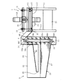
前記球体供給装置3は、エレベータ室31と、その一横側で上下に重なるように配置されたホッパー32及び洗浄液室33とを備え、前記ホッパー32は一度に多量の球体4を受け入れるために、全面的に開放された上面34と、エレベータ室31と反対側で低くなる片流れ傾斜底面35と、この片流れ傾斜底面35の傾斜先端に開口する落球口36と有している。又、洗浄液室33はエレベータ室31側で低くなる片流れ傾斜底面37を有しており、エレベータ室31と反対側でホッパー32の落球口36から落下した球体4がこの片流れ傾斜底面37上を転がってエレベータ室31に向かうようにしてある。
【0043】
洗浄液室33及びエレベータ室31には所定量の洗浄液が貯留されているので、球体4が洗浄液室33の片流れ傾斜底面37上を転がってエレベータ室31に向かう間に球体4の表面に洗浄液が付着することになる。
【0044】
エレベータ室31内にはエレベータ室31に転がって来た球体4を拾い上げ、ホッパー32の上面よりも高い位置まで持ち上げ、このホッパー32の上面よりも高い位置でシュート2に放出するエレベータ38が配置される。
【0045】
このエレベータ38は、エレベータ室31内に上下に適当な間隔を置いて平行に配置された1対の回転軸38a、38bと、各回転軸38a、38bの両端部に固定されたスプロケット38c、38dと、上下対をなすスプロケット38c、38dに巻き掛けられた1対のチェーン38eと、これら対をなすチェーン38eに所定のピッチを置いて連結された櫛歯状のラック38fと、エレベータ室31外に配置され、上側の回転軸38aを駆動するモータ38gとを備える。
【0046】
又、エレベータ室31の下部には、洗浄液室33の片流れ傾斜底面37に連続させた櫛歯状の捕球ガイド39が設けられ、洗浄液室33の片流れ傾斜底面37を転がってエレベータ室31に入った球体4が確実にラック38fにすくい上げられるようにしている。
【0047】
ラック38fにすくい上げられた球体4はエレベータ室31内の上部でラック38fが反転することによりシュート2に放出される。このラック38fから放出される球体4を確実にシュート2に導くために、エレベータ室31内の上部には櫛歯状の放出ガイド40が設けられる。
【0048】
エレベータ38から放出された球体4は、シュート2に案内されて洗浄装置本体1の入球口16に向かい、この入球口16から周壁15、受球部材12及び洗浄ブラシ13で区画される空間内に転がり込む。そして、洗浄ブラシ13の毛先に捕らえられてこの空間内を移動し、やがて、洗浄ブラシ13と追込ブラシ14との間に挟み込まれる。
【0049】
洗浄ブラシ13の毛先と追込ブラシ14の上周部の毛先とは同じ方向に移動しているので、球体4は殆ど抵抗を受けることなく洗浄ブラシ13と追込ブラシ14との間に挟み込まれるが、洗浄ブラシ13の毛先の移動速度が追込ブラシ14の上周部の毛先の移動速度よりも速いので、球体4には球体4の上側が洗浄ブラシ13の毛先の移動方向に進む方向の回転力が与えられ、この回転力により、球体4はその上側が洗浄ブラシ13の毛先の移動方向に進む方向の自転を始めることになる。そして、この球体4の自転は洗浄ブラシ13の回転によって助長されるので、球体4が追込ブラシ14を乗り超えた後にも球体4の自転がある程度続く。そして、球体4が自転することにより、球体4の表面全体が万遍なく洗浄ブラシ13と擦れ合って、或いは、これに加えて追込ブラシ14と擦れ合って、効率良くブラッシングされながら洗浄されることになる。その結果、球体4の表面の一部分の洗浄が不十分になることを確実に防止することができ、球体4の表面全体を効率良く洗浄できるようになるのである。
【0050】
なお、この洗浄装置本体1においては、入球口16の上手側の周壁15の端部15aを洗浄ブラシ13の回転軸心に向かって進退調整できるようにしてあり、入球口16から周壁15、受球部材12及び洗浄ブラシ13で区画される空間内に転がり込む球体4の量が少ない場合には入球口16の上手側の周壁15の端部15aを洗浄ブラシ13の回転軸心に向かって進め、多い場合には入球口16の上手側の周壁15の端部15aを洗浄ブラシ13の回転軸心から遠ざけるようにしている。
【0051】
又、この洗浄装置本体1においては、周壁15、受球部材12及び洗浄ブラシ13で区画される空間に連通する液供給管41が設けられ、必要に応じてこの液供給管41を介して洗浄液或いは水を該空間内に供給できるようにしている。
【0052】
【発明の効果】
以上に説明したように、本発明の球体洗浄装置は、円板状の基体の端面に植毛した端面ブラシからなる洗浄ブラシを用い、この洗浄ブラシの毛先から所定の間隔を置いて配置される平板からなる受球部材とを設けるので、これら洗浄ブラシと受球部材との間に球体を挿んで洗浄ブラシを回転さることにより球体を受球部材の上で転がしながら洗浄ブラシで洗浄ないし琢磨できるうえ、複雑な形状の螺旋ガイドが不要になり、又、円筒形の洗浄槽に代わって形状が単純な平板状の受球部材を設ければよいので、大幅なコストダウンを図ることができる。
【0053】
又、本発明は、洗浄ブラシと受球部材との間の空間の周囲を取り囲む周壁を設けるで、入口から洗浄ブラシと受球部材との間の空間に入れた球体がその空間から飛び出すことが防止され、入口から洗浄ブラシと受球部材との間の空間に入れた球体が確実に洗浄ないし琢磨される上、この周壁の一部を切欠いて入口を形成し、洗浄ブラシの中央部に対向させて受球部材に出口を開設するので、洗浄ブラシと受球部材との間の空間に球体を導入する入口(又は出口)を洗浄ブラシの中央部に設ける必要がなくなり、洗浄ブラシの形状及び洗浄ブラシの支持構造を簡単にして、一層大幅なコストダウンを図ることができる。
【0054】
更に、本発明は、前記入口から洗浄ブラシと受球部材との間の空間に導入される球体を洗浄ブラシの法線に対して傾斜する方向で導入する入口ガイドが設けられるので、入口から洗浄ブラシと受球部材との間の空間に球体を洗浄ブラシの法線方向に導入する時に比べて、洗浄ブラシの回転によって球体が弾かれ難くなり、球体を円滑に入口から洗浄ブラシと受球部材との間の空間に導入できるようになり、入口に供給された球体を確実に洗浄ブラシと受球部材との間の空間に導入して洗浄できる。
【0055】
加えて、本発明は、前記洗浄ブラシに対向させて、該洗浄ブラシの毛先よりも速い速度で毛先が移動する追込ブラシが設けられるので、入口から洗浄ブラシと受球部材との間の空間に導入された球体が、追込ブラシによって洗浄ブラシと追込ブラシとの間に引き込んで挟まれた後、確実に洗浄ブラシと受球部材との間の空間に送り込まれ、一層確実に洗浄されるようになるのである。
【0056】
要するに、本発明の球体洗浄装置によれば、多量の球体を効率良く洗浄ないし琢磨することができる上、部品の形状が簡単で、安価に構成できるのである。
【図面の簡単な説明】
【図1】本発明の縦断側面図である。
【図2】本発明の正面図である。
【図3】本発明の平面図である。
【符号の説明】
3 球体供給装置
4 球体
12 受球部材
13 洗浄ブラシ
14 追込ブラシ
15 周壁
16 入口
16a 入口ガイド
17 出口
32 ホッパー
33 洗浄液室
38 エレベータ[0001]
BACKGROUND OF THE INVENTION
The present invention relates to a sphere cleaning device for cleaning golf balls, baseballs, and the like, and a sphere polishing device for polishing golf balls, baseballs, etc. In particular, a large amount of spheres can be efficiently cleaned or polished. The present invention relates to a spherical body cleaning device that has a simple shape and can be configured at low cost.
[0002]
[Prior art]
In a golf driving range or a batting center, it is necessary to efficiently wash or polish a large number of repeatedly used training balls.
[0003]
Conventionally, for cleaning the practice balls, a sphere cleaning device is used in which the cleaning liquid and the practice balls are put into a cleaning tank containing a brush, and the brushes are rotated to stir the cleaning liquid and the practice balls.
[0004]
For example, JP-A-6-292742 discloses a rotating brush driven by a motor in a box-shaped frame (cleaning tank), and a stopper that supports the ball in the cleaning tank so as to be partially immersed in the cleaning liquid. And a ball cleaner having guide means for pressing the ball supported by the stopper against the rotating brush.
[0005]
Japanese Patent Application Laid-Open No. 7-1000022 includes a cylindrical cleaning tank filled with a cleaning liquid and a cleaning brush made of a peripheral brush planted on the peripheral surface, and a spiral guide provided along the inner surface of the cleaning tank; The other end side of the cleaning tank while the spherical body introduced into the cleaning tank from the inlet formed at one end of the cleaning tank is brought into contact with the inner surface of the cleaning tank with a cleaning brush with a spiral guide as a guide The spherical body washing | cleaning apparatus which was sent to No. 2 and discharged | emitted from the exit formed in the other end part of this washing tank is described.
[0006]
[Problems to be solved by the invention]
The ball washer described in JP-A-6-292742 is provided for a player to wash a game ball during a game, and is not suitable for washing a large number of balls.
[0007]
In addition, according to the sphere cleaning apparatus described in the above-mentioned JP-A-7-100289, a large amount of spheres can be continuously cleaned by successively introducing spheres into one end of the cleaning tank. Since the spiral guide having a complicated part shape is provided, there is a problem that it is expensive.
[0008]
The sphere cleaning device according to the present invention is made in view of such circumstances, and an object thereof is to provide a sphere cleaning device that can efficiently clean a large amount of spheres at a low price.
[0009]
[Means for Solving the Problems]
In order to achieve this object, the present invention first uses a cleaning brush comprising an end surface brush planted on the end surface of a disk-shaped substrate, and is a flat plate disposed at a predetermined interval from the tip of the cleaning brush. The technical means of providing a ball receiving member made of is adopted.
[0010]
If the ball is inserted between the cleaning brush and the ball receiving member and the cleaning brush is rotated, the ball can be cleaned or polished with the cleaning brush while rolling the ball on the ball receiving member. A spiral guide having a simple shape is not necessary, and a flat ball receiving member having a simple shape may be provided in place of the cylindrical cleaning tank, so that a significant cost reduction can be achieved.
[0011]
Further, the present invention provides a peripheral wall surrounding the periphery of the space between the cleaning brush and the ball receiving member, and an inlet formed by cutting out a part of the peripheral wall, and a central portion of the cleaning brush. And an outlet opened in the ball receiving member.
[0012]
By providing the peripheral wall in this way, the sphere put in the space between the cleaning brush and the ball receiving member from the entrance is prevented from jumping out of the space, and the space between the cleaning brush and the ball receiving member is introduced from the entrance. The inserted sphere is reliably cleaned or polished.
[0013]
In addition, a part of the peripheral wall is notched to form an inlet, and an outlet is opened in the ball receiving member so as to face the central portion of the cleaning brush, so that a sphere is introduced into the space between the cleaning brush and the ball receiving member. There is no need to provide an inlet (or outlet) at the center of the cleaning brush, the shape of the cleaning brush and the support structure of the cleaning brush can be simplified, and the cost can be further greatly reduced.
[0014]
Furthermore, the present invention provides a technical means that an inlet guide is provided for introducing a sphere introduced from the inlet into a space between the cleaning brush and the ball receiving member in a direction inclined with respect to the normal line of the cleaning brush. Is adopted.
[0015]
As a result, compared with the case where the sphere is introduced in the normal direction of the cleaning brush from the entrance to the space between the cleaning brush and the ball receiving member, the sphere is less likely to be repelled by the rotation of the cleaning brush, and the sphere is smoothly removed from the entrance. It becomes possible to introduce into the space between the cleaning brush and the ball receiving member.
[0016]
In addition, the present invention employs a technical means in which an additional brush is provided opposite to the cleaning brush so that the tip of the hair moves at a faster speed than the tip of the cleaning brush.
[0017]
As a result, the sphere introduced into the space between the cleaning brush and the ball receiving member from the entrance is pulled and sandwiched between the cleaning brush and the additional brush by the additional brush, and then securely received by the cleaning brush and the receiving brush. It is fed into the space between the ball members and is surely cleaned.
[0018]
The follow-up brush of the present invention may be provided so as to face the entire surface of the cleaning brush, but a sphere is sandwiched between the cleaning brush and the cleaning brush and the ball receiving member is forcibly disposed. It is sufficient to provide a part of the cleaning brush so as to exert the feeding function, and it is advantageous in terms of cost to provide the part facing the part of the cleaning brush. As a follow-up brush provided to face a part of the cleaning brush, in order to exert a function of forcing the sphere between the cleaning brush and the ball receiving member by sandwiching the sphere between this and the cleaning brush, A circumferential brush that rotates about an axis parallel to the end face of the cleaning brush is used.
[0019]
In addition, the material of the hair of the cleaning brush and the additional brush of the present invention is not particularly limited, and for example, organic fibers such as plant fibers, animal fibers, and synthetic fibers, and inorganic fibers such as metal fibers and ceramic fibers may be used. Is possible.
[0020]
Moreover, the length of the bristle of the cleaning brush and the additional brush of the present invention, the flocking density and the like are not particularly limited, and may be appropriately selected in consideration of the rigidity or flexibility of the hair material used.
[0021]
Further, the cleaning brush and the follow-up brush of the present invention include those using a sponge or buff instead of the hair.
[0022]
By the way, in the sphere cleaning apparatus of the present invention, the supply of the sphere between the ball receiving member and the cleaning brush may be performed manually, but a large number of spheres can be input at a time, It is preferable to provide a spherical body supply device that is appropriately divided and supplied between the ball receiving member and the cleaning brush.
[0023]
As this sphere supply device, a simple lower hopper may be used. However, in order to attach the cleaning liquid to the sphere immediately before being supplied between the ball receiving member and the cleaning brush, the cleaning liquid is placed below the hopper. It is preferable to provide a cleaning liquid chamber for storing the sphere so that the sphere falling from the hopper is immersed in the cleaning liquid in the cleaning liquid chamber.
[0024]
In this case, providing the hopper and the cleaning liquid chamber so as to overlap each other is advantageous because the configuration can be simplified and the laying area can be reduced.
[0025]
In this case, since at least a part of the sphere sinks below the surface of the cleaning liquid, an elevator may be provided to scoop up the sphere from the cleaning liquid and supply it to the entrance in order to eliminate the flow of the cleaning liquid. preferable.
[0026]
Of course, it is not essential for the present invention to attach the cleaning liquid to the sphere immediately before being supplied between the ball receiving member and the cleaning brush, and means for supplying the cleaning liquid to the space between the ball receiving member and the cleaning brush. The cleaning liquid may be attached to the sphere fed into the space between the ball receiving member and the cleaning brush while being dried.
[0027]
Alternatively, the cleaning liquid may be attached to the sphere in advance using a sphere supply device, and the cleaning liquid may be rinsed off by applying water to the sphere fed into the space between the ball receiving member and the cleaning brush.
[0028]
In the present invention, the cleaning liquid includes a liquid not containing a detergent, a detergent solution, and a detergent stock solution, and water is typically used as the liquid not containing the detergent. The detergent solution includes those using water as a solvent and those using other solvents, and the detergent includes an alkaline detergent, an acidic detergent, and a neutral detergent.
[0029]
By the way, in the sphere cleaning apparatus of the present invention, the sphere may be so-called dry wiped without using the cleaning liquid. Including this case, when the cleaning liquid is not used in the sphere cleaning device of the present invention, the treatment performed by the sphere cleaning device is more suitable than polishing. Accordingly, the present invention may be referred to as a spherical polishing device, particularly when no cleaning liquid is used.
[0030]
When polishing the spheres according to the present invention, so-called polishing materials may be used. Examples of the polishing materials include natural polishing materials such as clays represented by dolomite, cinnabar, talc, and microcrystalline anhydrous silicic acid. And artificial polishing materials such as iron oxide, chromium oxide, cesium oxide, calcined alumina, calcined dolomite, glass powder, and other fine powders of high hardness substances. This polishing material is often in the form of a dry powder, but it can be used in the form of a powder with moderate humidity, or even if this polishing material is mixed with water or other solvent and used in a liquid form. Good.
[0031]
DETAILED DESCRIPTION OF THE INVENTION
A spherical body cleaning apparatus according to an embodiment of the present invention will be described below with reference to the drawings.
[0032]
A spherical body cleaning apparatus according to an embodiment of the present invention is an application of the present invention to a golf ball cleaning apparatus. As shown in a longitudinal side view of FIG. 1, a front view of FIG. 2, and a plan view of FIG. An apparatus
[0033]
The cleaning device
[0034]
On the upper surface of the
[0035]
The
[0036]
The cleaning
[0037]
Each
[0038]
Each support 18b extends upward from the
[0039]
By the way, the follow-up
[0040]
The push-in
[0041]
When a large number of
[0042]
The
[0043]
Since a predetermined amount of cleaning liquid is stored in the cleaning
[0044]
An
[0045]
The
[0046]
A comb-shaped
[0047]
The
[0048]
The
[0049]
Since the bristles of the cleaning
[0050]
In this
[0051]
Further, in the cleaning apparatus
[0052]
【The invention's effect】
As described above, the spherical body cleaning device of the present invention uses a cleaning brush composed of an end surface brush planted on the end surface of a disk-shaped substrate, and is arranged at a predetermined interval from the tip of the cleaning brush. Since the ball receiving member made of a flat plate is provided, the ball can be washed or polished with the cleaning brush while rolling on the ball receiving member by inserting the sphere between the cleaning brush and the ball receiving member and rotating the cleaning brush. In addition, a spiral guide having a complicated shape is not required, and a flat ball receiving member having a simple shape may be provided in place of the cylindrical cleaning tank, so that a significant cost reduction can be achieved.
[0053]
Further, the present invention provides a peripheral wall surrounding the periphery of the space between the cleaning brush and the ball receiving member, so that the sphere placed in the space between the cleaning brush and the ball receiving member can jump out of the space from the entrance. The sphere inserted into the space between the cleaning brush and the ball receiving member from the inlet is reliably cleaned or polished, and a part of this peripheral wall is cut away to form the inlet and face the center of the cleaning brush Since the outlet is opened in the ball receiving member, it is not necessary to provide an inlet (or outlet) for introducing a sphere into the space between the cleaning brush and the ball receiving member in the central portion of the cleaning brush. The support structure of the cleaning brush can be simplified, and the cost can be greatly reduced.
[0054]
Furthermore, the present invention is provided with an inlet guide for introducing a sphere introduced into the space between the cleaning brush and the ball receiving member from the inlet in a direction inclined with respect to the normal line of the cleaning brush. Compared to the case where the sphere is introduced in the normal direction of the cleaning brush into the space between the brush and the ball receiving member, the sphere is less likely to be repelled by the rotation of the cleaning brush, and the sphere is smoothly moved from the entrance to the cleaning brush and the ball receiving member. The sphere supplied to the inlet can be reliably introduced into the space between the cleaning brush and the ball receiving member and cleaned.
[0055]
In addition, the present invention is provided with a push-in brush that is opposed to the cleaning brush and moves at a faster speed than the tip of the cleaning brush. After the sphere introduced into the space is drawn and sandwiched between the cleaning brush and the additional brush by the additional brush, it is surely sent into the space between the cleaning brush and the ball receiving member, and more reliably It will be washed.
[0056]
In short, according to the sphere cleaning device of the present invention, a large amount of spheres can be efficiently cleaned or polished, and the shape of the parts can be simple and inexpensive.
[Brief description of the drawings]
FIG. 1 is a longitudinal side view of the present invention.
FIG. 2 is a front view of the present invention.
FIG. 3 is a plan view of the present invention.
[Explanation of symbols]
3 spherical
Claims (3)
Priority Applications (1)
| Application Number | Priority Date | Filing Date | Title |
|---|---|---|---|
| JP08543499A JP4046885B2 (en) | 1999-03-29 | 1999-03-29 | Sphere cleaning device |
Applications Claiming Priority (1)
| Application Number | Priority Date | Filing Date | Title |
|---|---|---|---|
| JP08543499A JP4046885B2 (en) | 1999-03-29 | 1999-03-29 | Sphere cleaning device |
Publications (2)
| Publication Number | Publication Date |
|---|---|
| JP2000271252A JP2000271252A (en) | 2000-10-03 |
| JP4046885B2 true JP4046885B2 (en) | 2008-02-13 |
Family
ID=13858758
Family Applications (1)
| Application Number | Title | Priority Date | Filing Date |
|---|---|---|---|
| JP08543499A Expired - Fee Related JP4046885B2 (en) | 1999-03-29 | 1999-03-29 | Sphere cleaning device |
Country Status (1)
| Country | Link |
|---|---|
| JP (1) | JP4046885B2 (en) |
Families Citing this family (4)
| Publication number | Priority date | Publication date | Assignee | Title |
|---|---|---|---|---|
| JP4719663B2 (en) * | 2006-11-30 | 2011-07-06 | 有限会社テクノ | Golf ball cleaning equipment |
| SE532447C2 (en) * | 2007-03-14 | 2010-01-19 | Range Servant Ab | Golf ball cleaning device |
| DE102009014006A1 (en) * | 2009-03-19 | 2010-09-23 | Sms Siemag Aktiengesellschaft | Method and device for cleaning a metal strip |
| CN118162407B (en) * | 2024-04-10 | 2026-02-06 | 常州冠为智能科技有限公司 | Surface cleaning device for Kegel ball processing |
-
1999
- 1999-03-29 JP JP08543499A patent/JP4046885B2/en not_active Expired - Fee Related
Also Published As
| Publication number | Publication date |
|---|---|
| JP2000271252A (en) | 2000-10-03 |
Similar Documents
| Publication | Publication Date | Title |
|---|---|---|
| US5353822A (en) | Apparatus and method for washing balls | |
| CN109310259A (en) | Wet cleaning equipment with cleaning rollers that can rotate around the roller axis | |
| JP4046885B2 (en) | Sphere cleaning device | |
| US4970746A (en) | Golf ball washer | |
| CN109048644A (en) | The processing unit and processing method of wafer, chemical-mechanical polishing system | |
| US4805251A (en) | Golf ball washer | |
| JP2001070905A (en) | Ball washer | |
| US5819351A (en) | Ball cleaning and waxing machine | |
| KR930006788B1 (en) | Washing machine | |
| SE468787B (en) | DEVICE FOR TREATMENT OF CIRCULAR GOODS, eg WASHING OF GOLF BALLS | |
| KR200449007Y1 (en) | Golf ball automatic cleaning device | |
| US2931058A (en) | Golf ball washing machine | |
| JPS59196758A (en) | Washing method for pellet to be used in washer for pachinko game machine | |
| JPH07100229A (en) | Spherical body washing device | |
| JP3194221B2 (en) | Accessory cleaning equipment | |
| JP3490634B2 (en) | Game media polishing machine | |
| JPH0718752U (en) | Golf ball cleaning machine and golf ball cleaning apparatus using the same | |
| US3802448A (en) | Permanent wave hair roller washer | |
| JPH08299501A (en) | Golf ball washing device | |
| JP2002186772A (en) | Pachinko ball cleaning equipment | |
| JPH09182815A (en) | Washing device for golf ball | |
| AU618397B2 (en) | Apparatus for cleaning discrete articles | |
| JP3133191B2 (en) | Ball washer | |
| US784662A (en) | Ball-cleaning device. | |
| WO1990001379A1 (en) | Apparatus for cleaning discrete articles |
Legal Events
| Date | Code | Title | Description |
|---|---|---|---|
| A621 | Written request for application examination |
Free format text: JAPANESE INTERMEDIATE CODE: A621 Effective date: 20051206 |
|
| TRDD | Decision of grant or rejection written | ||
| A01 | Written decision to grant a patent or to grant a registration (utility model) |
Free format text: JAPANESE INTERMEDIATE CODE: A01 Effective date: 20071024 |
|
| A977 | Report on retrieval |
Free format text: JAPANESE INTERMEDIATE CODE: A971007 Effective date: 20071025 |
|
| A61 | First payment of annual fees (during grant procedure) |
Free format text: JAPANESE INTERMEDIATE CODE: A61 Effective date: 20071121 |
|
| FPAY | Renewal fee payment (event date is renewal date of database) |
Free format text: PAYMENT UNTIL: 20101130 Year of fee payment: 3 |
|
| R150 | Certificate of patent or registration of utility model |
Free format text: JAPANESE INTERMEDIATE CODE: R150 |
|
| FPAY | Renewal fee payment (event date is renewal date of database) |
Free format text: PAYMENT UNTIL: 20101130 Year of fee payment: 3 |
|
| FPAY | Renewal fee payment (event date is renewal date of database) |
Free format text: PAYMENT UNTIL: 20131130 Year of fee payment: 6 |
|
| LAPS | Cancellation because of no payment of annual fees |