JP4046863B2 - X-ray generator with X-ray tube - Google Patents
X-ray generator with X-ray tube Download PDFInfo
- Publication number
- JP4046863B2 JP4046863B2 JP24167198A JP24167198A JP4046863B2 JP 4046863 B2 JP4046863 B2 JP 4046863B2 JP 24167198 A JP24167198 A JP 24167198A JP 24167198 A JP24167198 A JP 24167198A JP 4046863 B2 JP4046863 B2 JP 4046863B2
- Authority
- JP
- Japan
- Prior art keywords
- output window
- ray
- ray tube
- partition
- case
- Prior art date
- Legal status (The legal status is an assumption and is not a legal conclusion. Google has not performed a legal analysis and makes no representation as to the accuracy of the status listed.)
- Expired - Fee Related
Links
- 238000005192 partition Methods 0.000 claims description 50
- 238000010894 electron beam technology Methods 0.000 claims description 9
- 230000001681 protective effect Effects 0.000 description 26
- 239000000835 fiber Substances 0.000 description 10
- 239000000463 material Substances 0.000 description 8
- 239000011347 resin Substances 0.000 description 7
- 229920005989 resin Polymers 0.000 description 7
- 229910052782 aluminium Inorganic materials 0.000 description 5
- XAGFODPZIPBFFR-UHFFFAOYSA-N aluminium Chemical compound [Al] XAGFODPZIPBFFR-UHFFFAOYSA-N 0.000 description 5
- 230000002238 attenuated effect Effects 0.000 description 4
- WABPQHHGFIMREM-UHFFFAOYSA-N lead(0) Chemical compound [Pb] WABPQHHGFIMREM-UHFFFAOYSA-N 0.000 description 4
- 230000002093 peripheral effect Effects 0.000 description 4
- 229910001220 stainless steel Inorganic materials 0.000 description 4
- 239000010935 stainless steel Substances 0.000 description 4
- 230000000694 effects Effects 0.000 description 3
- 229910000833 kovar Inorganic materials 0.000 description 3
- 229920003023 plastic Polymers 0.000 description 3
- 239000004033 plastic Substances 0.000 description 3
- 229910052790 beryllium Inorganic materials 0.000 description 2
- ATBAMAFKBVZNFJ-UHFFFAOYSA-N beryllium atom Chemical compound [Be] ATBAMAFKBVZNFJ-UHFFFAOYSA-N 0.000 description 2
- 238000005530 etching Methods 0.000 description 2
- 230000017525 heat dissipation Effects 0.000 description 2
- 229910052751 metal Inorganic materials 0.000 description 2
- 239000002184 metal Substances 0.000 description 2
- 230000001012 protector Effects 0.000 description 2
- 238000004846 x-ray emission Methods 0.000 description 2
- XUIMIQQOPSSXEZ-UHFFFAOYSA-N Silicon Chemical compound [Si] XUIMIQQOPSSXEZ-UHFFFAOYSA-N 0.000 description 1
- 229910000831 Steel Inorganic materials 0.000 description 1
- 239000011248 coating agent Substances 0.000 description 1
- 238000000576 coating method Methods 0.000 description 1
- 230000007423 decrease Effects 0.000 description 1
- 229920001971 elastomer Polymers 0.000 description 1
- 230000005611 electricity Effects 0.000 description 1
- 239000011521 glass Substances 0.000 description 1
- 230000004048 modification Effects 0.000 description 1
- 238000012986 modification Methods 0.000 description 1
- 230000005855 radiation Effects 0.000 description 1
- 230000000191 radiation effect Effects 0.000 description 1
- 230000003014 reinforcing effect Effects 0.000 description 1
- 229910052710 silicon Inorganic materials 0.000 description 1
- 239000010703 silicon Substances 0.000 description 1
- 229920002379 silicone rubber Polymers 0.000 description 1
- 230000003068 static effect Effects 0.000 description 1
- 239000010959 steel Substances 0.000 description 1
- 239000013077 target material Substances 0.000 description 1
- 229920002803 thermoplastic polyurethane Polymers 0.000 description 1
Images
Landscapes
- X-Ray Techniques (AREA)
Description
【0001】
【発明の属する技術分野】
本発明は、X線管を備えるX線発生装置に関するものである。
【0002】
【従来の技術】
従来のX線発生装置の一例として、特開平10−106463号公報に記載されるものがある。この公報に開示されたX線発生装置は、保護ケース内にX線管を収容しており、このX線管においては、フィラメントが通電により熱せられると、電子ビームが放出され、電子ビームは加速されてターゲットに高速で衝突する。このとき、ターゲットからは、ターゲットを固着した出力窓を通して、ターゲットの材料に固有のX線が放射される。ここで、出力窓は、薄板状のベリリウム等からなり、わずかな損傷でX線管全体が使用できなくなる場合がある。このため、出力窓が出力窓保持部の内部に固定され、これにより出力窓の表面に対する損傷防止が図られている。
【0003】
【発明が解決しようとする課題】
このように従来のX線発生装置において、出力窓の損傷防止策がとられているが、出力窓の表面に損傷が与えられる可能性を少しでも低減させて出力窓の損傷をより確実に防止することが、使用者の安心感を高める上で望ましい。
【0004】
そこで、本発明は、X線強度の減衰を抑えつつ、出力窓の損傷をより確実に防止することができるX線管を備えたX線発生装置を提供することを目的とする。
【0005】
【課題を解決するための手段】
本発明者らは、出力窓の損傷をより確実に防止すべく、出力窓のX線出射方向に保護体を配置することを見出した。保護体としては、種々のものが考えられるが、本発明者らは、保護体として樹脂等を用い、この樹脂を出力窓の表面にコーティングすることを検討した。しかし、この場合、樹脂により出力窓の損傷は防止されるものの、X線が樹脂を通過することでその強度が大きく減衰すると共に、樹脂がX線の照射により変質してしまうこともある。そこで、本発明者らは、鋭意検討した結果、保護体として特定の構造を採用することで、上記目的を達成できることを見い出した。
【0012】
すなわち、本発明のX線発生装置は、開口端を有し、内部にカソードを有するバルブ、バルブの開口端側に配置される出力窓、バルブの開口端に設けられ、出力窓を保持する出力窓保持部、及び出力窓のバルブ側の内面に設けられ、カソードから放出される電子ビームの照射により発生するX線を出力窓を通して出射するターゲットを備えるX線管と、X線管のカソードとターゲットとの間に電圧を供給する電源部と、X線管及び電源部を内部に収容するケースとを備えるX線発生装置であって、ケースには、X線管の出力窓の外面側であって出力窓に対向する位置に、出力窓から出射されるX線を通過させるための複数の開口を画成する仕切り部が設けられていることを特徴とする。
【0013】
この構成によれば、電源部によりカソードとターゲットとの間に電圧が供給されると、カソードからターゲットに向けて電子ビームが照射され、ターゲットでX線が発生し、このX線は、出力窓を通過して出力窓の外面側に出射される。このとき、X線は、仕切り部の開口を通過してX線管の外部に放射される。また、仕切り部により、使用者の指や突起物などの侵入の可能性が十分に低減される。
【0014】
また、本発明のX線発生装置においては、仕切り部は、ケースとX線管との間で挟持されていることが好ましい。この場合、X線管の作動中に、ターゲットで発生し続ける熱によりX線管が高温になる場合には、X線管の熱が仕切り部のみならずケースにも伝えられ、仕切り部及びケースの双方から放熱されることになる。
【0015】
【発明の実施の形態】
以下、図面と共に本発明のX線発生装置の好適な実施形態について詳細に説明する。
【0016】
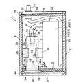
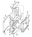
図1は、本実施形態に係るX線発生装置を示す断面図であり、図2は、X線発生装置の分解斜視図である。これら図面に示すX線発生装置1は、ボックスタイプからなる保護ケース2を有し、この保護ケース2は、熱伝導性の高い材料、例えばアルミニウムからなり、4分割されている。すなわち、図2に示すように、保護ケース2は、断面コ字状の上蓋3と断面コ字状の下蓋4と平板状の正面パネル5と平板状の背面パネル6とからなり、4分割型のボックスを構成している。また、上蓋3の前端及び後端には、正面パネル5及び背面パネル6の上端を差し込むためのパネル支持溝3a及び3bが形成され、下蓋4の前端及び後端には、正面パネル5及び背面パネル6の下端を差し込むためのパネル支持溝4a及び4bが形成されている。
【0017】
そこで、保護ケース2を組み立てる場合、補強板29の下側を下蓋4の内面にネジ固定した後、下蓋4のパネル支持溝4a,4bに正面パネル5及び背面パネル6の下端をそれぞれ差し込み、上蓋3のパネル支持溝3a,3bに正面パネル5及び背面パネル6の上端を上蓋3のパネル支持溝3a,3bに差し込むようにして、上蓋3と下蓋4とを合わせ、補強板29の上側を上蓋3の内面にネジ固定することで、下蓋4に対して上蓋3をしっかりと固定する。すなわち、保護ケース2は、正面パネル5及び背面パネル6を上蓋3と下蓋4とで挟み込む構造になっている。
【0018】
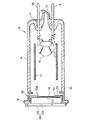
この保護ケース2内には、軟X線を発生させて静電気の除去等に利用されるX線管8が配置されている。このX線管8は、図3に示すように、コバールガラス製の円筒状バルブ9を有し、このバルブ9の末端には、排気管10をもったステム11が形成され、バルブ9の開口端50には、円筒状をなすコバール金属製の出力窓保持部12が融着接続されている。この出力窓保持部12は、内方に突出し中央開口12aを形成する着座部12bを有し、この着座部12bには、中央開口12aを塞ぐように円板状の出力窓13がAgろう付けにより固定されている。出力窓13のバルブ9側の内面13aには、電子ビームの衝突によりX線を発生させるターゲット14が蒸着されている。
【0019】
更に、ステム11には2本のステムピン15が固定され、バルブ9内には、所定の電圧で電子ビームを放出するカソードとしてのフィラメント16が設けられ、このフィラメント16は、ステムピン15の先端に固定されている。また、一方のステムピン15には、円筒状をなすステンレス製フォーカス17が固定されている。そして、この出力窓保持部12は、コバール金属からなるので、熱伝導性及び導電性をもち、アースされた保護ケース2に電気的に接続されることで接地電位となり、ターゲット14を接地電位にしている。
【0020】
ところで、X線管8に用いられる出力窓13は、薄板状のベリリウム(Be)からなり、わずかな損傷でX線管8を使用できなくなる場合がある。このため、円筒状の出力窓保持部12の内部に出力窓13が収容され、これにより出力窓13の表面に対して与えられる損傷の防止が図られている。しかしながら、出力窓13の表面に損傷が与えられる可能性を少しでも低減させて、出力窓13の損傷をより確実に防止することが、使用者の安心感を高める上で望ましい。
【0021】
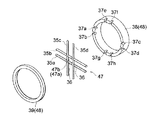
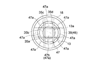
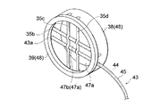
そこで、X線管8には、出力窓13を保護するための仕切り部47が設けられており、仕切り部47は、環状部48を介して出力窓保持部12のフランジ部18に接着固定されている。ここで、環状部48は、図4に示すように、フランジ部18に接着固定される環状の保持リング38と、保持リング38の周縁部に接着固定される環状の押えリング39とで構成され、仕切り部47は、この保持リング38と、押えリング39とによって挟持されている。仕切り部47は、出力窓13の外面側であって、出力窓13に対向する位置に配置されている(図5参照)。
【0022】
仕切り部47としては、図4に示すように、例えば格子状に組み立てられた線状部材35a〜35dが用いられる。この場合、平行に配置される線状部材35c,35dに対して、別の平行に配置した線状部材35a,35bが直交した状態で固定されている。なお、線状部材35a〜35dを相互にしっかりと固定するため、線状部材35c,35dにはそれぞれ2つずつ凹部36が形成されており、線状部材35a,35bを線状部材35a,35bに直交させた状態で、線状部材35a,35bがこれらの凹部36に収容されている。このように、線状部材35a〜35dを格子状に交差させることで、出力窓13から出射されるX線を通過させることができ、X線管8の外部から指や突起物が入り込む可能性を一層低減させることが可能となる。
【0023】
線状部材35a〜35dを構成する材料としては、放熱性及び熱伝導性の高い材料、例えばアルミニウムやステンレスなどが用いられる。また、線状部材35a〜35dのそれぞれの平均径は、0.1〜0.5mmであることが好ましい。線状部材35a〜35dのそれぞれの平均径が0.1mm未満では、線状部材35a〜35dの機械的強度が低下し、仕切り部47が破損しやすくなる傾向があり、0.5mmを超えると、X線が線状部材35a〜35dによって大きく減衰される傾向がある。
【0024】
仕切り部47は、環状部48の保持リング38と押さえリング39とによって挟持されている。ここで、図4に示すように、保持リング38の周縁部には、線状部材35a〜35dの各端部を収容するための8つの収容溝37a〜37hが形成され、線状部材35a〜35dの各端部が収容溝37a〜37hに嵌合されることで、線状部材35a〜35dが保持リング38に保持されている。また、保持リング38の周縁部には、環状の押えリング39が接着固定され、これにより線状部材35a〜35dが保持リング38から外れないようになっている。
【0025】
なお、保持リング38を構成する材料としては、出力窓13で発生した熱が出力窓保持部12を介して伝達されるよう導電性及び熱伝導性を有する材料、例えばアルミニウムやステンレスなどが用いられ、押えリング39を構成する材料としては、例えばアルミニウムやステンレスが用いられる。
【0026】
また、図5に示すように、保持リング38と押えリング39とで仕切り部47を挟持した場合、仕切り部47は、環状部48の内側に9個の開口47aを画成することになる。ここで、仕切り部47の中央には、中央開口47b(48a)が形成され、この中央開口47bは、出力窓13の中央部13aに対向している。従って、出力窓13の中央部13aから出射される極大強度を有するX線が、線状部材35a〜35dによって減衰されることなく仕切り部47の開口47aを通過することとなり、X線管8から有用なX線を放射することができる。
【0027】
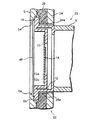
図6は、仕切り部47を固定した環状部48を有するX線管8を正面パネル5に取り付けた状態を示す断面図である。図6に示すように、フランジ部18は、ターゲット14に対して熱的及び電気的に導通状態にあるため、ターゲット14で発生し続ける熱により、出力窓保持部12が100℃前後の高温になり、フランジ部18が加熱されることになる。そこで、フランジ部18に伝えられる熱を逃すため、仕切り部47は、アルミ製の正面パネル5に接着固定され、フランジ部18も直接正面パネル5に接着固定されている。従って、仕切り部47は、保護ケース2の出力窓13に対向する位置に設けられると共に、保護ケース2とX線管8との間に挟持されることになる。なお、保護ケース2の正面パネル5には円形のX線照射口5aが設けられ、このX線照射口5aにX線管8の出力窓13を位置合わせすることで、保護ケース2内からのX線の放射を可能にしている。
ここで、正面パネル5において、X線照射口5aを形成する周縁部には、フランジ部18及び環状部48を収容させる環状の凹部5bが形成されている。従って、この凹部5bにフランジ部18及び環状部48を嵌め込むことで、正面パネル5に対するフランジ部18及び環状部48の着座性が良くなると同時に、X線管8の出力窓13と正面パネル5のX線照射口5aとの位置合わせを容易にすることができる。
【0028】
また、図1及び図2に示すように、保護ケース2内には、低電圧発生部19と高電圧発生部20とからなる電源部21が収容されている。この電源部21は、−9.5kVの高電位をステムピン15に供給して、フィラメント16とターゲット14との間に電圧を供給するためのものであり、先ず、低電圧発生部19で、−1kVまで電位を上げ、次に高電圧発生部20で−9.5kVまで電位を上げている。このような電源部21は、鋼製の電源ケース22に固定され、この電源ケース22には、電源部21を収容する部分とは別に、電源部21の側方でこれに隣接する位置にX線管8のバルブ9を収納するためのX線管収容部23が設けられている。
【0029】
図6に示すように、電源ケース22には、X線管収容部23の前端を形成し且つ正面パネル5に対して平行に対峙する保持板24が設けられ、この保持板24には、X線管8のバルブ9を挿入するための開口部24aが形成されている。そこで、この開口部24aにX線管8のバルブ9を挿入した場合、X線管8のフランジ部18は、保持板24の前面と正面パネル5の背面とで挟持される。この場合、電源ケース22は、保護ケース2の下蓋4にネジ固定されているので、X線管8のフランジ部18は、電源ケース22の保持板24と、保護ケース2のパネル支持溝3a,4aに固定された正面パネル5とでしっかり挟み付けられることになり、保護ケース2内でしっかりと固定される。ここで、保持板24と正面パネル5との間には、シリコンラバーからなる中間部材25が設けられている。この中間部材25は、保持板24と正面パネル5との間を略埋めるような形状を有すると共に、X線管8のバルブ9を挿入させるための開口部25aを有している。
【0030】
また、図1及び図2に示すように、X線管収容部23内には、X線管8を保護ケース2内で保持するための振れ止め部材26が設けられ、この振れ止め部材26は、ウレタン樹脂からなると共に、円弧状の押圧面26aでX線管8のバルブ9を挟み込むように2分割されている。そこで、保護ケース2の側壁に固定された保護板29と電源ケース22内の隔壁22aとに各振れ止め部材26を当接させ、円弧状の各押圧面26aでX線管8のバルブ9を挟み込むことで、X線管8を、保護ケース2内にしっかりと保持させることができる。
【0031】
なお、X線発生装置1は、電源部21の低電圧発生部19に所定の電圧を供給するための外部リード線31を有している。この外部リード線31はゴム製のキャップ30をもち、このキャップ30を背面パネル6の開口部6aに嵌め込むことで、外部リード線31は保護ケース2に固定される。また、高電圧発生部20にはカソード用リード線32が設けられ、このリード線32をX線管8のステムピン15に接続することで、−9.5kVの高電圧がフィラメント16に供給される。
【0032】
以上のような構成を有するX線発生装置1によれば、電源部21からX線管8のステムピン15に−9.5kVの高電位を供給し、フィラメント16から接地電位のターゲット14に向けて電子ビームを照射する。このとき、電子ビームの衝突によりターゲット14からX線が放射され、このX線が出力窓13を透過してX線管8の外部に出射される。このとき、X線は、仕切り部47の開口47aを通過するので、樹脂などを出力窓にコーティングする場合に比べてX線強度の減衰が抑えられる。ここで、仕切り部47の中央には、中央開口47bが形成され、この中央開口47bが出力窓13の中央部13aに対向する。このため、極大強度のX線が、線状部材35a〜35dによって減衰されることなく仕切り部47の開口47aを通過し、X線管8から有用なX線が出射されることになる。そして、X線発生装置1の作動中にフランジ部18で発生した熱は、環状部48及びフランジ部18が保護ケース2の正面パネル5に接触しているので、正面パネル5に伝えられて放熱されるだけでなく、環状部48の保持リング38を介して仕切り部47にも伝えられて、仕切り部47で放熱されることになる。従って、仕切り部47がない場合に比べて放熱効果が向上する。また、出力窓13が出力窓保持部12の内部に保持されているため使用者の指や突起物などが侵入しにくくなっている上に、仕切り部47により、使用者の指や突起物などが侵入する可能性が十分に低減され、出力窓13の損傷がより確実に防止されることになる。
【0033】
次に、第2の実施形態に係るX線発生装置について説明する。なお、前述したX線発生装置1と同一又は同等の構成については同一の符号を付し、その説明は省略する。
【0034】
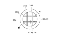
図7に示すように、本実施形態に係るX線発生装置40は、線状部材35a〜35dのうちの線状部材35aの表面にシンチレータ41を塗布した点で第1の実施形態に係るX線発生装置1と異なる。シンチレータ41としては、例えばZnSが用いられる。この場合、X線がシンチレータ41に照射されると、シンチレータ41が発光するため、X線の照射を目視で確認することができる。なお、シンチレータ41は、X線の放射が目視で確認できる限り、1本の線状部材35aに限定されず、もう1本の線状部材35bに塗布されてもよく、残り全ての線状部材35b,35c,35dに塗布されてもよい。
【0035】
次に、第3の実施形態に係るX線発生装置について説明する。なお、前述したX線発生装置1と同一又は同等の構成については同一の符号を付し、その説明は省略する。
【0036】
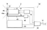
図8に示すように、本実施形態に係るX線発生装置42は、仕切り部47として、シンチレーションファイバ43の端部を有する点で第1又は第2実施形態に係るX線発生装置1,40と異なる。すなわち、図9に示すように、X線発生装置42においては、X線管8における線状部材35a〜35dのうちの1本の線状部材35aがシンチレーションファイバ43の一端部43aとなっている。ここで、シンチレーションファイバ43は、例えばプラスチックシンチレータからなるコア44と、コア44の外側に被覆されコア44よりも屈折率の低いプラスチック材料からなるクラッド45とで構成されるもの、又はプラスチックシンチレータ材料のみで構成されるものである。なお、X線発生装置42においては、シンチレーションファイバ43が、上述したように仕切り部47の一部を構成する場合、すなわち線状部材35aの代わりとして用いられる場合に限定されず、線状部材35a〜35dのいずれかの上に接着固定される場合も可能である。
【0037】
シンチレーションファイバ43は、長尺状となっており、その他端部43bには、例えばシリコンフォトダイオード等の光検出器46に接続されている。従って、X線がシンチレーションファイバ43の一端部43aに照射されると、シンチレーションファイバ43が発光してその光をコア44を通して導光し、その光が光検出器46で検出される。従って、検出される光強度に基づき、X線の強度変化を直接的にモニタすることができ、X線管8の寿命を検知することができる。
【0038】
なお、図8において、ターゲット14が高電圧発生部20に接続されており、ステムピン15が低電圧発生部19に接続されている。このため、ターゲット14が正の高電位となり、ステムピン15が低電位となり、フィラメント16とターゲット14との間で電位差が形成される。
【0039】
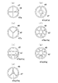
本発明は、前述した実施形態に限定されるものではなく、例えば、仕切り部47としては、格子状に構成された線状部材35a〜35dを環状部48で挟持したものに限らず、種々のものを用いることが可能である。例えば、仕切り部47と環状部48とをエッチングにより一体に形成することも可能である。この場合、エッチングにより形成された仕切り部47の形状は、円形の環状部48の内側に形成される仕切り部47により、複数の開口を画成するような形状となっている。仕切り部47の形状としては、例えば図10(a)〜(g)に示すものが用いられる。図10(a),(d)は、4つの開口47aを画成する仕切り部47、(b)は、3つの開口47aを画成する仕切り部47、(c),(g)は9つの開口47aを画成する仕切り部47、(e)は、5つの開口47aを画成する仕切り部47、(f)は7つの開口47aを画成する仕切り部47である。これらのうち、中央に開口47bを有することから、仕切り部47の形状としては、(c)〜(g)に示される形状が好ましい。
【0040】
また、本発明のX線発生装置においては、仕切り部47がX線管8及び保護ケース2の間に挟持された構成に限らず、保護ケース2にのみ取り付けられた構成とすることも可能である。
【0041】
【発明の効果】
本発明によるX線管及びX線発生装置は、以上のように構成されているため、次のような効果を得る。すなわち、ターゲットで発生するX線が出力窓を通過して出力窓の外面側に出射されるとき、X線は、仕切り部の開口を通過するので、樹脂等を出力窓にコーティングする場合に比べて、X線強度の減衰を抑えることができる。そして、X線管の作動中に、ターゲットで発生し続ける熱は、出力窓保持部を介して仕切り部に伝えられて仕切り部で放熱されるので、仕切り部がない場合に比べて放熱効果が向上する。また、仕切り部により、使用者の指や突起物などの侵入の可能性が十分に防止され、出力窓の破損をより確実に防止できる。
【図面の簡単な説明】
【図1】本発明に係るX線発生装置の第1の実施形態を示す断面図である。
【図2】図1に示したX線発生装置の分解斜視図である。
【図3】図1に示したX線管を示す断面図である。
【図4】図3に示したX線管の要部を示す分解斜視図である。
【図5】図4に示したX線管の要部を示す正面図である。
【図6】図3に示したX線管を保護ケースに取り付けた状態を示す拡大断面図である。
【図7】本発明に係るX線発生装置の第2の実施形態の要部を示す正面図である。
【図8】本発明に係るX線発生装置の第3の実施形態を示す概略断面図である。
【図9】図8に示した環状部及び仕切り部を示す斜視図である。
【図10】仕切り部の形状の変形例を示す正面図である。
【符号の説明】
1,40,42…X線発生装置、8…X線管、9…バルブ、12…出力窓保持部、13…出力窓、13a…出力窓の中央部、14…ターゲット、16…フィラメント(カソード)、21…電源部、35a〜35d…線状部材、41…シンチレータ、43…シンチレーションファイバ、47…仕切り部、47a…開口、50…開口端。[0001]
BACKGROUND OF THE INVENTION
The present invention relates to an X-ray generator provided with an X-ray tube .
[0002]
[Prior art]
An example of a conventional X-ray generator is disclosed in JP-A-10-106463. The X-ray generator disclosed in this publication contains an X-ray tube in a protective case. In this X-ray tube, when the filament is heated by energization, an electron beam is emitted and the electron beam is accelerated. To hit the target at high speed. At this time, X-rays specific to the target material are emitted from the target through the output window to which the target is fixed. Here, the output window is made of thin plate-like beryllium or the like, and the entire X-ray tube may become unusable due to slight damage. For this reason, the output window is fixed inside the output window holding portion, thereby preventing damage to the surface of the output window.
[0003]
[Problems to be solved by the invention]
In this way, in the conventional X-ray generator, measures to prevent damage to the output window are taken, but the possibility of damage to the surface of the output window is reduced as much as possible to prevent damage to the output window more reliably. It is desirable to increase the user's sense of security.
[0004]
Therefore, an object of the present invention is to provide an X-ray generator including an X-ray tube that can more reliably prevent damage to an output window while suppressing attenuation of X-ray intensity.
[0005]
[Means for Solving the Problems]
The present inventors have found that a protector is disposed in the X-ray emission direction of the output window in order to more reliably prevent damage to the output window. Although various types of protective bodies are conceivable, the present inventors have studied using a resin or the like as the protective body and coating the surface of the output window with this resin. However, in this case, although damage to the output window is prevented by the resin, the strength of the X-ray passing through the resin is greatly attenuated, and the resin may be altered by the X-ray irradiation. Therefore, as a result of intensive studies, the present inventors have found that the above object can be achieved by adopting a specific structure as a protector.
[0012]
That is , the X-ray generator of the present invention has an open end, a valve having a cathode inside, an output window disposed on the open end side of the valve, an output provided at the open end of the valve and holding the output window An X-ray tube provided on a window holding portion and an inner surface on the bulb side of the output window, and having a target for emitting X-rays generated by irradiation of an electron beam emitted from the cathode through the output window; and a cathode of the X-ray tube; An X-ray generator comprising a power supply unit that supplies a voltage to a target, and a case that accommodates the X-ray tube and the power supply unit therein, and the case is provided on the outer surface side of the output window of the X-ray tube. A partition that defines a plurality of openings for passing X-rays emitted from the output window is provided at a position facing the output window.
[0013]
According to this configuration, when a voltage is supplied between the cathode and the target by the power supply unit, an electron beam is irradiated from the cathode toward the target, and X-rays are generated at the target. And is emitted to the outer surface side of the output window. At this time, the X-ray passes through the opening of the partition part and is radiated to the outside of the X-ray tube. In addition, the partition portion sufficiently reduces the possibility of intrusion of the user's fingers and protrusions.
[0014]
Moreover, in the X-ray generator of this invention, it is preferable that the partition part is clamped between the case and the X-ray tube. In this case, during operation of the X-ray tube, when the X-ray tube becomes high temperature due to heat continuously generated by the target, the heat of the X-ray tube is transmitted not only to the partition part but also to the case. The heat is dissipated from both sides.
[0015]
DETAILED DESCRIPTION OF THE INVENTION
Hereinafter, preferred embodiments of the X-ray generator of the present invention will be described in detail with reference to the drawings.
[0016]
FIG. 1 is a cross-sectional view showing the X-ray generator according to the present embodiment, and FIG. 2 is an exploded perspective view of the X-ray generator. The X-ray generator 1 shown in these drawings has a
[0017]
Therefore, when assembling the
[0018]
In the
[0019]
Further, two
[0020]
By the way, the
[0021]
Therefore, the
[0022]
As the
[0023]
As a material constituting the
[0024]
The
[0025]
As a material constituting the holding
[0026]
As shown in FIG. 5, when the
[0027]
FIG. 6 is a cross-sectional view showing a state in which the
Here, in the
[0028]
Further, as shown in FIGS. 1 and 2, a
[0029]
As shown in FIG. 6, the
[0030]
Further, as shown in FIGS. 1 and 2, a steadying
[0031]
The X-ray generator 1 includes an
[0032]
According to the X-ray generator 1 having the above-described configuration, a high potential of −9.5 kV is supplied from the
[0033]
Next, an X-ray generator according to the second embodiment will be described. In addition, the same code | symbol is attached | subjected about the structure same or equivalent to the X-ray generator 1 mentioned above, and the description is abbreviate | omitted.
[0034]
As shown in FIG. 7, the X-ray generator 40 according to the present embodiment has an X-ray according to the first embodiment in that a
[0035]
Next, an X-ray generator according to a third embodiment will be described. In addition, the same code | symbol is attached | subjected about the structure same or equivalent to the X-ray generator 1 mentioned above, and the description is abbreviate | omitted.
[0036]
As shown in FIG. 8, the
[0037]
The
[0038]
In FIG. 8, the
[0039]
The present invention is not limited to the above-described embodiment. For example, the
[0040]
Further, in the X-ray generator of the present invention, the
[0041]
【The invention's effect】
Since the X-ray tube and the X-ray generator according to the present invention are configured as described above, the following effects are obtained. That is, when X-rays generated at the target pass through the output window and are emitted to the outer surface side of the output window, the X-rays pass through the opening of the partition part, so that compared to the case where resin or the like is coated on the output window. Thus, attenuation of the X-ray intensity can be suppressed. And, since the heat that continues to be generated at the target during operation of the X-ray tube is transmitted to the partition part through the output window holding part and radiated at the partition part, the heat dissipation effect is greater than when there is no partition part. improves. In addition, the partition portion sufficiently prevents the user's fingers and protrusions from entering, and can more reliably prevent the output window from being damaged.
[Brief description of the drawings]
FIG. 1 is a cross-sectional view showing a first embodiment of an X-ray generator according to the present invention.
FIG. 2 is an exploded perspective view of the X-ray generator shown in FIG.
FIG. 3 is a sectional view showing the X-ray tube shown in FIG. 1;
4 is an exploded perspective view showing a main part of the X-ray tube shown in FIG. 3. FIG.
FIG. 5 is a front view showing a main part of the X-ray tube shown in FIG. 4;
6 is an enlarged cross-sectional view showing a state where the X-ray tube shown in FIG. 3 is attached to a protective case.
FIG. 7 is a front view showing a main part of a second embodiment of the X-ray generator according to the present invention.
FIG. 8 is a schematic cross-sectional view showing a third embodiment of an X-ray generator according to the present invention.
9 is a perspective view showing an annular part and a partition part shown in FIG.
FIG. 10 is a front view showing a modification of the shape of the partition portion.
[Explanation of symbols]
DESCRIPTION OF
Claims (2)
前記X線管の前記カソード及び前記ターゲットの間に電圧を供給する電源部と、
前記X線管及び前記電源部を内部に収容するケースと、
を備えるX線発生装置であって、
前記ケースには、前記X線管の前記出力窓の外面側であって前記出力窓に対向する位置に、前記出力窓から出射されるX線を通過させるための複数の開口を画成する仕切り部が設けられていることを特徴とするX線発生装置。A valve having an open end and having a cathode inside; an output window disposed on the open end side of the valve; and an electron beam emitted from the cathode provided on an inner surface of the output window on the valve side An X-ray tube comprising a target for emitting X-rays generated by irradiation through the output window;
A power supply for supplying a voltage between the cathode of the X-ray tube and the target;
A case for accommodating the X-ray tube and the power supply unit therein;
An X-ray generator comprising:
In the case, a partition defining a plurality of openings for allowing X-rays emitted from the output window to pass through the outer surface side of the output window of the X-ray tube and facing the output window The X-ray generator characterized by the above-mentioned.
Priority Applications (1)
| Application Number | Priority Date | Filing Date | Title |
|---|---|---|---|
| JP24167198A JP4046863B2 (en) | 1998-08-27 | 1998-08-27 | X-ray generator with X-ray tube |
Applications Claiming Priority (1)
| Application Number | Priority Date | Filing Date | Title |
|---|---|---|---|
| JP24167198A JP4046863B2 (en) | 1998-08-27 | 1998-08-27 | X-ray generator with X-ray tube |
Publications (2)
| Publication Number | Publication Date |
|---|---|
| JP2000067790A JP2000067790A (en) | 2000-03-03 |
| JP4046863B2 true JP4046863B2 (en) | 2008-02-13 |
Family
ID=17077797
Family Applications (1)
| Application Number | Title | Priority Date | Filing Date |
|---|---|---|---|
| JP24167198A Expired - Fee Related JP4046863B2 (en) | 1998-08-27 | 1998-08-27 | X-ray generator with X-ray tube |
Country Status (1)
| Country | Link |
|---|---|
| JP (1) | JP4046863B2 (en) |
Families Citing this family (4)
| Publication number | Priority date | Publication date | Assignee | Title |
|---|---|---|---|---|
| KR100680760B1 (en) * | 2005-04-19 | 2007-02-08 | (주)선재하이테크 | Flexible X-ray Ionizer |
| JP2009021032A (en) * | 2007-07-10 | 2009-01-29 | Takasago Thermal Eng Co Ltd | X-ray generator tube |
| JP5899006B2 (en) | 2012-03-02 | 2016-04-06 | 浜松ホトニクス株式会社 | X-ray irradiation source |
| JP5580843B2 (en) * | 2012-03-05 | 2014-08-27 | 双葉電子工業株式会社 | X-ray tube |
-
1998
- 1998-08-27 JP JP24167198A patent/JP4046863B2/en not_active Expired - Fee Related
Also Published As
| Publication number | Publication date |
|---|---|
| JP2000067790A (en) | 2000-03-03 |
Similar Documents
| Publication | Publication Date | Title |
|---|---|---|
| JP3839528B2 (en) | X-ray generator | |
| US5576549A (en) | Electron generating assembly for an x-ray tube having a cathode and having an electrode system for accelerating the electrons emanating from the cathode | |
| JP4393991B2 (en) | Irradiation device | |
| EP0025969B1 (en) | A structure including a light-receiving end portion of an endoscope light guide | |
| US7508917B2 (en) | X-ray radiator with a photocathode irradiated with a deflected laser beam | |
| US5117312A (en) | Apparatus including concave reflectors and a line of optical fibers | |
| US5109463A (en) | Fiber optic lamp | |
| JP4113177B2 (en) | X-ray generator | |
| JPH11273597A (en) | X-ray tube | |
| EP0727811A2 (en) | Gas discharge tube | |
| JP4046863B2 (en) | X-ray generator with X-ray tube | |
| KR102439978B1 (en) | X-ray generator and X-ray imaging device | |
| US5684363A (en) | Deuterium gas discharge tube | |
| JP4223863B2 (en) | X-ray generator | |
| HU177322B (en) | X-ray tube form emitting cone of rays with plain form,fan-shape and wide corner angle | |
| JP4230565B2 (en) | X-ray tube | |
| US7412033B2 (en) | X-ray radiator with thermionic emission of electrons from a laser-irradiated cathode | |
| GB2144841A (en) | Composite light source | |
| JPS6021464B2 (en) | X-ray tube and X-ray fluorescence analyzer that can see it | |
| JP4391561B2 (en) | X-ray generator | |
| JP2000082430A (en) | Target for x-ray generation and x-ray tube using the same | |
| JP7760711B2 (en) | cathode ray tube ultraviolet light source | |
| WO2020226552A1 (en) | Holding device for a sample and a system for heating a sample using such a holding device | |
| EP4174909B1 (en) | Light emitting sealed body and light source | |
| JP7636977B2 (en) | X-ray generator |
Legal Events
| Date | Code | Title | Description |
|---|---|---|---|
| A621 | Written request for application examination |
Free format text: JAPANESE INTERMEDIATE CODE: A621 Effective date: 20050825 |
|
| A977 | Report on retrieval |
Free format text: JAPANESE INTERMEDIATE CODE: A971007 Effective date: 20070214 |
|
| A131 | Notification of reasons for refusal |
Free format text: JAPANESE INTERMEDIATE CODE: A131 Effective date: 20070403 |
|
| A521 | Written amendment |
Free format text: JAPANESE INTERMEDIATE CODE: A523 Effective date: 20070530 |
|
| TRDD | Decision of grant or rejection written | ||
| A01 | Written decision to grant a patent or to grant a registration (utility model) |
Free format text: JAPANESE INTERMEDIATE CODE: A01 Effective date: 20071120 |
|
| A61 | First payment of annual fees (during grant procedure) |
Free format text: JAPANESE INTERMEDIATE CODE: A61 Effective date: 20071121 |
|
| FPAY | Renewal fee payment (event date is renewal date of database) |
Free format text: PAYMENT UNTIL: 20101130 Year of fee payment: 3 |
|
| R150 | Certificate of patent or registration of utility model |
Free format text: JAPANESE INTERMEDIATE CODE: R150 |
|
| FPAY | Renewal fee payment (event date is renewal date of database) |
Free format text: PAYMENT UNTIL: 20111130 Year of fee payment: 4 |
|
| FPAY | Renewal fee payment (event date is renewal date of database) |
Free format text: PAYMENT UNTIL: 20121130 Year of fee payment: 5 |
|
| FPAY | Renewal fee payment (event date is renewal date of database) |
Free format text: PAYMENT UNTIL: 20131130 Year of fee payment: 6 |
|
| LAPS | Cancellation because of no payment of annual fees |