JP4046801B2 - Gain control amplifier and camera using the amplifier - Google Patents
Gain control amplifier and camera using the amplifier Download PDFInfo
- Publication number
- JP4046801B2 JP4046801B2 JP15333597A JP15333597A JP4046801B2 JP 4046801 B2 JP4046801 B2 JP 4046801B2 JP 15333597 A JP15333597 A JP 15333597A JP 15333597 A JP15333597 A JP 15333597A JP 4046801 B2 JP4046801 B2 JP 4046801B2
- Authority
- JP
- Japan
- Prior art keywords
- current
- amplifier
- stage
- terminal
- output
- Prior art date
- Legal status (The legal status is an assumption and is not a legal conclusion. Google has not performed a legal analysis and makes no representation as to the accuracy of the status listed.)
- Expired - Lifetime
Links
Images

Classifications
-
- H—ELECTRICITY
- H03—ELECTRONIC CIRCUITRY
- H03G—CONTROL OF AMPLIFICATION
- H03G3/00—Gain control in amplifiers or frequency changers
- H03G3/001—Digital control of analog signals
-
- H—ELECTRICITY
- H03—ELECTRONIC CIRCUITRY
- H03F—AMPLIFIERS
- H03F3/00—Amplifiers with only discharge tubes or only semiconductor devices as amplifying elements
- H03F3/45—Differential amplifiers
- H03F3/45071—Differential amplifiers with semiconductor devices only
- H03F3/45076—Differential amplifiers with semiconductor devices only characterised by the way of implementation of the active amplifying circuit in the differential amplifier
- H03F3/4508—Differential amplifiers with semiconductor devices only characterised by the way of implementation of the active amplifying circuit in the differential amplifier using bipolar transistors as the active amplifying circuit
- H03F3/45085—Long tailed pairs
-
- H—ELECTRICITY
- H03—ELECTRONIC CIRCUITRY
- H03G—CONTROL OF AMPLIFICATION
- H03G1/00—Details of arrangements for controlling amplification
- H03G1/0005—Circuits characterised by the type of controlling devices operated by a controlling current or voltage signal
- H03G1/0088—Circuits characterised by the type of controlling devices operated by a controlling current or voltage signal using discontinuously variable devices, e.g. switch-operated
-
- H—ELECTRICITY
- H03—ELECTRONIC CIRCUITRY
- H03F—AMPLIFIERS
- H03F2203/00—Indexing scheme relating to amplifiers with only discharge tubes or only semiconductor devices as amplifying elements covered by H03F3/00
- H03F2203/45—Indexing scheme relating to differential amplifiers
- H03F2203/45356—Indexing scheme relating to differential amplifiers the AAC comprising one or more op-amps, e.g. IC-blocks
-
- H—ELECTRICITY
- H03—ELECTRONIC CIRCUITRY
- H03F—AMPLIFIERS
- H03F2203/00—Indexing scheme relating to amplifiers with only discharge tubes or only semiconductor devices as amplifying elements covered by H03F3/00
- H03F2203/45—Indexing scheme relating to differential amplifiers
- H03F2203/45392—Indexing scheme relating to differential amplifiers the AAC comprising resistors in the source circuit of the AAC before the common source coupling
Landscapes
- Engineering & Computer Science (AREA)
- Power Engineering (AREA)
- Control Of Amplification And Gain Control (AREA)
- Analogue/Digital Conversion (AREA)
Description
【0001】
【発明の属する技術分野】
本発明は、アナログ入力電圧を受信するアナログ入力端子と、制御ワードという利得制御用のNビットのワードを受信するディジタル入力端子と、アナログ出力電圧を出力するアナログ出力端子とを有する利得制御増幅器に関するものである。
【0002】
【従来の技術】
ディジタル制御ワードにより利得制御される増幅器の大部分は制御ワードをアナログ信号に変換するD/A変換器を具えている。次いでこのアナログ信号を用いてアナログ入力電圧を実際に増幅する増幅段をバイアスする電流源の導通度を制御するか、或いはこのアナログ信号を乗算回路のアナログ入力信号の乗数として使用している。
【0003】
従って、これらの利得制御増幅器は2つの大きな欠点、即ちこれらの増幅器が具えるD/A変換器のために回路が大型化するとともに、制御ワードの変換において発生する誤りが増幅器の固有の利得倍に倍増される欠点を有する。
【0004】
【発明が解決しようとする課題】
本発明の目的は、制御ワードがアナログ入力電圧の増幅結果に直接作用する増幅器を提供することによりこれらの欠点を除去することにある。
【0005】
【課題を解決するための手段】
この目的のために、本発明の利得制御増幅器は、
当該増幅器のアナログ入力端子を構成する電圧入力端子とN個の電流出力端子を有し、該N個の出力端子の各々にアナログ入力電圧を表す可変成分を有する電流を発生する手段が設けられた相互コンダクタンス段と、
N個の制御入力端子を有するとともにN個のスイッチを具え、各スイッチが該N個の制御入力端子の1つに受信される信号により制御され、前記相互コンダクタンス段のN個の電流出力端子の1つの活性化又は不活性化を制御し、該N個の制御入力端子が当該増幅器の制御ワードを受信するディジタル入力端子を構成するスイッチング段と、
N個の電流入力端子と1つの電圧出力端子を有し、該N個の電流入力端子が前記相互コンダクタンスのN個の電流出力端子に接続され、該電圧出力端子が当該増幅器のアナログ出力端子を構成し、そのN個の電流入力端子に受信された電流を表す電圧を出力する電流/電圧変換段と、
を具えることを特徴とする。
【0006】
このような増幅器においては、実際の増幅が制御ワードの値と無関係に相互コンダクタンス段において直接行われる。スイッチング段が制御ワードに応答して活性化すべき相互コンダクタンス段の出力端子を直接選択する。アナログ出力電圧は相互コンダクタンス段の出力の線形結合の結果であり、この結合は電流/電圧変換段により実現される。この結合の結果は相互コンダクタンス段の活性化された出力の数及び性質の関数、従って制御ワードのディジタル値の関数として変化する。
【0007】
本発明の一実施例においては、頭書に記載した利得制御増幅器において、当該増幅器は、
N個の出力端子を有し、且つN個の電流源で構成されたバイアス段であって、各電流源の一端が負電源端子に接続され、他端が該N個の出力端子の一つを構成するバイアス段と、
当該増幅器のアナログ入力端子を構成する電圧入力端子と、前記バイアス段のN個の出力端子に接続されたN個の電流入力端子と、N個の電流出力端子とを有し、且つN個の相互コンダクタンスモジュールで構成された相互コンダクタンス段であって、各モジュールが当該段の電圧入力端子に接続された電圧入力端子と、当該段のN個の電流入力端子の1つを構成する電流入力端子と、当該段のN個の電流出力端子の一つを構成し、アナログ入力電圧を表す可変成分を有する電流を出力する電流出力端子とを有している相互コンダクタンス段と、
N個の制御入力端子と、N個の電流入力端子と、N個の電流出力端子とを有するとともに、N個のスイッチを具えるスイッチング段であって、各スイッチが該N個の制御入力端子の1つに受信された信号により制御され、各スイッチの一端が当該段のN個の電流入力端子の一つを構成し、各スイッチの他端が当該段のN個の電流出力端子の一つを構成し、当該段のN個の電流入力端子が前記相互コンダクタンス段のN個の出力端子に接続され、当該段のN個の制御入力端子が当該増幅器の制御ワードを受信するディジタル入力端子を構成するスイッチング段と、
N個の電流入力端子と一つの電圧出力端子とを有し、該N個の電流入力端子が前記スイッチング段のN個の電流出力端子に接続され、該電圧出力端子が当該増幅器のアナログ出力端子を構成し、該N個の電流入力端子に受信された電流を表す電圧を出力する電流/ 電圧変換段と、
を具えることを特徴とする。
【0008】
本発明の他の実施例においては、上述した利得制御増幅器において、前記電流/電圧変換段はR/2R回路網を具え、該回路網内において2つの連続する電流入力端子がRに等しい公称値を有する抵抗を経て相互接続され、制御ワードの最上位ビットにより制御される相互コンダクタンス段の出力端子に接続された電流出力端子がRに等しい公称値を有する抵抗を経て当該増幅器のアナログ出力端子に接続され、制御ワードの最下位ビットにより制御される相互コンダクタンスの出力端子に接続された電流入力端子がRに等しい公称値を有する抵抗を経て負電源端子に接続され、他の電流入力端子の各々が2Rに等しい公称値を有する抵抗を経て負電源端子に接続されていることを特徴とする。
【0009】
R/2R回路網により実現された電流/電圧変換段によれば、各電流入力端子に受信される電流を各電流入力端子が占める位の関数として加重結合することができる。従って、このような構成は、出力の値が種々の重みのビットを有するディジタル制御ワードに依存する用途に良好に適合する。
【0010】
これは本発明の変形例に特に有用であり、この変形例では、上述した利得制御増幅器において、前記バイアス段のすべての電流源を同一の構成にするとともに、各電流源に制御入力端子を設け、該電流源により供給される電流値を制御ワードの値の関数として制御するよう構成したことを特徴とする。
【0011】
このような電流増幅器においては、R/2R回路網のみにより増幅器の利得を制御ワードの値の関数として制御するために必要な重み付けが達成される。
【0012】
本発明の他の変形例では、上述した利得制御増幅器において、各相互コンダクタンスモジュールに、該モジュールに接続された電流源により供給される電流の値に無関係の可変成分を有する電流をその電流出力端子に発生する手段を設けたことを特徴とする。
【0013】
本発明のこの変形例によれば、バイアス段の電流源により供給される電流の値を変更することにより、アナログ入力電流に与えられる利得の値を変更する必要なしに、アナログ出力電圧のDCレベルを調整することができる。
【0014】
アナログ出力電圧のDCレベルを調整しうる本発明の有利な実施例では、上述した利得制御増幅器において、当該増幅器は、1つの出力端子と2つの入力端子を有する比較器を具え、該比較器の一方の入力端子が基準電圧を受信し、他方の入力端子が当該増幅器の出力電圧を受信し、該比較器の出力端子が前記バイアス段の各電流源の制御入力端子に接続されていることを特徴とする。
【0015】
アナログ出力電圧のDCレベルを設定しうる本発明の他の有利な実施例では、上述した利得制御増幅器において、当該増幅器は、制御ワードの少なくとも一部分によりアドレスされ、制御ワードの前記部分の組合せに対応する予め計算されたディジタル値をその出力端子に供給する連想メモリを具え、当該増幅器は更に前記連想メモリの出力端子に接続されたディジタル入力端子と前記バイアス段の各電流源の制御入力端子に接続されたアナログ出力端子を有するD/A変換器を具えることを特徴とする。
【0016】
本発明はカメラにも関するものであり、本発明は、
光を検出し、アナログ電子信号に変換する装置と、
前記アナログ電子信号を受信するアナログ信号入力端子と、制御ワードという利得制御用のディジタルワードを受信するディジタル入力端子と、アナログ信号出力端子とを有する増幅器と、
前記増幅器の出力端子に接続されたアナログ入力端子とディジタル出力端子とを有するA/D変換器と、
前記A/D変換器の出力端子に接続された入力端子を有し、制御ワードを前記増幅器に供給するディジタル処理装置と、
を具えるカメラにおいて、
前記増幅器が上述した構成の増幅器であることを特徴とする。
【0017】
【発明の実施の形態】
本発明のこれらの特徴及び他の特徴は以下に記載する実施例の説明から明らかになる。
【0018】
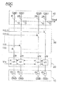
図1に示すように、本発明の利得制御増幅器AGCは、
N個の出力端子を有し、N個の電流源IOからなるバイアス段であって、各電流源の一端が負電源端子GNDに接続され、他端が前記N個の出力端子の一つを構成するバイアス段10と、
当該増幅器のアナログ入力端子を構成する電圧入力端子と、バイアス段のN個の出力端子に接続されたN個の電流入力端子と、N個の電流出力端子とを有し、N個の相互コンダクタンスモジュールV/Iからなる相互コンダクタンス段であって、各モジュールが当該段の電圧入力端子に接続された電圧入力端子と、当該段のN個の電流入力端子の1つを構成する電流入力端子と、当該段のN個の電流出力端子の一つを構成し、アナログ入力電圧Vinを表す可変成分を有する電流Itrを出力する電流出力端子とを有している相互コンダクタンス段20と、
N個の制御入力端子と、N個の電流入力端子と、N個の電流出力端子とを有するとともに、N個のスイッチを具えるスイッチング段であって、各スイッチがN個の制御入力端子の1つに受信された信号C(0),..C(N−1)により制御され、各スイッチの一端が当該段のN個の電流入力端子の一つを構成し、各スイッチの他端が当該段のN個の電流出力端子の一つを構成し、当該段のN個の電流入力端子が相互コンダクタンス段のN個の出力端子に接続され、当該段のN個の制御入力端子が当該増幅器の制御ワードC(0:N−1)受信用ディジタル入力端子を構成するスイッチング段30と、
N個の電流入力端子と1つの電圧出力端子を有し、N個の電流入力端子がスイッチング段のN個の電流出力端子に接続され、電圧出力端子が当該増幅器のアナログ出力端子を構成し、そのN個の電流入力端子に受信された電流を表す電圧Vout を出力する電流/ 電圧変換段40とを具える。この電流/電圧変換段40は本例ではR/2R回路網である。
【0019】
このような利得制御増幅器においては、電流ItrはIO/2+K・Vin・IO/2又は(1+K・Vin)IO/2と書き表すことができる。スイッチング段の性質及びR/2R回路網の特性のために、この増幅器の出力電圧Vout はItr・R・CODE/2N になり、従って(1+K・Vin)・R・IO・CODE/2N+1 と書き表せる。ここで、CODEは制御ワードの10進値である。この場合、出力電圧と入力電圧の可変成分の比として定義されるダイナミック利得Gd はGd =K・IO・R・CODE/2N+1 と書き表すことができ、制御ワードの値CODEにより有効に決まる。
【0020】
相互コンダクタンス段の出力は本例では非対称である。これらの出力を対称にする場合には、スイッチング段のスイッチを二重にするとともに、電流/電圧変換段を例えば2重R/2R回路網により構成すれば、この2重R/2R回路網が対称アナログ出力電圧を出力する。
【0021】
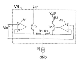
図2は本発明の変形例に従って利得制御増幅器AGC内に配置された相互コンダクタンスモジュールV/Iを図式的に示す。このモジュールは差動対として配置された2つのトランジスタT1,T2を具え、これらのトランジスタのエミッタは負帰還抵抗R1を経てバイアス段内の電流源IOに接続する。T1のコレクタは相互コンダクタンスモジュールV/Iの出力端子を構成し、T2のコレクタは抵抗R2を経て正電源端子VCに接続する。T1のベースはT1のエミッタに接続された反転入力端子を有する演算増幅器A1の出力端子に接続する。T2のベースはT2のエミッタに接続された反転入力端子を有する演算増幅器A2の出力端子に接続する。アナログ入力電圧Vinは2つの演算増幅器A1及びA2の2つの非反転入力端子間に供給する。この構成は相互コンダクタンスモジュールの一例であって、その出力電流Itrは電流源により供給される電流IOと無関係の可変成分を有する。確かに、IOの変化によるトランジスタのベース−エミッタ電圧の変調は演算増幅器の高利得分の一に減少する。この利得は100以上であるので、この変調は無視しうる。itr を相互コンダクタンスモジュールの出力電流の可変成分とし、ic2 をT2のコレクタを流れる電流の可変成分とすると、その差itr-ic2 はVin/(2・R2)になる。itr=-ic2であるので、itr=Vin/(4・R2)である。従って、この相互コンダクタンスモジュールの出力電流は:Itr=IO/2+Vin/(4・R2)、又はItr=IO/2+K’・Vinと書き表すことができる。従って、図2に示す相互コンダクタンスモジュールV/Iを含む図1に示す利得制御増幅器の出力電圧Vout はVout =Itr・R・CODE/2N 、即ち
Vout =IO・R・CODE/2N+1 +K’・Vin・CODE/2N
になる。従って、このような相互コンダクタンスモジュールは増幅器のアナログ出力電圧のDC成分を、この増幅器のダイナミック利得を変更することなくセットすることができる。これはビデオ信号の処理に極めて有用であり、その信号をそのDCレベルを変更する必要なく可変式に増幅することができる(このDCレベルは基準レベルを構成し、増幅信号の次の処理のために使用される)。
【0022】
図3は増幅器のアナログ出力電圧のDCレベルを設定する装置を図式的に示す。この装置は、1つの入力端子と2つの出力端子を有し、一方の入力端子が基準電圧Vref を受信し、他方の入力端子が増幅器の出力電圧Vout を受信する比較器AOを具える。図3はバイアス段の電流源の一つも示し、本例ではこの電流源はエミッタが抵抗R0を経て負電源端子GNDに接続されたトランジスタTOからなる。トランジスタTOのベースがこの電流源により供給される電流値IOを制御する入力端子を構成する。比較器AOの出力端子をバイアス段の各電流源の制御入力端子に接続する。制御ワードの値CODEがVout の高すぎる増大を導き、そのDCレベルの増大を導くとき、比較器AOの出力電圧が減少し、トランジスタTOの導通の低下を導く。このときIOが減少し、上記の式:
Vout =IO・R・CODE/2N+1 +K’・Vin・CODE/2N
で表されるアナログ出力電圧Vout のDC成分のCODEによる増大を補償する。ダイナミック利得は不変のままである。
【0023】
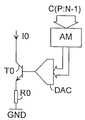
図4は増幅器のアナログ出力電圧のDCレベルを設定する他の装置を図式的に示す。この装置は、制御ワードの少なくとも一部分C(P:N−1)によりアドレスされ、制御ワードの前記部分の組合せに対応する予め計算されたディジタル値を出力端子に供給する連想メモリAMを具える。この設定装置は連想メモリAMの出力端子に接続された入力端子を有するD/A変換器DACも具える。図4はバイアス段の電流源の一つも示し、本例ではこの電流源はエミッタが抵抗R0を経て負電源端子GNDに接続されたトランジスタTOからなる。トランジスタTOのベースがこの電流源により供給される電流値IOを制御する入力端子を構成する。D/A変換器DACの出力端子をバイアス段の各電流源の制御入力端子に接続する。連想メモリにより電流IOの値を急速に調整することができる。実際上、連想メモリAMをアドレスする制御ワードの部分C(P:N−1)の各別の組合せが、このメモリ内に記憶されている、アナログ出力電圧のDC成分の値を与える式に基づいて予め計算された値にそれぞれ対応する。この構成はバイアス電流IOに対する値をCODEの値に反比例して発生し、DCレベルの値を一定にする。従って、CODEのこの値と関連するディジタルワードは、アナログ形態に変換された後にトランジスタTOのベースをこのトランジスタが予め計算された電流IOを供給するように制御するワードである。連想メモリAMをアドレスする制御ワードの部分C(P:N−1)のビット数(N−P−1)を多くすればするほど、メモリは多数の予め計算された値を含み、IOの設定が一層精密になる。従って、アナログ出力電圧のDCレベルの設定が精密になる。
【0024】
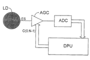
図5は本発明の利得制御増幅器を具えるカメラを部分的に示す図である。このカメラは、
光を検出し、アナログ電子信号ESに変換する装置LDと、
前記アナログ電子信号ESを受信するアナログ信号入力端子と、制御ワードという利得制御用のディジタルワードC(0:N−1)を受信するディジタル入力端子と、アナログ信号出力端子とを有する上述の増幅器AGCと、
増幅器AGCの出力端子に接続されたアナログ入力端子とディジタル出力端子とを有するA/D変換器ADCと、
A/D変換器ADCの出力端子に接続された入力端子を有し、ディジタル制御ワードC(0:N−1)を増幅器AGCに送出するディジタル処理ユニットDPUとを具える。
【図面の簡単な説明】
【図1】本発明の利得制御増幅器を部分的に示す構成図である。
【図2】本発明の利得制御増幅器の変形例内に配置された相互コンダクタンスモジュールを示す構成図である。
【図3】本発明の利得制御増幅器の有利な実施例内のDCレベル設定装置を示す構成図である。
【図4】本発明の利得制御増幅器の他の有利な実施例内のDCレベル設定装置を示す構成図である。
【図5】本発明の利得制御増幅器を使用するカメラを部分的に示す構成図である。
【符号の説明】
10 バイアス段
20 相互コンダクタンス段
30 スイッチング段
40 電流/電圧変換段[0001]
BACKGROUND OF THE INVENTION
The present invention relates to a gain control amplifier having an analog input terminal that receives an analog input voltage, a digital input terminal that receives an N-bit word for gain control called a control word, and an analog output terminal that outputs an analog output voltage. Is.
[0002]
[Prior art]
Most amplifiers that are gain controlled by a digital control word include a D / A converter that converts the control word to an analog signal. The analog signal is then used to control the continuity of the current source that biases the amplification stage that actually amplifies the analog input voltage, or this analog signal is used as a multiplier for the analog input signal of the multiplier circuit.
[0003]
Therefore, these gain control amplifiers have two major drawbacks: the circuit size increases due to the D / A converters they provide, and the errors that occur in the conversion of the control word are inherent in the amplifier. Has the disadvantage of being doubled.
[0004]
[Problems to be solved by the invention]
The object of the present invention is to eliminate these drawbacks by providing an amplifier in which the control word directly affects the amplification result of the analog input voltage.
[0005]
[Means for Solving the Problems]
For this purpose, the gain control amplifier of the present invention comprises:
A means for generating a current having a variable component representing an analog input voltage is provided at each of the N output terminals, the voltage input terminal constituting the analog input terminal of the amplifier and N current output terminals. A transconductance stage;
Having N control input terminals and comprising N switches, each switch being controlled by a signal received at one of the N control input terminals, of the N current output terminals of the transconductance stage; A switching stage that controls one activation or deactivation and the N control input terminals constitute a digital input terminal that receives the control word of the amplifier;
N current input terminals and one voltage output terminal, the N current input terminals are connected to the N current output terminals of the mutual conductance, and the voltage output terminal is an analog output terminal of the amplifier. A current / voltage conversion stage configured to output a voltage representing the current received at the N current input terminals;
It is characterized by comprising.
[0006]
In such an amplifier, the actual amplification is performed directly in the transconductance stage regardless of the value of the control word. The switching stage directly selects the output terminal of the transconductance stage to be activated in response to the control word. The analog output voltage is the result of a linear combination of the outputs of the transconductance stages, which is realized by a current / voltage conversion stage. The result of this coupling varies as a function of the number and nature of the activated outputs of the transconductance stage and thus as a function of the digital value of the control word.
[0007]
In one embodiment of the present invention, in the gain control amplifier described in the introduction, the amplifier comprises:
A bias stage having N output terminals and including N current sources, one end of each current source being connected to a negative power supply terminal and the other end being one of the N output terminals. A bias stage comprising:
A voltage input terminal that constitutes an analog input terminal of the amplifier, N current input terminals connected to the N output terminals of the bias stage, and N current output terminals; A transconductance stage composed of transconductance modules, each module being connected to a voltage input terminal of the stage and a current input terminal constituting one of the N current input terminals of the stage A transconductance stage having one of N current output terminals of the stage and a current output terminal for outputting a current having a variable component representing an analog input voltage;
A switching stage having N control input terminals, N current input terminals, and N current output terminals, and including N switches, each switch including the N control input terminals. One end of each switch constitutes one of the N current input terminals of the stage, and the other end of each switch is one of the N current output terminals of the stage. A digital input terminal for connecting the N current input terminals of the stage to the N output terminals of the transconductance stage, and the N control input terminals of the stage receiving the control word of the amplifier A switching stage comprising:
N current input terminals and one voltage output terminal, the N current input terminals are connected to the N current output terminals of the switching stage, and the voltage output terminal is an analog output terminal of the amplifier. And a current / voltage conversion stage that outputs a voltage representing the current received at the N current input terminals,
It is characterized by comprising.
[0008]
In another embodiment of the present invention, in the gain control amplifier described above, the current / voltage conversion stage comprises an R / 2R network in which two consecutive current input terminals are nominally equal to R. The current output terminal connected to the output terminal of the transconductance stage controlled by the most significant bit of the control word is connected to the analog output terminal of the amplifier via a resistor having a nominal value equal to R. A current input terminal connected to the output terminal of the transconductance controlled by the least significant bit of the control word is connected to the negative power supply terminal via a resistor having a nominal value equal to R, each of the other current input terminals Is connected to the negative power supply terminal via a resistor having a nominal value equal to 2R.
[0009]
According to the current / voltage conversion stage realized by the R / 2R network, the current received at each current input terminal can be weighted and combined as a function of the position occupied by each current input terminal. Thus, such a configuration is well suited for applications where the value of the output depends on a digital control word having various weight bits.
[0010]
This is particularly useful in the modified example of the present invention. In this modified example, in the above-described gain control amplifier, all the current sources of the bias stage have the same configuration, and a control input terminal is provided in each current source. The current value supplied by the current source is controlled as a function of the value of the control word.
[0011]
In such a current amplifier, the weighting required to control the amplifier gain as a function of the value of the control word is achieved only by the R / 2R network.
[0012]
In another modification of the present invention, in the above-described gain control amplifier, each of the transconductance modules is supplied with a current having a variable component unrelated to the value of the current supplied by the current source connected to the module. It is characterized in that means for generating is provided.
[0013]
According to this variant of the invention, the DC level of the analog output voltage can be changed by changing the value of the current supplied by the current source of the bias stage without having to change the value of the gain applied to the analog input current. Can be adjusted.
[0014]
In an advantageous embodiment of the invention in which the DC level of the analog output voltage can be adjusted, in the above-described gain control amplifier, the amplifier comprises a comparator having one output terminal and two input terminals, One input terminal receives the reference voltage, the other input terminal receives the output voltage of the amplifier, and the output terminal of the comparator is connected to the control input terminal of each current source of the bias stage. Features.
[0015]
In another advantageous embodiment of the invention in which the DC level of the analog output voltage can be set, in the above-described gain control amplifier, the amplifier is addressed by at least a part of the control word and corresponds to a combination of said part of the control word Providing an associative memory for supplying a pre-calculated digital value to its output terminal, the amplifier further connected to a digital input terminal connected to the output terminal of the associative memory and a control input terminal of each current source of the bias stage And a D / A converter having an analog output terminal.
[0016]
The present invention also relates to a camera.
A device that detects light and converts it to an analog electronic signal;
An amplifier having an analog signal input terminal for receiving the analog electronic signal, a digital input terminal for receiving a gain control digital word called a control word, and an analog signal output terminal;
An A / D converter having an analog input terminal and a digital output terminal connected to the output terminal of the amplifier;
A digital processing device having an input terminal connected to the output terminal of the A / D converter and supplying a control word to the amplifier;
In a camera with
The amplifier is an amplifier configured as described above.
[0017]
DETAILED DESCRIPTION OF THE INVENTION
These and other features of the present invention will become apparent from the description of the examples set forth below.
[0018]
As shown in FIG. 1, the gain control amplifier AGC of the present invention has
A bias stage having N output terminals and including N current sources IO, one end of each current source being connected to the negative power supply terminal GND and the other end being one of the N output terminals. Comprising a
The amplifier has a voltage input terminal constituting an analog input terminal of the amplifier, N current input terminals connected to the N output terminals of the bias stage, and N current output terminals, and N transconductances. A transconductance stage comprising modules V / I, each module being connected to a voltage input terminal of the stage, and a current input terminal constituting one of N current input terminals of the stage; A
A switching stage having N control input terminals, N current input terminals, and N current output terminals and including N switches, each switch having N control input terminals. The signals C (0),. . C (N-1), one end of each switch constitutes one of the N current input terminals of the stage, and the other end of each switch constitutes one of the N current output terminals of the stage. The N current input terminals of the stage are connected to the N output terminals of the transconductance stage, and the N control input terminals of the stage receive the control word C (0: N-1) of the amplifier. A switching
N current input terminals and one voltage output terminal, the N current input terminals are connected to the N current output terminals of the switching stage, and the voltage output terminal constitutes an analog output terminal of the amplifier, A current /
[0019]
In such a gain control amplifier, the current Itr can be written as IO / 2 + K · Vin · IO / 2 or (1 + K · Vin) IO / 2. Due to the nature of the switching stage and the characteristics of the R / 2R network, the output voltage Vout of this amplifier will be Itr.R.CODE / 2 N , therefore (1 + K.Vin) .R.IO.CODE / 2 N +. Can be written as 1 . Here, CODE is the decimal value of the control word. In this case, the dynamic gain Gd defined as the ratio of the variable component of the output voltage and the input voltage can be expressed as Gd = K.IO.R.CODE / 2 N + 1, and is effectively determined by the value CODE of the control word. .
[0020]
The output of the transconductance stage is asymmetric in this example. In order to make these outputs symmetrical, if the switch of the switching stage is doubled and the current / voltage conversion stage is configured by, for example, a double R / 2R network, this double R / 2R network is Outputs symmetric analog output voltage.
[0021]
FIG. 2 schematically shows a transconductance module V / I arranged in a gain control amplifier AGC according to a variant of the invention. This module comprises two transistors T1, T2 arranged as a differential pair, the emitters of which are connected via a negative feedback resistor R1 to a current source IO in the bias stage. The collector of T1 constitutes the output terminal of the mutual conductance module V / I, and the collector of T2 is connected to the positive power supply terminal VC via the resistor R2. The base of T1 is connected to the output terminal of an operational amplifier A1 having an inverting input terminal connected to the emitter of T1. The base of T2 is connected to the output terminal of an operational amplifier A2 having an inverting input terminal connected to the emitter of T2. The analog input voltage Vin is supplied between the two non-inverting input terminals of the two operational amplifiers A1 and A2. This configuration is an example of a transconductance module, and its output current Itr has a variable component unrelated to the current IO supplied by the current source. Certainly, the modulation of the base-emitter voltage of the transistor due to the change in IO is reduced by a factor of the high gain of the operational amplifier. Since this gain is greater than 100, this modulation is negligible. If itr is a variable component of the output current of the transconductance module and ic2 is a variable component of the current flowing through the collector of T2, the difference itr-ic2 is Vin / (2 · R2). Since itr = −ic2, itr = Vin / (4 · R2). Therefore, the output current of this transconductance module can be written as: Itr = IO / 2 + Vin / (4 · R2), or Itr = IO / 2 + K ′ · Vin. Accordingly, the output voltage Vout of the gain control amplifier shown in FIG. 1 including the transconductance module V / I shown in FIG. 2 is Vout = Itr · R · CODE / 2 N , that is, Vout = IO · R · CODE / 2 N + 1. + K '· Vin · CODE / 2 N
become. Accordingly, such a transconductance module can set the DC component of the amplifier's analog output voltage without changing the dynamic gain of the amplifier. This is extremely useful for processing video signals, and the signal can be variably amplified without the need to change its DC level (this DC level constitutes the reference level for subsequent processing of the amplified signal). Used).
[0022]
FIG. 3 schematically shows an apparatus for setting the DC level of the analog output voltage of the amplifier. The device comprises a comparator AO having one input terminal and two output terminals, one input terminal receiving the reference voltage Vref and the other input terminal receiving the amplifier output voltage Vout. FIG. 3 also shows one of the current sources in the bias stage, and in this example, this current source comprises a transistor TO whose emitter is connected to the negative power supply terminal GND via a resistor R0. The base of the transistor TO constitutes an input terminal for controlling the current value IO supplied by this current source. The output terminal of the comparator AO is connected to the control input terminal of each current source in the bias stage. When the value CODE of the control word leads to an increase in Vout that is too high, leading to an increase in its DC level, the output voltage of the comparator AO decreases, leading to a decrease in the conduction of the transistor TO. At this time, IO decreases, and the above formula:
Vout = IO.R.CODE / 2 N + 1 + K'.Vin.CODE / 2 N
Is compensated for the increase in the DC component of the analog output voltage Vout expressed by CODE. The dynamic gain remains unchanged.
[0023]
FIG. 4 schematically shows another device for setting the DC level of the analog output voltage of the amplifier. The apparatus comprises an associative memory AM addressed by at least a part C (P: N-1) of the control word and supplying a pre-calculated digital value corresponding to the combination of said part of the control word to the output terminal. The setting device also includes a D / A converter DAC having an input terminal connected to the output terminal of the associative memory AM. FIG. 4 also shows one of the current sources in the bias stage, and in this example, this current source comprises a transistor TO whose emitter is connected to the negative power supply terminal GND via a resistor R0. The base of the transistor TO constitutes an input terminal for controlling the current value IO supplied by this current source. The output terminal of the D / A converter DAC is connected to the control input terminal of each current source in the bias stage. The value of the current IO can be rapidly adjusted by the associative memory. In practice, each different combination of the control word portions C (P: N-1) addressing the associative memory AM is based on an equation which gives the value of the DC component of the analog output voltage stored in this memory. Correspond to the values calculated in advance. This configuration generates a value for the bias current IO in inverse proportion to the value of CODE, and makes the value of the DC level constant. Thus, the digital word associated with this value of CODE is the word that controls the base of transistor TO so that it supplies a pre-calculated current IO after being converted to analog form. The larger the number of bits (N-P-1) of the part C (P: N-1) of the control word that addresses the associative memory AM, the more the memory contains more pre-calculated values and the IO setting Becomes more precise. Therefore, the setting of the DC level of the analog output voltage becomes precise.
[0024]
FIG. 5 is a diagram partially showing a camera including the gain control amplifier of the present invention. This camera
A device LD for detecting light and converting it into an analog electronic signal ES;
The above-described amplifier AGC having an analog signal input terminal for receiving the analog electronic signal ES, a digital input terminal for receiving a gain control digital word C (0: N-1), which is a control word, and an analog signal output terminal. When,
An A / D converter ADC having an analog input terminal and a digital output terminal connected to the output terminal of the amplifier AGC;
A digital processing unit DPU having an input terminal connected to the output terminal of the A / D converter ADC and sending a digital control word C (0: N-1) to the amplifier AGC;
[Brief description of the drawings]
FIG. 1 is a block diagram partially showing a gain control amplifier according to the present invention.
FIG. 2 is a block diagram showing a transconductance module arranged in a modification of the gain control amplifier of the present invention.
FIG. 3 is a block diagram showing a DC level setting device in an advantageous embodiment of the gain control amplifier of the present invention.
FIG. 4 is a block diagram showing a DC level setting device in another advantageous embodiment of the gain control amplifier of the present invention.
FIG. 5 is a block diagram partially showing a camera using the gain control amplifier of the present invention.
[Explanation of symbols]
10 Bias stage
20 transconductance stage
30 switching stages
40 Current / voltage conversion stage
Claims (8)
当該増幅器のアナログ入力端子を構成する電圧入力端子とN個の電流出力端子を有し、且つ該N個の出力端子の各々にアナログ入力電圧を表す可変成分を有する電流を発生する手段が設けられ、アナログ入力電圧の増幅を制御ワードの値と無関係に直接行うように構成された相互コンダクタンス段と、
N個の制御入力端子を有するとともにN個のスイッチを具え、各スイッチが該N個の制御入力端子の1つに受信される信号により制御され、前記相互コンダクタンス段のN個の電流出力端子の1つの活性化又は不活性化を制御し、該N個の制御入力端子が当該増幅器の制御ワードを受信するディジタル入力端子を構成するスイッチング段と、
N個の電流入力端子と1つの電圧出力端子を有し、該N個の電流入力端子が前記相互コンダクタンスのN個の電流出力端子に接続され、該電圧出力端子が当該増幅器のアナログ出力端子を構成し、そのN個の電流入力端子に受信された電流を表す電圧を供給する電流/電圧変換段と、
を具えたことを特徴とする利得制御増幅器。A gain control amplifier having an analog input terminal for receiving an analog input voltage, a digital input terminal for receiving an N-bit word for gain control called a control word, and an analog output terminal for outputting an analog output voltage. ,
Means is provided for generating a current having a voltage input terminal constituting the analog input terminal of the amplifier and N current output terminals, and each of the N output terminals having a variable component representing the analog input voltage. A transconductance stage configured to directly amplify the analog input voltage independently of the value of the control word ;
Having N control input terminals and comprising N switches, each switch being controlled by a signal received at one of the N control input terminals, of the N current output terminals of the transconductance stage; A switching stage that controls one activation or deactivation and the N control input terminals constitute a digital input terminal that receives the control word of the amplifier;
N current input terminals and one voltage output terminal, the N current input terminals are connected to the N current output terminals of the mutual conductance, and the voltage output terminal is an analog output terminal of the amplifier. A current / voltage conversion stage configured to supply a voltage representing the received current to the N current input terminals;
A gain control amplifier characterized by comprising:
N個の出力端子を有し、且つN個の電流源で構成されたバイアス段であって、各電流源の一端が負電源端子に接続され、他端が該N個の出力端子の一つを構成するバイアス段と、
当該増幅器のアナログ入力端子を構成する電圧入力端子と、前記バイアス段のN個の出力端子に接続されたN個の電流入力端子と、N個の電流出力端子とを有し、且つN個の相互コンダクタンスモジュールで構成された相互コンダクタンス段であって、各モジュールが当該段の電圧入力端子に接続された電圧入力端子と、当該段の電流入力端子を構成する電流入力端子と、当該段のN個の電流出力端子の一つを構成し、アナログ入力電圧を表す可変成分を有する電流を出力する電流出力端子とを有している相互コンダクタンス段と、
N個の制御入力端子と、N個の電流入力端子と、N個の電流出力端子とを有するとともに、N個のスイッチを具えるスイッチング段であって、各スイッチが該N個の制御入力端子の1つに受信された信号により制御され、各スイッチの一端が当該段のN個の電流入力端子の一つを構成し、各スイッチの他端が当該段のN個の電流出力端子の一つを構成し、当該段のN個の電流入力端子が前記相互コンダクタンス段のN個の出力端子に接続され、当該段のN個の制御入力端子が当該増幅器の制御ワードを受信するディジタル入力端子を構成するスイッチング段と、
N個の電流入力端子と一つの電圧出力端子を有し、該N個の電流入力端子が前記スイッチング段のN個の電流出力端子に接続され、該電圧出力端子が当該増幅器のアナログ出力端子を構成し、該N個の電流入力端子に受信された電流を表す電圧を出力する電流/電圧変換段と、
を具えたことを特徴とする利得制御増幅器。A gain control amplifier having an analog input terminal for receiving an analog input voltage, a digital input terminal for receiving an N-bit word for gain control called a control word, and an analog output terminal for outputting an analog output voltage. ,
A bias stage having N output terminals and including N current sources, one end of each current source being connected to a negative power supply terminal and the other end being one of the N output terminals. A bias stage comprising:
A voltage input terminal that constitutes an analog input terminal of the amplifier, N current input terminals connected to the N output terminals of the bias stage, and N current output terminals; A transconductance stage composed of transconductance modules, each module being connected to a voltage input terminal of the stage, a current input terminal constituting the current input terminal of the stage, and an N of the stage A transconductance stage comprising one current output terminal and a current output terminal for outputting a current having a variable component representing an analog input voltage;
A switching stage having N control input terminals, N current input terminals, and N current output terminals, and including N switches, each switch including the N control input terminals. One end of each switch constitutes one of the N current input terminals of the stage, and the other end of each switch is one of the N current output terminals of the stage. A digital input terminal for connecting the N current input terminals of the stage to the N output terminals of the transconductance stage, and the N control input terminals of the stage receiving the control word of the amplifier A switching stage comprising:
N current input terminals and one voltage output terminal, the N current input terminals are connected to the N current output terminals of the switching stage, and the voltage output terminal is an analog output terminal of the amplifier. A current / voltage conversion stage configured to output a voltage representing the current received at the N current input terminals;
A gain control amplifier characterized by comprising:
前記アナログ電子信号を受信するアナログ信号入力端子と、制御ワードという利得制御用のディジタルワードを受信するディジタル入力端子と、アナログ信号出力端子とを有する増幅器と、
前記増幅器の出力端子に接続されたアナログ入力端子とディジタル出力端子とを有するA/D変換器と、
前記A/D変換器の出力端子に接続された入力端子を有し、制御ワードを前記増幅器に供給するディジタル処理装置とを具えたカメラにおいて、
前記増幅器が請求項1〜7の何れかに記載された増幅器であることを特徴とするカメラ。A device that detects light and converts it to an analog electronic signal;
An amplifier having an analog signal input terminal for receiving the analog electronic signal, a digital input terminal for receiving a gain control digital word called a control word, and an analog signal output terminal;
An A / D converter having an analog input terminal and a digital output terminal connected to the output terminal of the amplifier;
In a camera comprising an input terminal connected to the output terminal of the A / D converter, and a digital processing device for supplying a control word to the amplifier,
A camera, wherein the amplifier is an amplifier according to any one of claims 1 to 7.
Applications Claiming Priority (2)
| Application Number | Priority Date | Filing Date | Title |
|---|---|---|---|
| FR9607446A FR2749992A1 (en) | 1996-06-14 | 1996-06-14 | DIGITALLY CONTROLLED GAIN AMPLIFIER AND CAMERA IMPLEMENTING SUCH AMPLIFIER |
| FR9607446 | 1996-06-14 |
Publications (2)
| Publication Number | Publication Date |
|---|---|
| JPH1070424A JPH1070424A (en) | 1998-03-10 |
| JP4046801B2 true JP4046801B2 (en) | 2008-02-13 |
Family
ID=9493077
Family Applications (1)
| Application Number | Title | Priority Date | Filing Date |
|---|---|---|---|
| JP15333597A Expired - Lifetime JP4046801B2 (en) | 1996-06-14 | 1997-06-11 | Gain control amplifier and camera using the amplifier |
Country Status (6)
| Country | Link |
|---|---|
| US (1) | US5917380A (en) |
| EP (1) | EP0813295B1 (en) |
| JP (1) | JP4046801B2 (en) |
| DE (1) | DE69716674T2 (en) |
| FR (1) | FR2749992A1 (en) |
| MY (1) | MY119436A (en) |
Families Citing this family (7)
| Publication number | Priority date | Publication date | Assignee | Title |
|---|---|---|---|---|
| JPH11340760A (en) * | 1998-05-28 | 1999-12-10 | Fuji Film Microdevices Co Ltd | Variable gain amplifier circuit |
| FR2818466B1 (en) * | 2000-12-15 | 2003-04-04 | St Microelectronics Sa | VARIABLE GAIN DIFFERENTIAL INPUT AND OUTPUT AMPLIFIER |
| EP1751850B1 (en) | 2004-05-17 | 2008-12-10 | Nxp B.V. | Plop noise avoidance for an amplifier |
| US7813199B2 (en) * | 2008-04-22 | 2010-10-12 | Micron Technology, Inc. | Current mode data sensing and propagation using voltage amplifier |
| JP5252212B2 (en) | 2009-03-12 | 2013-07-31 | ルネサスエレクトロニクス株式会社 | Semiconductor device for signal amplification |
| TWI424684B (en) * | 2010-07-06 | 2014-01-21 | Novatek Microelectronics Corp | Amplifier and gain modulation method with wide range |
| GB2504060B (en) * | 2012-05-21 | 2019-01-09 | Lime Microsystems Ltd | Attenuation circuit |
Family Cites Families (5)
| Publication number | Priority date | Publication date | Assignee | Title |
|---|---|---|---|---|
| US4335356A (en) * | 1980-01-21 | 1982-06-15 | Tektronix, Inc. | Programmable two-quadrant transconductance amplifier |
| US4543561A (en) * | 1980-02-12 | 1985-09-24 | Analog Devices, Incorporated | Single-supply IC digital-to-analog converter for use with microprocessors |
| US4462003A (en) * | 1983-01-10 | 1984-07-24 | Sony/Tektronix | Variable gain amplifier |
| US4791446A (en) * | 1986-02-14 | 1988-12-13 | Minolta Camera Kabushiki Kaisha | Light measuring device |
| FR2714237B1 (en) * | 1993-12-17 | 1996-01-26 | Thomson Csf Semiconducteurs | Variable gain amplifier. |
-
1996
- 1996-06-14 FR FR9607446A patent/FR2749992A1/en not_active Withdrawn
-
1997
- 1997-06-05 DE DE69716674T patent/DE69716674T2/en not_active Expired - Lifetime
- 1997-06-05 EP EP97201706A patent/EP0813295B1/en not_active Expired - Lifetime
- 1997-06-11 JP JP15333597A patent/JP4046801B2/en not_active Expired - Lifetime
- 1997-06-12 MY MYPI97002609A patent/MY119436A/en unknown
- 1997-06-12 US US08/873,374 patent/US5917380A/en not_active Expired - Lifetime
Also Published As
| Publication number | Publication date |
|---|---|
| EP0813295A1 (en) | 1997-12-17 |
| DE69716674T2 (en) | 2003-06-12 |
| EP0813295B1 (en) | 2002-10-30 |
| JPH1070424A (en) | 1998-03-10 |
| DE69716674D1 (en) | 2002-12-05 |
| FR2749992A1 (en) | 1997-12-19 |
| US5917380A (en) | 1999-06-29 |
| MY119436A (en) | 2005-05-31 |
Similar Documents
| Publication | Publication Date | Title |
|---|---|---|
| US5283579A (en) | Digital to analog converter having high multiplying bandwidth | |
| JP3967065B2 (en) | Amplifier circuit | |
| KR100457479B1 (en) | Gain-Controlled Amplifiers and Cameras | |
| JP4046801B2 (en) | Gain control amplifier and camera using the amplifier | |
| JPS59171B2 (en) | electronic switching circuit | |
| JP3340250B2 (en) | Buffer circuit | |
| JP2006311361A (en) | Attenuator, and variable gain amplifier and electronic equipment using the same | |
| JP3360032B2 (en) | Partially temperature compensated low noise voltage reference | |
| JP2000505605A (en) | Digital-to-analog converter and dynamic current mirror structure to simplify on-chip waveform shaping | |
| EP0661804B1 (en) | Volume controller | |
| JP3078858B2 (en) | VCA circuit | |
| JPH10276052A (en) | Variable gain amplifier circuit | |
| JPH0436609B2 (en) | ||
| JPH09186595A (en) | Voltage amplifier and a/d converter using it | |
| JPH031709A (en) | Variable resistance circuit and variable gain amplifier | |
| JPH08274642A (en) | DA converter and DA converter device | |
| CN112994624A (en) | Calibration of audio power amplifier DC offset | |
| JP2824837B2 (en) | Analog-to-digital converter | |
| WO2003028210A1 (en) | Variable gain amplifier of low power consumption | |
| JPH08307273A (en) | D/a converter circuit | |
| JP3118870B2 (en) | Error amplification circuit | |
| JPH0636160B2 (en) | Analog signal comparison circuit | |
| EP0557052A2 (en) | Analog to digital converter | |
| JP2001094368A (en) | Arithmetic amplifier circuit | |
| KR960013042B1 (en) | Amplifier Gain Control Circuit Through Impedance Control |
Legal Events
| Date | Code | Title | Description |
|---|---|---|---|
| A621 | Written request for application examination |
Free format text: JAPANESE INTERMEDIATE CODE: A621 Effective date: 20040609 |
|
| A131 | Notification of reasons for refusal |
Free format text: JAPANESE INTERMEDIATE CODE: A131 Effective date: 20060509 |
|
| A601 | Written request for extension of time |
Free format text: JAPANESE INTERMEDIATE CODE: A601 Effective date: 20060809 |
|
| A602 | Written permission of extension of time |
Free format text: JAPANESE INTERMEDIATE CODE: A602 Effective date: 20060821 |
|
| A131 | Notification of reasons for refusal |
Free format text: JAPANESE INTERMEDIATE CODE: A131 Effective date: 20070220 |
|
| A601 | Written request for extension of time |
Free format text: JAPANESE INTERMEDIATE CODE: A601 Effective date: 20070521 |
|
| A602 | Written permission of extension of time |
Free format text: JAPANESE INTERMEDIATE CODE: A602 Effective date: 20070524 |
|
| A521 | Request for written amendment filed |
Free format text: JAPANESE INTERMEDIATE CODE: A523 Effective date: 20070710 |
|
| RD03 | Notification of appointment of power of attorney |
Free format text: JAPANESE INTERMEDIATE CODE: A7423 Effective date: 20070710 |
|
| TRDD | Decision of grant or rejection written | ||
| A01 | Written decision to grant a patent or to grant a registration (utility model) |
Free format text: JAPANESE INTERMEDIATE CODE: A01 Effective date: 20071113 |
|
| A61 | First payment of annual fees (during grant procedure) |
Free format text: JAPANESE INTERMEDIATE CODE: A61 Effective date: 20071121 |
|
| FPAY | Renewal fee payment (event date is renewal date of database) |
Free format text: PAYMENT UNTIL: 20101130 Year of fee payment: 3 |
|
| R150 | Certificate of patent or registration of utility model |
Free format text: JAPANESE INTERMEDIATE CODE: R150 |
|
| FPAY | Renewal fee payment (event date is renewal date of database) |
Free format text: PAYMENT UNTIL: 20101130 Year of fee payment: 3 |
|
| S111 | Request for change of ownership or part of ownership |
Free format text: JAPANESE INTERMEDIATE CODE: R313113 |
|
| FPAY | Renewal fee payment (event date is renewal date of database) |
Free format text: PAYMENT UNTIL: 20101130 Year of fee payment: 3 |
|
| R350 | Written notification of registration of transfer |
Free format text: JAPANESE INTERMEDIATE CODE: R350 |
|
| FPAY | Renewal fee payment (event date is renewal date of database) |
Free format text: PAYMENT UNTIL: 20101130 Year of fee payment: 3 |
|
| FPAY | Renewal fee payment (event date is renewal date of database) |
Free format text: PAYMENT UNTIL: 20111130 Year of fee payment: 4 |
|
| FPAY | Renewal fee payment (event date is renewal date of database) |
Free format text: PAYMENT UNTIL: 20111130 Year of fee payment: 4 |
|
| FPAY | Renewal fee payment (event date is renewal date of database) |
Free format text: PAYMENT UNTIL: 20121130 Year of fee payment: 5 |
|
| FPAY | Renewal fee payment (event date is renewal date of database) |
Free format text: PAYMENT UNTIL: 20121130 Year of fee payment: 5 |
|
| FPAY | Renewal fee payment (event date is renewal date of database) |
Free format text: PAYMENT UNTIL: 20131130 Year of fee payment: 6 |
|
| R250 | Receipt of annual fees |
Free format text: JAPANESE INTERMEDIATE CODE: R250 |
|
| R250 | Receipt of annual fees |
Free format text: JAPANESE INTERMEDIATE CODE: R250 |
|
| R250 | Receipt of annual fees |
Free format text: JAPANESE INTERMEDIATE CODE: R250 |
|
| EXPY | Cancellation because of completion of term |