JP4045509B2 - Color ink droplet ejection order determination method and image forming method and apparatus - Google Patents
Color ink droplet ejection order determination method and image forming method and apparatus Download PDFInfo
- Publication number
- JP4045509B2 JP4045509B2 JP2005042629A JP2005042629A JP4045509B2 JP 4045509 B2 JP4045509 B2 JP 4045509B2 JP 2005042629 A JP2005042629 A JP 2005042629A JP 2005042629 A JP2005042629 A JP 2005042629A JP 4045509 B2 JP4045509 B2 JP 4045509B2
- Authority
- JP
- Japan
- Prior art keywords
- color
- droplet ejection
- ink
- order
- reflection density
- Prior art date
- Legal status (The legal status is an assumption and is not a legal conclusion. Google has not performed a legal analysis and makes no representation as to the accuracy of the status listed.)
- Expired - Fee Related
Links
- 238000000034 method Methods 0.000 title claims description 106
- 239000000976 ink Substances 0.000 claims description 327
- 239000003086 colorant Substances 0.000 claims description 65
- 230000000295 complement effect Effects 0.000 claims description 49
- 230000008859 change Effects 0.000 claims description 14
- 230000008021 deposition Effects 0.000 claims 1
- 238000007639 printing Methods 0.000 description 32
- 238000001514 detection method Methods 0.000 description 24
- 238000004891 communication Methods 0.000 description 19
- 238000003860 storage Methods 0.000 description 14
- 238000010586 diagram Methods 0.000 description 10
- 238000010438 heat treatment Methods 0.000 description 10
- 230000003595 spectral effect Effects 0.000 description 9
- 230000007423 decrease Effects 0.000 description 8
- 230000006870 function Effects 0.000 description 8
- 238000012545 processing Methods 0.000 description 8
- 239000000463 material Substances 0.000 description 7
- 230000003287 optical effect Effects 0.000 description 7
- 230000008569 process Effects 0.000 description 6
- 230000032258 transport Effects 0.000 description 6
- 238000004140 cleaning Methods 0.000 description 5
- 238000007599 discharging Methods 0.000 description 5
- 238000001035 drying Methods 0.000 description 5
- 238000012360 testing method Methods 0.000 description 5
- 238000011144 upstream manufacturing Methods 0.000 description 5
- 238000004364 calculation method Methods 0.000 description 4
- 238000001739 density measurement Methods 0.000 description 4
- 230000007246 mechanism Effects 0.000 description 4
- 239000000049 pigment Substances 0.000 description 4
- 238000010521 absorption reaction Methods 0.000 description 3
- 238000007664 blowing Methods 0.000 description 3
- 238000005259 measurement Methods 0.000 description 3
- 238000001179 sorption measurement Methods 0.000 description 3
- 238000006243 chemical reaction Methods 0.000 description 2
- 238000004040 coloring Methods 0.000 description 2
- 238000012937 correction Methods 0.000 description 2
- 238000000151 deposition Methods 0.000 description 2
- 238000013461 design Methods 0.000 description 2
- 230000000694 effects Effects 0.000 description 2
- 238000002474 experimental method Methods 0.000 description 2
- 239000007788 liquid Substances 0.000 description 2
- 239000011159 matrix material Substances 0.000 description 2
- 238000012986 modification Methods 0.000 description 2
- 230000004048 modification Effects 0.000 description 2
- 238000003672 processing method Methods 0.000 description 2
- 238000012546 transfer Methods 0.000 description 2
- CBENFWSGALASAD-UHFFFAOYSA-N Ozone Chemical compound [O-][O+]=O CBENFWSGALASAD-UHFFFAOYSA-N 0.000 description 1
- 230000002159 abnormal effect Effects 0.000 description 1
- 230000005856 abnormality Effects 0.000 description 1
- 230000009471 action Effects 0.000 description 1
- 229910002113 barium titanate Inorganic materials 0.000 description 1
- JRPBQTZRNDNNOP-UHFFFAOYSA-N barium titanate Chemical compound [Ba+2].[Ba+2].[O-][Ti]([O-])([O-])[O-] JRPBQTZRNDNNOP-UHFFFAOYSA-N 0.000 description 1
- 238000009530 blood pressure measurement Methods 0.000 description 1
- 230000000052 comparative effect Effects 0.000 description 1
- 238000013500 data storage Methods 0.000 description 1
- 230000007547 defect Effects 0.000 description 1
- 238000009792 diffusion process Methods 0.000 description 1
- 238000006073 displacement reaction Methods 0.000 description 1
- 239000001041 dye based ink Substances 0.000 description 1
- 238000011156 evaluation Methods 0.000 description 1
- 239000004744 fabric Substances 0.000 description 1
- 238000003384 imaging method Methods 0.000 description 1
- 238000002513 implantation Methods 0.000 description 1
- 229910052451 lead zirconate titanate Inorganic materials 0.000 description 1
- HFGPZNIAWCZYJU-UHFFFAOYSA-N lead zirconate titanate Chemical compound [O-2].[O-2].[O-2].[O-2].[O-2].[Ti+4].[Zr+4].[Pb+2] HFGPZNIAWCZYJU-UHFFFAOYSA-N 0.000 description 1
- 239000002245 particle Substances 0.000 description 1
- 230000002093 peripheral effect Effects 0.000 description 1
- 239000001042 pigment based ink Substances 0.000 description 1
- 238000011084 recovery Methods 0.000 description 1
- 230000009467 reduction Effects 0.000 description 1
- 239000011347 resin Substances 0.000 description 1
- 229920005989 resin Polymers 0.000 description 1
- 239000004065 semiconductor Substances 0.000 description 1
- 230000035945 sensitivity Effects 0.000 description 1
- XLYOFNOQVPJJNP-UHFFFAOYSA-N water Substances O XLYOFNOQVPJJNP-UHFFFAOYSA-N 0.000 description 1
Images


Classifications
-
- B—PERFORMING OPERATIONS; TRANSPORTING
- B41—PRINTING; LINING MACHINES; TYPEWRITERS; STAMPS
- B41J—TYPEWRITERS; SELECTIVE PRINTING MECHANISMS, i.e. MECHANISMS PRINTING OTHERWISE THAN FROM A FORME; CORRECTION OF TYPOGRAPHICAL ERRORS
- B41J2/00—Typewriters or selective printing mechanisms characterised by the printing or marking process for which they are designed
- B41J2/005—Typewriters or selective printing mechanisms characterised by the printing or marking process for which they are designed characterised by bringing liquid or particles selectively into contact with a printing material
- B41J2/01—Ink jet
- B41J2/21—Ink jet for multi-colour printing
- B41J2/2132—Print quality control characterised by dot disposition, e.g. for reducing white stripes or banding
-
- B—PERFORMING OPERATIONS; TRANSPORTING
- B41—PRINTING; LINING MACHINES; TYPEWRITERS; STAMPS
- B41J—TYPEWRITERS; SELECTIVE PRINTING MECHANISMS, i.e. MECHANISMS PRINTING OTHERWISE THAN FROM A FORME; CORRECTION OF TYPOGRAPHICAL ERRORS
- B41J19/00—Character- or line-spacing mechanisms
- B41J19/14—Character- or line-spacing mechanisms with means for effecting line or character spacing in either direction
- B41J19/142—Character- or line-spacing mechanisms with means for effecting line or character spacing in either direction with a reciprocating print head printing in both directions across the paper width
- B41J19/147—Colour shift prevention
Description
本発明はカラーインクの打滴順決定方法並びに画像形成方法及び装置に係り、特に複数色のインクを使用するインクジェットプリンタに好適な各色インクの打滴順序の決定方法並びにその打滴順でインク打滴を行うことにより画像を形成する方法及び装置に関する。 The present invention relates to a method for determining the order of color ink ejection and an image forming method and apparatus, and more particularly to a method for determining a color ink ejection order suitable for an ink jet printer using a plurality of colors of ink and ink ejection in the order of ink ejection. The present invention relates to a method and an apparatus for forming an image by performing drops.
カラー印刷に使用されるインクジェットプリンタの多くは、シアン(C)、マゼンタ(M)、イエロー(Y)、ブラック(K)の4色を含む複数色のインクを使用して画像を形成する。これら複数色のインクの打滴順序に関して、特許文献1では、明度の低いインクを先に打つことを提案している。また、特許文献2では、ブラック、ライトシアン、シアン、ライトマゼンタ、マゼンタ及びイエローの6種類の顔料インクを使用するインクジェット記録方法において、着色力の大きい顔料インクを先に打つことを提案している。
所定の画像領域上で記録ヘッドを複数回走査させて画像記録を行うシャトルスキャン方式のインクジェットプリンタの場合は、シングリング (shingling)印刷技法によって各ドットの重ね順を変えて打滴することができるが、1回の走査で画像記録を行うシングルパス方式のインクジェットプリンタの場合は、カラーインク(例えば、C,M,Y)の打滴順序は各色のヘッドの配置順序によって一意に決まってしまう。このため、シングルパス方式の場合、カラーインクのヘッド並び順によっては、意図する色の濃度が出づらくなってしまうという課題がある。 In the case of a shuttle scan type ink jet printer that records an image by scanning the recording head a plurality of times on a predetermined image area, droplets can be ejected by changing the overlapping order of each dot by a shingling printing technique. However, in the case of a single-pass inkjet printer that records an image in one scan, the droplet ejection order of color ink (for example, C, M, Y) is uniquely determined by the arrangement order of the heads of the respective colors. For this reason, in the case of the single pass method, there is a problem that it becomes difficult to obtain the density of the intended color depending on the head arrangement order of the color inks.
かかる課題について図21を例に説明する。図21は、記録媒体上で隣接する画素A,Bにインクを打滴した様子を模式的に示した断面図である。ここでは、画素Aにシアン(C)とマゼンタ(M)を、画素Bにシアン(C)のインクを、C→Mの順に打滴することを考察する。図中の点線は、各画素の中心位置を示しており、φDはドット径である。図21では、各ドットのドット径φDが画素間距離(画素ピッチPp )の約3倍となっている。記録媒体への着弾順に下から上へとドットが重なっている様子が表されている。 This problem will be described with reference to FIG. FIG. 21 is a cross-sectional view schematically showing a state in which ink is ejected onto adjacent pixels A and B on the recording medium. Here, it is considered that cyan (C) and magenta (M) are applied to the pixel A, and cyan (C) ink is applied to the pixel B in the order of C → M. The dotted line in the figure indicates the center position of each pixel, and φD is the dot diameter. In FIG. 21, the dot diameter φD of each dot is about three times the inter-pixel distance (pixel pitch Pp). A state in which dots overlap from bottom to top in the order of landing on the recording medium is shown.
すなわち、図21(a)は、画素AにCインク→画素AにMインク→画素BにCインクの順(「着弾順1」という)で打滴した様子を表している。図21(b)は、画素AにCインク→画素BにCインク→画素AにMインクの順(「着弾順2」という)で打滴した様子を表している。
That is, FIG. 21A shows a state in which droplets are ejected in the order of C ink on the pixel A → M ink on the pixel A → C ink on the pixel B (referred to as “
シャトル方式の場合は、記録画素単位でカラーインクの着弾順を制御できるので図21(a)に示した着弾順1、(b)に示した着弾順2のどちらの形態も取り得るが、シングルパス方式の場合は、ヘッドの並び順によって着弾順が一意に規定されるため、図21(b)に示した着弾順2しか取ることができない。
In the case of the shuttle system, since the landing order of the color ink can be controlled in units of recording pixels, either the
図21(b)に示した着弾順2において、仮に、CインクがMの補色の光(すなわち、グリーンの光)を反射しづらい(透過しやすい)性質を有し、MインクがCの補色の光(すなわち、レッドの光)を反射しやすい(透過しづらい)ときには、図示の領域Q(最上層にMインクが存在している領域)において、Cインクの色が見えにくいという問題が発生する。
In the
なお、以下の説明において便宜上、「αの補色の光」のことを「α波長領域の光」と記載する。例えば、「M波長領域の光」とはグリーンの光である。 In the following description, “α complementary color light” is referred to as “α wavelength region light” for convenience. For example, “light in the M wavelength region” is green light.
今、2色のインクα,β(ただし、α,βはC,M,Yの何れか)を打滴することを考える。 Now, consider that two colors of ink α and β (where α and β are any one of C, M, and Y) are ejected.
αのインクのみを打ったときのα波長領域の反射濃度をOD_α(α)、β波長領域の反射濃度をOD_β(α)とし、βのインクのみを打ったときのα波長領域の反射濃度をOD_α(β)、β波長領域の反射濃度をOD_β(β)とする。 The reflection density in the α wavelength region when only the α ink is applied is OD_α (α), the reflection density in the β wavelength region is OD_β (α), and the reflection density in the α wavelength region when only the β ink is applied. Let OD_α (β) and the reflection density in the β wavelength region be OD_β (β).
ここで、0<OD_β(α)<<OD_α(α)、0<OD_α(β)<<OD_β(β)の条件を満たしているものとする。なお、「X<<Y」の表記は、YがXに比べて十分大きいことを表すものである。 Here, it is assumed that the conditions of 0 <OD_β (α) << OD_α (α) and 0 <OD_α (β) << OD_β (β) are satisfied. The notation “X << Y” represents that Y is sufficiently larger than X.
理想的な色材(いわゆる「ブロック色素」)では、OD_β(α)=OD_α(β)=0となるが、現実の色材では副吸収があるため、OD_β(α)やOD_α(β)は0より大きな値になる。 In an ideal color material (so-called “block dye”), OD_β (α) = OD_α (β) = 0, but in an actual color material, there is side absorption, so OD_β (α) and OD_α (β) are A value greater than zero.
今、OD_β(α)>OD_α(β) …式[1]
となっているものとし、これらのインクα, βを重ね打ちすることを考察する。
Now, OD_β (α)> OD_α (β) Formula [1]
Consider that these inks α and β are overprinted.
先にαを打滴し、後にβを打つとすると、式[1] より、後に打たれたβは、α波長領域の光を返しやすい(つまり、α領域の濃度が小さい)という特徴があるので、βを重ねていけばいくほど、下にあるαの濃度が下がってくるという問題が起こる。 Assuming that α is first ejected and β is later, according to Equation [1], the later β is characterized in that it easily returns light in the α wavelength region (that is, the concentration in the α region is small). Therefore, the more β is accumulated, the lower the concentration of α is.
このような現象は特に顔料系のインクを用いた場合に顕著であり、同一種の顔料インクを用いた場合でも、その顔料の粒子径が変わると、上述した濃度の減少の割合も変わってくる。また、そのインクの隠ぺい力の分光特性でも上述した濃度の減少割合は変わってくる。 Such a phenomenon is particularly noticeable when pigment-based ink is used, and even when the same kind of pigment ink is used, if the particle diameter of the pigment changes, the rate of decrease in density described above also changes. . In addition, the density reduction ratio described above also changes depending on the spectral characteristics of the ink hiding power.
図22に、シアンとマゼンタのそれぞれの単色サンプル、及び2色を互いに重ねたサンプルの濃度測定結果を示す。横軸がシアン濃度、縦軸がマゼンタ濃度である。この場合は、Mの色材がC波長領域の光を表面反射しやすいため、C→Mの順に重ねると、Cのみの打滴より、Cの濃度が下がっていることが分かる(図中の曲線矢印参照)。 FIG. 22 shows the density measurement results of the single color samples of cyan and magenta, and the sample in which two colors are overlapped with each other. The horizontal axis is the cyan density, and the vertical axis is the magenta density. In this case, since the M color material easily reflects the light in the C wavelength region on the surface, it can be seen that the density of C is lower than the droplets of C alone when they are stacked in the order of C → M (in the figure). (See curved arrow).
これは色材の分光特性に大きく依存するものであり、特許文献1,2では、上記のような課題が考慮されていない。
This greatly depends on the spectral characteristics of the color material, and
本発明はこのような事情に鑑みてなされたもので、インクの分光特性を考慮して最適な打滴順を決定する方法を提供し、同じインク、同じ打滴量の条件下でより高濃度(広い色再現域)の画像を形成することができる画像形成方法及び装置を提供することを目的とする。 The present invention has been made in view of such circumstances, and provides a method for determining an optimal droplet ejection order in consideration of the spectral characteristics of ink, and provides a higher density under the same ink and the same droplet ejection amount. An object of the present invention is to provide an image forming method and apparatus capable of forming an image having a (wide color reproduction range).
前記目的を達成するために請求項1に係る発明は、複数色のカラーインクを重ねて画像を形成する際のカラーインクの打滴順序を決定する方法であって、第1色αのインクを単色で使用したときに得られる打滴サンプルにおける第2色βと補色の関係にある色領域の反射濃度をOD_β(α)とし、前記第2色βのインクを単色で使用したときに得られる打滴サンプルにおける前記第1色αと補色の関係にある色領域の反射濃度をOD_α(β)とするとき、前記第1色αのインクについてOD_β(α)の情報を取得する工程と、前記第2色βのインクについてOD_α(β)の情報を取得する工程と、OD_β(α)及びOD_α(β)のうち小さい方の値を示す色のインクを先に打滴し、大きい方の値を示す色のインクを後に打滴するように打滴順序を決定する工程と、を含むことを特徴とする。
In order to achieve the above object, the invention according to
請求項1に係る発明によれば、各色のカラーインクを単色で使用したときの他色インクの補色領域の反射濃度を把握し、その反射濃度の大小関係に基づいてカラーインクの打滴順序が決定される。すなわち、OD_β(α)>OD_α(β)の関係を満たす場合には、先に前記第2色βのインクを打滴し、後に前記第1色αのインクを打滴するものとする。また、OD_α(β)>OD_β(α)の関係を満たす場合、先に前記第1色αのインクを打滴し、後に前記第2色βのインクを打滴するものとする。 According to the first aspect of the invention, when the color ink of each color is used in a single color, the reflection density of the complementary color area of the other color ink is grasped, and the droplet ejection order of the color ink is determined based on the magnitude relationship of the reflection density. It is determined. That is, when the relationship of OD_β (α)> OD_α (β) is satisfied, the ink of the second color β is ejected first, and the ink of the first color α is ejected later. Further, when the relationship of OD_α (β)> OD_β (α) is satisfied, the first color α ink is ejected first, and then the second color β ink is ejected later.
このような打滴順序を採用することにより、先に打たれた色の濃度の低下が少なく、より高濃度の(広い色再現域の)画像を形成することが可能になる。 By adopting such a droplet ejection order, it is possible to form an image with a higher density (with a wide color reproduction range) with less decrease in the density of the previously hit color.
なお、反射濃度の情報は、実際にサンプルを打滴してその反射濃度を測定することによって取得してもよいし、予め実験等によって把握した値を情報として取得(ユーザーインターフェースを利用して数値を入力したり、通信インターフェースを介してデータを読み込んだりするなどの手段によって取得)してもよい。 The reflection density information may be acquired by actually depositing a sample and measuring the reflection density. Alternatively, the reflection density information may be obtained as information obtained in advance by an experiment (a numerical value using a user interface). Or by reading the data through a communication interface).
請求項2に係る発明は、請求項1記載のカラーインクの打滴順決定方法の一態様に係り、前記第1色α及び前記第2色βは、シアン(C),マゼンタ(M),イエロー(Y)の3色の中から選ばれた2色であることを特徴とする。
The invention according to
少なくともC,M,Yの3色のカラーインクを使用するインクジェット記録装置について3色の打滴順を決定するための手法として本願発明を適用することができる。 The present invention can be applied as a method for determining the droplet ejection order of three colors for an ink jet recording apparatus that uses at least three color inks of C, M, and Y.
請求項3に係る発明は、請求項2記載のカラーインクの打滴順決定方法の一態様であり、シアン(C),マゼンタ(M),イエロー(Y)の3色のカラーインクについて、シアンインクを単色で使用したときに得られる打滴サンプルにおけるマゼンタと補色の関係にある色領域の反射濃度をOD_M(C)、マゼンタインクを単色で使用したときに得られる打滴サンプルにおけるシアンと補色の関係にある色領域の反射濃度をOD_C(M)、マゼンタインクを単色で使用したときに得られる打滴サンプルにおけるイエローと補色の関係にある色領域の反射濃度をOD_Y(M)、イエローインクを単色で使用したときに得られる打滴サンプルにおけるマゼンタと補色の関係にある色領域の反射濃度をOD_M(Y)、イエローインクを単色で使用したときに得られる打滴サンプルにおけるシアンと補色の関係にある色領域の反射濃度をOD_C(Y)、シアンインクを単色で使用したときに得られる打滴サンプルにおけるイエローと補色の関係にある色領域の反射濃度をOD_Y(C)、とするとき、OD_C(M)>OD_M(C)、OD_M(Y)>OD_Y(M)、OD_Y(C)>OD_C(Y)の各不等式が示す関係を全て満たす場合、又は、OD_C(M)<OD_M(C)、OD_M(Y)<OD_Y(M)、OD_Y(C)<OD_C(Y)の各不等式が示す関係を全て満たす場合に、|OD_C(M)−OD_M(C)|、 |OD_M(Y)−OD_Y(M)|、|OD_Y(C)−OD_C(Y)|を求め、これらの値のうち大きい方から上位2組の色の組み合わせを抽出する工程と、前記抽出された上位2組の色の組み合わせが満たす前記不等式の関係に基づいて、シアン(C),マゼンタ(M),イエロー(Y)の3色のカラーインクの打滴順序を決定する工程と、を含むことを特徴とする。
The invention according to
C,M,Yの3色のカラーインクの中から任意に選んだ2色の組み合わせ(3種類)の各組について、請求項1で述べた手法にしたがって打滴順を決定した場合、これら各組の打滴順を総合して3色の打滴順が一意に決定される場合と、各組の打滴順の関係がいわゆる「三すくみ」の関係となって3色の打滴順を一意に決定できない場合とが生じる。
When the order of droplet ejection is determined according to the method described in
請求項3では、この「三すくみ」の関係にある場合における3色の打滴順を決定するための処理方法を提案する。すなわち、各組の反射濃度の評価に用いた3つの不等式のうち、濃度差(反射濃度の差の絶対値)が大きい上位2組の結果を用いて(濃度差が最も小さい組の結果を無視して)、3色の打滴順を決定する。濃度差が最も小さい組の結果を無視することによる濃度への影響は相対的に最も小さくなるため、上位2組の結果から妥当な打滴順序を得ることができる。
請求項4に係る発明は請求項1乃至3の何れか1項記載のカラーインクの打滴順決定方法の一態様に係り、前記打滴サンプルの単位面積当たりの打滴量は、打滴可能な最大ドット密度で打滴したときの単位面積当たりの打滴量であることを特徴とする。 According to a fourth aspect of the present invention, there is provided the color ink droplet ejection order determining method according to any one of the first to third aspects, wherein the droplet ejection amount per unit area of the droplet ejection sample is capable of droplet ejection. It is a droplet ejection amount per unit area when droplets are ejected at a maximum dot density.
打滴サンプルの打滴条件については、請求項4に示したように、装置条件から規定される打滴可能な最大の記録密度(最大ドット密度)で打滴したときサンプルについて反射濃度を測定する態様が、打滴順序を決定するうえで正確さが向上する観点で好ましい。 As for the droplet ejection condition of the droplet ejection sample, as shown in claim 4, the reflection density of the sample is measured when the droplet is ejected at the maximum recording density (maximum dot density) that can be ejected as defined by the apparatus conditions. The aspect is preferable from the viewpoint of improving accuracy in determining the droplet ejection order.
請求項5に係る発明は、複数色のカラーインクを重ねて画像を形成する際のカラーインクの打滴順序を決定する方法であって、第1色αのインクに第2色βのインクを重ねて打滴したときに得られる打滴サンプルにおける第1色αと補色の関係にある色領域の反射濃度をOD_α(α→β)、同打滴サンプルにおける第2色βと補色の関係にある色領域の反射濃度をOD_β(α→β)とし、第2色βのインクに第1色αのインクを重ねて打滴したときに得られる打滴サンプルにおける第1色αと補色の関係にある色領域の反射濃度をOD_α(β→α)、同打滴サンプルにおける第2色βと補色の関係にある色領域の反射濃度をOD_β(β→α)とするとき、前記第1色αのインクに前記第2色βのインクを重ねた打滴サンプルの反射濃度OD_α(α→β)、OD_β(α→β)の情報を取得する工程と、前記第2色βのインクに前記第1色αのインクを重ねた打滴サンプルの反射濃度OD_α(β→α)、OD_β(β→α)の情報を取得する工程と、OD_α(α→β)、OD_β(α→β)、OD_α(β→α)及びOD_β(β→α)の値に応じて、第1色αのインクと第2色βのインクの打滴順序を決定する工程と、を含むことを特徴とする。 The invention according to claim 5 is a method for determining a droplet ejection order of color inks when forming an image by superimposing a plurality of color inks, wherein the second color β ink is applied to the first color α ink. The reflection density of the color region in the relationship between the first color α and the complementary color in the droplet ejection sample obtained when the droplets are repeatedly deposited is represented by OD_α (α → β), and the relationship between the second color β and the complementary color in the droplet ejection sample. The relationship between the first color α and the complementary color in the droplet ejection sample obtained when the reflection density of a certain color region is OD_β (α → β) and the first color α ink is deposited on the second color β ink. When the reflection density of the color area in the color drop is OD_α (β → α) and the reflection density of the color area in a complementary color relationship with the second color β in the droplet ejection sample is OD_β (β → α), the first color Reflection density OD_α (α →→ of the droplet ejection sample in which the ink of the second color β is superimposed on the ink of α ), Obtaining the information of OD_β (α → β), and the reflection density OD_α (β → α), OD_β (β of the droplet ejection sample in which the ink of the first color α is superimposed on the ink of the second color β The ink of the first color α in accordance with the step of acquiring information of α) and the values of OD_α (α → β), OD_β (α → β), OD_α (β → α), and OD_β (β → α). And a step of determining a droplet ejection order of the second color β ink.
請求項5に係る発明によれば、2色のインクの重ね打ちによる色(2次色)のサンプルの反射濃度を把握して、その反射濃度の大小関係に基づいてカラーインクの打滴順序が決定される。すなわち、2色の組(α,β)について、α→βの順で打滴して得られるサンプルと、β→αの順で打滴して得られるサンプルの反射濃度(各色α,βのそれぞれの補色領域の反射濃度)の情報を得て、その反射濃度の値に基づいて打滴順を決定する。 According to the fifth aspect of the invention, the reflection density of the sample of the color (secondary color) obtained by overstrike of the two colors of ink is grasped, and the droplet ejection order of the color ink is determined based on the magnitude relationship of the reflection density. It is determined. That is, with respect to a set of two colors (α, β), the reflection density of the sample obtained by droplet ejection in the order of α → β and the sample obtained by droplet ejection in the order of β → α (of each color α, β) Information on the reflection density) of each complementary color area is obtained, and the droplet ejection order is determined based on the value of the reflection density.
打滴順を入れ換えた2つのサンプルのうち、より高い濃度の再現が可能な打滴順を選択することにより、広い色再現域の画像を形成することが可能になる。また、実際に2色を重ねたサンプルで反射濃度を判定しているので、より適性の打滴順序を決めることができる。 It is possible to form an image with a wide color reproduction range by selecting a droplet ejection order that can reproduce a higher density among the two samples in which the droplet ejection order is changed. In addition, since the reflection density is actually determined using a sample in which two colors are superimposed, a more appropriate droplet ejection order can be determined.
請求項6に係る発明は、請求項5記載のカラーインクの打滴順決定方法の一態様であり、OD_α(β→α)>OD_α(α→β)且つOD_β(β→α)>OD_β(α→β)の条件を満たす場合には、先に第2色βのインクを打滴し、後に第1色αのインクを打滴するように打滴順序を決定することを特徴とする。 The invention according to claim 6 is an aspect of the method for determining the droplet ejection order of the color ink according to claim 5, wherein OD_α (β → α)> OD_α (α → β) and OD_β (β → α)> OD_β ( If the condition of α → β) is satisfied, the droplet ejection order is determined so that the ink of the second color β is ejected first and the ink of the first color α is ejected later.
請求項6に示した不等式の条件は、β→αの順で打滴した方がα→βの順で打滴するよりも、αの補色領域の濃度、βの補色領域の濃度ともに大きくなっていることを示している。このような条件を満たす場合は、β→αの順で打滴することが好ましい。 The condition of the inequality shown in claim 6 is that both the density of the complementary color area α and the density of the complementary color area β are larger when droplets are ejected in the order of β → α than when droplets are ejected in the order of α → β. It shows that. When such conditions are satisfied, it is preferable to eject droplets in the order of β → α.
請求項7に係る発明は、請求項5記載のカラーインクの打滴順決定方法の一態様であり、OD_α(α→β)>OD_α(β→α)且つOD_β(α→β)>OD_β(β→α)の条件を満たす場合には、先に第1色αのインクを打滴し、後に第2色βのインクを打滴するように打滴順序を決定することを特徴とする。 The invention according to claim 7 is an aspect of the method for determining the color ink droplet ejection order according to claim 5, wherein OD_α (α → β)> OD_α (β → α) and OD_β (α → β)> OD_β ( When the condition of β → α) is satisfied, the droplet ejection order is determined such that the first color α ink is ejected first and then the second color β ink is ejected later.
請求項7に示した不等式の条件は、α→βの順で打滴した方がβ→αの順で打滴するよりも、αの補色領域の濃度、βの補色領域の濃度ともに大きくなっていることを示している。このような条件を満たす場合は、α→βの順で打滴することが好ましい。 The condition of the inequality shown in claim 7 is that when the droplets are ejected in the order of α → β, both the density of the complementary color region of α and the concentration of the complementary color region of β are larger than the droplets ejected in the order of β → α. It shows that. When satisfying such conditions, it is preferable to eject droplets in the order of α → β.
請求項8に係る発明は、請求項5記載のカラーインクの打滴順決定方法の一態様であり、OD_α(β→α)>OD_α(α→β)且つOD_β(α→β)>OD_β(β→α)の条件を満たす場合、第1色αのインクを単色で使用したときに得られる打滴サンプルにおける第1色αと補色の関係にある色領域の反射濃度をOD_α(α)とし、前記第2色βのインクを単色で使用したときに得られる打滴サンプルにおける前記第2色βと補色の関係にある色領域の反射濃度をOD_β(β)とするとき、前記第1色αのインクについてOD_α(α)の情報を取得する工程と、前記第2色βのインクについてOD_β(β)の情報を取得する工程と、を含み、{OD_α(α)−OD_α(α→β)}の値と{OD_β(β)−OD_β(β→α)}の値のうち小さい方の値を示す打滴順で打滴するように打滴順序を決定することを特徴とする。 The invention according to claim 8 is an aspect of the method for determining the droplet ejection order of color ink according to claim 5, wherein OD_α (β → α)> OD_α (α → β) and OD_β (α → β)> OD_β ( When the condition of β → α) is satisfied, the reflection density of the color region that is complementary to the first color α in the droplet ejection sample obtained when the ink of the first color α is used as a single color is OD_α (α). , When the reflection density of a color region having a complementary color relationship with the second color β in the droplet ejection sample obtained when the ink of the second color β is used in a single color is OD_β (β), the first color including the step of acquiring OD_α (α) information for the ink of α and the step of acquiring information of OD_β (β) for the ink of the second color β, wherein {OD_α (α) −OD_α (α → β )} And the smaller of {OD_β (β) −OD_β (β → α)} And determining the ejected order to droplet in droplet ejection order indicating the value of the square.
請求項8に示した不等式の条件は、それぞれ先に打たれた(下にある)色の濃度が小さくなっていることを示している。このような条件を満たす場合は、α,βそれぞれを単色で打滴した場合の濃度と比較して、その色が下に打たれたときの濃度の変化値(実際には、減少値)が小さい方の順序で打滴することが好ましい。 The inequality condition described in claim 8 indicates that the density of the first hit (below) color is reduced. When these conditions are satisfied, the density change value (actually, the decrease value) when the color is hit down is compared with the density when each of α and β is ejected in a single color. It is preferable to eject droplets in the smaller order.
請求項9に係る発明は、請求項5乃至8の何れか1項記載のカラーインクの打滴順決定方法の一態様であり、前記第1色α及び前記第2色βは、シアン(C),マゼンタ(M),イエロー(Y)の3色の中から選ばれた2色であることを特徴とする。 The invention according to claim 9 is an aspect of the method for determining the droplet ejection order of color ink according to any one of claims 5 to 8, wherein the first color α and the second color β are cyan (C ), Magenta (M), and yellow (Y), two colors selected from the three colors.
少なくともC,M,Yの3色のカラーインクを使用するインクジェット記録装置について、3色の打滴順を決定するための手法として本願発明を適用することができる。 The present invention can be applied as a method for determining the droplet ejection order of three colors for an ink jet recording apparatus using at least three color inks of C, M, and Y.
請求項10に係る発明は、請求項9記載のカラーインクの打滴順決定方法の一態様であり、請求項9記載のカラーインクの打滴順決定方法を用いて、CとM、MとY、YとMの各組について2色間の打滴順序を決定する工程と、CとM、MとY、YとMの各組の2色間の打滴順序の結果からC,M,Yの3色間の打滴順序を一意に決定できない場合に、前記各組の2色間の打滴順序を入れ換えて打滴したときの反射濃度の変化値を求める工程と、これら各組の反射濃度の変化値のうち大きい方から上位2組の色の組み合わせを抽出する工程と、前記抽出された上位2組の2色の組み合わせについて決定されていた打滴順序の結果に基づいて、シアン(C),マゼンタ(M),イエロー(Y)の3色のカラーインクの打滴順序を決定する工程と、を含むことを特徴とする。
The invention according to
C,M,Yの3色のカラーインクの中から任意に選んだ2色の組み合わせ(3種類)の各組について、請求項5乃至8で述べた手法にしたがって打滴順を決定した場合、これら各組の打滴順を総合して3色の打滴順が一意に決定される場合と、各組の打滴順の関係が「三すくみ」の関係となって3色の打滴順を一意に決定できない場合とが生じる。 When the droplet ejection order is determined according to the method described in claims 5 to 8 for each combination of two color combinations (three types) arbitrarily selected from the three color inks of C, M, and Y, When the droplet ejection order for each set is uniquely determined by combining these droplet ejection orders, the relationship between the droplet ejection orders for each group is “three-spacing” and the three-color droplet ejection order is changed. Sometimes it cannot be determined uniquely.
請求項10では、この「三すくみ」の関係にある場合における3色の打滴順を決定するための処理方法を提案する。すなわち、各組について決定された打滴順で打滴したときと、その逆の打滴順で打滴したときとの濃度の変化値(減少値)が大きい上位2組の結果を採用して(濃度の変化値が最も小さい組の結果を無視して)、3色の打滴順を決定する。打滴順を入れ換えた場合の濃度の変化値が最も小さい組の結果を無視することによる濃度への影響は相対的に最も小さくなるため、上位2組の結果から妥当な打滴順序を得ることができる。
請求項11に係る発明は、請求項5乃至10の何れか1項記載のカラーインクの打滴順決定方法の一態様であり、前記打滴サンプルの単位面積当たりの打滴量は、打滴可能な最大ドット密度で打滴したときの単位面積当たりの打滴量の1/2であることを特徴とする。 The invention according to an eleventh aspect is one aspect of the method for determining the color ink droplet ejection order according to any one of the fifth to tenth aspects, and the droplet ejection amount per unit area of the droplet ejection sample is a droplet ejection amount. It is characterized in that it is ½ of the droplet ejection amount per unit area when droplets are ejected at the maximum possible dot density.
打滴サンプルの打滴条件については、特に限定されないが、請求項11に示したように、単位面積当たりの打滴量がそれぞれ、単位面積に想定される最大の打滴量(最大ドット密度で打滴したときに実現される打滴量)の1/2とする態様が好ましい。 The droplet ejection conditions for the droplet ejection sample are not particularly limited. As shown in claim 11, the droplet ejection amount per unit area is the maximum droplet ejection amount (maximum dot density) assumed for the unit area. The aspect which makes it 1/2 of the droplet ejection amount realized when droplet ejection is preferable.
なお、上記した請求項1乃至11の何れか1項に記載のカラーインクの打滴順決定方法における各工程をコンピュータに実行させるためのプログラムを提供する態様も可能である。かかるプログラムは、単独のアプリケーションソフトウエアとして構成されてもよいし、画像編集ソフトウエアや設計支援ソフトウエアなど、他のアプリケーションの一部として組み込まれてもよい。上記のプログラムをCD−ROMや磁気ディスクその他の情報記憶媒体(外部記憶装置)に記録し、該情報記憶媒体を通じて当該プログラムを第三者に提供したり、インターネットなどの通信回線を通じて当該プログラムのダウンロードサービスを提供したりすることも可能である。
An aspect of providing a program for causing a computer to execute each step in the color ink droplet ejection order determination method according to any one of
請求項12に係る発明は、請求項1乃至11の何れか1項記載のカラーインクの打滴順決定方法を用いて打滴順序を決定し、当該決定された打滴順序に従って各色のインクを打滴することによってカラー画像を形成することを特徴とする画像形成方法を提供する。 According to a twelfth aspect of the present invention, the droplet ejection order is determined by using the color ink droplet ejection order determination method according to any one of the first to eleventh aspects, and the ink of each color is supplied in accordance with the determined droplet ejection order. Provided is an image forming method characterized in that a color image is formed by droplet ejection.
これにより、広い色再現域の画像を形成することが可能になる。 This makes it possible to form an image with a wide color reproduction range.
また、請求項1乃至11の何れか1項記載のカラーインクの打滴順決定方法を用いて決定された打滴順序に基づき、記録媒体の搬送方向の上流側から下流に向かって各色のインク吐出ヘッドが前記打滴順序の色順に並んで配置されていることを特徴とする画像形成装置を提供する。
Further, based on the droplet ejection order determined using the droplet ejection order determination method of the color ink according to any one of
記録媒体とインク吐出ヘッドとを相対的に移動(走査)させながら画像の記録を行う構成のうち、特に、所定の画像領域について1回の走査で画像記録を行うシングルパス方式の画像形成装置の場合は、各色のインク吐出ヘッドの並び順(配置順)がそのまま各色の打滴順となる。したがって、請求項1乃至11の何れか1項記載のカラーインクの打滴順決定方法を用いて決定された打滴順序に基づいて、各色のインク吐出ヘッドの配置順を設計することが好ましい。これにより、広い色再現域の画像形成が可能な装置を実現できる。
Among the configurations for recording an image while relatively moving (scanning) the recording medium and the ink ejection head, in particular, a single-pass image forming apparatus that records an image in a single scan for a predetermined image area. In this case, the arrangement order (arrangement order) of the ink discharge heads for each color is the same as the droplet ejection order for each color. Therefore, it is preferable to design the arrangement order of the ink discharge heads for each color based on the droplet ejection order determined using the color ink droplet ejection order determination method according to any one of
このような画像形成装置におけるインク吐出ヘッドの構成例として、記録媒体の全幅に対応する長さにわたって複数のノズルを配列させたノズル列を有するフルライン型のインクジェットヘッドを用いることができる。この場合、記録媒体の全幅に対応する長さに満たないノズル列を有する比較的短尺のインク吐出ヘッドモジュールを複数個組み合わせ、これらを繋ぎ合わせることで全体として記録媒体の全幅に対応する長さのノズル列を構成する態様がある。 As a configuration example of the ink discharge head in such an image forming apparatus, a full line type ink jet head having a nozzle row in which a plurality of nozzles are arranged over a length corresponding to the entire width of the recording medium can be used. In this case, a combination of a plurality of relatively short ink ejection head modules having nozzle rows that are less than the length corresponding to the entire width of the recording medium, and connecting them together, has a length corresponding to the entire width of the recording medium. There is an aspect that constitutes a nozzle row.
フルライン型のインク吐出ヘッドは、通常、記録媒体の相対的な送り方向(相対的搬送方向)と直交する方向に沿って配置されるが、搬送方向と直交する方向に対して、ある所定の角度を持たせた斜め方向に沿ってインク吐出ヘッドを配置する態様もあり得る。 The full-line type ink discharge head is usually arranged along a direction orthogonal to the relative feeding direction (relative conveyance direction) of the recording medium, but with respect to a direction orthogonal to the conveyance direction. There may be a mode in which the ink discharge head is arranged along an oblique direction with an angle.
「記録媒体」は、インク吐出ヘッドの作用によって画像の記録を受ける媒体(印字媒体、被画像形成媒体、被記録媒体、受像媒体など呼ばれ得るもの)であり、連続用紙、カット紙、シール用紙、OHPシート等の樹脂シート、フイルム、布、中間転写媒体、配線パターン等が形成されるプリント基板、その他材質や形状を問わず、様々な媒体を含む。 A “recording medium” is a medium that can record an image by the action of an ink discharge head (which can be called a print medium, an image forming medium, a recording medium, an image receiving medium, etc.), and is a continuous sheet, a cut sheet, a seal sheet A resin sheet such as an OHP sheet, a film, a cloth, an intermediate transfer medium, a printed circuit board on which a wiring pattern or the like is formed, and other various media and shapes are included.
記録媒体とインク吐出ヘッドを相対的に移動させる搬送手段は、停止した(固定された)インク吐出ヘッドに対して記録媒体を搬送する態様、停止した記録媒体に対してインク吐出ヘッドを移動させる態様、或いは、インク吐出ヘッドと記録媒体の両方を移動させる態様の何れをも含む。 A transport unit that relatively moves the recording medium and the ink ejection head transports the recording medium to the stopped (fixed) ink ejection head, and a mode that moves the ink ejection head to the stopped recording medium Alternatively, both of the modes in which both the ink discharge head and the recording medium are moved are included.
請求項13記載の発明に係る画像形成装置は、複数色のカラーインクを吐出するためのノズル列を備えたインク吐出ヘッドと、記録媒体の記録領域を複数回走査するように前記インク吐出ヘッドを前記記録媒体に対して相対移動させる走査手段と、第1色αのインクを単色で使用したときに得られる打滴サンプルにおける第2色βと補色の関係にある色領域の反射濃度をOD_β(α)とし、前記第2色βのインクを単色で使用したときに得られる打滴サンプルにおける前記第1色αと補色の関係にある色領域の反射濃度をOD_α(β)とするとき、前記第1色αのインクについてOD_β(α)の情報及び前記第2色βのインクについてOD_α(β)の情報を取得する濃度情報取得手段と、前記濃度情報取得手段で取得したOD_β(α)とOD_α(β)のうち小さい方の値を示すインクを先に打滴し、大きい方の値を示すインクを後に打滴するように打滴順序を決定する打滴順決定手段と、前記打滴順決定手段で決定した打滴順序に従って前記記録媒体上でカラーインクが重なるように前記インク吐出ヘッドの打滴動作を制御する打滴制御手段と、を備えたことを特徴とする。 According to a thirteenth aspect of the present invention, there is provided an image forming apparatus comprising: an ink discharge head having a nozzle array for discharging a plurality of color inks; and the ink discharge head so as to scan a recording area of a recording medium a plurality of times. The reflection means of the color region having a complementary color relationship with the second color β in the scanning unit that moves relative to the recording medium and the droplet ejection sample obtained when the first color α ink is used in a single color is expressed as OD_β ( α), and when the reflection density of the color region having a complementary color relationship with the first color α in the droplet ejection sample obtained when the ink of the second color β is used in a single color is OD_α (β), Density information acquisition means for acquiring OD_β (α) information for the first color α ink and OD_α (β) information for the second color β ink; and OD_β (α) acquired by the density information acquisition means; OD A droplet ejection order determining means for determining a droplet ejection order so that ink having a smaller value of α (β) is ejected first and ink having a larger value is ejected later; And a droplet ejection control unit that controls the droplet ejection operation of the ink discharge head so that the color inks overlap on the recording medium in accordance with the droplet ejection order determined by the sequence determination unit.
また、請求項14記載の発明に係る画像形成装置は、複数色のカラーインクを吐出するためのノズル列を備えたインク吐出ヘッドと、記録媒体の記録領域を複数回走査するように前記インク吐出ヘッドを前記記録媒体に対して相対移動させる走査手段と、第1色αのインクに第2色βのインクを重ねて打滴したときに得られる打滴サンプルにおける第1色αと補色の関係にある色領域の反射濃度をOD_α(α→β)、同打滴サンプルにおける第2色βと補色の関係にある色領域の反射濃度をOD_β(α→β)とし、第2色βのインクに第1色αのインクを重ねて打滴したときに得られる打滴サンプルにおける第1色αと補色の関係にある色領域の反射濃度をOD_α(β→α)、同打滴サンプルにおける第2色βと補色の関係にある色領域の反射濃度をOD_β(β→α)とするとき、前記第1色αのインクに前記第2色βのインクを重ねた打滴サンプルの反射濃度OD_α(α→β)、OD_β(α→β)の情報並びに前記第2色βのインクに前記第1色αのインクを重ねた打滴サンプルの反射濃度OD_α(β→α)、OD_β(β→α)の情報を取得する濃度情報取得手段と、前記濃度情報取得手段で取得したOD_α(α→β)、OD_β(α→β)、OD_α(β→α)及びOD_β(β→α)の値に応じて、第1色αのインクと第2色βのインクの打滴順序を決定する打滴順決定手段と、前記打滴順決定手段で決定した打滴順序に従って前記記録媒体上でカラーインクが重なるように前記インク吐出ヘッドの打滴動作を制御する打滴制御手段と、を備えたことを特徴とする。 According to a fourteenth aspect of the present invention, there is provided an image forming apparatus comprising: an ink discharge head having a nozzle row for discharging a plurality of color inks; and the ink discharge so as to scan a recording area of a recording medium a plurality of times. The scanning means for moving the head relative to the recording medium, and the relationship between the first color α and the complementary color in the droplet ejection sample obtained when the second color β ink is deposited on the first color α ink. OD_α (α → β) for the color area in the ink, and OD_β (α → β) for the color area that is complementary to the second color β in the droplet ejection sample, and ink of the second color β. OD_α (β → α) is the reflection density of the color region complementary to the first color α in the droplet ejection sample obtained when the ink of the first color α is superimposed and ejected. Reflection density in the color region that is complementary to the two colors β Is OD_β (β → α), the information on the reflection density OD_α (α → β) and OD_β (α → β) of the droplet ejection sample in which the ink of the second color β is superimposed on the ink of the first color α And density information acquisition means for acquiring information of reflection densities OD_α (β → α) and OD_β (β → α) of a droplet ejection sample in which the ink of the first color α is superimposed on the ink of the second color β, The ink of the first color α and the second color according to the values of OD_α (α → β), OD_β (α → β), OD_α (β → α), and OD_β (β → α) acquired by the density information acquisition means. The droplet ejection order determining means for determining the droplet ejection order of the β ink, and the droplet ejection operation of the ink discharge head so that the color inks overlap on the recording medium according to the droplet ejection order determined by the droplet ejection order determining means. And a droplet ejection control means for controlling.
請求項13又は14における「濃度情報取得手段」は、実際にサンプルを打滴してその反射濃度を測定する濃度測定手段を含んで構成されていてもよいし、操作ボタン、キーボード、マウス、タッチパネル等に代表される入力装置を用いたユーザーインターフェース、或いは、通信インターフェース、若しくはこれらの組み合わせであってもよい。 The “density information acquisition means” according to claim 13 or 14 may include density measurement means for actually depositing a sample and measuring its reflection density, or an operation button, a keyboard, a mouse, a touch panel. A user interface using an input device represented by the above, a communication interface, or a combination thereof may be used.
なお、請求項13,14に係る発明は、打滴順を適宜制御可能なシャトルスキャン(マルチパス)方式の画像形成装置に好適である。
The inventions according to
本発明によれば、インクの分光特性を考慮して、より高濃度の再現が可能な打滴順を決定するようにしたので、同じインク且つ同じ打滴量でより広い色再現域の画像を形成することが可能となる。 According to the present invention, in consideration of the spectral characteristics of the ink, the order of droplet ejection capable of reproducing a higher density is determined, so that an image of a wider color reproduction range can be obtained with the same ink and the same amount of droplet ejection. It becomes possible to form.
以下添付図面に従って本発明の好ましい実施の形態について詳説する。 Hereinafter, preferred embodiments of the present invention will be described in detail with reference to the accompanying drawings.
〔第1の実施形態:単色の反射濃度から打滴順を決める方法〕
シアン(C),マゼンタ(M),イエロー(Y)の3色のインクについて、単色の反射濃度から打滴順を決定する方法は以下の(手順1−1)〜(手順1−3)による。
[First Embodiment: Method of Determining Droplet Order from Monochromatic Reflection Density]
A method for determining the droplet ejection order from the single-color reflection density for the three colors of cyan (C), magenta (M), and yellow (Y) is based on the following (Procedure 1-1) to (Procedure 1-3). .
(手順1−1)C,M,Yの各インク(単色)のレッド(R),グリーン(G),ブルー(B)領域の反射濃度、つまり、C波長領域,M波長領域,Y波長領域のそれぞれの反射濃度を測定する。ここで測定する反射濃度は、打滴可能な最大密度(最大の記録解像度)で打滴したときの反射濃度である。なお、「反射濃度」は、通常用いられる3色濃度で定義し、分光感度として、ステータスAを用いる。この定義は、「ISO 5/3-1984 : Photography-Density Measurements-Part3 : Spectral conditions 」による。 (Procedure 1-1) Red (R), green (G), and blue (B) region reflection densities of C, M, and Y inks (single colors), that is, C wavelength region, M wavelength region, and Y wavelength region Measure the reflection density of each. The reflection density measured here is the reflection density when droplets are ejected at the maximum possible density (maximum recording resolution). Note that the “reflection density” is defined by the normally used three-color density, and status A is used as the spectral sensitivity. This definition is based on "ISO 5 / 3-1984: Photography-Density Measurements-Part3: Spectral conditions".
(手順1−2)C,M,Yの中から任意に選んだ2色について、互いの波長領域の反射濃度の大小を比べる。例えば、CインクとMインクを選択した場合には、CインクのM波長領域の反射濃度と、MインクのC波長領域の反射濃度の大小を比べる。 (Procedure 1-2) For two colors arbitrarily selected from C, M, and Y, the magnitudes of the reflection densities in the wavelength regions are compared. For example, when C ink and M ink are selected, the reflection density of the C ink in the M wavelength region is compared with the reflection density of the M ink in the C wavelength region.
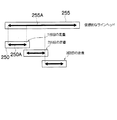
図21で説明したとおり、OD_β(α)>OD_α(β)となっている場合は、先にαを打滴すると、その上にβを重ねていくほど、インクの最表面で、α波長領域の光が表面反射してしまい、αの濃度が下がってくる。したがってこの場合はβ→αの順に打滴するものとする。一例として、図1にCインクとMインクの比較例を示す。 As described in FIG. 21, when OD_β (α)> OD_α (β), when α is first ejected, the more the β is superimposed on the α, the more the α wavelength region is on the outermost surface of the ink. Light is reflected on the surface, and the density of α decreases. Therefore, in this case, droplets are ejected in the order of β → α. As an example, FIG. 1 shows a comparative example of C ink and M ink.
図1のように、CインクのM波長領域の反射濃度OD_M(C)とMインクのC波長領域の反射濃度OD_C(M)の大小を比較し(ステップS10)、OD_C(M)>OD_M(C)の関係を満たしていたら、C→Mの順に打滴するものとする(ステップS12)。その一方、ステップS10の判定において、OD_C(M)<OD_M(C)の関係を満たしていたら、M→Cの順に打滴するものとする(ステップS14)。 As shown in FIG. 1, the reflection density OD_M (C) of the M ink in the M wavelength region and the reflection density OD_C (M) of the M ink in the C wavelength region are compared (step S10), and OD_C (M)> OD_M ( If the relationship of C) is satisfied, droplets are ejected in the order of C → M (step S12). On the other hand, if it is determined in step S10 that the relationship OD_C (M) <OD_M (C) is satisfied, droplets are ejected in the order of M → C (step S14).
図2(a)は、OD_M(C)<OD_C(M)の関係を満たす場合の反射の模式図、図2(b)は、OD_M(C)>OD_C(M)の関係を満たす場合の反射の模式図である。図中符号C,Mはそれぞれ記録媒体上に打滴されたシアン(C),マゼンタ(M)のインクを表し、Cインク,Mインクからの矢印の長さは反射光の光量を表している。 2A is a schematic diagram of reflection when the relationship of OD_M (C) <OD_C (M) is satisfied, and FIG. 2B is a reflection when the relationship of OD_M (C)> OD_C (M) is satisfied. FIG. Reference numerals C and M in the figure represent cyan (C) and magenta (M) inks deposited on the recording medium, respectively, and the lengths of the arrows from the C ink and M ink represent the amount of reflected light. .
CインクとMインクの組み合わせ以外の、他の2色の組み合わせ(「MとY」、「YとC」)においても、同様に、打滴順を決めることができる。 In the other two-color combinations (“M and Y”, “Y and C”) other than the combination of C ink and M ink, the droplet ejection order can be determined in the same manner.
CとM、MとY、YとCの各組についてそれぞれ打滴順を決めると、全ての組み合わせは図3の表に示した8通り((a) 〜(h))となる。同表で(b) 〜(g) の場合については、CMYの打滴順(シングルパスの場合、各色のヘッド配置順)はそれぞれ表中に示したとおり一意に定まる。 When the droplet ejection order is determined for each of the combinations of C and M, M and Y, and Y and C, all combinations are eight ((a) to (h)) shown in the table of FIG. In the case of (b) to (g) in the same table, the CMY droplet ejection order (in the case of single pass, the order of head placement of each color) is uniquely determined as shown in the table.
しかし、図3の表に示した(a),(h)の場合は、CとM、MとY、YとCの各組で決めた打滴順がいわゆる「三すくみ」の関係になっているため、上記の手法ではC, M, Yの打滴順が一意に決まらない。このときは、以下に示す(手順3)の手法に従って打滴順を決定する。 However, in the case of (a) and (h) shown in the table of FIG. 3, the droplet ejection order determined for each set of C and M, M and Y, and Y and C has a so-called “three-shrink” relationship. For this reason, the above-described method does not uniquely determine the order of C, M, and Y ejection. At this time, the droplet ejection order is determined according to the following procedure (Procedure 3).
(手順1−3)上記した「三すくみ」の場合には、評価に用いた3つの不等式のうち、差が大きい上位2つの結果から打滴順を定めるものとする。表記の便宜上、OD_α(β)−OD_β(α)=Δ(αβ)と表すことにする。例えば、図に示した表の(a) において、各組(CとM、MとY、YとC)の不等式における左辺と右辺の差Δ(CM)、Δ(MY)、Δ(YC)について、Δ(CM)>Δ(MY)>Δ(YC)となっていたとすると、差が大きい上記2組である、CとM、MとYの結果を採用し(すなわち、差の最も小さいYとCの結果を無視して)、打滴順は下から(記録媒体に近い方から)C→M→Yと決定する。 (Procedure 1-3) In the case of the “three-way”, the droplet ejection order is determined from the top two results having the largest differences among the three inequalities used in the evaluation. For convenience of description, OD_α (β) −OD_β (α) = Δ (αβ) will be expressed. For example, in (a) of the table shown in the figure, the difference Δ (CM), Δ (MY), Δ (YC) between the left side and the right side in the inequality of each pair (C and M, M and Y, Y and C) If Δ (CM)> Δ (MY)> Δ (YC), the results of C and M and M and Y, which are the above two sets having a large difference, are adopted (that is, the difference is the smallest). Ignoring the results of Y and C), the droplet ejection order is determined from the bottom (from the side closer to the recording medium) as C → M → Y.
一例として、表の(a) の場合について、打滴順の決定フローを図4に示す。図示のように、まず、Δ(CM)、Δ(MY)、Δ(YC)を求め(ステップS20)、これらのうち最小のものを判断する(ステップS22)。ステップS22でΔ(CM)が最小であると判定したら、CとMの結果を無視して残り2組の結果を採用し、打滴順をM→Y→Cの順とする(ステップS24)。また、ステップS22でΔ(MY)が最小であると判定したら、MとYの結果を無視して残り2組の結果を採用し、打滴順をY→C→Mの順とする(ステップS26)。或いはまた、ステップS22でΔ(YC)が最小であると判定したら、YとCの結果を無視して残り2組の結果を採用し、打滴順をC→M→Yの順とする(ステップS28)。 As an example, FIG. 4 shows a flow for determining the droplet ejection order in the case of (a) in the table. As shown in the figure, first, Δ (CM), Δ (MY), Δ (YC) are obtained (step S20), and the smallest of these is determined (step S22). If it is determined in step S22 that Δ (CM) is minimum, the results of C and M are ignored and the remaining two sets of results are adopted, and the droplet ejection order is M → Y → C (step S24). . If it is determined in step S22 that Δ (MY) is minimum, the results of M and Y are ignored and the remaining two sets of results are adopted, and the droplet ejection order is set in the order of Y → C → M (step). S26). Alternatively, if Δ (YC) is determined to be the smallest in step S22, the results of Y and C are ignored and the remaining two sets of results are adopted, and the droplet ejection order is set in the order of C → M → Y ( Step S28).
なお、本発明においては、ブラックの打滴順は特に限定しないものとする。 In the present invention, the order of black droplet ejection is not particularly limited.
以上説明したように、単色の反射濃度において、他の色の波長領域の反射濃度が大きい色材を後で打滴する。シングルパス方式のインクジェット記録装置の場合には、CMYヘッドの並び順に関して、単色の反射濃度において、他の色の波長領域の反射濃度が大きい色材を吐出するためのヘッドを後(下流側)に配置する。これにより、同じインク、同じ打滴量で、より高濃度(広い色再現域)の画像を形成することが可能になる。 As described above, a color material having a high reflection density in the wavelength region of other colors at a single color reflection density is ejected later. In the case of a single-pass inkjet recording apparatus, with respect to the order of arrangement of the CMY heads, the head for discharging a color material having a large reflection density in the wavelength region of other colors in the single-color reflection density is located behind (downstream side). To place. As a result, it is possible to form an image with a higher density (wide color reproduction range) with the same ink and the same droplet ejection amount.
〔第2の実施形態:重ね打ちによる2次色の反射濃度から打滴順を決める方法〕
シアン(C),マゼンタ(M),イエロー(Y)の3色のインクについて、2色の重ね打ちによる2次色の反射濃度から打滴順を決定する方法は以下の(手順2−1)〜(手順2−3)による。
[Second Embodiment: Method of Determining Droplet Order from Secondary Color Reflection Density by Overprinting]
The method of determining the droplet ejection order from the secondary color reflection density by two-color overstrike for cyan (C), magenta (M), and yellow (Y) inks is as follows (procedure 2-1). To (Procedure 2-3).
(手順2−1)C,M,Yインクのうち任意の2色(α,βとする)について、α→βの順で打滴したサンプルと、β→αの順で打滴したサンプルの反射濃度(α波長領域、β波長領域)を測定する。ただし、各サンプルにおける単位面積当たりの打滴量は、単位面積に想定される最大打ち込み量の1/2とする。 (Procedure 2-1) Samples deposited in the order of α → β and samples deposited in the order of β → α for any two colors of C, M, Y ink (assumed α, β) The reflection density (α wavelength region, β wavelength region) is measured. However, the droplet ejection amount per unit area in each sample is ½ of the maximum implantation amount assumed for the unit area.
(手順2−2)上記の手順2−1で得られた値について、横軸にα波長領域の濃度(OD_α)、縦軸にβ波長領域の濃度(OD_β)をとってプロットすると、その相対的な位置関係は図5の(A)〜(D)の何れかになる。図中黒丸印(●)は、α→βの順で打滴したサンプルの測定値を示し、黒三角印(▲)は、β→αの順で打滴したサンプルの測定値を示す。 (Procedure 2-2) When the values obtained in the above procedure 2-1 are plotted with the concentration in the α wavelength region (OD_α) on the horizontal axis and the concentration in the β wavelength region (OD_β) on the vertical axis, the relative values are plotted. The general positional relationship is any one of (A) to (D) in FIG. In the figure, black circles (●) indicate measured values of samples deposited in the order of α → β, and black triangles (▲) indicate measured values of samples ejected in the order of β → α.
図5(A)の場合は、β→αの順で打滴した方が、α→βの順で打滴するよりもα波長領域、β波長領域の濃度とも大きくなっているので、この場合は、β→αの順で打滴するものとする。 In the case of FIG. 5 (A), when the droplets are ejected in the order of β → α, the concentrations in the α wavelength region and the β wavelength region are larger than the droplets ejected in the order of α → β. Is assumed to be ejected in the order of β → α.
図5(C)の場合も、(A)と同様の考え方で、このときはα→βの順で打滴するものとする。 In the case of FIG. 5C as well, it is assumed that droplets are ejected in the order of α → β in the same way as in FIG.
図5(B)の場合は、それぞれ先に打たれた(下にある)色の濃度が小さくなっている。このときは単色(αのみ、又はβのみ)の濃度と比べて、その色が下に打たれたときの濃度の変化値(減少値)が小さい方の順序で打滴するものとする。例えば、
OD_α(α)−OD_α(α→β)>OD_β(β)−OD_β(β→α)…式[2]
となった場合には、β→αの順で打滴する。
In the case of FIG. 5B, the density of the first hit color (below) is low. In this case, it is assumed that droplets are ejected in the order in which the change value (decrease value) of the density when the color is hit down is smaller than the density of a single color (α only or β only). For example,
OD_α (α) −OD_α (α → β)> OD_β (β) −OD_β (β → α) (2)
In this case, droplets are ejected in the order of β → α.
図5(D)の場合は、それぞれ後に打たれた(上にある)色の濃度が小さくなっている。このような状況になることは、通常考え難いが、仮にこのような状況になった場合は、単色(αのみ、又はβのみ)の濃度と比べて、その色が上に打たれたときの濃度の変化値(減少値)が小さい方の順序で打滴するものとする。例えば、
OD_α(α)−OD_α(β→α)>OD_β(β)−OD_β(α→β)…式[3]
となった場合には、α→βの順で打滴する。一例として、C(シアン)とM(マゼンタ)の場合の打滴順決定フローを図6に示す。
In the case of FIG. 5D, the density of each of the colors hit later (on the top) is small. It is usually difficult to think of this situation, but if such a situation occurs, compared to the density of a single color (alpha only or beta only), when the color is struck above It is assumed that droplets are ejected in the order of smaller density change value (decrease value). For example,
OD_α (α) −OD_α (β → α)> OD_β (β) −OD_β (α → β) (3)
In this case, droplets are ejected in the order of α → β. As an example, FIG. 6 shows a droplet ejection order determination flow for C (cyan) and M (magenta).
図6に示したように、まず、C→M,M→Cの順でそれぞれ打滴したときのC,Mの濃度が図5に示した(A)〜(D)のどのパターンに該当するかを判定する(ステップS30)。判定の結果(A)のパターンに該当する場合には、M→Cの順に打滴するものとする(ステップS32)。また、ステップS30の判定の結果、(C)のパターンに該当する場合は、C→Mの順に打滴するものとする(ステップS34)。 As shown in FIG. 6, first, the density of C and M when droplets are ejected in the order of C.fwdarw.M and M.fwdarw.C corresponds to any of the patterns (A) to (D) shown in FIG. Is determined (step S30). If the pattern corresponds to the determination result (A), droplets are ejected in the order of M → C (step S32). If the result of determination in step S30 corresponds to the pattern (C), droplets are ejected in the order of C → M (step S34).
ステップS30の判定の結果、(B)のパターンに該当する場合は、ステップS36に進む。ステップS36では、OD_C(C)−OD_C(C→M)とOD_M(M)−OD_M(M→C)の大小関係を比較し、小さい方を判定する。当該判定の結果、OD_C(C)−OD_C(C→M)の方が小さければ、C→Mの順に打滴するものとする(ステップS38)。また、ステップS36における判定の結果、OD_M(M)−OD_M(M→C)の方が小さければ、M→Cの順に打滴するものとする(ステップS40)。 If the result of determination in step S30 is that it corresponds to the pattern (B), the process proceeds to step S36. In step S36, the magnitude relationship between OD_C (C) -OD_C (C → M) and OD_M (M) -OD_M (M → C) is compared, and the smaller one is determined. As a result of the determination, if OD_C (C) −OD_C (C → M) is smaller, droplets are ejected in the order of C → M (step S38). If the result of determination in step S36 is that OD_M (M) −OD_M (M → C) is smaller, droplets are ejected in the order of M → C (step S40).
ステップS30の判定の結果、(D)のパターンに該当する場合は、ステップS42に進む。ステップS42では、OD_C(C)−OD_C(M→C)とOD_M(M)−OD_M(C→M)の大小関係を比較し、小さい方を判定する。当該判定の結果、OD_C(C)−OD_C(M→C)の方が小さければ、M→Cの順に打滴するものとする(ステップS44)。また、ステップS42における判定の結果、OD_M(M)−OD_M(C→M)の方が小さければ、C→Mの順に打滴するものとする(ステップS46)。 If the result of determination in step S30 is that it corresponds to the pattern (D), the process proceeds to step S42. In step S42, the magnitude relationship between OD_C (C) -OD_C (M → C) and OD_M (M) -OD_M (C → M) is compared, and the smaller one is determined. As a result of the determination, if OD_C (C) −OD_C (M → C) is smaller, droplets are ejected in the order of M → C (step S44). If the result of determination in step S42 is that OD_M (M) −OD_M (C → M) is smaller, droplets are ejected in the order C → M (step S46).
(手順2−3) 上記の手順2−1、2−2で説明したことを、CとM、MとY、YとCの各組で行い、CとM、MとY、YとCの打滴順を決定する。その結果、取り得る打滴順は、図7の表に示される8通り((a) 〜(h) )である。 (Procedure 2-3) The above-described procedures 2-1 and 2-2 are performed for each set of C and M, M and Y, and Y and C. C and M, M and Y, Y and C Determine the order of droplet ejection. As a result, there are eight possible droplet ejection orders ((a) to (h)) shown in the table of FIG.
3色の打滴順が一意に決定される場合(図の表に示した(b)〜(g) の場合)は、その順に従って打滴を行うものとする。 When the three-color droplet ejection order is uniquely determined (in the case of (b) to (g) shown in the table of the figure), the droplet ejection is performed according to the order.
(手順2−4) 図7の表に示した(a),(h) のように、打滴順が一意に決まらない場合(「三すくみ」の場合)については、3 つの組のうち、どれか1 つの結果を無視して打滴順を決めることになる。このときは、手順2−3で決めた打滴順で打滴したときと、その逆の打滴順で打滴したときとの、濃度からの変化値(減少値)が大きい2組の結果を採用するものとする。例えば、図7の(a) の場合には、以下の手順<1.>〜<3.>に従って打滴順序を決める。 (Procedure 2-4) As in (a) and (h) shown in the table of Fig. 7, if the droplet ejection order is not uniquely determined (in the case of "three strokes"), which of the three sets I will ignore the one result and decide the order of droplets. In this case, two sets of results having a large change value (decrease value) from the density when the droplets are ejected in the droplet ejection order determined in Procedure 2-3 and when the droplets are ejected in the reverse droplet ejection order. Shall be adopted. For example, in the case of FIG. 7A, the droplet ejection order is determined according to the following procedures <1.> to <3.>.
なお、ΔOD_α(αβ)=OD_α(α→β)−OD_α(β→α)と表すことにし、ここで2色の組み合わせは、(α,β)=(C,M),(M,Y),(Y,C)である。 Note that ΔOD_α (αβ) = OD_α (α → β) −OD_α (β → α), where the combination of the two colors is (α, β) = (C, M), (M, Y) , (Y, C).
<1.>まず、ΔOD_C(CM),ΔOD_M(CM),ΔOD_M(MY),ΔOD_Y(MY),ΔOD_Y(YC),OD_C(YC)の各値を求める。 <1.> First, ΔOD_C (CM), ΔOD_M (CM), ΔOD_M (MY), ΔOD_Y (MY), ΔOD_Y (YC), and OD_C (YC) are obtained.
<2.>次に、OD_C(CM)とOD_M(CM)で大きい方の値(これをΔOD(CM)とする)、OD_M(MY)とOD_Y(MY)で大きい方の値(これをΔOD(MY)とする)、OD_Y(YC)とOD_C(YC)で大きい方の値(これをΔOD(YC)とする)、をそれぞれ求める。 <2.> Next, the larger value of OD_C (CM) and OD_M (CM) (this is ΔOD (CM)), and the larger value of OD_M (MY) and OD_Y (MY) (this is ΔOD (MY)), and OD_Y (YC) and OD_C (YC), whichever is larger (this is referred to as ΔOD (YC)).
<3.>上記の<2.>で求めたΔOD(CM),ΔOD(MY),ΔOD(YC)で値が大きい2組の結果を採用する。例えば、
ΔOD(CM)>ΔOD(MY)>ΔOD(YC)…式[4]
となった場合は、CとM、MとYの打滴順を考慮し、C→M→Yの順で打滴するものとする。
<3.> Two sets of results having large values in ΔOD (CM), ΔOD (MY), and ΔOD (YC) obtained in <2.> above are adopted. For example,
ΔOD (CM)> ΔOD (MY)> ΔOD (YC) (4)
In this case, it is assumed that droplets are ejected in the order of C → M → Y in consideration of the droplet ejection order of C and M and M and Y.
一例として、図7の(a) の場合のときの打滴順決定フローを図8に示す。 As an example, FIG. 8 shows a droplet ejection order determination flow in the case of FIG.
図8に示したように、まず、ΔOD(CM),ΔOD(MY),OD(YC)を求め(ステップS50)、これらの中で最小のものを判定する(ステップS52)。ΔOD(CM)が最小の場合は、他の上位2組の打滴順を優先して、M→Y→Cの順に打滴するものとする(ステップS54)。ステップS52の判定において、ΔOD(MY)が最小の場合は、他の上位2組の打滴順を優先して、Y→C→Mの順に打滴するものとする(ステップS56)。ステップS52の判定において、ΔOD(YC)が最小の場合は、他の上位2組の打滴順を優先して、C→M→Yの順に打滴するものとする(ステップS58)。 As shown in FIG. 8, first, ΔOD (CM), ΔOD (MY), and OD (YC) are obtained (step S50), and the smallest one is determined (step S52). If ΔOD (CM) is the minimum, the droplets are ejected in the order of M → Y → C, giving priority to the other two top droplet ejection orders (step S54). If ΔOD (MY) is the smallest in the determination in step S52, the droplets are ejected in the order of Y → C → M with priority given to the other two sets of droplet ejection order (step S56). If ΔOD (YC) is the smallest in the determination in step S52, the droplets are ejected in the order of C → M → Y with priority given to the other two sets of droplet ejection order (step S58).
図7の(h)の場合についても、上述の(a) の場合と同様の考え方で処理することができる。なお、本発明においては、ブラックの打滴順は特に限定しないものとする。 The case of (h) in FIG. 7 can be processed in the same way as in the case of (a) described above. In the present invention, the order of black droplet ejection is not particularly limited.
以上説明したように、CMYの任意の2色の組について、互いに重ねたときの濃度がより大きくなるように、インクの打滴順(重ね順)を決定する。 As described above, the ink ejection order (overlapping order) is determined so that the density of two arbitrary CMY colors when they are superimposed on each other is higher.
シングルパス方式のインクジェット記録装置の場合は、上記の手法によって決定した打滴順にしたがってヘッドの配置順が設計される。すなわち、記録媒体の搬送方向について上流側から打滴順番の色順に下流に向かって各色のヘッドが配置される。これにより、同じインク、同じ打滴量で、より高濃度(広い色再現域)の画像を形成することことが可能になる。 In the case of a single-pass inkjet recording apparatus, the head arrangement order is designed according to the droplet ejection order determined by the above-described method. That is, the heads of the respective colors are arranged from the upstream side toward the downstream in the color order of the droplet ejection order in the recording medium conveyance direction. This makes it possible to form an image with a higher density (wide color reproduction range) with the same ink and the same droplet ejection amount.
もちろん、上記手法によって決定した打滴順は、シングルパス方式のインクジェット記録装置に適用される場合に限定されず、シャトルスキャン方式のインクジェット記録装置にも適用可能である。 Of course, the droplet ejection order determined by the above method is not limited to the case of being applied to a single-pass inkjet recording apparatus, and can also be applied to a shuttle scan inkjet recording apparatus.
上述した各実施形態によるカラーインクの打滴順決定方法はコンピュータを用いて実施することができる。すなわち、上述したカラーインクの打滴順決定方法のアルゴリズムをコンピュータに実行させるプログラム(打滴順決定処理プログラム)を作成し、このプログラムによってコンピュータを動作させることにより、当該コンピュータをカラーインクの打滴順決定装置として機能させることができる。 The color ink droplet ejection order determination method according to each of the above-described embodiments can be implemented using a computer. That is, a program (droplet order determination processing program) for causing a computer to execute the algorithm of the above-described color ink droplet ejection order determination method is created, and the computer is operated by this program, thereby causing the computer to perform color ink droplet ejection order. It can function as an order determination device.
図9はコンピュータのシステム構成例を示すブロック図である。コンピュータ10は、本体12と、ディスプレイ(表示手段)14及びキーボードやマウスなど入力装置(各種の指示を入力するための入力手段)16から構成される。本体12内には中央演算処理装置(CPU)20、RAM22、ROM24、入力装置16からの信号入力を制御する入力制御部26、ディスプレイ14に対して表示用の信号を出力する表示制御部28、ハードディスク装置30、通信インターフェース32、及びメディアインターフェース34などを有し、これら各回路はバス36を介して相互に接続されている。
FIG. 9 is a block diagram illustrating a system configuration example of a computer. The
CPU20は、全体の制御装置及び演算装置(演算手段)として機能する。RAM22は、データの一時記憶領域やCPU20によるプログラム実行時の作業用領域として利用される。ROM24は、CPU20を動作させるブートプログラムや各種設定値・ネットワーク接続情報などを記憶する書き換え可能な不揮発性の記憶手段である。ハードディスク装置30には、オペレーティングシステム(OS)や各種のアプリケーションソフト(プログラム)やデータ等が格納される。
The
通信インターフェース32は、USB(Universal Serial Bus)やLAN、Bluetooth(登録商標)など所定の通信方式に従って外部機器や通信ネットワークに接続するための手段である。本例では、通信インターフェース32を介して光学濃度計37を接続することができる。光学濃度計37は、打滴サンプルの反射濃度を測定し、その測定値のデータを出力する。メディアインターフェース34は、メモリカードや磁気ディスク、光磁気ディスク、光ディスクに代表される外部記憶装置38の読み書き制御を行う手段である。
The
単色インクの反射濃度や2次色の反射濃度の情報は、光学濃度計37を用いて実際に反射濃度を測定することによって取得してもよいし、予め実験等によって把握した値を入力装置16から入力したり、通信インターフェース32やメディアインターフェース34を介して取得したりしてもよい。
Information on the reflection density of the single color ink and the reflection density of the secondary color may be acquired by actually measuring the reflection density using the
本発明によるカラーインクの打滴順決定処理プログラムは、ハードディスク装置30、或いは外部記憶装置38に格納されており、必要に応じて当該プログラムが読み出され、RAM22に展開されて実行される。或いは、通信インターフェース32を介して接続される不図示のネットワーク上に設置されたサーバによってプログラムが提供される態様も可能であるし、インターネット上のサーバによって本プログラムによる演算処理サービスを提供するという態様も考えられる。
The color ink droplet ejection order determination processing program according to the present invention is stored in the
オペレータは、ディスプレイ14上に表示される不図示のアプリケーションウインドウを見ながら入力装置16を操作して演算条件や初期値などの設定を入力することができるとともに、演算結果をディスプレイ14上で確認することができる。
The operator can input settings such as calculation conditions and initial values by operating the
次に、本発明のカラーインクの打滴順決定方法によって決定された打滴順序の結果を利用して設計されたインクジェット記録装置の例を説明する。 Next, an example of an ink jet recording apparatus designed using the result of the droplet ejection order determined by the color ink droplet ejection order determination method of the present invention will be described.
〔インクジェット記録装置の全体構成〕
図10は本発明に係る画像形成装置の一実施形態を示すインクジェット記録装置の全体構成図である。ここでは、C→M→Yの順で打滴すべき旨の決定結果に基づいて設計された装置例を述べる。同図に示すように、このインクジェット記録装置110は、黒(K),シアン(C),マゼンタ(M),イエロー(Y)の各インクに対応して設けられた複数のインクジェット記録ヘッド(以下、ヘッドという。)112K,112C,112M,112Yを有する印字部112と、各ヘッド112K,112C,112M,112Yに供給するインクを貯蔵しておくインク貯蔵/装填部114と、記録媒体たる記録紙116を供給する給紙部118と、記録紙116のカールを除去するデカール処理部120と、前記印字部112のノズル面(インク吐出面)に対向して配置され、記録紙116の平面性を保持しながら記録紙116を搬送するベルト搬送部122と、印字部112による印字結果を読み取る印字検出部124と、記録済みの記録紙(プリント物)を外部に排紙する排紙部126とを備えている。
[Overall configuration of inkjet recording apparatus]
FIG. 10 is an overall configuration diagram of an ink jet recording apparatus showing an embodiment of an image forming apparatus according to the present invention. Here, an example of an apparatus designed based on the determination result that droplets should be ejected in the order of C → M → Y will be described. As shown in the figure, the ink
インク貯蔵/装填部114は、各ヘッド112K,112C,112M,112Yに対応する色のインクを貯蔵するインクタンクを有し、各タンクは所要の管路を介してヘッド112K,112C,112M,112Yと連通されている。また、インク貯蔵/装填部114は、インク残量が少なくなるとその旨を報知する報知手段(表示手段、警告音発生手段)を備えるとともに、色間の誤装填を防止するための機構を有している。
The ink storage /
図10では、給紙部18の一例としてロール紙(連続用紙)のマガジンが示されているが、紙幅や紙質等が異なる複数のマガジンを併設してもよい。また、ロール紙のマガジンに代えて、又はこれと併用して、カット紙が積層装填されたカセットによって用紙を供給してもよい。 In FIG. 10, a magazine for rolled paper (continuous paper) is shown as an example of the paper supply unit 18, but a plurality of magazines having different paper widths, paper quality, and the like may be provided side by side. Further, instead of the roll paper magazine or in combination therewith, the paper may be supplied by a cassette in which cut papers are stacked and loaded.
複数種類の記録媒体(メディア)を利用可能な構成にした場合、メディアの種類情報を記録したバーコード或いは無線タグなどの情報記録体をマガジンに取り付け、その情報記録体の情報を所定の読取装置によって読み取ることで、使用される記録媒体の種類(メディア種)を自動的に判別し、メディア種に応じて適切なインク吐出を実現するようにインク吐出制御を行うことが好ましい。 When a plurality of types of recording media (media) can be used, an information recording body such as a barcode or a wireless tag that records media type information is attached to a magazine, and information on the information recording body is read by a predetermined reader. It is preferable to automatically determine the type of recording medium to be used (media type) and to perform ink ejection control so as to realize appropriate ink ejection according to the media type.
給紙部118から送り出される記録紙116はマガジンに装填されていたことによる巻きクセが残り、カールする。このカールを除去するために、デカール処理部120においてマガジンの巻きクセ方向と逆方向に加熱ドラム130で記録紙116に熱を与える。このとき、多少印字面が外側に弱いカールとなるように加熱温度を制御するとより好ましい。
The
ロール紙を使用する装置構成の場合、図10のように、裁断用のカッター(第1のカッター)128が設けられており、該カッター128によってロール紙は所望のサイズにカットされる。なお、カット紙を使用する場合には、カッター128は不要である。
In the case of an apparatus configuration using roll paper, a cutter (first cutter) 128 is provided as shown in FIG. 10, and the roll paper is cut into a desired size by the
デカール処理後、カットされた記録紙116は、ベルト搬送部122へと送られる。ベルト搬送部122は、ローラ131、132間に無端状のベルト133が巻き掛けられた構造を有し、少なくとも印字部112のノズル面及び印字検出部124のセンサ面に対向する部分が水平面(フラット面)をなすように構成されている。
After the decurling process, the
ベルト133は、記録紙116の幅よりも広い幅寸法を有しており、ベルト面には多数の吸引穴(不図示)が形成されている。図10に示したとおり、ローラ131、132間に掛け渡されたベルト133の内側において印字部112のノズル面及び印字検出部124のセンサ面に対向する位置には吸着チャンバ134が設けられており、この吸着チャンバ134をファン135で吸引して負圧にすることによって記録紙116がベルト133上に吸着保持される。なお、吸引吸着方式に代えて、静電吸着方式を採用してもよい。
The
ベルト133が巻かれているローラ131、132の少なくとも一方にモータ(図15中符号188)の動力が伝達されることにより、ベルト133は図10上の時計回り方向に駆動され、ベルト133上に保持された記録紙116は図10の左から右へと搬送される。
When the power of the motor (
縁無しプリント等を印字するとベルト133上にもインクが付着するので、ベルト133の外側の所定位置(印字領域以外の適当な位置)にベルト清掃部136が設けられている。ベルト清掃部136の構成について詳細は図示しないが、例えば、ブラシ・ロール、吸水ロール等をニップする方式、清浄エアーを吹き掛けるエアーブロー方式、或いはこれらの組合せなどがある。清掃用ロールをニップする方式の場合、ベルト線速度とローラ線速度を変えると清掃効果が大きい。
Since ink adheres to the
なお、ベルト搬送部122に代えて、ローラ・ニップ搬送機構を用いる態様も考えられるが、印字領域をローラ・ニップ搬送すると、印字直後に用紙の印字面をローラが接触するので画像が滲み易いという問題がある。したがって、本例のように、印字領域では画像面を接触させない吸着ベルト搬送が好ましい。
Although a mode using a roller / nip conveyance mechanism in place of the
ベルト搬送部122により形成される用紙搬送路上において印字部112の上流側には、加熱ファン140が設けられている。加熱ファン140は、印字前の記録紙116に加熱空気を吹き付け、記録紙116を加熱する。印字直前に記録紙116を加熱しておくことにより、インクが着弾後乾き易くなる。
A
印字部112の各ヘッド112K,112C,112M,112Yは、当該インクジェット記録装置110が対象とする記録紙116の最大紙幅に対応する長さを有し、そのノズル面には最大サイズの記録媒体の少なくとも一辺を超える長さ(描画可能範囲の全幅)にわたりインク吐出用のノズルが複数配列されたフルライン型のヘッドとなっている(図11参照)。
Each of the
ヘッド112K,112C,112M,112Yは、記録紙116の送り方向に沿って上流側から黒(K)、シアン(C)、マゼンタ(M)、イエロー(Y)の色順に配置され、それぞれのヘッド112K,112C,112M,112Yが記録紙116の搬送方向と略直交する方向に沿って延在するように固定設置される。
The
ベルト搬送部122により記録紙116を搬送しつつ各ヘッド112K,112C,112M,112Yからそれぞれ異色のインクを吐出することにより記録紙116上にカラー画像を形成し得る。
A color image can be formed on the
このように、紙幅の全域をカバーするノズル列を有するフルライン型のヘッド112K,112C,112M,112Yを色別に設ける構成によれば、紙送り方向(副走査方向)について記録紙116と印字部112を相対的に移動させる動作を1回行うだけで(すなわち1回の副走査で)、記録紙116の全面に画像を記録することができる。これにより、記録ヘッドが紙搬送方向と直交する方向に往復動作するシャトル型ヘッドに比べて高速印字が可能であり、生産性を向上させることができる。
As described above, according to the configuration in which the full-line heads 112K, 112C, 112M, and 112Y having nozzle rows that cover the entire width of the paper are provided for each color, the
本例では、KCMYの標準色(4色)の構成を例示したが、インク色や色数の組合せについては本実施形態に限定されず、必要に応じて淡インク、濃インク、特別色インクを追加してもよい。例えば、ライトシアン、ライトマゼンタなどのライト系インクを吐出するインクジェットヘッドを追加する構成も可能である。また、各色ヘッドの配置順序は、図1乃至図9で説明したカラーインクの打滴順決定方法による決定結果に従う。 In this example, the configuration of KCMY standard colors (four colors) is illustrated, but the combination of ink colors and the number of colors is not limited to this embodiment, and light ink, dark ink, and special color ink are used as necessary. May be added. For example, it is possible to add an ink jet head that discharges light ink such as light cyan and light magenta. Further, the arrangement order of the color heads follows the determination result obtained by the method for determining the color ink droplet ejection order described with reference to FIGS.
図10に示した印字検出部124は、印字部112の打滴結果を撮像するためのイメージセンサ(ラインセンサ又はエリアセンサ)を含み、該イメージセンサによって読み取った打滴画像からノズルの目詰まりや着弾位置ずれなどの吐出不良をチェックする手段として機能する。各色のヘッド112K,112C,112M,112Yにより印字されたテストパターン又は実技画像が印字検出部124により読み取られ、各ヘッドの吐出判定が行われる。吐出判定は、吐出の有無、ドットサイズの測定、ドット着弾位置の測定などで構成される。この印字検出部124は打滴サンプルの光学濃度を測定する手段として兼用することもできる。
The
印字検出部124の後段には後乾燥部142が設けられている。後乾燥部142は、印字された画像面を乾燥させる手段であり、例えば、加熱ファンが用いられる。印字後のインクが乾燥するまでは印字面と接触することは避けたほうが好ましいので、熱風を吹き付ける方式が好ましい。
A
多孔質のペーパーに染料系インクで印字した場合などでは、加圧によりペーパーの孔を塞ぐことでオゾンなど、染料分子を壊す原因となるものと接触することを防ぐことで画像の耐候性がアップする効果がある。 When printing on porous paper with dye-based ink, the weather resistance of the image is improved by preventing contact with ozone or other things that cause dye molecules to break by pressurizing the paper holes with pressure. There is an effect to.
後乾燥部142の後段には、加熱・加圧部144が設けられている。加熱・加圧部144は、画像表面の光沢度を制御するための手段であり、画像面を加熱しながら所定の表面凹凸形状を有する加圧ローラ145で加圧し、画像面に凹凸形状を転写する。
A heating /
こうして生成されたプリント物は排紙部126から排出される。本来プリントすべき本画像(目的の画像を印刷したもの)とテスト印字とは分けて排出することが好ましい。このインクジェット記録装置110では、本画像のプリント物と、テスト印字のプリント物とを選別してそれぞれの排出部126A、126Bへと送るために排紙経路を切り換える不図示の選別手段が設けられている。なお、大きめの用紙に本画像とテスト印字とを同時に並列に形成する場合は、カッター(第2のカッター)148によってテスト印字の部分を切り離す。また、図10には示さないが、本画像の排出部126Aには、オーダー別に画像を集積するソーターが設けられる。
The printed matter generated in this manner is outputted from the
〔ヘッドの構造〕
次に、ヘッドの構造について説明する。色別の各ヘッド112K,112C,112M,112Yの構造は共通しているので、以下、これらを代表して符号150によってヘッドを示すものとする。
[Head structure]
Next, the structure of the head will be described. Since the structures of the
図12(a) はヘッド150の構造例を示す平面透視図であり、図12(b) はその一部の拡大図である。また、図12(c) はヘッド150の他の構造例を示す平面透視図、図13は1つの液滴吐出素子(1つのノズル151に対応したインク室ユニット)の立体的構成を示す断面図(図12(a) 中の13−13線に沿う断面図)である。
12A is a plan perspective view showing an example of the structure of the
記録紙116上に印字されるドットピッチを高密度化するためには、ヘッド150におけるノズルピッチを高密度化する必要がある。本例のヘッド150は、図12(a),(b) に示したように、インク吐出口であるノズル151と、各ノズル151に対応する圧力室152等からなる複数のインク室ユニット(液滴吐出素子)153を千鳥でマトリクス状に(2次元的に)配置させた構造を有し、これにより、ヘッド長手方向(紙送り方向と直交する方向)に沿って並ぶように投影される実質的なノズル間隔(投影ノズルピッチ)の高密度化を達成している。
In order to increase the dot pitch printed on the
記録紙116の送り方向と略直交する方向に記録紙116の全幅に対応する長さにわたり1列以上のノズル列を構成する形態は本例に限定されない。例えば、図12(a) の構成に代えて、図12(c) に示すように、複数のノズル151が2次元に配列された短尺のヘッドモジュール150’を千鳥状に配列して繋ぎ合わせることで記録紙116の全幅に対応する長さのノズル列を有するラインヘッドを構成してもよい。
The configuration in which one or more nozzle rows are formed over a length corresponding to the entire width of the
各ノズル151に対応して設けられている圧力室152は、その平面形状が概略正方形となっており(図12(a),(b) 参照)、対角線上の両隅部の一方にノズル151への流出口が設けられ、他方に供給インクの流入口(供給口)154が設けられている。なお、圧力室152の形状は、本例に限定されず、平面形状が四角形(菱形、長方形など)、五角形、六角形その他の多角形、円形、楕円形など、多様な形態があり得る。
The
図13に示したように、各圧力室152は供給口154を介して共通流路155と連通されている。共通流路155はインク供給源たるインクタンク(不図示)と連通しており、インクタンクから供給されるインクは共通流路155を介して各圧力室152に分配供給される。
As shown in FIG. 13, each
圧力室152の一部(図13において天面)を構成している加圧板(共通電極と兼用される振動板)156には個別電極157を備えたアクチュエータ158が接合されている。個別電極157と共通電極間に駆動電圧を印加することによってアクチュエータ158が変形して圧力室152の容積が変化し、これに伴う圧力変化によりノズル151からインクが吐出される。なお、アクチュエータ158には、チタン酸ジルコン酸鉛やチタン酸バリウムなどの圧電体を用いた圧電素子が好適に用いられる。インク吐出後、アクチュエータ158の変位が元に戻る際に、共通流路155から供給口154を通って新しいインクが圧力室152に供給される。
An
上述した構造を有するインク室ユニット153を図14に示す如く主走査方向に沿う行方向及び主走査方向に対して直交しない一定の角度θを有する斜めの列方向とに沿って一定の配列パターンで格子状に多数配列させることにより、本例の高密度ノズルヘッドが実現されている。
As shown in FIG. 14, the
すなわち、主走査方向に対してある角度θの方向に沿ってインク室ユニット153を一定のピッチdで複数配列する構造により、主走査方向に並ぶように投影されたノズルのピッチPはd× cosθとなり、主走査方向については、各ノズル151が一定のピッチPで直線状に配列されたものと等価的に取り扱うことができる。このような構成により、主走査方向に並ぶように投影されるノズル列が1インチ当たり2400個(2400ノズル/インチ)におよぶ高密度のノズル構成を実現することが可能になる。
That is, with a structure in which a plurality of
なお、印字可能幅の全幅に対応した長さのノズル列を有するフルラインヘッドで、ノズルを駆動する時には、(1)全ノズルを同時に駆動する、(2)ノズルを片方から他方に向かって順次駆動する、(3)ノズルをブロックに分割して、ブロックごとに片方から他方に向かって順次駆動する等が行われ、用紙の幅方向(用紙の搬送方向と直交する方向)に1ライン(1列のドットによるライン又は複数列のドットから成るライン)を印字するようなノズルの駆動を主走査と定義する。 When the nozzles are driven by a full line head having a nozzle row having a length corresponding to the entire printable width, (1) all the nozzles are driven simultaneously, (2) the nozzles are sequentially moved from one side to the other. (3) The nozzles are divided into blocks, and the nozzles are sequentially driven from one side to the other for each block, etc., and one line (1 in the width direction of the paper (direction perpendicular to the paper conveyance direction)) Driving a nozzle that prints a line of dots in a row or a line consisting of dots in a plurality of rows is defined as main scanning.
特に、図14に示すようなマトリクス状に配置されたノズル151を駆動する場合は、上記(3)のような主走査が好ましい。すなわち、ノズル151-11 、151-12 、151-13 、151-14 、151-15 、151-16 を1つのブロックとし(他にはノズル151-21 、…、151-26 を1つのブロック、ノズル151-31 、…、151-36 を1つのブロック、…として)、記録紙116の搬送速度に応じてノズル151-11 、151-12 、…、151-16 を順次駆動することで記録紙116の幅方向に1ラインを印字する。
In particular, when driving the
一方、上述したフルラインヘッドと用紙とを相対移動することによって、上述した主走査で形成された1ライン(1列のドットによるライン又は複数列のドットから成るライン)の印字を繰り返し行うことを副走査と定義する。 On the other hand, by relatively moving the above-mentioned full line head and the paper, printing of one line (a line formed by one line of dots or a line composed of a plurality of lines) formed by the above-described main scanning is repeatedly performed. This is defined as sub-scanning.
そして、上述の主走査によって記録される1ライン(或いは帯状領域の長手方向)の示す方向を主走査方向といい、上述の副走査を行う方向を副走査方向という。すなわち、本実施形態では、記録紙116の搬送方向が副走査方向であり、それに直交する方向が主走査方向ということになる。
The direction indicated by one line (or the longitudinal direction of the belt-like region) recorded by the main scanning is referred to as a main scanning direction, and the direction in which the sub scanning is performed is referred to as a sub scanning direction. In other words, in the present embodiment, the conveyance direction of the
本発明の実施に際してノズルの配置構造は図示の例に限定されない。また、本実施形態では、ピエゾ素子(圧電素子)に代表されるアクチュエータ158の変形によってインク滴を飛ばす方式が採用されているが、本発明の実施に際して、インクを吐出させる方式は特に限定されず、ピエゾジェット方式に代えて、ヒータなどの発熱体によってインクを加熱して気泡を発生させ、その圧力でインク滴を飛ばすサーマルジェット方式など、各種方式を適用できる。
In implementing the present invention, the nozzle arrangement structure is not limited to the illustrated example. In this embodiment, a method of ejecting ink droplets by deformation of an
〔制御系の説明〕
図15は、インクジェット記録装置110のシステム構成を示すブロック図である。同図に示したように、インクジェット記録装置110は、通信インターフェース170、システムコントローラ172、画像メモリ174、ROM175、モータドライバ176、ヒータドライバ178、プリント制御部180、画像バッファメモリ182、ヘッドドライバ184等を備えている。
[Explanation of control system]
FIG. 15 is a block diagram illustrating a system configuration of the
通信インターフェース170は、ホストコンピュータ186から送られてくる画像データを受信するインターフェース部である。通信インターフェース170にはUSB、IEEE1394、イーサネット(登録商標)、無線ネットワークなどのシリアルインターフェースやセントロニクスなどのパラレルインターフェースを適用することができる。この部分には、通信を高速化するためのバッファメモリ(不図示)を搭載してもよい。
The
ホストコンピュータ186から送出された画像データは通信インターフェース170を介してインクジェット記録装置110に取り込まれ、一旦画像メモリ174に記憶される。画像メモリ174は、通信インターフェース170を介して入力された画像を格納する記憶手段であり、システムコントローラ172を通じてデータの読み書きが行われる。画像メモリ174は、半導体素子からなるメモリに限らず、ハードディスクなど磁気媒体を用いてもよい。
Image data sent from the
システムコントローラ172は、中央演算処理装置(CPU)及びその周辺回路等から構成され、所定のプログラムに従ってインクジェット記録装置110の全体を制御する制御装置として機能するとともに、各種演算を行う演算装置として機能する。すなわち、システムコントローラ172は、通信インターフェース170、画像メモリ174、モータドライバ176、ヒータドライバ178等の各部を制御し、ホストコンピュータ186との間の通信制御、画像メモリ174及びROM175の読み書き制御等を行うとともに、搬送系のモータ188やヒータ189を制御する制御信号を生成する。
The
ROM175には、システムコントローラ172のCPUが実行するプログラム及び制御に必要な各種データなどが格納されている。ROM175は、書換不能な記憶手段であってもよいし、EEPROMのような書換可能な記憶手段であってもよい。画像メモリ174は、画像データの一時記憶領域として利用されるとともに、プログラムの展開領域及びCPUの演算作業領域としても利用される。
The
モータドライバ176は、システムコントローラ172からの指示に従って搬送系のモータ188を駆動するドライバ(駆動回路)である。ヒータドライバ178は、システムコントローラ172からの指示に従って後乾燥部142等のヒータ189を駆動するドライバである。
The
プリント制御部180は、システムコントローラ172の制御に従い、画像メモリ174内の画像データ(元画像のデータ) から印字制御用の信号を生成するための各種加工、補正などの処理を行う信号処理機能を有し、生成した印字データ(ドットデータ)をヘッドドライバ184に供給する制御部である。
The
プリント制御部180には画像バッファメモリ182が備えられており、プリント制御部180における画像データ処理時に画像データやパラメータなどのデータが画像バッファメモリ182に一時的に格納される。なお、図15において画像バッファメモリ182はプリント制御部180に付随する態様で示されているが、画像メモリ174と兼用することも可能である。また、プリント制御部180とシステムコントローラ172とを統合して1つのプロセッサで構成する態様も可能である。
The
画像入力から印字出力までの処理の流れを概説すると、印刷すべき画像のデータは、通信インターフェース170を介して外部から入力され、画像メモリ174に蓄えられる。この段階では、例えば、RGBの画像データが画像メモリ174に記憶される。
An outline of the flow of processing from image input to print output is as follows. Image data to be printed is input from the outside via the
インクジェット記録装置110では、インク(色材) による微細なドットの打滴密度やドットサイズを変えることによって、人の目に疑似的な連続階調の画像を形成するため、入力されたデジタル画像の階調(画像の濃淡)をできるだけ忠実に再現するようなドットパターンに変換する必要がある。そのため、画像メモリ174に蓄えられた元画像(RGB)のデータは、システムコントローラ172を介してプリント制御部180に送られ、該プリント制御部180においてディザ法や誤差拡散法などを用いたハーフトーン化処理によってインク色ごとのドットデータに変換される。
In the ink
すなわち、プリント制御部180は、入力されたRGB画像データをK,C,M,Yの4色のドットデータに変換する処理を行う。こうして、プリント制御部180で生成されたドットデータは、画像バッファメモリ182に蓄えられる。
That is, the
ヘッドドライバ184は、プリント制御部180から与えられる印字データ(すなわち、画像バッファメモリ182に記憶されたドットデータ)に基づき、ヘッド150の各ノズル151に対応するアクチュエータ158を駆動するための駆動信号を出力する。ヘッドドライバ184にはヘッドの駆動条件を一定に保つためのフィードバック制御系を含んでいてもよい。
The
ヘッドドライバ184から出力された駆動信号がヘッド150に加えられることによって、該当するノズル151からインクが吐出される。記録紙116の搬送速度に同期してヘッド150からのインク吐出を制御することにより、記録紙116上に画像が形成される。
When the drive signal output from the
上記のように、プリント制御部180における所要の信号処理を経て生成されたドットデータに基づき、ヘッドドライバ184を介して各ノズルからのインク液滴の吐出量や吐出タイミングの制御が行われる。これにより、所望のドットサイズやドット配置が実現される。
As described above, the ejection amount and ejection timing of ink droplets from each nozzle are controlled via the
印字検出部124は、図10で説明したように、イメージセンサを含むブロックであり、記録紙116に印字された画像を読み取り、所要の信号処理などを行って印字状況(吐出の有無、打滴のばらつき、光学濃度など)を検出し、その検出結果をプリント制御部180に提供する。なお、この印字検出部124に代えて、又はこれと組み合わせて他の吐出検出手段(吐出異常検出手段に相当)を設けてもよい。
As described with reference to FIG. 10, the
他の吐出検出手段としては、例えば、ヘッド150の各圧力室152内又はその近傍に圧力センサを設け、インク吐出時或いは圧力測定用のアクチュエータ駆動時などに、この圧力センサから得られる検出信号から吐出異常を検出する態様(内部検出方法)、或いは、レーザ発光素子などの光源と受光素子から成る光学検出系を用い、ノズルから吐出された液滴にレーザ光等の光を照射し、その透過光量(受光量)によって飛翔液滴を検出する態様(外部検出方法)などがあり得る。
As another ejection detection means, for example, a pressure sensor is provided in or near each
プリント制御部180は、必要に応じて印字検出部124或いは図示しない他の吐出検出手段から得られる情報に基づいてヘッド150に対する各種補正を行うとともに、必要に応じて予備吐出や吸引、ワイピング等のクリーニング動作(ノズル回復動作)を実施する制御を行う。
The
上記構成のインクジェット記録装置110によれば、インクの分光特性を考慮して、より高濃度の色再現が可能な打滴順序で記録が行われるようにヘッド配置順が設計されているため、広い色再現域の画像を形成することができる。
According to the ink
上記各実施形態では、記録媒体の全幅に対応する長さのノズル列を有するページワイドのフルライン型ヘッドを用いたインクジェット記録装置を説明したが、本発明の適用範囲はこれに限定されない。例えば、図16(a),(b)に示したように、記録媒体(記録紙116その他の印字媒体)216の幅Wm に足りない長さのラインヘッド(以下、印字ヘッド250という。)を用いて、複数回走査して画像形成する場合にも本発明は適用可能である。
In each of the above embodiments, an inkjet recording apparatus using a page-wide full-line head having a nozzle row having a length corresponding to the entire width of the recording medium has been described. However, the scope of application of the present invention is not limited to this. For example, as shown in FIGS. 16A and 16B, a line head (hereinafter referred to as a print head 250) having a length that is insufficient for the width Wm of the recording medium (
なお、図16(a),(b)の印字ヘッド250内に描いた両向き矢印250Aはノズル並び方向とノズル列の長さを模式的に表しており、白抜き矢印252は印字ヘッド走査方向を表している。図16(a)は、1回目の走査の様子を示し、同(b)は走査位置を変えて実施されるN回目(Nは2以上の整数)の走査の様子を示している。
Note that the double-headed
図示のとおり、印字ヘッド250は、その長手方向(ノズル並び方向)が記録媒体216の幅方向に沿って配置され、不図示のヘッド走査手段(キャリッジ、走行ガイドなどの支持機構及びこれを駆動するためのモータ等の駆動手段を含む。)によって印字ヘッド走査方向(白抜き矢印252方向)及び記録媒体216の幅方向(図16において横方向)に移動可能に支持されている。
As shown in the figure, the
記録媒体216の幅方向に対する印字ヘッド250の位置(走査位置)を変えながら、印字ヘッド走査方向252に複数回の走査を実施することによって、記録媒体216上に画像が形成される。
An image is formed on the
なお、ここでは、印字ヘッド250を移動させる例を説明するが、記録媒体216に対して印字ヘッド250を相対的に移動させて走査を行えばよく、記録媒体216側を移動させる態様、或いは印字ヘッド250と記録媒体216の両方の移動を組み合わせて走査を行う態様も可能である。
Although an example in which the
図16(a),(b)に示したとおり、各走査において、印字ヘッド250はそれぞれ異なる位置を走査するが、これら各走査によって相対的に記録媒体216上を移動したノズルを、図17に示すように、仮想的な記録媒体幅(Wm)のラインヘッド255上の対応する位置のノズルとみなすことによって、印字ヘッド250を記録媒体216の幅Wm に対応する長さのノズル列255Aを有する仮想的なラインヘッド255の一部とみなすことができる。すなわち、この仮想的なラインヘッド(フルライン型ヘッド)255について、既述のフルライン型のヘッド150の実施形態と同様に本発明を適用可能である。
As shown in FIGS. 16A and 16B, in each scan, the
〔シャトルスキャン方式への適用例〕
次に、シャトルスキャン方式のインクジェット記録装置への適用例について説明する。図18は、シャトルスキャン方式のインクジェット記録装置に用いられる印字ヘッドユニットの要部斜視図である。図10で説明したインクジェット装置10の印字部12に代えて、図18の印字ヘッドユニット300が設けられる。
[Example of application to shuttle scan method]
Next, an application example to a shuttle scan type ink jet recording apparatus will be described. FIG. 18 is a perspective view of a main part of a print head unit used in a shuttle scan type inkjet recording apparatus. A
図18に示したように、印字ヘッドユニット300は、キャリッジ310上に黒インク用のヘッドモジュール(以下、「Kヘッド」という)312K,シアンインク用のヘッドモジュール(以下、「Cヘッド」という)312C,マゼンタインク用のヘッドモジュール(以下、「Mヘッド」という)312M,イエローインク用のヘッドモジュール(以下、「Yヘッド」という)312Yが配設されて成る。キャリッジ310は、記録媒体の搬送方向と直交する方向(図の白抜き矢印A方向)に沿って延在するガイド部材(ガイドレール又はキャリッジシャフトともいう)314によって支持されており、不図示のモータを含むキャリッジ駆動手段によってガイド部材314に沿って往復移動可能となっている。
As shown in FIG. 18, the
図19は、印字ヘッドユニット300をインク吐出面側から見た様子を示す模式図である。同図では、各色のヘッド312K,312C,312M,312Yがそれぞれ1列のノズル列を有している例が示されているが、各ヘッドにおいて、複数のノズル列を有していてもよい。また、本例では、色別にヘッドモジュールを設けたが、1つのヘッドから複数色のインクを吐出できるように、色別に複数のノズル列を形成する態様も可能である。
FIG. 19 is a schematic diagram illustrating the
シャトルスキャン方式の場合は、図21で説明したように、記録媒体に対するインクの重ね順(打滴順)を制御することができるため、キャリッジ310上での各色のヘッド312K,312C,312M,312Y(或いはノズル列)の並び順は特に限定されない。
In the case of the shuttle scan method, as described with reference to FIG. 21, since the ink stacking order (droplet ejection order) on the recording medium can be controlled, each
システムの構成は図15で説明した例と同様である。ただし、本発明によるカラーインクの打滴順決定方法によって決定された打滴順序の情報がROM175等の記憶手段に記憶され、当該打滴順序に従って記録媒体216上でカラーインクが重なるように各色のヘッド312K,312C,312M,312Yの打滴動作が制御される。
The system configuration is the same as the example described in FIG. However, the information on the droplet ejection order determined by the method for determining the color ink droplet ejection order according to the present invention is stored in the storage means such as the
また、印字検出部124は、打滴サンプルの濃度を測定する手段として兼用される。濃度測定用の打滴サンプルを印字するための印字データはROM175に格納されており、必要に応じて当該濃度測定用の印字データが読み出されて印字が行われる。印字結果の打滴サンプルを印字検出部124で読み取り、濃度情報を取得することにより、上述のアルゴリズムに従ってカラーインクの打滴順が決定される。
The
すなわち、図15の印字検出部124は、本発明における「濃度情報取得手段」として機能し、システムコントローラ172又はプリント制御部180、若しくはシステムコントローラ172とプリント制御部180の組み合わせが本発明における「打滴順決定手段」並びに「打滴制御手段」として機能する。
That is, the
図18及び図19で説明した印字ヘッドユニット300を備えたインクジェット記録装置によれば、図20(a),(b)に示すように、印字ヘッドユニット300を移動させながらインクを吐出して画像を形成する。なお、図20(a),(b)中、図16(a),(b)と同一又は類似する構成には同一の符号を付し、その説明は省略する。
According to the ink jet recording apparatus provided with the
図20(a),(b)において、印字ヘッドユニット300は、その長手方向(ノズル並び方向)が記録媒体216の送り方向(白抜き矢印254で示したメディア送り方向)に沿って配置され、メディア送り方向と略直交する方向に印字ヘッドユニット300が走査される。
20A and 20B, the
印字ヘッドユニット300による走査と、記録媒体216の移動との組み合わせによって、記録媒体216と印字ヘッドユニット300との相対位置を変えながら、複数回の走査を行うことにより、記録媒体216上に画像が形成される。
By combining the scanning by the
このように、インクの分光特性を考慮して、より高濃度の色再現が可能な打滴順序で記録が行われるように打滴制御を行うことにより、広い色再現域の画像を形成することができる。 In this way, an image with a wide color gamut can be formed by performing droplet ejection control so that recording is performed in a droplet ejection order that enables color reproduction with a higher density in consideration of the spectral characteristics of the ink. Can do.
〔変形例1〕
異なるインクセットを用いてプリントする場合は、各々のインクセットに関して、上記第1の実施形態又は第2の実施形態で説明した方法に従ってインクの分光吸収を求めて打滴順序を規定する。そして、シングルパス方式の場合は、規定された打滴順序に従って各色のヘッドの並び順を変更させるように、ヘッドを移動させる機構及びその移動制御手段を備える態様も考えられる。
[Modification 1]
When printing using different ink sets, the droplet ejection order is defined for each ink set by obtaining the spectral absorption of the ink according to the method described in the first embodiment or the second embodiment. In the case of the single-pass method, an aspect including a mechanism for moving the heads and a movement control unit for moving the heads so as to change the arrangement order of the heads of the respective colors in accordance with the prescribed droplet ejection order is also conceivable.
或いはまた、規定された打滴順序で打滴されるように、記録媒体がノズル列に対して複数回搬送されるように搬送系を制御する態様も考えられる。 Alternatively, a mode is also conceivable in which the transport system is controlled so that the recording medium is transported to the nozzle row a plurality of times so that the droplets are ejected in a prescribed droplet ejection order.
〔変形例2〕
シングルパス方式において、図3及び図7で説明した「三すくみ」の特性を示す場合には、C,M,Yのヘッドのうち、どれか1つのヘッドを2組設ける態様もある。例えば、図3の(a)の場合は、上流側からC→M→Y→Cの順でヘッドを配置することによって、CとMに関してはC→Mの順、MとYに関してはM→Yの順、YとCに関してはY→Cの順で打滴する。更に好ましくは、2組設けるヘッドは、単色の濃度が最も低いものとする。
[Modification 2]
In the single-pass method, when the “three-spacing” characteristic described with reference to FIGS. 3 and 7 is exhibited, there is an aspect in which any one of the C, M, and Y heads is provided. For example, in the case of FIG. 3A, by arranging the heads in the order of C → M → Y → C from the upstream side, the order of C and M for C and M, and the order of M for Y and M In the order of Y, Y and C are ejected in the order of Y → C. More preferably, two sets of heads have the lowest monochrome density.
110…インクジェット記録装置、112…印字部、112K,112C,112M,112Y…ヘッド、124…印字検出部、133…ベルト、150…ヘッド、151…ノズル、152…圧力室、158…アクチュエータ、172…システムコントローラ、175…ROM、180…プリント制御部、300…印字ヘッドユニット、310…キャリッジ
DESCRIPTION OF
Claims (14)
第1色αのインクを単色で使用したときに得られる打滴サンプルにおける第2色βと補色の関係にある色領域の反射濃度をOD_β(α)とし、前記第2色βのインクを単色で使用したときに得られる打滴サンプルにおける前記第1色αと補色の関係にある色領域の反射濃度をOD_α(β)とするとき、
前記第1色αのインクについてOD_β(α)の情報を取得する工程と、
前記第2色βのインクについてOD_α(β)の情報を取得する工程と、
OD_β(α)及びOD_α(β)のうち小さい方の値を示す色のインクを先に打滴し、大きい方の値を示す色のインクを後に打滴するように打滴順序を決定する工程と、
を含むことを特徴とするカラーインクの打滴順決定方法。 A method of determining a droplet ejection order of color inks when forming an image by superimposing a plurality of color inks,
The reflection density of the color region complementary to the second color β in the droplet ejection sample obtained when the first color α ink is used in a single color is OD_β (α), and the ink of the second color β is a single color. When the reflection density of the color region in the relationship between the first color α and the complementary color in the droplet ejection sample obtained when used in the above is OD_α (β),
Obtaining OD_β (α) information for the ink of the first color α;
Obtaining OD_α (β) information for the ink of the second color β;
A step of determining a droplet ejection order so that ink having a smaller value of OD_β (α) and OD_α (β) is ejected first and ink having a larger value is ejected later. When,
A method for determining a droplet ejection order for color inks.
シアン(C),マゼンタ(M),イエロー(Y)の3色のカラーインクについて、
シアンインクを単色で使用したときに得られる打滴サンプルにおけるマゼンタと補色の関係にある色領域の反射濃度をOD_M(C)、
マゼンタインクを単色で使用したときに得られる打滴サンプルにおけるシアンと補色の関係にある色領域の反射濃度をOD_C(M)、
マゼンタインクを単色で使用したときに得られる打滴サンプルにおけるイエローと補色の関係にある色領域の反射濃度をOD_Y(M)、
イエローインクを単色で使用したときに得られる打滴サンプルにおけるマゼンタと補色の関係にある色領域の反射濃度をOD_M(Y)、
イエローインクを単色で使用したときに得られる打滴サンプルにおけるシアンと補色の関係にある色領域の反射濃度をOD_C(Y)、
シアンインクを単色で使用したときに得られる打滴サンプルにおけるイエローと補色の関係にある色領域の反射濃度をOD_Y(C)、
とするとき、
OD_C(M)>OD_M(C)、
OD_M(Y)>OD_Y(M)、
OD_Y(C)>OD_C(Y)の各不等式が示す関係を全て満たす場合、又は、
OD_C(M)<OD_M(C)、
OD_M(Y)<OD_Y(M)、
OD_Y(C)<OD_C(Y)の各不等式が示す関係を全て満たす場合に、
|OD_C(M)−OD_M(C)|、 |OD_M(Y)−OD_Y(M)|、
|OD_Y(C)−OD_C(Y)|を求め、これらの値のうち大きい方から上位2組の色の組み合わせを抽出する工程と、
前記抽出された上位2組の色の組み合わせが満たす前記不等式の関係に基づいて、シアン(C),マゼンタ(M),イエロー(Y)の3色のカラーインクの打滴順序を決定する工程と、
を含むことを特徴とするカラーインクの打滴順決定方法。 The color ink droplet ejection order determination method according to claim 2,
For three color inks of cyan (C), magenta (M), and yellow (Y)
OD_M (C) is a reflection density of a color region having a complementary color relationship with magenta in a droplet ejection sample obtained when cyan ink is used in a single color.
OD_C (M) is a reflection density of a color region having a complementary color relationship with cyan in a droplet ejection sample obtained when magenta ink is used in a single color.
OD_Y (M) is a reflection density of a color region having a complementary color relationship with yellow in a droplet ejection sample obtained when magenta ink is used in a single color.
OD_M (Y) represents the reflection density of a color region in a relationship between magenta and complementary colors in a droplet ejection sample obtained when yellow ink is used in a single color.
OD_C (Y) is a reflection density of a color region having a complementary color relationship with cyan in a droplet ejection sample obtained when yellow ink is used in a single color.
OD_Y (C) is a reflection density of a color region having a complementary color relationship with yellow in a droplet ejection sample obtained when cyan ink is used in a single color.
And when
OD_C (M)> OD_M (C),
OD_M (Y)> OD_Y (M),
When all the relationships represented by the inequalities of OD_Y (C)> OD_C (Y) are satisfied, or
OD_C (M) <OD_M (C),
OD_M (Y) <OD_Y (M),
When all the relations represented by the inequalities of OD_Y (C) <OD_C (Y) are satisfied,
| OD_C (M) −OD_M (C) |, | OD_M (Y) −OD_Y (M) |,
Obtaining | OD_Y (C) −OD_C (Y) |, and extracting the top two color combinations from the larger of these values;
Determining a droplet ejection order of three color inks of cyan (C), magenta (M), and yellow (Y) based on the inequality relationship satisfied by the extracted top two color combinations; ,
A method for determining a droplet ejection order for color inks.
第1色αのインクに第2色βのインクを重ねて打滴したときに得られる打滴サンプルにおける第1色αと補色の関係にある色領域の反射濃度をOD_α(α→β)、同打滴サンプルにおける第2色βと補色の関係にある色領域の反射濃度をOD_β(α→β)とし、第2色βのインクに第1色αのインクを重ねて打滴したときに得られる打滴サンプルにおける第1色αと補色の関係にある色領域の反射濃度をOD_α(β→α)、同打滴サンプルにおける第2色βと補色の関係にある色領域の反射濃度をOD_β(β→α)とするとき、
前記第1色αのインクに前記第2色βのインクを重ねた打滴サンプルの反射濃度OD_α(α→β)、OD_β(α→β)の情報を取得する工程と、
前記第2色βのインクに前記第1色αのインクを重ねた打滴サンプルの反射濃度OD_α(β→α)、OD_β(β→α)の情報を取得する工程と、
OD_α(α→β)、OD_β(α→β)、OD_α(β→α)及びOD_β(β→α)の値に応じて、第1色αのインクと第2色βのインクの打滴順序を決定する工程と、
を含むことを特徴とするカラーインクの打滴順決定方法。 A method of determining a droplet ejection order of color inks when forming an image by superimposing a plurality of color inks,
OD_α (α → β) is a reflection density of a color region that is complementary to the first color α in the droplet ejection sample obtained when the second color β ink is deposited on the first color α ink. When the reflection density of a color region complementary to the second color β in the droplet ejection sample is OD_β (α → β), and the first color α ink is superimposed on the second color β ink, the droplet is ejected. OD_α (β → α) is the reflection density of the color region complementary to the first color α in the obtained droplet ejection sample, and the reflection density of the color region complementary to the second color β in the droplet ejection sample is obtained. When OD_β (β → α),
Obtaining information of reflection densities OD_α (α → β) and OD_β (α → β) of a droplet ejection sample in which the ink of the second color β is superimposed on the ink of the first color α;
Obtaining information of reflection density OD_α (β → α), OD_β (β → α) of a droplet ejection sample in which the first color α ink is superimposed on the second color β ink;
The droplet ejection order of the first color α ink and the second color β ink according to the values of OD_α (α → β), OD_β (α → β), OD_α (β → α), and OD_β (β → α). A step of determining
A method for determining a droplet ejection order for color inks.
OD_β(β→α)>OD_β(α→β)の条件を満たす場合には、
先に第2色βのインクを打滴し、後に第1色αのインクを打滴するように打滴順序を決定することを特徴とする請求項5記載のカラーインクの打滴順決定方法。 When the condition of OD_α (β → α)> OD_α (α → β) and OD_β (β → α)> OD_β (α → β) is satisfied,
6. The method of determining a droplet ejection order for color ink according to claim 5, wherein the droplet ejection order is determined such that the ink of the second color β is ejected first and the ink of the first color α is subsequently ejected. .
OD_β(α→β)>OD_β(β→α)の条件を満たす場合には、
先に第1色αのインクを打滴し、後に第2色βのインクを打滴するように打滴順序を決定することを特徴とする請求項5記載のカラーインクの打滴順決定方法。 When the condition of OD_α (α → β)> OD_α (β → α) and OD_β (α → β)> OD_β (β → α) is satisfied,
6. The method of determining a droplet ejection order for color ink according to claim 5, wherein the droplet ejection order is determined such that the first color α ink is ejected first and then the second color β ink is ejected later. .
OD_β(α→β)>OD_β(β→α)の条件を満たす場合、
第1色αのインクを単色で使用したときに得られる打滴サンプルにおける第1色αと補色の関係にある色領域の反射濃度をOD_α(α)とし、前記第2色βのインクを単色で使用したときに得られる打滴サンプルにおける前記第2色βと補色の関係にある色領域の反射濃度をOD_β(β)とするとき、
前記第1色αのインクについてOD_α(α)の情報を取得する工程と、
前記第2色βのインクについてOD_β(β)の情報を取得する工程と、
を含み、
{OD_α(α)−OD_α(α→β)}の値と{OD_β(β)−OD_β(β→α)}の値のうち小さい方の値を示す打滴順で打滴するように打滴順序を決定することを特徴とする請求項5記載のカラーインクの打滴順決定方法。 When the condition of OD_α (β → α)> OD_α (α → β) and OD_β (α → β)> OD_β (β → α) is satisfied,
The reflection density of the color area complementary to the first color α in the droplet ejection sample obtained when the first color α ink is used in a single color is OD_α (α), and the ink of the second color β is a single color. When the reflection density of the color region in the relationship between the second color β and the complementary color in the droplet ejection sample obtained when used in OD is β_β (β),
Obtaining OD_α (α) information for the ink of the first color α;
Obtaining OD_β (β) information for the ink of the second color β;
Including
Droplet ejection is performed so that droplets are ejected in the droplet ejection order indicating the smaller one of {OD_α (α) −OD_α (α → β)} and {OD_β (β) −OD_β (β → α)}. 6. The method according to claim 5, wherein the order is determined.
CとM、MとY、YとMの各組の2色間の打滴順序の結果からC,M,Yの3色間の打滴順序を一意に決定できない場合に、前記各組の2色間の打滴順序を入れ換えて打滴したときの反射濃度の変化値を求める工程と、
これら各組の反射濃度の変化値のうち大きい方から上位2組の色の組み合わせを抽出する工程と、
前記抽出された上位2組の2色の組み合わせについて決定されていた打滴順序の結果に基づいて、シアン(C),マゼンタ(M),イエロー(Y)の3色のカラーインクの打滴順序を決定する工程と、
を含むことを特徴とするカラーインクの打滴順決定方法。 Using the color ink droplet ejection order determination method according to claim 9 to determine a droplet ejection sequence between two colors for each set of C and M, M and Y, and Y and M;
If the droplet ejection order between the three colors C, M, and Y cannot be uniquely determined from the results of the droplet ejection sequence between the two colors C and M, M and Y, and Y and M, A step of obtaining a change value of reflection density when the droplet ejection order is changed between two colors;
A step of extracting the top two color combinations from the larger one of these sets of reflection density change values;
The droplet ejection order of the three color inks of cyan (C), magenta (M), and yellow (Y) based on the result of the droplet ejection order determined for the extracted two combinations of the top two colors. A step of determining
A method for determining a droplet ejection order for color inks.
記録媒体の記録領域を複数回走査するように前記インク吐出ヘッドを前記記録媒体に対して相対移動させる走査手段と、
第1色αのインクを単色で使用したときに得られる打滴サンプルにおける第2色βと補色の関係にある色領域の反射濃度をOD_β(α)とし、前記第2色βのインクを単色で使用したときに得られる打滴サンプルにおける前記第1色αと補色の関係にある色領域の反射濃度をOD_α(β)とするとき、
前記第1色αのインクについてOD_β(α)の情報及び前記第2色βのインクについてOD_α(β)の情報を取得する濃度情報取得手段と、
前記濃度情報取得手段で取得したOD_β(α)とOD_α(β)のうち小さい方の値を示すインクを先に打滴し、大きい方の値を示すインクを後に打滴するように打滴順序を決定する打滴順決定手段と、
前記打滴順決定手段で決定した打滴順序に従って前記記録媒体上でカラーインクが重なるように前記インク吐出ヘッドの打滴動作を制御する打滴制御手段と、
を備えたことを特徴とする画像形成装置。 An ink ejection head having a nozzle row for ejecting a plurality of color inks;
Scanning means for moving the ink ejection head relative to the recording medium so as to scan the recording area of the recording medium a plurality of times;
The reflection density of the color region complementary to the second color β in the droplet ejection sample obtained when the first color α ink is used in a single color is OD_β (α), and the ink of the second color β is a single color. When the reflection density of the color region in the relationship between the first color α and the complementary color in the droplet ejection sample obtained when used in the above is OD_α (β),
Density information acquisition means for acquiring OD_β (α) information for the first color α ink and OD_α (β) information for the second color β ink;
The droplet ejection order is such that the ink having the smaller value of OD_β (α) and OD_α (β) acquired by the density information acquisition unit is ejected first, and the ink having the larger value is ejected later. A droplet ejection order determining means for determining
Droplet ejection control means for controlling the droplet ejection operation of the ink discharge head so that the color inks overlap on the recording medium in accordance with the droplet ejection order determined by the droplet ejection order determination means;
An image forming apparatus comprising:
記録媒体の記録領域を複数回走査するように前記インク吐出ヘッドを前記記録媒体に対して相対移動させる走査手段と、
第1色αのインクに第2色βのインクを重ねて打滴したときに得られる打滴サンプルにおける第1色αと補色の関係にある色領域の反射濃度をOD_α(α→β)、同打滴サンプルにおける第2色βと補色の関係にある色領域の反射濃度をOD_β(α→β)とし、第2色βのインクに第1色αのインクを重ねて打滴したときに得られる打滴サンプルにおける第1色αと補色の関係にある色領域の反射濃度をOD_α(β→α)、同打滴サンプルにおける第2色βと補色の関係にある色領域の反射濃度をOD_β(β→α)とするとき、
前記第1色αのインクに前記第2色βのインクを重ねた打滴サンプルの反射濃度OD_α(α→β)、OD_β(α→β)の情報並びに前記第2色βのインクに前記第1色αのインクを重ねた打滴サンプルの反射濃度OD_α(β→α)、OD_β(β→α)の情報を取得する濃度情報取得手段と、
前記濃度情報取得手段で取得したOD_α(α→β)、OD_β(α→β)、OD_α(β→α)及びOD_β(β→α)の値に応じて、第1色αのインクと第2色βのインクの打滴順序を決定する打滴順決定手段と、
前記打滴順決定手段で決定した打滴順序に従って前記記録媒体上でカラーインクが重なるように前記インク吐出ヘッドの打滴動作を制御する打滴制御手段と、
を備えたことを特徴とする画像形成装置。 An ink ejection head having a nozzle row for ejecting a plurality of color inks;
Scanning means for moving the ink ejection head relative to the recording medium so as to scan the recording area of the recording medium a plurality of times;
OD_α (α → β) is a reflection density of a color region that is complementary to the first color α in the droplet ejection sample obtained when the second color β ink is deposited on the first color α ink. When the reflection density of a color region complementary to the second color β in the droplet ejection sample is OD_β (α → β), and the first color α ink is superimposed on the second color β ink, the droplet is ejected. OD_α (β → α) is the reflection density of the color region complementary to the first color α in the obtained droplet ejection sample, and the reflection density of the color region complementary to the second color β in the droplet ejection sample is obtained. When OD_β (β → α),
Information on reflection densities OD_α (α → β) and OD_β (α → β) of the droplet ejection sample in which the ink of the second color β is superimposed on the ink of the first color α and the ink of the second color β Density information acquisition means for acquiring information of reflection density OD_α (β → α) and OD_β (β → α) of a droplet ejection sample in which ink of one color α is superimposed;
According to the values of OD_α (α → β), OD_β (α → β), OD_α (β → α) and OD_β (β → α) acquired by the density information acquisition means, the first color α ink and the second color Droplet ejection order determining means for determining the droplet ejection sequence of the color β ink;
Droplet ejection control means for controlling the droplet ejection operation of the ink discharge head so that the color inks overlap on the recording medium in accordance with the droplet ejection order determined by the droplet ejection order determination means;
An image forming apparatus comprising:
Priority Applications (2)
| Application Number | Priority Date | Filing Date | Title |
|---|---|---|---|
| JP2005042629A JP4045509B2 (en) | 2005-02-18 | 2005-02-18 | Color ink droplet ejection order determination method and image forming method and apparatus |
| US11/356,260 US7306311B2 (en) | 2005-02-18 | 2006-02-17 | Color ink deposition order determination method, and image forming method and apparatus |
Applications Claiming Priority (1)
| Application Number | Priority Date | Filing Date | Title |
|---|---|---|---|
| JP2005042629A JP4045509B2 (en) | 2005-02-18 | 2005-02-18 | Color ink droplet ejection order determination method and image forming method and apparatus |
Publications (2)
| Publication Number | Publication Date |
|---|---|
| JP2006224535A JP2006224535A (en) | 2006-08-31 |
| JP4045509B2 true JP4045509B2 (en) | 2008-02-13 |
Family
ID=36912225
Family Applications (1)
| Application Number | Title | Priority Date | Filing Date |
|---|---|---|---|
| JP2005042629A Expired - Fee Related JP4045509B2 (en) | 2005-02-18 | 2005-02-18 | Color ink droplet ejection order determination method and image forming method and apparatus |
Country Status (2)
| Country | Link |
|---|---|
| US (1) | US7306311B2 (en) |
| JP (1) | JP4045509B2 (en) |
Families Citing this family (9)
| Publication number | Priority date | Publication date | Assignee | Title |
|---|---|---|---|---|
| JP5395361B2 (en) * | 2008-03-17 | 2014-01-22 | キヤノン株式会社 | Information processing method and information processing apparatus |
| JP5152997B2 (en) * | 2009-02-13 | 2013-02-27 | 富士フイルム株式会社 | Fixing processing apparatus, ink jet recording apparatus, and fixing processing method |
| US8045167B2 (en) * | 2009-03-05 | 2011-10-25 | Hewlett-Packard Development Company, L.P. | Determining solid concentration of an ink |
| JP5532946B2 (en) * | 2010-01-18 | 2014-06-25 | セイコーエプソン株式会社 | Printing condition setting method in printing apparatus |
| JP5825857B2 (en) | 2011-06-03 | 2015-12-02 | キヤノン株式会社 | Image forming apparatus, image forming method, and program |
| JP5825856B2 (en) * | 2011-06-03 | 2015-12-02 | キヤノン株式会社 | Image forming apparatus, image forming method, and program |
| US9566799B1 (en) | 2015-10-14 | 2017-02-14 | Funai Electric Co., Ltd. (Jp) | Imaging apparatus and method for reducing banding |
| WO2018063306A1 (en) * | 2016-09-30 | 2018-04-05 | Hewlett-Packard Development Company, L.P. | Controlling printing of a halftone |
| WO2023248719A1 (en) * | 2022-06-21 | 2023-12-28 | 富士フイルム株式会社 | Image recording material, method for producing image recording material, and decorated molded object |
Family Cites Families (5)
| Publication number | Priority date | Publication date | Assignee | Title |
|---|---|---|---|---|
| JPS62161541A (en) | 1986-01-10 | 1987-07-17 | Seiko Epson Corp | Color ink jet printer |
| JP3911743B2 (en) | 1996-12-09 | 2007-05-09 | 富士フイルム株式会社 | Color inkjet recording method |
| JP2001205827A (en) * | 1999-11-19 | 2001-07-31 | Canon Inc | Ink-jet recording method, ink-jet recording device, computer readable memory medium, and program |
| JP2003112469A (en) | 2001-10-04 | 2003-04-15 | Canon Inc | Ink jet recording method |
| JP4257158B2 (en) * | 2002-09-13 | 2009-04-22 | 株式会社リコー | Color ink jet recording apparatus and color ink jet recording method |
-
2005
- 2005-02-18 JP JP2005042629A patent/JP4045509B2/en not_active Expired - Fee Related
-
2006
- 2006-02-17 US US11/356,260 patent/US7306311B2/en not_active Expired - Fee Related
Also Published As
| Publication number | Publication date |
|---|---|
| US7306311B2 (en) | 2007-12-11 |
| US20060187254A1 (en) | 2006-08-24 |
| JP2006224535A (en) | 2006-08-31 |
Similar Documents
| Publication | Publication Date | Title |
|---|---|---|
| JP4007357B2 (en) | Image forming apparatus and method | |
| JP5106210B2 (en) | Image forming apparatus and recording head adjusting method | |
| JP4032360B2 (en) | Inkjet recording apparatus and ejection failure detection method | |
| US7275801B2 (en) | Image forming apparatus | |
| JP4045509B2 (en) | Color ink droplet ejection order determination method and image forming method and apparatus | |
| JP5037468B2 (en) | Dot position measuring method, apparatus and program | |
| JP5398300B2 (en) | Image recording apparatus, image processing apparatus, image processing method, and program | |
| JP4931573B2 (en) | Image forming method and apparatus | |
| JP4085429B2 (en) | Image forming method and apparatus | |
| US7643667B2 (en) | Image recording apparatus, and abnormal recording element determination method | |
| JP2008087287A (en) | Method for detecting fault of ink delivering and image forming apparatus | |
| JP3820506B2 (en) | Image recording device | |
| JP4032359B2 (en) | Image recording apparatus and method for identifying inappropriate image recording element | |
| JP4293999B2 (en) | Image processing method | |
| JP5183086B2 (en) | Image forming method and image forming apparatus | |
| JP2005074956A (en) | Image forming apparatus and method | |
| JP2010082989A (en) | Apparatus, method and program for processing image, and image recording apparatus | |
| JP3991279B2 (en) | Image forming apparatus and ejection detection method | |
| JP3931307B2 (en) | Image recording apparatus and abnormal recording element detection method | |
| JP4487826B2 (en) | Droplet discharge head, droplet discharge apparatus, and image recording method | |
| JP2009241271A (en) | Image recorder, method for recording image and image processing program | |
| JP3969429B2 (en) | Liquid ejection device and droplet ejection control method | |
| JP4609648B2 (en) | Droplet ejection apparatus and image recording method | |
| JP2006137161A (en) | Image recording device/method and program | |
| JP3951244B2 (en) | Image forming apparatus and method |
Legal Events
| Date | Code | Title | Description |
|---|---|---|---|
| A711 | Notification of change in applicant |
Free format text: JAPANESE INTERMEDIATE CODE: A712 Effective date: 20070110 |
|
| A621 | Written request for application examination |
Free format text: JAPANESE INTERMEDIATE CODE: A621 Effective date: 20070130 |
|
| A871 | Explanation of circumstances concerning accelerated examination |
Free format text: JAPANESE INTERMEDIATE CODE: A871 Effective date: 20070427 |
|
| A975 | Report on accelerated examination |
Free format text: JAPANESE INTERMEDIATE CODE: A971005 Effective date: 20070515 |
|
| A977 | Report on retrieval |
Free format text: JAPANESE INTERMEDIATE CODE: A971007 Effective date: 20070731 |
|
| A131 | Notification of reasons for refusal |
Free format text: JAPANESE INTERMEDIATE CODE: A131 Effective date: 20070809 |
|
| A521 | Request for written amendment filed |
Free format text: JAPANESE INTERMEDIATE CODE: A523 Effective date: 20071004 |
|
| TRDD | Decision of grant or rejection written | ||
| A01 | Written decision to grant a patent or to grant a registration (utility model) |
Free format text: JAPANESE INTERMEDIATE CODE: A01 Effective date: 20071025 |
|
| A61 | First payment of annual fees (during grant procedure) |
Free format text: JAPANESE INTERMEDIATE CODE: A61 Effective date: 20071107 |
|
| FPAY | Renewal fee payment (event date is renewal date of database) |
Free format text: PAYMENT UNTIL: 20101130 Year of fee payment: 3 |
|
| R150 | Certificate of patent or registration of utility model |
Free format text: JAPANESE INTERMEDIATE CODE: R150 |
|
| FPAY | Renewal fee payment (event date is renewal date of database) |
Free format text: PAYMENT UNTIL: 20111130 Year of fee payment: 4 |
|
| FPAY | Renewal fee payment (event date is renewal date of database) |
Free format text: PAYMENT UNTIL: 20121130 Year of fee payment: 5 |
|
| FPAY | Renewal fee payment (event date is renewal date of database) |
Free format text: PAYMENT UNTIL: 20121130 Year of fee payment: 5 |
|
| FPAY | Renewal fee payment (event date is renewal date of database) |
Free format text: PAYMENT UNTIL: 20131130 Year of fee payment: 6 |
|
| R250 | Receipt of annual fees |
Free format text: JAPANESE INTERMEDIATE CODE: R250 |
|
| R250 | Receipt of annual fees |
Free format text: JAPANESE INTERMEDIATE CODE: R250 |
|
| LAPS | Cancellation because of no payment of annual fees |