JP4043786B2 - Filter device and method for cleaning the filter member - Google Patents
Filter device and method for cleaning the filter member Download PDFInfo
- Publication number
- JP4043786B2 JP4043786B2 JP2001524701A JP2001524701A JP4043786B2 JP 4043786 B2 JP4043786 B2 JP 4043786B2 JP 2001524701 A JP2001524701 A JP 2001524701A JP 2001524701 A JP2001524701 A JP 2001524701A JP 4043786 B2 JP4043786 B2 JP 4043786B2
- Authority
- JP
- Japan
- Prior art keywords
- engine
- filter
- cleaning
- pressure
- flow
- Prior art date
- Legal status (The legal status is an assumption and is not a legal conclusion. Google has not performed a legal analysis and makes no representation as to the accuracy of the status listed.)
- Expired - Fee Related
Links
- 238000004140 cleaning Methods 0.000 title claims description 61
- 238000000034 method Methods 0.000 title claims description 10
- 230000033001 locomotion Effects 0.000 claims description 35
- 238000005406 washing Methods 0.000 claims description 18
- 238000001914 filtration Methods 0.000 claims description 12
- 238000011001 backwashing Methods 0.000 claims description 9
- 239000000314 lubricant Substances 0.000 claims 2
- 239000000446 fuel Substances 0.000 claims 1
- 230000007246 mechanism Effects 0.000 description 14
- 230000008878 coupling Effects 0.000 description 11
- 238000010168 coupling process Methods 0.000 description 11
- 238000005859 coupling reaction Methods 0.000 description 11
- 230000000694 effects Effects 0.000 description 3
- 239000010687 lubricating oil Substances 0.000 description 3
- 230000005540 biological transmission Effects 0.000 description 2
- 239000000463 material Substances 0.000 description 2
- 238000005192 partition Methods 0.000 description 2
- 230000008569 process Effects 0.000 description 2
- 239000007787 solid Substances 0.000 description 2
- 230000002730 additional effect Effects 0.000 description 1
- 230000002238 attenuated effect Effects 0.000 description 1
- 230000008901 benefit Effects 0.000 description 1
- 230000008859 change Effects 0.000 description 1
- 238000011109 contamination Methods 0.000 description 1
- 230000007423 decrease Effects 0.000 description 1
- 230000002708 enhancing effect Effects 0.000 description 1
- 230000007613 environmental effect Effects 0.000 description 1
- 239000012530 fluid Substances 0.000 description 1
- 239000000295 fuel oil Substances 0.000 description 1
- 239000012535 impurity Substances 0.000 description 1
- 238000012986 modification Methods 0.000 description 1
- 230000004048 modification Effects 0.000 description 1
- 239000003921 oil Substances 0.000 description 1
- 239000002245 particle Substances 0.000 description 1
- 230000001846 repelling effect Effects 0.000 description 1
- 239000011343 solid material Substances 0.000 description 1
- 239000000725 suspension Substances 0.000 description 1
Images


Classifications
-
- B—PERFORMING OPERATIONS; TRANSPORTING
- B01—PHYSICAL OR CHEMICAL PROCESSES OR APPARATUS IN GENERAL
- B01D—SEPARATION
- B01D29/00—Filters with filtering elements stationary during filtration, e.g. pressure or suction filters, not covered by groups B01D24/00 - B01D27/00; Filtering elements therefor
- B01D29/11—Filters with filtering elements stationary during filtration, e.g. pressure or suction filters, not covered by groups B01D24/00 - B01D27/00; Filtering elements therefor with bag, cage, hose, tube, sleeve or like filtering elements
-
- B—PERFORMING OPERATIONS; TRANSPORTING
- B01—PHYSICAL OR CHEMICAL PROCESSES OR APPARATUS IN GENERAL
- B01D—SEPARATION
- B01D29/00—Filters with filtering elements stationary during filtration, e.g. pressure or suction filters, not covered by groups B01D24/00 - B01D27/00; Filtering elements therefor
- B01D29/50—Filters with filtering elements stationary during filtration, e.g. pressure or suction filters, not covered by groups B01D24/00 - B01D27/00; Filtering elements therefor with multiple filtering elements, characterised by their mutual disposition
- B01D29/52—Filters with filtering elements stationary during filtration, e.g. pressure or suction filters, not covered by groups B01D24/00 - B01D27/00; Filtering elements therefor with multiple filtering elements, characterised by their mutual disposition in parallel connection
-
- B—PERFORMING OPERATIONS; TRANSPORTING
- B01—PHYSICAL OR CHEMICAL PROCESSES OR APPARATUS IN GENERAL
- B01D—SEPARATION
- B01D29/00—Filters with filtering elements stationary during filtration, e.g. pressure or suction filters, not covered by groups B01D24/00 - B01D27/00; Filtering elements therefor
- B01D29/11—Filters with filtering elements stationary during filtration, e.g. pressure or suction filters, not covered by groups B01D24/00 - B01D27/00; Filtering elements therefor with bag, cage, hose, tube, sleeve or like filtering elements
- B01D29/117—Filters with filtering elements stationary during filtration, e.g. pressure or suction filters, not covered by groups B01D24/00 - B01D27/00; Filtering elements therefor with bag, cage, hose, tube, sleeve or like filtering elements arranged for outward flow filtration
-
- B—PERFORMING OPERATIONS; TRANSPORTING
- B01—PHYSICAL OR CHEMICAL PROCESSES OR APPARATUS IN GENERAL
- B01D—SEPARATION
- B01D29/00—Filters with filtering elements stationary during filtration, e.g. pressure or suction filters, not covered by groups B01D24/00 - B01D27/00; Filtering elements therefor
- B01D29/62—Regenerating the filter material in the filter
- B01D29/66—Regenerating the filter material in the filter by flushing, e.g. counter-current air-bumps
- B01D29/668—Regenerating the filter material in the filter by flushing, e.g. counter-current air-bumps with valves, e.g. rotating valves for coaxially placed filtering elements
-
- B—PERFORMING OPERATIONS; TRANSPORTING
- B01—PHYSICAL OR CHEMICAL PROCESSES OR APPARATUS IN GENERAL
- B01D—SEPARATION
- B01D29/00—Filters with filtering elements stationary during filtration, e.g. pressure or suction filters, not covered by groups B01D24/00 - B01D27/00; Filtering elements therefor
- B01D29/62—Regenerating the filter material in the filter
- B01D29/66—Regenerating the filter material in the filter by flushing, e.g. counter-current air-bumps
- B01D29/68—Regenerating the filter material in the filter by flushing, e.g. counter-current air-bumps with backwash arms, shoes or nozzles
-
- B—PERFORMING OPERATIONS; TRANSPORTING
- B01—PHYSICAL OR CHEMICAL PROCESSES OR APPARATUS IN GENERAL
- B01D—SEPARATION
- B01D2201/00—Details relating to filtering apparatus
- B01D2201/04—Supports for the filtering elements
- B01D2201/043—Filter tubes connected to plates
- B01D2201/0453—Filter tubes connected to plates positioned between at least two plates
Description
【0001】
本発明はフィルタ装置(濾過装置)に関わるものであり、該フィルタ装置は濾過すべき流れ用の入口チャネルと、濾過された流れ用の出口チャネルと、複数の並列フィルタ要素と、少なくとも一つの回転する洗浄機関とを含み、上記複数の並列フィルタ要素は濾過すべき流れが導入されてフィルタ要素の外被ジャケットを通してフィルタ要素からの浸透が生ずるようにすることができ、上記回転洗浄機関は異なるフィルタ要素に代わる代わる接続し、濾過された流れの圧力により生ずるフィルタ要素の逆洗(backflushing)用の出口チャネルを形成するものである。本発明は更に、装置のフィルタ要素を洗浄するための方法に関わる。
【0002】
上に述べたようなフィルタ装置は特にモータにおいて燃料あるいは潤滑油フィルタとして必要であり、その逆洗を継続することでモータを連続して長期にわたって動作させることができる。典型的な装置は多くのフィルタ要素を有し、洗浄アームの個数に応じて1つあるいは数個の要素の洗浄が一時に行われている間も、その主要部は継続的に動作し続ける。
【0003】
在来技術の逆洗可能なフィルタ装置は独国特許公報DE-4 340 275号に記載されている。この装置は垂直軸の周りに2つの入れ子状リングとして配列された並列のキャンドル形フィルタ要素を有している。濾過すべき流れはフィルタ要素の上端から下端へと導かれ、各フィルタ要素の円筒形外被ジャケットを通してフィルタ要素からの浸透が生ずる。フィルタ要素の逆洗用に、フィルタ要素の下方に長さの異なる2つの洗浄アームから成る洗浄機関が配置されており、それらのアームは装置の回転可能な垂直軸に固定されている。洗浄アームは異なるフィルタ要素の下端に代わる代わる接続され、洗浄流の出口チャネルを形成する。洗浄アームに対応して、フィルタ要素の上方において装置回転軸にクローザ(閉鎖装置)が取り付けられている。クローザは洗浄段階の期間中、対象となるフィルタ要素の上端を閉鎖し、濾過すべき流れが洗浄流と混合するのを防止する。
【0004】
DE-4 340 275号公報によれば、装置垂直軸と洗浄アームの回転運動は、濾過すべき流れの入口チャネルに設けられたタービンロータおよびそれに連結されて伝達機構として働くはめ歯歯車(cogwheel)の助力によってもたらされる。即ち、洗浄アームの運動は装置に流入する流れの運動エネルギーによって維持される。
【0005】
DE-4 340 275号公報に記載された解決手段の欠点は、洗浄アームの回転が装置に流入する濾過すべき流れの流速(これは変動しうる)に依存することである。流速が速過ぎる場合は、洗浄アームの回転が速くなり過ぎ、フィルタ要素の洗浄期間が過度に短くなる。そしてまた、流速が遅すぎる場合には洗浄アームの一つのフィルタ要素から別の要素への回転が遅くなり過ぎる、または流れが遅くなりタービンモータを回せなくなってしまった場合には、全く止まってしまう。また、洗浄アームの回転はロータおよび伝達機構の汚染により妨げられ、しかも装置の構造上、この機構の手入れが難しい。
【0006】
本発明の目的は、装置の軸および一つまたはいくつかの洗浄機関を装置内に存在する流圧を利用して回転させるような解決手段を提供して、従来技術の有する欠点を取り除くことである。本発明のフィルタ装置の特徴は、フリーホイールクラッチが洗浄機関の回転軸に接続されており、これが装置内に存在する流れの圧力およびそれと交互に交代するより低い圧力によって作り出される往復運動を、洗浄機関の持続的に同方向でステップ状の回転運動に変換することである。
【0007】
本発明によれば、洗浄機関の回転および異なるフィルタ要素の洗浄期間が圧力較差によって生み出されるものであり、この圧力較差をほぼ一定に保つこともあるいはまた装置内に流入する流れの流速よりも小さく変えることも可能である。これにより、装置のすべてのフィルタ要素において十分に長い洗浄期間を適切な頻度で反復することを担保する。
【0008】
本発明の第2の解決手段の実質的な利点は、フリーホイールクラッチが装置の濾過室の外側に配置されて回転軸に接続されてよいという点であり、これによりフリーホイールクラッチやその他の回転を維持する機関の手入れが容易であり、かつ濾過が継続している間に手入れを行うこともできる。
【0009】
フリーホイールクラッチは洗浄機関の回転軸を駆動するアクチュエータで構成することができ、これが軸に対して交互に滑動接触状態およびロック状態となることにより、軸が該機関と共に回転する。このアクチュエータの運動は、例えば、アクチュエータを交互に交代する圧力にもとづいて往復運動するピストンに関節接続することによって生み出すことができる。
【0010】
濾過された流れが上記ピストンあるいはフリーホイールクラッチを駆動するその他の洗浄機関に作用を及ぼすように構成することにより、濾過された流れの圧力を、洗浄機関を回転させるために特に有利に用いている。濾過された流れはきれいなので、濾過されていない流れよりも回転機構を実質的に汚染することがない。本発明の装置は、好適には、濾過された流れの圧力とより低い対抗圧力とをピストンの異なる側に交互に接続するためのチャネルおよびそれに関連するバルブを有している。
【0011】
上記濾過された流れに対抗するより低い圧力は装置の洗浄流用出口チャネル内の圧力であってもよく、この出口チャネルにピストンまたはその他のアクチュエータを接続することができる。モータのフィルタでは出口チャネルは概して周囲の大気圧力になっている。
【0012】
本発明の解決手段は液圧方式で洗浄機関の回転運動を調節することを可能にし、それによって洗浄期間の頻度と持続時間を制御できるようにしている。このようにして洗浄機関の運動が減衰され、あるいは洗浄すべき要素の位置で正確に停止され、洗浄機関は運動が継続するまで所望の時間そこにとどまる。
【0013】
本発明の方法では、濾過すべき流れ用の入口チャネルと、濾過された流れ用の出口チャネルと、いくつかの並列フィルタ要素であってそこに濾過すべき流れが導入されフィルタ要素の外被ジャケットからフィルタ要素外へと浸透するようなフィルタ要素と、を備えるフィルタ装置においてフィルタ要素が洗浄される。この洗浄は、異なるフィルタ要素を代わる代わる洗浄機関に接続することにより、濾過された流れの圧力によって洗浄機関へと向けられる逆洗として行われる。この方法において本質的な点は、ある機構を用いて洗浄機関の回転軸を常に同じ方向にステップ式に回転させることであり、この機構の往復運動は装置内の流れの圧力と、それと交互に交代するより低い圧力とにより生み出される。好適には前者の圧力は装置内における濾過されたきれいな流れの圧力であり、より低い圧力の方は洗浄アーム内の周囲環境圧力である。
【0014】
この方法において、洗浄機関のステッピングは、洗浄機関の回転軸を駆動する機関を有するフリーホイールクラッチによって行うことができ、この駆動する機関は上記回転軸に対して交互に滑動接触状態およびロック状態となって該軸を回転させ、またこの機関は該機関に関節接続されたピストンによって動かされ、かつこのピストンはその異なる側に上記の異なる大きさの圧力を代わる代わる接続することにより往復運動されるものである。
【0015】
続いて実施例をおよび添付図面を用いて本発明をより詳細に説明する。
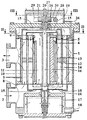
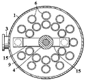
図1および2はフィルタ装置を示しており、これは例えばモータの運転時に継続的にオイルを濾過するジーゼルモータの潤滑油フィルタして用いることができる。装置はジャケット1、濾過すべき流れ用の入口チャネル2、濾過された流れ用の出口チャネル3、および装置の中間軸4の周りに2つの入れ子状リングとして配列された複数の細長いキャンドル形フィルタ要素5を備えている。フィルタ要素5の外被ジャケットは多孔性のフィルタ材料でできており、流れがフィルタ要素の内部からジャケットを通してフィルタ要素外に拡がる際に、流れ内の固体粒子やその他の不純物を確保する。濾過すべき流れをフィルタ要素5に導くために、各要素はその上端6および下端7で開放されている。フィルタ要素の下端および上端の両方において、隣り合う端部6および7の間の空間は水平プレート8,9で閉じられている。プレート8,9は更に、垂直な円筒状の壁10によって互いに結合されており、この円筒状壁10は濾過すべき流れのための流路11をその内部に形成している。このように、流れはジャケット1によって限定された空間へと拡散し、そこからフィルタ要素5の開放端6,7を通してフィルタ要素内に入り込み、フィルタ要素の外被ジャケットを通してフィルタ外に出て、そして浄化されて出口チャネル3へと排出されることができる。
【0016】
図1に示す装置において、各キャンドル形フィルタ要素5は水平固体隔壁12によって2つに区分けされている。即ち、各要素5はその上端で開放されている上側部13とその下端で開放されている下側部14とからなり、濾過すべき流れはそれらを通して互いに独立して流れる。
【0017】
濾過過程において、フィルタ要素5の外被ジャケットの内面に捕集された固体物質は次第に外被ジャケットの孔をふさぐようになり、濾過能力を低下させる。フィルタ要素の性能を維持するために、装置は逆洗を備えており、これは濾過すべき流れのフィルタ要素外被ジャケットを通しての流れとは反対方向、即ち外被ジャケットの外側から内側に向かう方向の濾過された流れの圧力を用いて行われる。隣接するフィルタ要素5の上と下に、フィルタ要素の異なる端部6,7に代わる代わる接続される洗浄機関15が配設されており、洗浄流を発生するためにフィルタ要素を低い圧力に接続している。両洗浄機関とも2つの洗浄アーム15からなり、アームの各長さはフィルタ要素の形成する入れ子リングの各半径と等しい。洗浄アームは中空チューブから作られ、同じく中空の装置の中空中間軸4に固定され、これらが協同してフィルタ要素を洗浄する洗浄流の排出チャネル16として働く。排出チャネル16は装置の下部へと向かい、そこから洗浄流は適宜、例えばフィルタ17を通った後に大気圧力にある排出アセンブリ18へと、排出される。
【0018】
以上に説明した装置において、逆洗は軸4とそれに固定された洗浄アーム15とが反時計周りの回転運動をするように行われ、洗浄アームはその端部を異なるフィルタ要素5の端部6,7に代わる代わる接続して行き、その結果これらフィルタ要素の内部空間を、排出チャネル16および排出アセンブリ18内の圧力(これは濾過された流れの圧力よりも低い)に接続し、それによって逆洗を発生させる。フィルタ要素5の一端と隔壁12との間の部分における洗浄は、該要素の他端が開放されている時と同時に行われるので、濾過はこの要素の上記開放された端の側で継続して行われうる。たとえば、図1に示す状態では、濾過は最も左側のフィルタ要素の下側部分14で継続しており、他方で上側部分13では逆洗が行われている。また最も右側のフィルタ要素の上側部分13では濾過が継続しており、同時に該要素の下側部分では逆洗が行われている。更に当然ながら、洗浄アーム15に接続されていないフィルタ要素においては濾過はとぎれずに行われている。この過程において、各フィルタ要素の下側部分および上側部分は一定の間隔で逆洗によって洗浄され、装置全体の濾過能力は過程を通じてほぼ一定に保たれる。
【0019】
装置の軸4と該軸に堅固に固定された洗浄アーム15からなる構造の回転運動は、図3および4にその構造と動作を示す機構によって生み出される。この回転機構は装置のジャケット1が画成する濾過空間上方のケーシング19内に設置されており、装置の軸4の端部20がこのケーシング内に延在している。軸20は、軸を環状に取り巻き図3および4に示すように往復運動する機関21を有するフリーホイールクラッチによって駆動される。その際、機関21は軸と交互に滑動接触状態およびロックされた状態となり、その運動方向に応じて上記機関と共に軸を回動させる。傾斜式の柔軟なはめ歯(inclined flexible or yielding cogging)などを利用することができるこのような結合方式はそれ自体公知である。機関21はこのように図3の位置から図4の位置へと軸20上を滑動し、その際軸20は静止しているが、機関が図3の位置に復帰する際に機関は軸にロックされ、軸を反時計周りに1ステップ分回転させる。このように、軸20は反時計周りに進み、洗浄アームが異なるフィルタ要素5を代わる代わる洗浄段階へと接続するべく洗浄アーム15(図1および図2)を回転させる。
【0020】
軸20を取り巻く環状の機関21は、互いに対向する2つの突出アームを備えており、その一方のアーム22はシリンダ24内を移動するピストン25に関節式に接続されている。装置の濾過室における濾過された流れの高い圧力と洗浄チャネル16における低い圧力とを利用して、これらの圧力をピストン25の異なる側に交互に接続することにより、ピストン25はシリンダ24内で前後に運動する。濾過された流れの側からは、濾過室がチャネル26を介してフリーホイールクラッチを内蔵するケーシング19と接続されており、ケーシングは潤滑油等の濾過された物質で満たされる。また、チャネル27を介してケーシング19から洗浄チャネル16への接続が確立される。ピストン25はメインバルブ28とそれを制御する2つの制御バルブによって制御される。メインバルブ28は、チューブ31,32を用いて、フライホイールクラッチを駆動するピストン25の異なる側においてシリンダ24に接続されている。図において、左側の制御バルブ29はチューブ33によってメインバルブ28の前端に接続されており、右側の制御バルブ30はチューブ34によってメインバルブの後端に接続されている。更にメインバルブ28および制御バルブ29,30はチューブ35,36,37,38によって上記圧力の低いチャンネル27に接続されている。
【0021】
図3に示すフリーホイールクラッチ位置において、アクチュエータ21のアーム23はスプリングに抗してピストン39を左側制御バルブ29の内部の位置に押し込んでおり、その位置で制御バルブ29はケーシング19内の高い圧力をアセンブリ40からチューブ33へと、そしてそこからメインバルブ28の先端へと解放し、そこでメインバルブのピストンをケーシング19の圧力をアセンブリ42からチューブ31へと解放する位置まで押しており、これによってこの圧力がフリーホイールクラッチを駆動するピストン25の右側においてシリンダ24に接続される。同時に、メインバルブ28の後端はチューブ34、右側制御バルブ、およびチューブ38を介してチャネル27の低い圧力に接続されている。メインバルブ28のピストン41の運動は、チューブ32,メインバルブ、およびチューブ35を介してシリンダ24をピストン25の左側において上記低い圧力に接続する。
【0022】
ケーシング19内の圧力をチューブ31を介してピストン25の右側においてシリンダ24に接続したことにより、ピストン25は図の左方向に動き、このピストンと軸20を駆動する機関21は図4に示す位置へと滑動する。この場合、アクチュエータアーム23は右側制御バルブ30(その構造は左側制御バルブ29と鏡像関係にある)をスプリングに抗してその内側ピストン位置まで押し込み、その位置で制御バルブ30はケーシング19内の圧力をチューブ34を介してメインバルブ28の後端へと解放し、そこで圧力はピストン41を押し、それによって今度はチューブ32がアセンブリ42を介してケーシング19の高い圧力に接続され、かつチューブ31はメインバルブ28およびチューブ36を介してチャネル27内の低い圧力に接続される。同時に、アーム23が移動したことにより左側制御バルブ29のピストン39はスプリングに押されて右方向に移動しており、その結果メインバルブの先端はチューブ33、左側制御バルブ29、およびチューブ37を介してチャネル27内部の低い圧力に接続されているので、メインバルブ28のピストン41の移動が可能となっている。
【0023】
図4に示す配置においてケーシング19内の高い圧力をシリンダ24の左側に接続したことにより、ピストン25およびそれと共にアクチュエータ21とそれにロックされた軸20までもが反時計周りに図3の位置へと戻って行き、同時に右側制御バルブ30のピストン43の移動により、メインバルブ28の後端がチャネル27内の低い圧力に接続され、メインバルブのピストン41の移動が可能となる。アクチュエータアーム23は左側制御バルブ29のピストン39を、ケーシング19の圧力をメインバルブ28の前端につながるチューブ33に接続するような位置にへと押す。こうして回転機構はその初期位置まで復帰し、その後以上に述べたような仕方で動作が続いて行く。
【0024】
洗浄期間(washing period)の持続時間は、洗浄アーム15を洗浄すべきフィルタ要素の位置で所望の時間停止することにより調整できる。この調整は、一例として、チューブ31および32内に設けた流れ制御バルブ(不図示)によって行うことができる。この流れ制御バルブはシリンダ24のピストン25の逆方向ストロークを遅延させるものであり、それによりアーム15は懸案の動作の間、静止を維持する。アーム15の回転運動を調節する別の方法として、チャネル26に配置した1つまたは複数のバルブを用いてチャネル26および27経由でシリンダ24に出入りする流れを制限することによるケーシング内の圧力調整を利用してもよい。
【0025】
図5〜7はフィルタ装置の軸20および洗浄アームを回転するフリーホイールクラッチの別の制御機構を示す。図5〜7に示す構造において、往復運動する結合リング21と,ピストンシリンダ24と,バルブ28と,バルブとピストンシリンダとの間のチューブ31,32と,洗浄チャネルに通ずる流れアセンブリ27と、バルブ28から流れアセンブリ27に通ずるチューブ35,36と、については図3および図4に関連して示した上記のものに対応するので、ここでは詳しくは説明しない。
【0026】
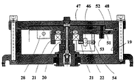
図3および図4に示すものと比較して、図5〜7の実質的な相違は、図3,4のメインバルブ28に相当するバルブ28がシステムの唯一の制御バルブを構成する点である。図5〜7においては、図3および図4の制御バルブ39,40がフリーホイールクラッチの回転部分の一部である2つの突出アーム44,45に置き換えられており、これらアームが往復回転運動と共にバルブ28を2つの位置の間で前後に移動させて、洗浄チャネルおよび流れアセンブリ27における高い圧力とバルブ28を包含するフリーホイールクラッチのケーシング19における低い圧力とをシリンダ24のピストンの異なる側に交互に導いて、リング21の往復運動および軸20のパラレルな(即ち同方向の)ステップ式回転運動を維持する。図5はアーム44がバルブ28のピストンを最も右側のピストン位置に押し込んだときにおける、リング21および左側アーム44の位置を示している。図6では、シリンダ24のピストンがアーム22を押すことにより、リング21をその運動(移動)行程の中間位置まで反時計周りに回転させており、そこにおいてバルブ28を駆動するアーム44,45はバルブの両方の端部から離れている。回転運動が更に続くにつれ、右側アーム45がバルブ28のピストンを最も左側の位置まで押し、シリンダ24のピストンの異なる側の圧力が位置を交代し、ピストンの逆方向ストロークおよびリング21の時計回り回転が始まり、図5の位置へと戻る。
【0027】
圧力差によって制御されるフリーホイールクラッチには、圧力差が小さい場合、および/または、機構の可動部分に摩擦がある場合に、シリンダ24が動き始めても最後まで移動する力が不十分で軸20を回転させずに止まってしまう、という事態が容易に起こるという問題がある。また、アーム44,45の力がバルブ28のピストンを動かすのに十分でない場合があり、これは装置の継続的動作を条件づけている。これらの問題は次に説明する磁石を用いた構造によって解決されている。
【0028】
ピストンシリンダ24のアーム22により回転させられ、軸20周りに枢動するクラッチリング21の他にも、このカプリング(coupling)はそれ自身のクランクアーム46を備えた別個の結合リング47を有しており、これもまた枢動して軸20を回転させる。バルブ28のピストンを動かすアーム44,45はこの後者のリング47に取り付けられている。アーム46と結合リング47の回転はアーム内のおよびケーシングに対して静止して配設された磁石を援用して行なわれる。アームの端部46には磁石48が配設されており、これが図5および図6に示す、行程路の両端に静止して取り付けられた磁石49,50に引きつけられる。アーム46はわずかに結合リングの方向において第2の磁石51を有しており、2つの反発磁石52,53がその上下に配置されている。直前に述べた3つの磁石51,52,53は、アーム46が図46に示すような中間位置にあるときに、互いに向き合うように位置する。
【0029】
図5に示す結合リングの回転初期位置において、引きあう磁石48および49は回転を減速する効果を及ぼす。図5の初期位置からリング21が中途まで回転した状態である図6の位置へ移行する際に、磁石48と49との引力はそれらの距離が増すにつれて小さくなり、同時に磁石51−53の反発力はそれらが互いに近づくにつれて大きくなる。このように、磁石による付加的な効果はリング21の回転に抵抗する。
【0030】
しかしながら、回転機構のこの作動概念では、回転運動がシリンダ24のピストンによって行われるのは、図5の初期位置から図6の中間移動位置へのアーム22および26の移動(運動)に限られるということである。このときアーム22および46とリング21および47とは共に回転する。移動の中間位置において、磁石の効果は不安定であり、移動中間位置を過ぎるとすぐに互いに反発する磁石51−53がアーム46の運動に強い推進力を与え、更に互いに近づいて来る引き合う磁石48および50により運動は更に推進される。因みに、このときまでにシリンダ24のピストンに押されたアーム22と共に移動してきているアーム46は、図5,6に示す制御ねじで調節される公差の範囲内でピストンに押されるアーム22の面前で移動することができ、かつ結合リング47の回転により回転運動を完了することができる。このように、中間位置以降の回転運動はピストンシリンダ内にある圧力差にもはや依存せず、かつ磁石によって終端に向けて加速される回転運動は、単に圧力差とシリンダピストンによって動作する場合に起こりうるように未完のまま終わってしまうということになりにくい。
【0031】
図5〜7に示す上述のフリーホールクラッチの作動機構は、発明性があると出願人は考えており、またフィルタ装置の洗浄機関軸の回転以外にも、ステップ式回転移動が圧力差で制御されるような他の応用例に適用できる。
【0032】
本発明の様々な実施形態は上記の例に示すものに限らず、添付の請求の範囲の範囲内で様々に変形し得ることは当業者には明らかである。特に本発明の装置のフィルタ要素(これは本発明の主要な対象ではない)の構成および細かな構造は、図示のものとは異なるものとしてもよい。また本発明において、洗浄機関をフィルタ要素の両端に配置することは必要ではなく、一つの洗浄機関をフィルタ要素の一端に設け、各フィルタ要素が順番に該洗浄機関に接続されるようにすれば十分である。
【0033】
図5−7に示した機構において、引きつけ磁石48−50または反発磁石51−53のどちらか一方だけでも、十分に必要な回転運動を強化する効果が得られる。
【図面の簡単な説明】
【図1】 本発明のフィルタ装置の垂直断面図である。
【図2】 図1のII−IIに沿った水平断面図であり、装置の並列フィルタ要素およびその上の洗浄機関を示している。
【図3】 図1のIII−IIIに沿った断面図であり、装置の軸を回転させるためのフリーホイールクラッチとそれに接続された制御バルブとを、カプリング動作の一番端の位置において示す図である。
【図4】 図3と同様の図であり、フリーホイールクラッチを別の一番端の位置において示している。
【図5】 本発明の第2実施形態のフリーホイールクラッチをそれに関連する制御バルブと共に示す図であり、カプリング動作は別の一番端の位置にある。
【図6】 図5におけるフリーホイールクラッチを動作の両端の中間位置において示す図である。
【図7】 図5および図6のカプリング装置の垂直断面図である。[0001]
The present invention relates to a filter device (filter device), which filter device has an inlet channel for the flow to be filtered, an outlet channel for the filtered flow, a plurality of parallel filter elements, and at least one rotation. The plurality of parallel filter elements can be introduced with a flow to be filtered so that permeation from the filter elements can occur through the jacket of the filter elements, An alternative connection to the element forms an outlet channel for backflushing the filter element caused by the pressure of the filtered flow. The invention further relates to a method for cleaning the filter element of the apparatus.
[0002]
The filter device as described above is particularly necessary as a fuel or lubricating oil filter in the motor, and the motor can be continuously operated for a long time by continuing the backwashing. A typical device has a number of filter elements, the main part of which continues to operate while one or several elements are being cleaned at a time, depending on the number of cleaning arms.
[0003]
A conventional backwashable filter device is described in German Patent Publication DE-4 340 275. The device has parallel candle-shaped filter elements arranged as two nested rings around a vertical axis. The flow to be filtered is directed from the upper end to the lower end of the filter element, and permeation from the filter element occurs through the cylindrical jacket jacket of each filter element. For the backwashing of the filter element, a washing engine consisting of two washing arms of different lengths is arranged below the filter element and these arms are fixed on the rotatable vertical shaft of the device. The cleaning arms are connected instead of the lower ends of the different filter elements to form an outlet channel for the cleaning flow. Corresponding to the cleaning arm, a closer is attached to the device rotation shaft above the filter element. The closer closes the upper end of the filter element in question during the washing phase and prevents the stream to be filtered from mixing with the washing stream.
[0004]
According to DE-4 340 275, the rotational movement of the vertical axis of the device and the cleaning arm is caused by the turbine rotor provided in the inlet channel of the flow to be filtered and the cogwheel connected to it and acting as a transmission mechanism. Brought by the help of. That is, the movement of the cleaning arm is maintained by the kinetic energy of the flow entering the device.
[0005]
The disadvantage of the solution described in DE-4 340 275 is that the rotation of the cleaning arm depends on the flow rate of the flow to be filtered (which can vary) entering the device. If the flow rate is too fast, the cleaning arm will rotate too fast and the cleaning period of the filter element will be too short. And if the flow rate is too slow, it will stop at all if the wash arm rotates too slowly from one filter element to another, or if the flow becomes too slow to turn the turbine motor. . Further, the rotation of the cleaning arm is hindered by contamination of the rotor and the transmission mechanism, and the mechanism is difficult to maintain due to the structure of the apparatus.
[0006]
The object of the present invention is to eliminate the disadvantages of the prior art by providing a solution such as rotating the shaft of the device and one or several cleaning engines using the fluid pressure present in the device. is there. A feature of the filter device of the present invention is that a freewheel clutch is connected to the rotating shaft of the cleaning engine, which cleans the reciprocating motion created by the pressure of the flow present in the device and the alternating lower pressure. It is to convert the engine into a stepped rotary motion in the same direction continuously.
[0007]
According to the invention, the rotation of the cleaning engine and the cleaning period of the different filter elements are produced by a pressure range, which can be kept substantially constant or smaller than the flow velocity of the flow flowing into the device. It is also possible to change. This ensures that a sufficiently long cleaning period is repeated at an appropriate frequency in all filter elements of the device.
[0008]
A substantial advantage of the second solution of the present invention is that the freewheel clutch may be located outside the filtration chamber of the device and connected to the rotating shaft, thereby allowing the freewheel clutch and other rotations. It is easy to maintain the engine that maintains the pressure, and it can also be performed while the filtration continues.
[0009]
The free wheel clutch can be constituted by an actuator that drives the rotating shaft of the cleaning engine, and the shaft rotates together with the engine by being alternately brought into a sliding contact state and a locked state with respect to the shaft. This movement of the actuator can be generated, for example, by articulating the actuator with a reciprocating piston based on alternating pressures.
[0010]
By configuring the filtered flow to act on the piston or other washing engine that drives the freewheel clutch, the pressure of the filtered flow is particularly advantageously used to rotate the washing engine. . Since the filtered stream is clean, it does not substantially contaminate the rotating mechanism more than the unfiltered stream. The apparatus of the present invention preferably has channels and associated valves for alternately connecting the filtered flow pressure and the lower counter pressure to the different sides of the piston.
[0011]
The lower pressure against the filtered flow may be the pressure in the apparatus wash flow outlet channel, to which a piston or other actuator may be connected. In motor filters, the outlet channel is generally at ambient atmospheric pressure.
[0012]
The solution according to the invention makes it possible to adjust the rotational movement of the cleaning engine in a hydraulic manner, so that the frequency and duration of the cleaning period can be controlled. In this way, the movement of the cleaning engine is attenuated or stopped exactly at the position of the element to be cleaned and the cleaning engine remains there for the desired time until the movement continues.
[0013]
In the method of the present invention, an inlet channel for the flow to be filtered, an outlet channel for the filtered flow, and several parallel filter elements into which the flow to be filtered is introduced so that the jacket of the filter element The filter element is cleaned in a filter device comprising a filter element that penetrates out of the filter element. This cleaning is performed as a backwash directed to the cleaning engine by the pressure of the filtered stream by connecting different filter elements to an alternative cleaning engine. The essential point in this method is that the rotation axis of the cleaning engine is always rotated stepwise in the same direction by using a mechanism, and the reciprocating motion of the mechanism alternately changes the pressure of the flow in the apparatus. Produced by lower pressure to take turns. Preferably the former pressure is the filtered clean stream pressure in the apparatus, the lower pressure being the ambient environmental pressure in the scrub arm.
[0014]
In this method, the stepping of the cleaning engine can be performed by a free wheel clutch having an engine that drives the rotating shaft of the cleaning engine, and the driving engine is alternately in a sliding contact state and a locked state with respect to the rotating shaft. The shaft is rotated, and the engine is moved by a piston articulated to the engine, and the piston is reciprocated by alternate connection of the different pressures on the different sides. Is.
[0015]
Next, the present invention will be described in more detail with reference to examples and the accompanying drawings.
FIGS. 1 and 2 show a filter device, which can be used as a lubricating oil filter for a diesel motor that continuously filters oil during motor operation, for example. The device comprises a
[0016]
In the apparatus shown in FIG. 1, each candle-shaped
[0017]
During the filtration process, the solid material collected on the inner surface of the jacket of the
[0018]
In the apparatus described above, the backwashing is carried out so that the
[0019]
The rotational movement of the structure consisting of the
[0020]
An
[0021]
In the free wheel clutch position shown in FIG. 3, the
[0022]
By connecting the pressure in the
[0023]
In the arrangement shown in FIG. 4, the high pressure in the
[0024]
The duration of the washing period can be adjusted by stopping the
[0025]
5-7 show another control mechanism for the freewheel clutch that rotates the
[0026]
Compared with those shown in FIGS. 3 and 4, the substantial difference between FIGS. 5-7 is that the
[0027]
The free wheel clutch controlled by the pressure difference has a
[0028]
In addition to the
[0029]
In the initial rotation position of the coupling ring shown in FIG. 5, the attracting
[0030]
However, in this operating concept of the rotation mechanism, the rotation movement is performed by the piston of the
[0031]
The above-described free hole clutch operating mechanism shown in FIGS. 5 to 7 is considered by the applicant to be inventive, and in addition to the rotation of the cleaning engine shaft of the filter device, the step type rotational movement is controlled by the pressure difference. It can be applied to other application examples.
[0032]
It will be apparent to those skilled in the art that various embodiments of the present invention are not limited to those shown in the above examples, and that various modifications can be made within the scope of the appended claims. In particular, the configuration and fine structure of the filter element (which is not the main subject of the present invention) of the device of the present invention may be different from that shown. In the present invention, it is not necessary to dispose the cleaning engine at both ends of the filter element. If one cleaning engine is provided at one end of the filter element, each filter element is connected to the cleaning engine in turn. It is enough.
[0033]
In the mechanism shown in FIGS. 5-7, only one of the attracting magnets 48-50 and the repelling magnets 51-53 has an effect of sufficiently enhancing the necessary rotational motion.
[Brief description of the drawings]
FIG. 1 is a vertical sectional view of a filter device of the present invention.
FIG. 2 is a horizontal cross-sectional view along II-II in FIG. 1, showing the parallel filter element of the apparatus and the cleaning engine thereon.
3 is a cross-sectional view taken along the line III-III in FIG. 1, showing a freewheel clutch for rotating the shaft of the apparatus and a control valve connected thereto at the extreme end position of the coupling operation. It is.
FIG. 4 is a view similar to FIG. 3, showing the freewheel clutch in another extreme position.
FIG. 5 is a view showing a freewheel clutch according to a second embodiment of the present invention together with a control valve related thereto, and a coupling operation is at another extreme position.
6 is a view showing the freewheel clutch in FIG. 5 at intermediate positions at both ends of the operation. FIG.
7 is a vertical sectional view of the coupling device of FIGS. 5 and 6. FIG.
Claims (10)
Applications Claiming Priority (3)
| Application Number | Priority Date | Filing Date | Title |
|---|---|---|---|
| FI991997A FI107021B (en) | 1999-09-20 | 1999-09-20 | Filtration plant and method for flushing its filter elements |
| FI19991997 | 1999-09-20 | ||
| PCT/FI2000/000800 WO2001021280A1 (en) | 1999-09-20 | 2000-09-20 | Filtering apparatus and method for washing of its filtering elements |
Publications (2)
| Publication Number | Publication Date |
|---|---|
| JP2003509203A JP2003509203A (en) | 2003-03-11 |
| JP4043786B2 true JP4043786B2 (en) | 2008-02-06 |
Family
ID=8555313
Family Applications (1)
| Application Number | Title | Priority Date | Filing Date |
|---|---|---|---|
| JP2001524701A Expired - Fee Related JP4043786B2 (en) | 1999-09-20 | 2000-09-20 | Filter device and method for cleaning the filter member |
Country Status (10)
| Country | Link |
|---|---|
| US (2) | US20020092814A1 (en) |
| EP (1) | EP1231998B1 (en) |
| JP (1) | JP4043786B2 (en) |
| KR (1) | KR100752788B1 (en) |
| DE (2) | DE60035893T2 (en) |
| DK (1) | DK1231998T3 (en) |
| ES (1) | ES2183751T3 (en) |
| FI (1) | FI107021B (en) |
| NO (1) | NO20021352L (en) |
| WO (1) | WO2001021280A1 (en) |
Families Citing this family (10)
| Publication number | Priority date | Publication date | Assignee | Title |
|---|---|---|---|---|
| DE10024401A1 (en) * | 2000-05-19 | 2001-11-22 | Boll & Kirch Filter | Reversible flow filter for lubricant oil; has open filter elements at each end of filter casing around rotating shaft and cleaning unit moved by shaft to clean filter elements during reverse flow |
| DE102004004756A1 (en) | 2004-01-30 | 2005-08-25 | Hydac Process Technology Gmbh | filter means |
| WO2006050706A2 (en) * | 2004-11-12 | 2006-05-18 | Tiefenbach Control Systems Gmbh | Flushable filter column for a liquid, comprising several filter units |
| KR100630372B1 (en) | 2005-02-04 | 2006-09-29 | 주식회사 에네트 | Filtering Device |
| US7487875B2 (en) * | 2005-08-30 | 2009-02-10 | General Electric Company | Candle filter assembly and candle filter element |
| FI121367B (en) * | 2008-07-29 | 2010-10-29 | Parker Hannifin Oy | Rotary device and filtration method applying it |
| CN101658741B (en) * | 2009-09-28 | 2011-05-04 | 郑业 | Reflow backwashing mechanism for automatic filtration of fluid |
| KR101287090B1 (en) * | 2011-10-13 | 2013-07-17 | 주식회사 파나시아 | A High- efficiency Candle type Apparatus for Filtering Ballast Water with High-density Filters |
| KR101287114B1 (en) * | 2011-10-14 | 2013-07-17 | 주식회사 파나시아 | A Candle type Apparatus for Filtering Ballast Water Preventing Backpressure |
| CN115804983B (en) * | 2022-12-23 | 2023-09-08 | 珂睿斯科技(深圳)有限公司 | Self-cleaning continuous water purification filter element and self-cleaning method |
Family Cites Families (10)
| Publication number | Priority date | Publication date | Assignee | Title |
|---|---|---|---|---|
| US3176846A (en) * | 1961-10-17 | 1965-04-06 | Renard P Adams | Automatic strainer |
| US3169109A (en) * | 1962-04-16 | 1965-02-09 | Hirs Gene | Filter apparatus |
| US3176946A (en) | 1963-12-11 | 1965-04-06 | Floyd M Burdick | Watch holder |
| FR1437838A (en) * | 1965-06-11 | 1966-05-06 | Filter with automatic cleaning device for all fluids | |
| US3476248A (en) * | 1968-03-01 | 1969-11-04 | Renard P Adams | Suction backwash means for a low pressure,multiple element,filter assembly |
| US4482461A (en) * | 1982-12-20 | 1984-11-13 | French Systems, Inc. | Backwash control for constant volume-pressure filtration system |
| DE4030084C2 (en) * | 1990-09-22 | 1999-09-30 | Boll & Kirch Filter | Backwash filter |
| DE4345412C2 (en) * | 1993-11-26 | 1999-11-11 | Boll & Kirch Filter | Filter candle |
| DE4340275C2 (en) * | 1993-11-26 | 1999-10-21 | Boll & Kirch Filter | Backwash filter |
| FI110483B (en) * | 1999-09-20 | 2003-02-14 | Parker Hannifin Oy | filtration plant |
-
1999
- 1999-09-20 FI FI991997A patent/FI107021B/en not_active IP Right Cessation
-
2000
- 2000-09-20 ES ES00960728T patent/ES2183751T3/en not_active Expired - Lifetime
- 2000-09-20 KR KR1020027002804A patent/KR100752788B1/en not_active IP Right Cessation
- 2000-09-20 DK DK00960728T patent/DK1231998T3/en active
- 2000-09-20 DE DE60035893T patent/DE60035893T2/en not_active Expired - Lifetime
- 2000-09-20 WO PCT/FI2000/000800 patent/WO2001021280A1/en active IP Right Grant
- 2000-09-20 JP JP2001524701A patent/JP4043786B2/en not_active Expired - Fee Related
- 2000-09-20 DE DE1231998T patent/DE1231998T1/en active Pending
- 2000-09-20 EP EP00960728A patent/EP1231998B1/en not_active Expired - Lifetime
-
2002
- 2002-03-04 US US10/090,512 patent/US20020092814A1/en not_active Abandoned
- 2002-03-19 NO NO20021352A patent/NO20021352L/en unknown
-
2003
- 2003-09-11 US US10/660,392 patent/US6827864B2/en not_active Expired - Lifetime
Also Published As
| Publication number | Publication date |
|---|---|
| EP1231998B1 (en) | 2007-08-08 |
| EP1231998A1 (en) | 2002-08-21 |
| ES2183751T1 (en) | 2003-04-01 |
| ES2183751T3 (en) | 2008-02-16 |
| US20020092814A1 (en) | 2002-07-18 |
| US20040050803A1 (en) | 2004-03-18 |
| NO20021352D0 (en) | 2002-03-19 |
| DE60035893D1 (en) | 2007-09-20 |
| US6827864B2 (en) | 2004-12-07 |
| NO20021352L (en) | 2002-03-19 |
| DE1231998T1 (en) | 2003-02-06 |
| KR20020029939A (en) | 2002-04-20 |
| WO2001021280A1 (en) | 2001-03-29 |
| KR100752788B1 (en) | 2007-08-29 |
| FI107021B (en) | 2001-05-31 |
| FI19991997A (en) | 2001-03-20 |
| JP2003509203A (en) | 2003-03-11 |
| DK1231998T3 (en) | 2007-11-19 |
| DE60035893T2 (en) | 2008-04-17 |
Similar Documents
| Publication | Publication Date | Title |
|---|---|---|
| JP3946519B2 (en) | Filtration device | |
| JP4043786B2 (en) | Filter device and method for cleaning the filter member | |
| FI92800B (en) | Self-cleaning filter | |
| US20090050582A1 (en) | Self-Cleaning System For Filter | |
| US9061226B2 (en) | Filtration method with self-cleaning filter assembly | |
| US3445002A (en) | Filter unit with automatic cleaning and automatic discharge of collected impurities | |
| US20120228239A1 (en) | Filter device operating method | |
| CN111790198B (en) | System, wiping element and method for cleaning a membrane element, in particular of a water-conducting household appliance | |
| EP3600599A1 (en) | Water filter | |
| CN116075349A (en) | Filter device | |
| CN115784401B (en) | Anti-blocking urban sewage treatment device | |
| CN117138491B (en) | Automatic change purification product intelligent management device | |
| CN220715008U (en) | Self-flushing type filter cylinder | |
| RU2115458C1 (en) | Self-cleaning filter | |
| CN116637451A (en) | Movable air sterilization and purification equipment in laboratory | |
| FI121367B (en) | Rotary device and filtration method applying it | |
| SU1423144A1 (en) | Installation for separating suspensions | |
| SU946599A1 (en) | Self-cleaning filter | |
| CN116116228A (en) | Ultrafiltration membrane wire cleaning device with prevent impurity deposition function | |
| IL161727A (en) | Filter and filter cleaning apparatus and related methods | |
| JPS6019009A (en) | Backwashing type filter apparatus | |
| JPH0757290B2 (en) | Filtration machine and filtration device |
Legal Events
| Date | Code | Title | Description |
|---|---|---|---|
| A621 | Written request for application examination |
Free format text: JAPANESE INTERMEDIATE CODE: A621 Effective date: 20050520 |
|
| A977 | Report on retrieval |
Free format text: JAPANESE INTERMEDIATE CODE: A971007 Effective date: 20070223 |
|
| A131 | Notification of reasons for refusal |
Free format text: JAPANESE INTERMEDIATE CODE: A131 Effective date: 20070314 |
|
| A601 | Written request for extension of time |
Free format text: JAPANESE INTERMEDIATE CODE: A601 Effective date: 20070330 |
|
| A602 | Written permission of extension of time |
Free format text: JAPANESE INTERMEDIATE CODE: A602 Effective date: 20070406 |
|
| A521 | Written amendment |
Free format text: JAPANESE INTERMEDIATE CODE: A523 Effective date: 20070914 |
|
| TRDD | Decision of grant or rejection written | ||
| A01 | Written decision to grant a patent or to grant a registration (utility model) |
Free format text: JAPANESE INTERMEDIATE CODE: A01 Effective date: 20071022 |
|
| A61 | First payment of annual fees (during grant procedure) |
Free format text: JAPANESE INTERMEDIATE CODE: A61 Effective date: 20071114 |
|
| R150 | Certificate of patent or registration of utility model |
Free format text: JAPANESE INTERMEDIATE CODE: R150 |
|
| FPAY | Renewal fee payment (event date is renewal date of database) |
Free format text: PAYMENT UNTIL: 20101122 Year of fee payment: 3 |
|
| FPAY | Renewal fee payment (event date is renewal date of database) |
Free format text: PAYMENT UNTIL: 20111122 Year of fee payment: 4 |
|
| FPAY | Renewal fee payment (event date is renewal date of database) |
Free format text: PAYMENT UNTIL: 20121122 Year of fee payment: 5 |
|
| LAPS | Cancellation because of no payment of annual fees |