JP4042788B2 - Game machine - Google Patents

Game machine Download PDF

Info

Publication number
JP4042788B2
JP4042788B2 JP2006083549A JP2006083549A JP4042788B2 JP 4042788 B2 JP4042788 B2 JP 4042788B2 JP 2006083549 A JP2006083549 A JP 2006083549A JP 2006083549 A JP2006083549 A JP 2006083549A JP 4042788 B2 JP4042788 B2 JP 4042788B2
Authority
JP
Japan
Prior art keywords
sealing
preliminary
screw
box
unit
Prior art date
Legal status (The legal status is an assumption and is not a legal conclusion. Google has not performed a legal analysis and makes no representation as to the accuracy of the status listed.)
Expired - Fee Related
Application number
JP2006083549A
Other languages
Japanese (ja)
Other versions
JP2006204942A (en
JP2006204942A5 (en
Inventor
誠 中村
Current Assignee (The listed assignees may be inaccurate. Google has not performed a legal analysis and makes no representation or warranty as to the accuracy of the list.)
Sanyo Bussan Co Ltd
Original Assignee
Sanyo Bussan Co Ltd
Priority date (The priority date is an assumption and is not a legal conclusion. Google has not performed a legal analysis and makes no representation as to the accuracy of the date listed.)
Filing date
Publication date
Application filed by Sanyo Bussan Co Ltd filed Critical Sanyo Bussan Co Ltd
Priority to JP2006083549A priority Critical patent/JP4042788B2/en
Publication of JP2006204942A publication Critical patent/JP2006204942A/en
Publication of JP2006204942A5 publication Critical patent/JP2006204942A5/ja
Application granted granted Critical
Publication of JP4042788B2 publication Critical patent/JP4042788B2/en
Anticipated expiration legal-status Critical
Expired - Fee Related legal-status Critical Current

Links

Images

Description

本発明はパチンコ機やスロットマシーン等の遊技機に関するものである。   The present invention relates to a gaming machine such as a pachinko machine or a slot machine.

近年、パチンコ機およびスロットマシーン等の遊技機は、遊技盤に設けられる入賞装置および表示装置等を制御して遊技の興趣を盛り上げるものが主流となっている。この入賞装置および表示装置の制御はIC,LSI等の多数の電子部品を配設したロジック制御回路基板またはマイクロコンピュータを有する制御回路基板等により行われる。これらの制御回路基板は、遊技盤の裏面に配設される入賞球集合カバーまたは機構板に取り付けられる遊技機用基板ボックス内に収納されて遊技機に付設されている。この遊技機用基板ボックスは制御回路基板を被包して収納するためのボックスベースとボックスカバーとを備えている。   In recent years, gaming machines such as pachinko machines and slot machines have become mainstream that control the prize-winning devices and display devices provided on the game board to increase the fun of the game. The winning device and the display device are controlled by a logic control circuit board provided with a large number of electronic components such as IC and LSI, or a control circuit board having a microcomputer. These control circuit boards are housed in a gaming machine board box attached to a winning ball collecting cover or a mechanism board disposed on the back of the gaming board and attached to the gaming machine. This gaming machine board box includes a box base and a box cover for enclosing and storing the control circuit board.

ところで、かかる遊技機用基板ボックス内に収納された制御回路基板から遊技内容に関する制御情報が記憶されたROMを取り外し交換して、遊技機の遊技内容を変更する不正行為が近年問題になっている。このような不正行為の防止対策として、遊技機用基板ボックス内からROMを取り外すことができないように遊技機用基板ボックスのボックスベースとボックスカバーとを封印ねじ等の特殊ねじを用いて接合(連結)し、遊技機用基板ボックスを封印する方法が用いられている。   By the way, in recent years, the illegal act of changing the game content of the gaming machine by removing and replacing the ROM storing the control information regarding the game content from the control circuit board housed in the board box for gaming machines has become a problem. . As a countermeasure against such illegal acts, the box base of the gaming machine board box and the box cover are joined (connected) using a special screw such as a sealing screw so that the ROM cannot be removed from the gaming machine board box. And a method of sealing a board box for gaming machines is used.

しかしながら、基板ボックス内の回路基板を適法に検査する場合、封印ねじ等が封印部材に係合され、抜き取り不可能な状態で保持されているので、基板ボックスを開封することができないという問題点があった。   However, when legally inspecting the circuit board in the board box, the sealing screw or the like is engaged with the sealing member and is held in a state where it cannot be removed, so that the board box cannot be opened. there were.

本発明は上述した問題点を解決するためになされたものであり、回路基板を確実に封印して、遊技内容を変更する不正行為を防止し、一方、検査などのために開封された基板ユニットを再度封印することができる遊技機を提供することを目的としている。   The present invention has been made in order to solve the above-described problems. The circuit board unit is securely sealed to prevent an illegal act of changing game contents, while being opened for inspection or the like. It is an object to provide a gaming machine that can be sealed again.

この目的を達成するために請求項1記載の遊技機は、回路基板と、ベース及びカバーを有して内部に回路基板が設けられた基板ユニットであって、前記ベース側に設けられる第1封印手段と、前記カバー側に設けられる第2封印手段と、その第1封印手段と第2封印手段とを連結する連結封印部材とを有し、その連結封印部材によって前記第1封印手段と第2封印手段とが連結されている場合に前記回路基板を取り出すときには基板ユニットを破壊するか或いは所定の部位を切断することを必要とする基板ユニットを備えており、前記第1封印手段は、前記連結封印部材が挿入される第1封印部が複数並設され、その複数の第1封印部の列と離間した位置で前記複数の第1封印部と並列に設けられる第1取付部と、その第1取付部と第1封印部とを連結する第1連結部とを備えると共に、前記第2封印手段は、前記連結封印部材が挿入される第2封印部が複数並設され、その複数の第2封印部の列と離間した位置で前記複数の第2封印部と並列に設けられる第2取付部と、その第2取付部と第2封印部とを連結する第2連結部と、を備え、前記第1連結部が前記所定の部位であり、前記連結封印部材は、所定の長さを有する胴部と、該胴部と比較して最大外径が大きく形成された頭部とを有し、前記第1封印手段と前記ベースとが前記第1取付部を介して一体または一体的に設けられてベース体を形成し、前記第2封印手段と前記カバーとが前記第2取付部を介して一体または一体的に設けられてカバー体を形成し、前記連結封印部材の予備用の部材である予備用連結封印部材と、前記ベース体またはカバー体の一方に配設され、前記予備用連結封印部材の頭部より内径の小さい挿入部を有して該挿入部に前記予備用連結封印部材の胴部が挿入されると共に、前記予備用連結封印部材をその頭部の上面および周囲が外部に露出した状態で保持する予備用部材保持部と、前記ベース体またはカバー体の他方に配設される予備用部材係止部とを備え、その予備用部材係止部は、前記第1封印部と前記第2封印部とが前記連結封印部材により連結されている状態において、前記予備用部材保持部の挿入部と対向する位置に設けられ、前記第1封印部と前記第2封印部とが前記連結封印部材により連結されていない状態では、前記予備用部材保持部から抜き取り可能であり、前記第1封印部と前記第2封印部とが前記連結封印部材により連結されている状態では前記予備用部材係止部により抜き取り方向への移動を規制され、前記予備用部材保持部からの抜き取りが防止されている。 In order to achieve this object, the gaming machine according to claim 1 is a board unit having a circuit board, a base and a cover and having a circuit board provided therein, the first sealing provided on the base side. Means, a second sealing means provided on the cover side, and a connecting sealing member for connecting the first sealing means and the second sealing means, and the first sealing means and the second sealing member by the connecting sealing member. When the circuit board is taken out when the sealing means is connected to the sealing means, the board unit is required to be destroyed or a predetermined part must be cut, and the first sealing means is connected to the connecting means. A plurality of first sealing portions into which sealing members are inserted are arranged side by side, a first attachment portion provided in parallel with the plurality of first sealing portions at a position spaced apart from the row of the plurality of first sealing portions, and the first 1 mounting part and 1st seal The second sealing means includes a plurality of second sealing portions into which the connecting sealing member is inserted, and is spaced apart from a row of the plurality of second sealing portions. A second attachment portion provided in parallel with the plurality of second seal portions at a position, and a second connection portion for connecting the second attachment portion and the second seal portion, wherein the first connection portion is the The connecting sealing member has a body portion having a predetermined length and a head portion having a maximum outer diameter larger than that of the body portion; the first sealing means; The base is integrally or integrally provided via the first mounting portion to form a base body, and the second sealing means and the cover are integrally or integrally provided via the second mounting portion. And forming a cover body, a preliminary connection sealing member that is a preliminary member of the connection sealing member, The insertion portion is disposed on one of the base body and the cover body and has an insertion portion whose inner diameter is smaller than the head of the preliminary connection sealing member, and the trunk portion of the preliminary connection sealing member is inserted into the insertion portion. A spare member holding portion for holding the spare connecting seal member in a state where the upper surface and the periphery of the head are exposed to the outside, and a spare member locking portion disposed on the other of the base body or the cover body And the preliminary member locking portion faces the insertion portion of the preliminary member holding portion in a state where the first sealing portion and the second sealing portion are connected by the connection sealing member. In the state where the first sealing portion and the second sealing portion are not connected by the connecting sealing member, the first sealing portion and the second sealing portion can be extracted from the preliminary member holding portion. 2 sealing parts on the connecting sealing member In a more connected state, movement in the extraction direction is restricted by the preliminary member locking portion, and extraction from the preliminary member holding portion is prevented.

請求項2記載の遊技機は、請求項1記載の遊技機において、前記予備用部材保持部の挿入部は、その内径が前記予備用連結封印部材の胴部より大きく形成された入り口部と、該入り口部より挿入方向側にその内径が入り口部の内径より小さく形成された細径部とを設けたものである。   The gaming machine according to claim 2 is the gaming machine according to claim 1, wherein the insertion portion of the preliminary member holding portion has an entrance portion formed so that an inner diameter thereof is larger than a trunk portion of the preliminary connection sealing member. A narrow-diameter portion whose inner diameter is smaller than the inner diameter of the entrance portion is provided on the insertion direction side from the entrance portion.

本発明の遊技機によれば、回路基板をベースまたはカバー内に収納し、ベースに設けられた第1封印手段とカバーに設けられた第2封印手段とを対向させつつ、ベースとカバーとを合致させることにより、回路基板が基板ユニットに被抱される。回路基板の被抱後、連結封印部材によって第1封印手段と第2封印手段とを連結すると、基板ユニット内に回路基板を確実に封印することができる。よって、遊技内容に関する制御情報が記憶されたROMを回路基板から取り外して交換し、遊技内容を変更する不正行為を抑制することができるという効果がある。   According to the gaming machine of the present invention, the circuit board is accommodated in the base or the cover, and the first sealing means provided on the base and the second sealing means provided on the cover are opposed to each other, and the base and the cover are placed. By matching, the circuit board is held by the board unit. After the circuit board is held, the circuit board can be securely sealed in the board unit by connecting the first sealing means and the second sealing means by the connecting sealing member. Therefore, there is an effect that the ROM storing the control information related to the game content can be removed from the circuit board and exchanged to suppress an illegal act of changing the game content.

また、基板ユニットが封印されると、予備用部材保持部により頭部の上面および周囲が外部に露出した状態で保持された予備用連結封印部材は、予備用部材係止部により確実に係止され、予備用部材保持部から抜け落ちることが防止される。よって、予備用連結封印部材の紛失を防止することができるという効果がある。 Further, when the substrate unit is sealed, and more top and surrounding the connecting sealing member for pre-held in a state of being exposed to the outside of the head to spare member holding portion securely engaged by the protection member locking portion It is stopped and it is prevented from falling off from the preliminary member holding portion. Therefore, there is an effect that it is possible to prevent the spare connecting seal member from being lost.

更に、基板ユニットが開封された場合には、その開封の痕跡を確実に残すことができるので、かかる不正行為を早期に発見することができるという効果がある。
なお、連結封印部材には、スクリュードライバ等のねじ回し工具を係合させる係合溝ではなく、連結封印部材をねじ込み方向に回転させる場合、ねじ回し工具と係合可能となり、逆に連結封印部材を反ねじ込み方向に回転させる場合には、ねじ回し工具を空回りさせる係合溝、いわゆるワンウェイ十字溝を凹設しても良い。
Furthermore, when the substrate unit is opened, the trace of the opening can be surely left, so that it is possible to detect such an illegal act at an early stage.
Note that the connecting sealing member is not an engaging groove for engaging a screwdriver such as a screwdriver, but when the connecting sealing member is rotated in the screwing direction, it can be engaged with the screwdriver, and conversely the connecting sealing member. In the case of rotating the screw in the anti-screwing direction, an engagement groove for soaking the screwdriver tool, a so-called one-way cross groove, may be provided.

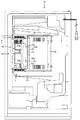
以下、本発明の好ましい実施例について、添付図面を参照して説明する。まず、図1及び図2を参照して、封印ユニット1が配設される基板ボックス40について説明する。図1は、本発明の遊技機用基板ボックス封印具の一実施例である封印ユニット1を有する基板ボックス40の配設されたパチンコ機50の裏面の部分断面図であり、図2は、図1のI−I線における平面部分断面図である。尚、図2に示す2点鎖線は、連接板45を介して基板ボックス40が回転された状態を図示している。   Hereinafter, preferred embodiments of the present invention will be described with reference to the accompanying drawings. First, with reference to FIG.1 and FIG.2, the board | substrate box 40 with which the sealing unit 1 is arrange | positioned is demonstrated. FIG. 1 is a partial cross-sectional view of the back surface of a pachinko machine 50 in which a board box 40 having a sealing unit 1 which is an embodiment of a board box sealing tool for gaming machines according to the present invention is disposed. It is a plane fragmentary sectional view in the II line of 1. 2 indicates a state in which the substrate box 40 is rotated via the connecting plate 45.

図1に示すように、基板ボックス40は、例えば、遊技機の一種であるパチンコ機50の遊技盤51の裏面に設けられた入賞球集合カバー52に取り付けられている。基板ボックス40は、パチンコ機50の遊技内容に関する制御情報を記憶した制御用ROM等の電子部品により構成された制御回路基板(図示せず)を被包するためのものであり、ボックス本体41と、そのボックス本体41に覆設されるボックス蓋体42とを備えている(図3参照)。この基板ボックス40の上下側の両側壁面には、封印ユニット1,1がそれぞれ取り付けられており、基板ボックス40内に制御回路基板を被包する場合には、かかる封印ユニット1,1の双方を用いて、基板ボックス40の上側および下側の2箇所を封印する。   As shown in FIG. 1, the board box 40 is attached to a winning ball collective cover 52 provided on the back surface of a game board 51 of a pachinko machine 50 that is a kind of game machine, for example. The board box 40 is for encapsulating a control circuit board (not shown) composed of electronic components such as a control ROM that stores control information related to the game contents of the pachinko machine 50. , And a box lid 42 covering the box body 41 (see FIG. 3). Sealing units 1 and 1 are respectively attached to the upper and lower side walls of the board box 40. When the control circuit board is encapsulated in the board box 40, both the sealing units 1 and 1 are attached. Used to seal the upper and lower portions of the substrate box 40.

図1および図2に示すように、基板ボックス40のボックス本体41には、連接板45が配設されている。連接板45は、正面視長板状に形成されたヒンジ部材であり、計4本の取付ピン45aを備えている。この各取付ピン45aのうち、2本の取付ピン45aは、連接板45の右側端部分に突設されており、その他の2本の取付ピン45aは、連接板45の左側端部分に突設されている。各取付ピン45aのうち、連接板45の右側端部分(図1中、右側)に突設されている各取付ピン45aは、ボックスベース41に設けられた各軸受板41dに回動可能にそれぞれ支持されている(図2参照)。また、連接板45の左側端部分(図1中、左側)に突設されている各取付ピン45aは、入賞球集合カバー52に突設された各軸受板52aに回動可能にそれぞれ差し込まれる。よって、基板ボックス40は、連接板45により入賞球集合カバー52に対して回動可能に配設される。そして、基板ボックス40は、入賞球集合カバー52に配設された留め具(図示せず)によって、連接板45による回動を防止するために係止される。   As shown in FIGS. 1 and 2, a connecting plate 45 is disposed on the box body 41 of the substrate box 40. The connecting plate 45 is a hinge member formed in a long plate shape when viewed from the front, and includes a total of four mounting pins 45a. Of these mounting pins 45a, two mounting pins 45a project from the right end portion of the connecting plate 45, and the other two mounting pins 45a project from the left end portion of the connecting plate 45. Has been. Of each mounting pin 45a, each mounting pin 45a protruding from the right end portion (right side in FIG. 1) of the connecting plate 45 is rotatable to each bearing plate 41d provided on the box base 41, respectively. It is supported (see FIG. 2). Further, each mounting pin 45a protruding from the left end portion (left side in FIG. 1) of the connecting plate 45 is rotatably inserted into each bearing plate 52a protruding from the winning ball collecting cover 52. . Therefore, the board box 40 is disposed so as to be rotatable with respect to the winning ball collecting cover 52 by the connecting plate 45. The board box 40 is locked by a fastener (not shown) disposed on the winning ball collecting cover 52 to prevent the connection plate 45 from rotating.

この基板ボックス40の状態を検査する場合には、留め具による基板ボックス40の係止を解除した後、図2に示すように、連接板45を介して基板ボックス40を反時計方向へ回転させて、図2中の2点鎖線の位置の方向へ移動させることにより、ボックス本体41の裏面を検査することができる。また、連接板45の入賞球集合カバー52の各軸受板52aに差し込まれた各取付ピン45aは、それぞれ各軸受板52aに対して着脱可能に形成されているので、基板ボックス40を入賞球集合カバー52から取り外して検査することもできる。   When inspecting the state of the substrate box 40, after the latch of the substrate box 40 by the fastener is released, the substrate box 40 is rotated counterclockwise via the connecting plate 45 as shown in FIG. Thus, the back surface of the box body 41 can be inspected by moving it in the direction of the two-dot chain line in FIG. In addition, each mounting pin 45a inserted into each bearing plate 52a of the winning ball assembly cover 52 of the connecting plate 45 is detachably attached to each bearing plate 52a. The cover 52 can be removed and inspected.

図3は、各封印ユニット1,1が配設された基板ボックス40が開封された状態を示す分解斜視図である。尚、図3では、基板ボックス40に配設された一方の封印ユニット1のみを図示している。   FIG. 3 is an exploded perspective view showing a state in which the substrate box 40 in which the sealing units 1 and 1 are disposed is opened. In FIG. 3, only one sealing unit 1 disposed in the substrate box 40 is illustrated.

図3に示すように、ボックス本体41は、金属材料から構成され中空状の箱状体に形成されており、その上方はボックス本体41内に制御回路基板を配設するために開放されている。また、ボックス本体41の側壁41aには封印ユニット1のユニット部材(第1封印具)20が取り付けられており、かかるユニット部材20の取付部材22はボックス本体41の一部として構成されている。更に、ボックス本体41の内側壁には薄板状のガイド板43が設けられており、ボックス本体41にボックス蓋体42を被せる場合、ボックス蓋体42の位置ズレを防止して、容易に被せることができる。   As shown in FIG. 3, the box main body 41 is made of a metal material and formed into a hollow box-like body, and the upper side thereof is opened to dispose the control circuit board in the box main body 41. . A unit member (first sealing tool) 20 of the sealing unit 1 is attached to the side wall 41 a of the box body 41, and the attachment member 22 of the unit member 20 is configured as a part of the box body 41. Further, a thin plate-shaped guide plate 43 is provided on the inner wall of the box body 41. When the box cover body 42 is covered with the box body 41, the box cover body 42 is prevented from being displaced and easily covered. Can do.

ボックス蓋体42は、ボックス本体41と同様に、金属製の中空箱状体に形成されており、その側壁42aには封印ユニット1のユニット部材(第2封印具)30が取り付けられており、かかるユニット部材30の取付部材32はボックス蓋体42の一部として構成されている。ボックス蓋体42の上部壁面には、透明な合成樹脂から構成された覗き窓42dが設けられており、基板ボックス40内の制御回路基板の様子や、その制御回路基板上に設けられた制御用ROMの型番号を容易に確認することができる。このため、制御回路基板を改造したり、制御用ROMを交換してパチンコ機50の遊技内容を変更する不正行為が行われた場合には、これを容易に発見することができる。   Similarly to the box body 41, the box lid body 42 is formed into a metal hollow box-like body, and a unit member (second sealing tool) 30 of the sealing unit 1 is attached to the side wall 42a. The attachment member 32 of the unit member 30 is configured as a part of the box lid body 42. A viewing window 42d made of a transparent synthetic resin is provided on the upper wall surface of the box lid 42, and the state of the control circuit board in the board box 40 and the control circuit provided on the control circuit board are provided. The ROM model number can be easily confirmed. For this reason, it is possible to easily find out if an unauthorized act of modifying the control circuit board or changing the game content of the pachinko machine 50 by exchanging the control ROM is performed.

また、ボックス蓋体42の上面には、基板ボックス40内に配設された制御回路基板を管理するための基板管理番号シール61が貼付される。図9には、かかる基板管理番号シール61の平面図が図示されている。   A board management number seal 61 for managing the control circuit board disposed in the board box 40 is affixed to the upper surface of the box lid 42. FIG. 9 is a plan view of the board management number seal 61.

図9に示すように、未使用の基板管理番号シール61は、台紙62に計4枚貼付されている。この基板管理番号シール61をボックス蓋体42に貼付する場合には、台紙62から1枚ずつ剥がして貼り付ければ良い。この基板番号管理シール61は、特殊シールで構成されており、その表面には、基板管理番号61aと、製造業者コード61bと、枠部61cと、検査履歴61dとが表示されている。基板管理番号61aとは、基板ボックス40に被包される制御回路基板のシリアル番号である。また、制御回路基板の製造業者は、枠部61cの色彩と製造業者コード61bとにより特定される。更に、この基板管理番号シール61は、制御回路基板の検査履歴書でもあり、検査履歴61dには、検査毎に「1」から「3」の欄に検査年月日(開封年月日)、検査者名(開封者名)および検査印等が記録される。   As shown in FIG. 9, a total of four unused board management number seals 61 are affixed to the mount 62. When affixing the substrate management number seal 61 to the box lid 42, the substrate management number seal 61 may be peeled off from the mount 62 one by one. The board number management sticker 61 is formed of a special sticker, and a board management number 61a, a manufacturer code 61b, a frame part 61c, and an inspection history 61d are displayed on the surface thereof. The board management number 61 a is a serial number of the control circuit board encapsulated in the board box 40. The manufacturer of the control circuit board is specified by the color of the frame portion 61c and the manufacturer code 61b. Further, the board management number seal 61 is also an inspection history of the control circuit board, and the inspection history 61d includes an inspection date (opening date) in the columns “1” to “3” for each inspection, An inspector name (opener name), an inspection seal, etc. are recorded.

尚、基板管理番号シール61を構成する特殊シールは、剥がされると破損してしまう性質を有するものであるので、基板管理番号シール61が不正に剥がされた場合には、かかる不正行為を容易に発見することができる。   The special seal constituting the board management number seal 61 has a property of being damaged when peeled off. Therefore, when the board management number seal 61 is illegally peeled off, the illegal act is easily performed. Can be found.

次に、図4から図8を参照して、封印ユニット1を構成する各部材について説明する。図4は、封印ユニット1を構成する各部材の分解斜視図であり、図5は、封印ユニット1のユニット部材20の下面図であり、図6は、基板ボックス40を封印した状態における封印ユニット1の部分断面図であり、図7は、予備用封印ねじ111を保持した状態を示した封印ユニット1の部分断面図であり、図8は、基板ボックス40の分解斜視図である。   Next, each member which comprises the sealing unit 1 is demonstrated with reference to FIGS. 4 is an exploded perspective view of each member constituting the sealing unit 1, FIG. 5 is a bottom view of the unit member 20 of the sealing unit 1, and FIG. 6 is a sealing unit in a state where the substrate box 40 is sealed. FIG. 7 is a partial sectional view of the sealing unit 1 showing a state in which the preliminary sealing screw 111 is held, and FIG. 8 is an exploded perspective view of the substrate box 40.

まず、図4に示すように、封印ユニット1は、基板ボックス40を封印するための封印ねじ11と、その封印ねじ11が螺入されるナット(保持部材)12と、封印ねじ11を係止するためのストッパ部材(抜け止め手段)13と、ナット12およびストッパ部材13が配設されるとともにボックス本体41の一部として取り付けられるユニット部材20と、そのユニット部材20に対向してボックス蓋体42の一部として取り付けられるユニット部材30と、封印ねじ11の予備用の部材である予備用封印ねじ111とを備えている。   First, as shown in FIG. 4, the sealing unit 1 locks the sealing screw 11 for sealing the substrate box 40, the nut (holding member) 12 into which the sealing screw 11 is screwed, and the sealing screw 11. Stopper member (prevention means) 13 for carrying out, unit member 20 on which nut 12 and stopper member 13 are arranged and attached as a part of box body 41, and box cover body facing the unit member 20 42, a unit member 30 attached as a part of 42, and a preliminary sealing screw 111 which is a preliminary member of the sealing screw 11.

封印ねじ11は、後述するユニット部材20,30における各封印部材21,31を連結するためのものであり、ステンレス鋼材等の金属材料から構成されている。この封印ねじ11は、封印部材21に挿入される軸部11aと、その軸部11aの一端に一体形成されるとともに後述する封印部材31に係合される頭部(係合部)11bとを備えている。   The sealing screw 11 is for connecting the sealing members 21 and 31 in the unit members 20 and 30 described later, and is made of a metal material such as a stainless steel material. The sealing screw 11 includes a shaft portion 11a inserted into the sealing member 21 and a head portion (engaging portion) 11b that is integrally formed at one end of the shaft portion 11a and that is engaged with a sealing member 31 described later. I have.

図4に示すように、封印ねじ11の軸部11aは、先端部11cと、おねじが螺刻されたおねじ部11dと、おねじが螺刻されていない非おねじ部11eとを備えている。先端部11cは、軸部11aの下端部に形成されており、その先端部分に形成されたテーパ部T1と、後述するストッパ部材13により係止される係止溝(係止部)11fとを有している。図6に示すように、封印ねじ11の先端部11cは、テーパ部T1を介して後述するストッパ部材13の内孔13bへ容易に挿入することができる。即ち、封印ねじ11の先端部11cがストッパ部材13の内孔13bに挿入されると、テーパ部T1により、ストッパ部材13の内孔13bが徐々に押し広げられるからである。この封印ねじ11の挿入を更に続けると、係止溝11fがストッパ部材13により係止され、封印ねじ11は、ストッパ部材13から取り外し不可能な状態となる。   As shown in FIG. 4, the shaft portion 11a of the sealing screw 11 includes a tip end portion 11c, a male screw portion 11d in which a male screw is screwed, and a non-male screw portion 11e in which a male screw is not screwed. ing. The distal end portion 11c is formed at the lower end portion of the shaft portion 11a, and has a tapered portion T1 formed at the distal end portion thereof and a locking groove (locking portion) 11f locked by a stopper member 13 described later. Have. As shown in FIG. 6, the front end portion 11c of the sealing screw 11 can be easily inserted into an inner hole 13b of the stopper member 13 described later via the tapered portion T1. That is, when the tip end portion 11c of the sealing screw 11 is inserted into the inner hole 13b of the stopper member 13, the inner hole 13b of the stopper member 13 is gradually pushed and widened by the tapered portion T1. When the insertion of the sealing screw 11 is further continued, the locking groove 11 f is locked by the stopper member 13, and the sealing screw 11 is not removable from the stopper member 13.

おねじ部11dは、後述するナット12のめねじ部12cと螺合可能に形成されており、非おねじ部11eの外径は、ナット12のめねじ部12cの内径より小さく形成されている。よって、封印ねじ11がナット12のめねじ部12cに螺入されて基板ボックス40が封印された場合、封印ねじ11の非おねじ部11eをナット12のめねじ部12c内に挿設することができる(図6参照)。   The external thread portion 11d is formed so as to be screwable with a female thread portion 12c of the nut 12 described later, and the outer diameter of the non-external thread portion 11e is smaller than the inner diameter of the female thread portion 12c of the nut 12. . Therefore, when the sealing screw 11 is screwed into the female screw portion 12 c of the nut 12 and the board box 40 is sealed, the non-male screw portion 11 e of the sealing screw 11 is inserted into the female screw portion 12 c of the nut 12. (See FIG. 6).

頭部11bは、軸部11aと比較して外径が大きく形成されており、後述する封印部材31の係合穴31aに係合可能となっている。よって、封印ねじ11の係止溝11fがストッパ部材13に係止され、その頭部11bが封印部材31の係合穴31aに係合された場合、封印部材21,31は、封印ねじ11により連結されるとともに、その封印ねじ11は、封印部材21,31から取り外し不可能となる。その結果、基板ボックス40は開封不可能な状態にて封印される。また、頭部11bの上面には、スクリュードライバ等のねじ回し工具が係合可能な上面視略十字状の係合溝11gが凹設されている。よって、この係合溝11gにスクリュードライバ等のねじ回し工具を係合させることにより、封印ねじ11をねじ込み方向および反ねじ込み方向の双方向に回転させることができる。   The head portion 11b has a larger outer diameter than the shaft portion 11a, and can be engaged with an engagement hole 31a of a sealing member 31 described later. Therefore, when the locking groove 11 f of the sealing screw 11 is locked to the stopper member 13 and the head 11 b is engaged with the engagement hole 31 a of the sealing member 31, the sealing members 21 and 31 are moved by the sealing screw 11. At the same time, the sealing screw 11 cannot be removed from the sealing members 21 and 31. As a result, the substrate box 40 is sealed in an unopenable state. Further, on the upper surface of the head portion 11b, an engagement groove 11g having a substantially cross shape when viewed from above is engageable with a screwdriver such as a screwdriver. Therefore, the sealing screw 11 can be rotated in both the screwing direction and the anti-screwing direction by engaging a screwdriver tool such as a screwdriver with the engaging groove 11g.

尚、封印ねじ11と予備用封印ねじ111は略同一形状に形成されているので、予備用封印ねじ111の説明は省略する。   Since the sealing screw 11 and the preliminary sealing screw 111 are formed in substantially the same shape, the description of the preliminary sealing screw 111 is omitted.

図4および図6に示すように、ナット12は、封印ねじ11および後述するストッパ部材13を封印部材21内に保持するためのものであり、後述する封印部材21に内嵌される。このナット12は、真鍮等の金属材料から構成されており、円盤状に形成されたナット頭部12aと、そのナット頭部12aと比較して外径が小さく形成された円柱状の円筒部12bと、封印ねじ11のおねじ部11dに螺合可能なめねじ部12cと、そのめねじ部12cに連通して穿設された保持穴12dとを備えている。   As shown in FIGS. 4 and 6, the nut 12 is for holding the sealing screw 11 and a stopper member 13 described later in the sealing member 21, and is fitted in the sealing member 21 described later. The nut 12 is made of a metal material such as brass, and has a nut head portion 12a formed in a disk shape and a cylindrical cylindrical portion 12b formed with a smaller outer diameter than the nut head portion 12a. And a female screw portion 12c that can be screwed into the male screw portion 11d of the sealing screw 11, and a holding hole 12d that is drilled in communication with the female screw portion 12c.

ナット12のナット頭部12aは、後述する封印部材21の嵌合穴21aに内嵌され、円筒部12bは、後述する封印部材21の嵌合穴21bに内嵌される。この円筒部12bの外周面にはローレット切りが施されており(図4参照)、嵌合穴21aに内嵌されたナット頭部12aの外周面は嵌合穴21aの内壁に引っ掛かり、ナット12は嵌合穴21a内に確実に保持される(図6参照)。また、円筒部12bの下方には後述するストッパ部材13が配置されている。   A nut head portion 12a of the nut 12 is fitted into a fitting hole 21a of a sealing member 21 described later, and a cylindrical portion 12b is fitted into a fitting hole 21b of a sealing member 21 described later. The outer peripheral surface of the cylindrical portion 12b is knurled (see FIG. 4), and the outer peripheral surface of the nut head portion 12a fitted in the fitting hole 21a is caught by the inner wall of the fitting hole 21a. Is securely held in the fitting hole 21a (see FIG. 6). A stopper member 13 described later is disposed below the cylindrical portion 12b.

めねじ部12cの内径は、封印ねじ11の非おねじ部11eの外径と比較して大きく形成されており、めねじ部12c内に非おねじ部11eを挿設することができる。また、保持穴12dは、めねじ部12cと連通して穿設されており、その内径は封印ねじ11のおねじ部11dの外径と比較して大きく形成されている。よって、封印ねじ11がナット12のめねじ部12cに螺入されて基板ボックス40が封印された場合、封印ねじ11のおねじ部11dを保持穴12d内に挿設することができる。   The inner diameter of the female screw portion 12c is formed larger than the outer diameter of the non-male screw portion 11e of the sealing screw 11, and the non-male screw portion 11e can be inserted into the female screw portion 12c. Further, the holding hole 12d is formed so as to communicate with the female screw portion 12c, and its inner diameter is formed larger than the outer diameter of the male screw portion 11d of the sealing screw 11. Therefore, when the sealing screw 11 is screwed into the female screw portion 12c of the nut 12 and the substrate box 40 is sealed, the male screw portion 11d of the sealing screw 11 can be inserted into the holding hole 12d.

図4および図6に示すように、ストッパ部材13は、封印ねじ11における先端部11cの係止溝11fを介して、封印ねじ11を後述する封印部材21内に係止するためのものであり、バネ鋼材等を用いて上面視略O字形に形成されたプッシュナットである。このストッパ部材13は、後述する封印部材21の嵌合穴21b内であって、ナット12の下方に配置されている。このストッパ部材13は、その略中央部分に略すり鉢状に凹設された受け部13aを有しており、この受け部13aの略中央部分には、略円形状の内孔13bが穿設されている。また、このストッパ部材13の受け部13aは、封印ねじ11の先端部11cを、内孔13bへと案内することができる。   As shown in FIGS. 4 and 6, the stopper member 13 is for locking the sealing screw 11 in a sealing member 21 to be described later via a locking groove 11 f of the distal end portion 11 c of the sealing screw 11. The push nut is formed in a substantially O shape in top view using a spring steel material or the like. The stopper member 13 is disposed in the fitting hole 21b of the sealing member 21 described below and below the nut 12. The stopper member 13 has a receiving portion 13a recessed in a substantially mortar shape at a substantially central portion thereof, and a substantially circular inner hole 13b is formed at a substantially central portion of the receiving portion 13a. ing. Further, the receiving portion 13a of the stopper member 13 can guide the tip portion 11c of the sealing screw 11 to the inner hole 13b.

また、この受け部13aには、複数の切り欠きが略等配分で設けられており、このストッパ部材13の内孔13bに封印ねじ11の先端部11cが挿入されると、封印ねじ11のテーパ部T1を介して、受け部13aが弾性変形しストッパ部材13の内孔13bが押し広げられる。その後、封印ねじ11が更に螺入され、封印ねじ11の係止溝11fがストッパ部材13の内孔13bに挿設されると、受け部13aが弾性変形して内孔13bが収縮する。その結果、封印ねじ11の係止溝11fがストッパ部材13の内孔13bにより係止される。   Further, the receiving portion 13a is provided with a plurality of notches that are substantially equally distributed. When the distal end portion 11c of the sealing screw 11 is inserted into the inner hole 13b of the stopper member 13, the taper of the sealing screw 11 is provided. The receiving portion 13a is elastically deformed through the portion T1, and the inner hole 13b of the stopper member 13 is pushed wide. Thereafter, when the sealing screw 11 is further screwed in and the locking groove 11f of the sealing screw 11 is inserted into the inner hole 13b of the stopper member 13, the receiving portion 13a is elastically deformed and the inner hole 13b contracts. As a result, the locking groove 11 f of the sealing screw 11 is locked by the inner hole 13 b of the stopper member 13.

図4に示すように、ユニット部材20は、基板ボックス40を封印するためにボックス本体41に配設されるものであり、ポリカーボネート樹脂等の耐衝撃性を有する合成樹脂材料で形成されている。このユニット部材20は、ナット12およびストッパ部材13が配置される複数の封印部材21と、ユニット部材20をボックス本体41に取り付けるための取付部材22と、各封印部材21と取付部材22とを互いに連結するための連結部材23と、封印ねじ11の予備用の部材である予備用封印ねじ111を保持するための予備ねじ保持部材(予備部材保持部)24と、連結部材23の不正な切断を防止するための一対の保護壁25及び複数の肉盛り部26とを備えている。尚、各封印部材21はそれぞれ略同一に構成されているので、以下、同一の部分には同一の番号を付してその説明は省略する。   As shown in FIG. 4, the unit member 20 is disposed on the box body 41 for sealing the substrate box 40, and is formed of a synthetic resin material having impact resistance such as polycarbonate resin. The unit member 20 includes a plurality of sealing members 21 on which the nut 12 and the stopper member 13 are arranged, an attachment member 22 for attaching the unit member 20 to the box body 41, and each sealing member 21 and the attachment member 22 to each other. Unauthorized cutting of the connecting member 23 for connection, the auxiliary screw holding member (preliminary member holding portion) 24 for holding the auxiliary sealing screw 111 which is a preliminary member of the sealing screw 11, and the connecting member 23 A pair of protective walls 25 and a plurality of built-up portions 26 are provided for prevention. In addition, since each sealing member 21 is comprised substantially the same, respectively, below, the same number is attached | subjected to the same part and the description is abbreviate | omitted.

図4に示すように、封印部材21は、円柱状に形成されており、その一部には連結部材23が固着され取付部材22に連結されている。この封印部材21は、略等間隔で取付部材22に計4個連結されており、各封印部材21には、内径の異なる複数の同心状の嵌合穴21a,21b,21cが連通してそれぞれ形成されている。また、嵌合穴21a,21b,21cの内径は嵌合穴21a,21b,21cの順に大きく形成されている(図6参照)。   As shown in FIG. 4, the sealing member 21 is formed in a columnar shape, and a connecting member 23 is fixed to a part of the sealing member 21 and is connected to the mounting member 22. A total of four sealing members 21 are connected to the mounting member 22 at substantially equal intervals, and a plurality of concentric fitting holes 21a, 21b, 21c having different inner diameters communicate with each sealing member 21, respectively. Is formed. Further, the inner diameters of the fitting holes 21a, 21b, and 21c are formed larger in the order of the fitting holes 21a, 21b, and 21c (see FIG. 6).

嵌合穴21aは、図6に示すように、封印部材21の上面に形成されており、ナット12のナット頭部12aが内嵌可能に形成されている。この嵌合穴21aの深さ、即ち、封印部材21の上面から嵌合穴21aの底面までの長さは、ナット12のナット頭部12aの長さと略同一に形成されている。よって、嵌合穴21aに内嵌されたナット12の上端部が封印部材21の上面から突出することを防止することができる。従って、後述するユニット部材30の封印部材31の下面を封印部材21の上面に当接させることができる。   As shown in FIG. 6, the fitting hole 21a is formed in the upper surface of the sealing member 21, and the nut head part 12a of the nut 12 is formed so that internal fitting is possible. The depth of the fitting hole 21a, that is, the length from the top surface of the sealing member 21 to the bottom surface of the fitting hole 21a is formed to be substantially the same as the length of the nut head portion 12a of the nut 12. Therefore, it is possible to prevent the upper end portion of the nut 12 fitted in the fitting hole 21 a from protruding from the upper surface of the sealing member 21. Therefore, the lower surface of the sealing member 31 of the unit member 30 described later can be brought into contact with the upper surface of the sealing member 21.

嵌合穴21bは、嵌合穴21aに連通して形成されており、ナット12の円筒部12bが内嵌可能に形成されている。この嵌合穴21bの深さ、即ち、嵌合穴21aの底面から嵌合穴21bの底面までの長さは、ナット12の円筒部12bの長さと比較して大きく形成されており、円筒部12bの下面と嵌合穴21bの底面との間にはストッパ部材13を保持する空間が形成されている。また、嵌合穴21bと嵌合穴21cとの連結部分には、面取り部Cが形成されており、ストッパ部材13の受け部13aが嵌合される。よって、ストッパ部材13は、面取り部Cを介して嵌合穴21bの底面に位置決めされるとともに、封印部材21の嵌合穴21b内において、ナット12の円筒部12b下面により押さえ付けられることがない。従って、ストッパ部材13の内孔13b内に封印ねじ11の先端部11cを容易に挿入することができるとともに、ストッパ部材13を容易に弾性変形させることができる。   The fitting hole 21b is formed in communication with the fitting hole 21a, and the cylindrical portion 12b of the nut 12 is formed so as to be fitted inside. The depth of the fitting hole 21b, that is, the length from the bottom surface of the fitting hole 21a to the bottom surface of the fitting hole 21b is formed larger than the length of the cylindrical portion 12b of the nut 12, and the cylindrical portion A space for holding the stopper member 13 is formed between the lower surface of 12b and the bottom surface of the fitting hole 21b. Further, a chamfered portion C is formed at a connecting portion between the fitting hole 21b and the fitting hole 21c, and the receiving portion 13a of the stopper member 13 is fitted. Therefore, the stopper member 13 is positioned on the bottom surface of the fitting hole 21b via the chamfered portion C, and is not pressed by the lower surface of the cylindrical portion 12b of the nut 12 in the fitting hole 21b of the sealing member 21. . Therefore, the tip end portion 11c of the sealing screw 11 can be easily inserted into the inner hole 13b of the stopper member 13, and the stopper member 13 can be easily elastically deformed.

嵌合穴21cは、嵌合穴21bに連通して形成されており、封印ねじ11の先端部11cが内嵌可能に形成されている。この嵌合穴21cの深さ、即ち、嵌合穴21bの底面から嵌合穴21cの底面までの長さは、封印ねじ11の先端部11cの長さと比較して大きく形成されており、嵌合穴21cの底面に封印ねじ11の先端部11c下面を当接させてしまうことがない。   The fitting hole 21c is formed so as to communicate with the fitting hole 21b, and the tip end portion 11c of the sealing screw 11 is formed so as to be fitted inside. The depth of the fitting hole 21c, that is, the length from the bottom surface of the fitting hole 21b to the bottom surface of the fitting hole 21c is formed larger than the length of the tip portion 11c of the sealing screw 11, The bottom surface of the end portion 11c of the sealing screw 11 is not brought into contact with the bottom surface of the joint hole 21c.

図4および図5に示すように、取付部材22は、封印ユニット1のユニット部材20をボックス本体41に取り付けるためのものであり、対向して配設された一対の板状体22a,22bと、その一対の板状体22a,22bを互いに連結する複数の連結部材22cと、板状体22bに配設された補強部材22dとを備えている。   As shown in FIGS. 4 and 5, the attachment member 22 is for attaching the unit member 20 of the sealing unit 1 to the box body 41, and a pair of plate-like bodies 22 a and 22 b disposed opposite to each other. And a plurality of connecting members 22c for connecting the pair of plate-like bodies 22a and 22b to each other, and a reinforcing member 22d disposed on the plate-like body 22b.

図5に示すように、各板状体22a,22bは複数の連結部材22cにより連結されており、この複数の連結部材22cは計6箇所に配設されている。各連結部材22cのうち、板状体22a,22bの長手方向中央付近の4箇所を連結する各連結部材22cは、板状体22aの長手方向に略等間隔で配設された後述する複数の連結部材23に対応して配設されている。よって、取付部材22のうち、連結部材23が固着されている部分の厚みは大きく形成され、その強度は強化されている。従って、連結部材23を切断して封印部材21を除去する場合、取付部材22の板状体22a,22bに損傷を与えることなく連結部材23を切断することができる。また、取付部材22における一対の板状体22a,22bの間には所定幅の間隙W1が形成されており(図4および図5参照)、この一対の板状体22a,22bの間に形成された間隙W1は、ボックス本体41の側壁41aの板厚より大きく形成されている。   As shown in FIG. 5, each plate-like body 22a, 22b is connected by a plurality of connecting members 22c, and the plurality of connecting members 22c are arranged at a total of six locations. Among the connecting members 22c, the connecting members 22c that connect the four locations in the vicinity of the center in the longitudinal direction of the plate-like bodies 22a and 22b are a plurality of later-described plural members arranged at substantially equal intervals in the longitudinal direction of the plate-like body 22a. It is arranged corresponding to the connecting member 23. Therefore, the thickness of the portion of the attachment member 22 to which the connecting member 23 is fixed is formed large, and its strength is enhanced. Therefore, when the sealing member 21 is removed by cutting the connecting member 23, the connecting member 23 can be cut without damaging the plate-like bodies 22a and 22b of the mounting member 22. A gap W1 having a predetermined width is formed between the pair of plate-like bodies 22a and 22b in the mounting member 22 (see FIGS. 4 and 5), and formed between the pair of plate-like bodies 22a and 22b. The gap W1 thus formed is formed to be larger than the plate thickness of the side wall 41a of the box body 41.

図8に示すように、ボックス本体41の側壁41aには、取付部材22の各連結部材22cに対応した略矩形状の係合溝41bが略等間隔で計6箇所に形成されている。この各係合溝41bには、各連結部材22cをそれぞれ係合させることができる。かかる係合により、図3に示すように、ボックス本体41の側壁41aは、ユニット部材20の取付部材22における板状体22a,22bの間に挟み込まれ、ユニット部材20は、ボックス本体41に取り付けられ、ボックス本体41の一部となる。ボックス本体41の側壁41aは、ユニット部材20の板状体22a,22bの間に挟み込まれ、その剛性が向上する。   As shown in FIG. 8, substantially rectangular engagement grooves 41 b corresponding to the respective connecting members 22 c of the attachment member 22 are formed in the sidewall 41 a of the box body 41 at a total of six locations at substantially equal intervals. Each connecting member 22c can be engaged with each engaging groove 41b. 3, the side wall 41a of the box body 41 is sandwiched between the plate-like bodies 22a and 22b of the mounting member 22 of the unit member 20, and the unit member 20 is attached to the box body 41. And becomes a part of the box body 41. The side wall 41a of the box body 41 is sandwiched between the plate-like bodies 22a and 22b of the unit member 20, and the rigidity is improved.

また、取付部材22の長手方向の両端部分には一対の取付孔22eが板状体22a,22bのそれぞれを貫通して穿設されている(図4および図5参照)。ボックス本体41の側壁41aには、この取付部材22の一対の取付孔22eに対応して、一対の係合穴41cが穿設されている(図8参照)。よって、ユニット部材20の板状体22a,22bの間にボックス本体41の側壁41aを挟み込みつつ、ユニット部材20の取付部材22をボックス本体41の側壁41aに「かしめ」またはネジ止めにより固定することができる(図3および図6参照)。   Further, a pair of attachment holes 22e are formed in both end portions in the longitudinal direction of the attachment member 22 so as to penetrate through the plate-like bodies 22a and 22b (see FIGS. 4 and 5). A pair of engagement holes 41c are formed in the side wall 41a of the box body 41 so as to correspond to the pair of mounting holes 22e of the mounting member 22 (see FIG. 8). Therefore, the attachment member 22 of the unit member 20 is fixed to the side wall 41a of the box body 41 by "caulking" or screwing while the side wall 41a of the box body 41 is sandwiched between the plate-like bodies 22a and 22b of the unit member 20. (See FIGS. 3 and 6).

図5に示すように、取付部材22の板状体22bの長手方向略中央付近には、略矩形状の係止穴22fが穿設されている。図6および図7に示すように、この係止穴22fには、ボックス本体41の側壁41a内側面に突設された係止爪41eが係止されており、ユニット部材20をボックス本体41の側壁41aに「仮止め」することができる。よって、ユニット部材20はボックス本体41に「仮止め」されているので、「かしめ」またはネジ止めによるユニット部材20の固定作業を容易に行うことができる。   As shown in FIG. 5, a substantially rectangular locking hole 22 f is formed in the vicinity of the center in the longitudinal direction of the plate-like body 22 b of the attachment member 22. As shown in FIGS. 6 and 7, a locking claw 41e protruding from the inner side surface of the side wall 41a of the box body 41 is locked in the locking hole 22f. It can be “temporarily fixed” to the side wall 41a. Therefore, since the unit member 20 is “temporarily fixed” to the box body 41, the fixing operation of the unit member 20 by “caulking” or screwing can be easily performed.

補強部材22dは、封印ユニット1が配設された基板ボックス40の強度を補強するためのものである。この補強部材22dは、略平板状に形成されており、取付部材22の板状体22bにおける上部側面に一体に形成されている(図6および図7中、右側)。この補強部材22dの長手方向両端部分には、段差がそれぞれ設けられており、補強部材22dの曲げ剛性および捻り剛性が強化されている。その結果、基板ボックス40に配設された封印ユニット1の剛性が強化される。   The reinforcing member 22d is for reinforcing the strength of the substrate box 40 in which the sealing unit 1 is disposed. The reinforcing member 22d is formed in a substantially flat plate shape, and is integrally formed on the upper side surface of the plate-like body 22b of the mounting member 22 (right side in FIGS. 6 and 7). Steps are provided at both ends in the longitudinal direction of the reinforcing member 22d, and the bending rigidity and torsional rigidity of the reinforcing member 22d are reinforced. As a result, the rigidity of the sealing unit 1 disposed in the substrate box 40 is enhanced.

図4および図5に示すように、連結部材23は、封印部材21と取付部材22とをそれぞれ連結(結合)するためのものである。この連結部材23は、取付部材22の板状体22aの一側面に略等間隔で計4個配設されており、各連結部材23には封印部材21がそれぞれ固着されている。即ち、計4個の各封印部材21が略等間隔で隣接して取付部材22と連結され、ユニット部材20が一体に形成されている。   As shown in FIGS. 4 and 5, the connecting member 23 is for connecting (connecting) the sealing member 21 and the attachment member 22. A total of four connecting members 23 are arranged at substantially equal intervals on one side surface of the plate-like body 22 a of the mounting member 22, and a sealing member 21 is fixed to each connecting member 23. That is, a total of four sealing members 21 are connected to the mounting member 22 adjacent to each other at substantially equal intervals, and the unit member 20 is integrally formed.

また、連結部材23により連結された封印部材21と取付部材22との間には、基板ボックス40が開封された状態(図3)でユニット部材20の上側から、ニッパ等の工具の刃先が入り込むことが可能な間隔が形成されている。よって、封印部材21を切断して除去する場合に、ユニット部材20の上側から、ニッパ等の工具を用いて連結部材23を容易に切断することができる。一方、基板ボックス40が封印された状態においては、ユニット部材20の上側ではユニット部材30が障害となり、また、ユニット部材20の下側または横側では後述する保護壁25および肉盛り部26が障害となって、ニッパ等の工具の刃先が入り込むことができず、連結部材23を切断することができない。   Further, between the sealing member 21 and the attachment member 22 connected by the connecting member 23, the cutting edge of a tool such as a nipper enters from the upper side of the unit member 20 with the substrate box 40 opened (FIG. 3). A possible interval is formed. Therefore, when the sealing member 21 is cut and removed, the connecting member 23 can be easily cut from the upper side of the unit member 20 using a tool such as a nipper. On the other hand, in a state where the board box 40 is sealed, the unit member 30 becomes an obstacle on the upper side of the unit member 20, and a protective wall 25 and a built-up portion 26 described later become an obstacle on the lower side or the side of the unit member 20. Thus, the cutting edge of a tool such as a nipper cannot enter and the connecting member 23 cannot be cut.

図4に示すように、一対の保護壁25は、ユニット部材20の下側または横側から連結部材23が切断されるのを防止するためのものである。この各保護壁25は、取付部材22の長手方向両端付近に固着された封印部材21,21にそれぞれ隣接して、取付部材22の板状体22aにそれぞれ固着されている。基板ボックス40が封印された状態では、後述する「1」または「4」の番号表示Kが付された封印部材31に対向する封印部材21と取付部材22とを連結する連結部材23は、一対の保護壁25により保護される。従って、基板ボックス40が封印された状態においては、保護壁25が障害となって、これらの連結部材23により連結された封印部材21と取付部材22との間に、ニッパ等の工具の刃先が入り込むことは不可能なので、かかる連結部材23がユニット部材20を下側等から不正に切断され、基板ボックス40が不正に開封されることを防止することができる。また、図5に示すように、この一対の保護壁25は、その下面側の肉厚が大きくされ剛性が強化されており、ニッパ等の工具によって切断することは困難である。   As shown in FIG. 4, the pair of protective walls 25 are for preventing the connecting member 23 from being cut from the lower side or the lateral side of the unit member 20. Each protective wall 25 is fixed to a plate-like body 22 a of the mounting member 22 adjacent to the sealing members 21 and 21 fixed to both ends in the longitudinal direction of the mounting member 22. In the state in which the board box 40 is sealed, the connecting member 23 that connects the sealing member 21 and the mounting member 22 facing the sealing member 31 to which the number display K of “1” or “4” described later is attached is a pair. It is protected by the protective wall 25. Therefore, in the state where the substrate box 40 is sealed, the protective wall 25 becomes an obstacle, and the cutting edge of a tool such as a nipper is interposed between the sealing member 21 and the mounting member 22 connected by these connecting members 23. Since it is impossible to enter, the connecting member 23 can be prevented from illegally cutting the unit member 20 from the lower side or the like, and the substrate box 40 being illegally opened. Further, as shown in FIG. 5, the pair of protective walls 25 have a large thickness on the lower surface side and a high rigidity, and are difficult to cut with a tool such as a nipper.

図6に示すように、ユニット部材20の板状体22aの左下側面には、肉盛り部26が固着されている。肉盛り部26は、基板ボックス40が封印された状態において、上述した一対の保護壁25とともにユニット部材20の下側から各連結部材23が切断されるのを防止するためのものであり、その剛性を向上させるために肉厚が大きく形成されている。よって、かかる肉盛り部26をニッパ等の工具によって切断することは困難である。図5に示すように、かかる肉盛り部26が、各連結部材23の間に隣接して、それぞれ設けられているので、基板ボックス40が封印された状態では、ユニット部材20の下側(図2では遊技盤51配設側)からのニッパ等の挿入が防止され、各連結部材23の切断が防止されるのである。   As shown in FIG. 6, a built-up portion 26 is fixed to the lower left side surface of the plate-like body 22 a of the unit member 20. The build-up portion 26 is for preventing the connecting members 23 from being cut from the lower side of the unit member 20 together with the pair of protective walls 25 in the state where the substrate box 40 is sealed, In order to improve rigidity, the wall thickness is large. Therefore, it is difficult to cut the build-up portion 26 with a tool such as a nipper. As shown in FIG. 5, since the built-up portions 26 are provided adjacent to each other between the connecting members 23, the lower side of the unit member 20 (see FIG. 5) when the substrate box 40 is sealed. In FIG. 2, insertion of nippers and the like from the game board 51 side) is prevented, and cutting of each connecting member 23 is prevented.

上記のように各連結部材23は、一対の保護壁25および複数の肉盛り部26によって、ユニット部材20の下側または横側からその切断が防止されているので、封印ユニット1により封印された基板ボックス40を開封するためには、ユニット部材30に固着されたリブ部材36および連結部材33を切断しなければならない。これらの連結部材33およびリブ部材36は、図2の手前側に配設されたユニット部材30に固着されているので、連結部材33およびリブ部材36の切断や、その切断の隠蔽工作等が行われた場合には、基板ボックス40を回転させることなく、そのままの状態で、それらを容易に発見することができる。従って、図2に示すように、留め具(図示せず)による基板ボックス40の係止を解除した後、連接板45を介して基板ボックス40を反時計方向へ回転させ、基板ボックス40を2点鎖線の位置へ移動させて、ユニット部材20の各連結部材23が切断されているか否かの検査を行うことが不要となる。   As described above, each of the connecting members 23 is sealed by the sealing unit 1 because the pair of protective walls 25 and the plurality of built-up portions 26 prevent the cutting from the lower side or the side of the unit member 20. In order to open the substrate box 40, the rib member 36 and the connecting member 33 fixed to the unit member 30 must be cut. Since the connecting member 33 and the rib member 36 are fixed to the unit member 30 disposed on the front side in FIG. 2, the connecting member 33 and the rib member 36 are cut or concealed by the cutting. In such a case, it is possible to easily find them without changing the substrate box 40. Therefore, as shown in FIG. 2, after releasing the locking of the board box 40 by a fastener (not shown), the board box 40 is rotated counterclockwise via the connecting plate 45, and the board box 40 is moved 2 times. It is not necessary to move to the position of the dotted line and inspect whether each connecting member 23 of the unit member 20 is cut.

予備ねじ保持部材24は、予備用封印ねじ111を保持するためのものであり、図4に示すように、各封印部材21の外周面左側に一体に形成されている。この予備ねじ保持部材24の一端には、予備ねじ保持部材24の上端面から下端面へ貫通する予備ねじ保持穴24aが穿設されており、この予備ねじ保持穴24aに予備用封印ねじ111が保持される(図7参照)。図5に示すように、予備ねじ保持穴24aは下面視略C字形に形成されており、その一部には切り欠き24bが設けられている。よって、予備ねじ保持穴24a内への予備用封印ねじ111の挿入に伴って、予備ねじ保持穴24aの内径を拡大することができる。   The auxiliary screw holding member 24 is for holding the auxiliary sealing screw 111 and is integrally formed on the left side of the outer peripheral surface of each sealing member 21 as shown in FIG. A spare screw holding hole 24a that penetrates from the upper end surface to the lower end surface of the spare screw holding member 24 is formed at one end of the spare screw holding member 24, and the spare sealing screw 111 is inserted into the spare screw holding hole 24a. Is held (see FIG. 7). As shown in FIG. 5, the preliminary screw holding hole 24a is formed in a substantially C shape in a bottom view, and a notch 24b is provided in a part thereof. Therefore, the inner diameter of the preliminary screw holding hole 24a can be increased with the insertion of the preliminary sealing screw 111 into the preliminary screw holding hole 24a.

また、予備ねじ保持穴24aは、予備ねじ保持部材24の上端面側の内径(上端側内径)より、予備ねじ保持部材24の下端面側の内径(下端側内径)を小さくしたテーパ部T2を有しており(図7参照)、その上端側内径は、予備用封印ねじ111のおねじ部11dの外径と比較して大きく形成されている。よって、このテーパ部T2を介して、予備用封印ねじ111を予備ねじ保持穴24a内へ容易に挿入することができる。また、予備ねじ保持穴24aの下端側内径は、予備用封印ねじ111のおねじ部11dの外径と比較して小さく形成されている。よって、予備用封印ねじ111を予備ねじ保持穴24aへ挿入した場合、予備用封印ねじ111の頭部11bの下端面と予備ねじ保持部材24の上端面とが当接するまで、予備用封印ねじ111が押し込まれると、予備ねじ保持穴24aの下端部分と予備用封印ねじ111のおねじ部11dとが係合して、予備用封印ねじ111が予備ねじ保持穴24a内に取り外し可能な状態で保持される。   The auxiliary screw holding hole 24a has a tapered portion T2 in which the inner diameter on the lower end surface side (lower end inner diameter) of the auxiliary screw holding member 24 is made smaller than the inner diameter on the upper end surface side (upper end inner diameter) of the auxiliary screw holding member 24. (See FIG. 7), and the inner diameter of the upper end side is formed larger than the outer diameter of the external thread portion 11d of the auxiliary sealing screw 111. Therefore, the preliminary sealing screw 111 can be easily inserted into the preliminary screw holding hole 24a via the tapered portion T2. Further, the inner diameter of the lower end side of the auxiliary screw holding hole 24a is smaller than the outer diameter of the male thread portion 11d of the auxiliary sealing screw 111. Therefore, when the auxiliary sealing screw 111 is inserted into the auxiliary screw holding hole 24a, the auxiliary sealing screw 111 is kept in contact with the lower end surface of the head 11b of the auxiliary sealing screw 111 and the upper end surface of the auxiliary screw holding member 24. Is pushed, the lower end portion of the auxiliary screw holding hole 24a and the male screw portion 11d of the auxiliary sealing screw 111 are engaged, and the auxiliary sealing screw 111 is held in a removable state in the auxiliary screw holding hole 24a. Is done.

図3に示すように、封印ユニット1には、計4個の封印部材21,31がそれぞれ配設されている。これらの封印部材21,31を封印するためには、封印ねじ11の他に3本の予備用封印ねじ111が必要となる。よって、本実施例の封印ユニット1の各封印部材21のうち、右側3個には、それぞれ予備ねじ保持部材24が設けられており、その各予備ねじ保持部材24には、それぞれ予備用封印ねじ111が保持される。即ち、本実施例の各封印ユニット1には、それぞれ3本ずつ、計6本の予備用封印ねじ111が保持されている。   As shown in FIG. 3, the sealing unit 1 is provided with a total of four sealing members 21 and 31. In order to seal these sealing members 21, 31, three preliminary sealing screws 111 are required in addition to the sealing screw 11. Accordingly, the right three of the sealing members 21 of the sealing unit 1 of the present embodiment are each provided with a spare screw holding member 24, and each of the spare screw holding members 24 has a spare sealing screw. 111 is held. That is, a total of six preliminary sealing screws 111 are held in each of the sealing units 1 of the present embodiment.

ユニット部材30は、封印ねじ11とユニット部材20とを介して、基板ボックス40を封印するためにボックス蓋体42に配設されるものであり、ポリカーボネート樹脂等の耐衝撃性を有する合成樹脂材料で形成されている。このユニット部材30は、封印ねじ11が係合される封印部材31と、ユニット部材30をボックス蓋体42に取り付けるための取付部材32と、各封印部材31と取付部材32とを互いに連結するための連結部材33と、予備用封印ねじ111の頭部11bを係止するための予備ねじ係止部材(予備部材係止部)34とを備えている。尚、各封印部材31はそれぞれ略同一に構成されているので、以下、同一の部分には同一の番号を付してその説明は省略する。   The unit member 30 is disposed on the box lid 42 for sealing the substrate box 40 via the sealing screw 11 and the unit member 20, and is a synthetic resin material having impact resistance such as polycarbonate resin. It is formed with. The unit member 30 includes a sealing member 31 to which the sealing screw 11 is engaged, an attachment member 32 for attaching the unit member 30 to the box lid body 42, and connecting the sealing member 31 and the attachment member 32 to each other. And a preliminary screw locking member (preliminary member locking portion) 34 for locking the head 11b of the preliminary sealing screw 111. In addition, since each sealing member 31 is comprised substantially the same, respectively, below, the same number is attached | subjected to the same part and the description is abbreviate | omitted.

図6に示すように、封印部材31は、円柱状に形成されており、その一部には連結部材33が固着され取付部材32に連結されている。この封印部材31は、略等間隔で取付部材32に計4個連結されており、各封印部材31はユニット部材20の各封印部材21のそれぞれと対向する位置に取付部材32と一体に形成されている(図3参照)。また、各封印部材31は、封印ねじ11の頭部11bと係合される係合穴31aと、その係合穴31aに連通して穿設された挿入穴31bとを備えている。   As shown in FIG. 6, the sealing member 31 is formed in a columnar shape, and a connecting member 33 is fixed to a part of the sealing member 31 and connected to the mounting member 32. A total of four sealing members 31 are connected to the mounting member 32 at substantially equal intervals, and each sealing member 31 is formed integrally with the mounting member 32 at a position facing each sealing member 21 of the unit member 20. (See FIG. 3). Each sealing member 31 includes an engagement hole 31a that engages with the head portion 11b of the sealing screw 11 and an insertion hole 31b that is formed to communicate with the engagement hole 31a.

この係合穴31aの内径は、封印ねじ11の頭部11bの外径と比較して大きく形成されており、その深さ、即ち、封印部材31の上面から係合穴31aの底面までの長さは、封印ねじ11の頭部11bの長さと比較して長く形成されている。よって、封印ねじ11の頭部11bを封印部材31の上面から突出させることなく、封印部材31の係合穴31a内に係合させることができる。   The inner diameter of the engagement hole 31a is formed larger than the outer diameter of the head 11b of the sealing screw 11, and the depth, that is, the length from the top surface of the sealing member 31 to the bottom surface of the engagement hole 31a. The length is longer than the length of the head 11 b of the sealing screw 11. Therefore, the head 11 b of the sealing screw 11 can be engaged with the engagement hole 31 a of the sealing member 31 without protruding from the upper surface of the sealing member 31.

挿入穴31bの内径は、封印ねじ11の頭部11bの外径と比較して小さく形成されるとともに、封印ねじ11のおねじ部11dの外径と比較して大きく形成されている(図6参照)。よって、封印ねじ11のおねじ部11dを挿入穴31bを貫通させて、ナット12のめねじ部12cに螺合させることができる。また、封印ねじ11の係止溝11fがストッパ部材13により係止されて封印ねじ11が封印部材21内に取り外し不可能な状態で保持された場合、封印ねじ11の頭部11bは係合穴31a内に係合される。従って、封印部材21,31は封印ねじ11により分離不可能に連結され、基板ボックス40は開封不可能な状態で封印される。   The inner diameter of the insertion hole 31b is formed smaller than the outer diameter of the head 11b of the sealing screw 11 and larger than the outer diameter of the male screw portion 11d of the sealing screw 11 (FIG. 6). reference). Therefore, the male screw portion 11d of the sealing screw 11 can be inserted through the insertion hole 31b and screwed into the female screw portion 12c of the nut 12. Further, when the locking groove 11f of the sealing screw 11 is locked by the stopper member 13 and the sealing screw 11 is held in the sealing member 21 in a non-removable state, the head 11b of the sealing screw 11 has an engagement hole. It is engaged in 31a. Accordingly, the sealing members 21 and 31 are connected to each other by the sealing screw 11 so as not to be separated, and the substrate box 40 is sealed in an unopenable state.

図4に示すように、取付部材32は、封印ユニット1のユニット部材30をボックス蓋体42に取り付けるためのものであり、対向して配設された一対の板状体32a,32bと、その一対の板状体32a,32bを互いに連結する複数の連結部材32cとを備えている。   As shown in FIG. 4, the attachment member 32 is for attaching the unit member 30 of the sealing unit 1 to the box lid body 42, and a pair of plate-like bodies 32 a and 32 b disposed opposite to each other, And a plurality of connecting members 32c for connecting the pair of plate-like bodies 32a and 32b to each other.

図4に示すように、各板状体32a,32bは複数の連結部材32cにより連結されており、この複数の連結部材32cは計6箇所に配設されている。各連結部材32cのうち、板状体32a,32bの長手方向略中央付近の4箇所を連結する各連結部材32cは、板状体32aの長手方向に略等間隔で配設された後述する複数の連結部材33に対応して配設されている。よって、取付部材32のうち、連結部材33が固着されている部分の厚みは大きく形成され、その強度は強化されている。従って、連結部材33を切断して封印部材31を除去する場合、取付部材32の板状体32a,32bに損傷を与えることなく連結部材33を切断することができる。また、取付部材32における一対の板状体32a,32bの間には所定幅の間隙W2が形成されており、この一対の板状体32a,32bの間に形成された間隙W2は、ボックス蓋体42の側壁42aの板厚より大きく形成されている。   As shown in FIG. 4, each plate-like body 32a, 32b is connected by a plurality of connecting members 32c, and the plurality of connecting members 32c are arranged at a total of six locations. Among the connecting members 32c, the connecting members 32c that connect four locations near the center in the longitudinal direction of the plate-like bodies 32a and 32b are a plurality of later-described members disposed at substantially equal intervals in the longitudinal direction of the plate-like body 32a. Are arranged corresponding to the connecting member 33. Therefore, the thickness of the portion of the attachment member 32 to which the connecting member 33 is fixed is formed large, and the strength thereof is enhanced. Therefore, when the sealing member 31 is removed by cutting the connecting member 33, the connecting member 33 can be cut without damaging the plate-like bodies 32 a and 32 b of the mounting member 32. A gap W2 having a predetermined width is formed between the pair of plate-like bodies 32a and 32b in the mounting member 32, and the gap W2 formed between the pair of plate-like bodies 32a and 32b is a box lid. It is formed larger than the plate thickness of the side wall 42 a of the body 42.

図8に示すように、ボックス蓋体42の側壁42aには、取付部材32の各連結部材32cに対応した略矩形状の係合溝42bが略等間隔で計6箇所に形成されている。この各係合溝42bには、各連結部材32cをそれぞれ係合させることができる。かかる係合により、図3に示すように、ボックス蓋体42の側壁42aは、ユニット部材30の取付部材32における板状体32a,32bの間に挟み込まれ、ユニット部材30は、ボックス蓋体42に取り付けられ、ボックス蓋体42の一部となる。ボックス蓋体42の側壁42aは、ユニット部材30の板状体32a,32bの間に挟み込まれ、その剛性が向上する。   As shown in FIG. 8, substantially rectangular engagement grooves 42b corresponding to the connecting members 32c of the attachment member 32 are formed at a total of six locations on the side wall 42a of the box lid 42 at substantially equal intervals. Each connecting member 32c can be engaged with each engaging groove 42b. 3, the side wall 42a of the box lid 42 is sandwiched between the plate-like bodies 32a and 32b of the attachment member 32 of the unit member 30, and the unit member 30 is And becomes a part of the box lid 42. The side wall 42a of the box lid 42 is sandwiched between the plate-like bodies 32a and 32b of the unit member 30, and the rigidity is improved.

また、取付部材32の長手方向の両端部分には一対の取付孔32eが板状体32a,32bのそれぞれを貫通して穿設されている(図4および図5参照)。ボックス蓋体42の側壁42aには、この取付部材32の一対の取付孔32eに対応して、一対の係合穴42cが穿設されている(図8参照)。よって、ユニット部材30の板状体32a,32bの間にボックス蓋体42の側壁42aを挟み込みつつ、ユニット部材30の取付部材32をボックス蓋体42の側壁42aに「かしめ」またはネジ止めにより固定することができる(図3および図6参照)。   Further, a pair of attachment holes 32e are formed in both end portions in the longitudinal direction of the attachment member 32 so as to penetrate through the plate-like bodies 32a and 32b (see FIGS. 4 and 5). A pair of engagement holes 42c are formed in the side wall 42a of the box lid 42 corresponding to the pair of mounting holes 32e of the mounting member 32 (see FIG. 8). Therefore, the attachment member 32 of the unit member 30 is fixed to the side wall 42a of the box lid 42 by "caulking" or screwing while the side wall 42a of the box lid 42 is sandwiched between the plate-like bodies 32a and 32b of the unit member 30. (See FIGS. 3 and 6).

図6および図7に示すように、取付部材32の板状体32bの長手方向略中央付近には、略矩形状の係止穴32fが穿設されている。この係止穴32fには、ボックス蓋体42の側壁42a内側面に突設された係止爪42eが係止されており、ユニット部材30をボックス蓋体42の側壁42aに「仮止め」することができる。よって、ユニット部材30はボックス蓋体42に「仮止め」されているので、「かしめ」またはネジ止めによるユニット部材30の固定作業を容易に行うことができる。   As shown in FIGS. 6 and 7, a substantially rectangular locking hole 32 f is formed in the vicinity of the center in the longitudinal direction of the plate-like body 32 b of the mounting member 32. A locking claw 42e protruding from the inner surface of the side wall 42a of the box lid 42 is locked in the locking hole 32f, and the unit member 30 is "temporarily fixed" to the side wall 42a of the box lid 42. be able to. Therefore, since the unit member 30 is “temporarily fixed” to the box lid body 42, the fixing operation of the unit member 30 by “caulking” or screwing can be easily performed.

図4に示すように、連結部材33は、各封印部材31と取付部材32とをそれぞれ連結(結合)するためのものである。この連結部材33は、取付部材32の板状体32aの一側面に略等間隔で計4個配設されており、各連結部材33には封印部材31がそれぞれ固着されている。即ち、計4個の各封印部材31が略等間隔で隣接して取付部材32と連結され、ユニット部材30が一体に形成されている。また、連結部材33により連結された封印部材31と取付部材32との間には、後述するリブ部材36が切断されることを条件として、ニッパ等の工具の刃先が入り込むことが可能な間隔が形成されている。よって、封印部材31を切断して除去する場合に、ニッパ等の工具を用いて連結部材33を容易に切断することができる。   As shown in FIG. 4, the connecting member 33 is for connecting (connecting) each sealing member 31 and the attachment member 32. A total of four connecting members 33 are arranged at substantially equal intervals on one side surface of the plate-like body 32a of the mounting member 32, and the sealing members 31 are fixed to the connecting members 33, respectively. That is, a total of four sealing members 31 are adjacently connected at substantially equal intervals and connected to the mounting member 32, and the unit member 30 is integrally formed. In addition, a space between the sealing member 31 and the attachment member 32 connected by the connecting member 33 is a space at which a cutting edge of a tool such as a nipper can enter on condition that a rib member 36 described later is cut. Is formed. Therefore, when the sealing member 31 is cut and removed, the connecting member 33 can be easily cut using a tool such as a nipper.

各リブ部材36は、各連結部材33の不正な切断によって基板ボックス40が開封されるのを防止するためのものである。この各リブ部材36は、各連結部材33の両側部分に隣接してそれぞれ配設されている。よって、連結部材33により連結された封印部材31と取付部材32との間に、ニッパ等の工具の刃先が入り込むことは不可能なので、かかる連結部材33が切断されて、基板ボックス40が不正に開封されることを防止することができる。   Each rib member 36 is for preventing the substrate box 40 from being unsealed due to unauthorized cutting of each connecting member 33. Each rib member 36 is disposed adjacent to both side portions of each connecting member 33. Therefore, since the cutting edge of a tool such as a nipper cannot enter between the sealing member 31 and the attachment member 32 connected by the connecting member 33, the connecting member 33 is cut and the board box 40 is illegally formed. It can be prevented from being opened.

各リブ部材36は、その上端部分が取付部材32の板状体32aの側面に固着されている。よって、この固着部分をニッパ等によって切断することにより、リブ部材36を取付部材32の板状体32aから除去することができる。リブ部材36が連結部材33の両側部分から除去されると、連結部材33はニッパ等によって切断可能な状態となり、かかる連結部材33を切断することにより、一旦封印された基板ボックス40が開封可能となる。   The upper end portion of each rib member 36 is fixed to the side surface of the plate-like body 32 a of the mounting member 32. Therefore, the rib member 36 can be removed from the plate-like body 32a of the mounting member 32 by cutting the fixed portion with a nipper or the like. When the rib member 36 is removed from both side portions of the connecting member 33, the connecting member 33 becomes severable by a nipper or the like. By cutting the linking member 33, the once-sealed board box 40 can be opened. Become.

尚、ボックス本体41とユニット20およびボックス蓋体42とユニット30は、それぞれ合成樹脂材料を使用して一体成形しても良い。また、各封印部材31の下面にナット12のナット頭部12aの上面をそれぞれ固着して、各封印部材31と各ナット12とを一体に形成しても良い。   The box body 41 and the unit 20 and the box lid body 42 and the unit 30 may be integrally formed using a synthetic resin material, respectively. Alternatively, the upper surface of the nut head portion 12a of the nut 12 may be fixed to the lower surface of each sealing member 31 so that each sealing member 31 and each nut 12 are integrally formed.

図4に示すように、各封印部材31のうち、取付部材32の長手方向右側部分に固着された封印部材31の外周面右側には、突起部材35が突出して固着されており、その上面には「1」の番号表示Kが付されている。この突起部材35は、取付部材32の長手方向右端部分に固着された封印部材31から突出して設けられているので、その破損防止のため厚板状に形成されている。また、突起部材35は、後述する予備ねじ係止部材34のように、後述する突起部34aを有していない。   As shown in FIG. 4, a protruding member 35 protrudes and is fixed to the right side of the outer peripheral surface of the sealing member 31 fixed to the right side in the longitudinal direction of the mounting member 32 among the sealing members 31. Is numbered with “1”. Since the protruding member 35 is provided so as to protrude from the sealing member 31 fixed to the right end portion in the longitudinal direction of the mounting member 32, the protruding member 35 is formed in a thick plate shape to prevent the damage. In addition, the protruding member 35 does not have a protruding portion 34a, which will be described later, unlike a preliminary screw locking member 34, which will be described later.

予備ねじ係止部材34は、予備ねじ保持部材24に保持された予備用封印ねじ111の頭部11bを係止するためのものである。図4に示すように、各予備ねじ係止部材34の上面には、「2」から「4」までの番号表示Kがそれぞれ表示されている。また、これらの各予備ねじ係止部材34は、各封印部材31の外周面右側にそれぞれ固着されている。各番号表示Kは、ユニット部材30の成形と同時に型枠を用いて形成されており、各一対の封印部材21,31が封印される順番を表している。よって、各封印部材21とそれに対向する各封印部材31とを「1」から「4」の各番号表示Kの順に封印ねじ11を用いて封印するとともに、「1」から「4」の番号表示Kの順に封印された一対の封印部材21,31をニッパ等の工具を用いて切断して除去することができる。   The preliminary screw locking member 34 is for locking the head portion 11 b of the preliminary sealing screw 111 held by the preliminary screw holding member 24. As shown in FIG. 4, number indications K from “2” to “4” are displayed on the upper surface of each auxiliary screw locking member 34. Further, each of the preliminary screw locking members 34 is fixed to the right side of the outer peripheral surface of each sealing member 31. Each number display K is formed using a mold simultaneously with the molding of the unit member 30 and represents the order in which each pair of sealing members 21 and 31 is sealed. Therefore, each sealing member 21 and each sealing member 31 opposed to the sealing member 21 are sealed using the sealing screw 11 in the order of each number display K from “1” to “4”, and the number display from “1” to “4”. The pair of sealing members 21 and 31 sealed in the order of K can be removed by cutting with a tool such as a nipper.

尚、この各番号表示Kを付す方法としては、「1」から「4」の数字を印刷した合成樹脂等のシート等を各予備ねじ係止部材34の上面に貼付等したりしても良い。   In addition, as a method of attaching each number display K, a sheet of synthetic resin or the like on which numbers “1” to “4” are printed may be attached to the upper surface of each preliminary screw locking member 34. .

図4に示すように、各予備ねじ係止部材34はそれぞれ薄板状に形成されており、その下面には後述する突起部34aが設けられている(図7参照)。また、図7に示すように、予備ねじ係止部材34は、予備ねじ保持部材24に保持された予備用封印ねじ111の頭部11bの上方に覆設されており、予備ねじ係止部材34の下面と予備用封印ねじ111の頭部11bの頂部とは当接している。よって、予備ねじ保持部材24に保持された予備用封印ねじ111の頭部11bは、予備ねじ係止部材34により押さえられているので、予備用封印ねじ111の抜け落ちが防止され、予備用封印ねじ111の紛失を防止することができる。また、予備ねじ保持部材24に保持された予備用封印ねじ111の頭部11bを掴んで、予備用封印ねじ111を上方へ抜き取る不正行為等を防止することができる。   As shown in FIG. 4, each preliminary screw locking member 34 is formed in a thin plate shape, and a projection 34a described later is provided on the lower surface thereof (see FIG. 7). Further, as shown in FIG. 7, the preliminary screw locking member 34 is provided above the head 11 b of the preliminary sealing screw 111 held by the preliminary screw holding member 24, and the preliminary screw locking member 34. And the top of the head 11b of the preliminary sealing screw 111 are in contact with each other. Therefore, since the head 11b of the preliminary sealing screw 111 held by the preliminary screw holding member 24 is pressed by the preliminary screw locking member 34, the preliminary sealing screw 111 is prevented from falling off, and the preliminary sealing screw 111 is removed. The loss of 111 can be prevented. Further, it is possible to prevent an illegal act of grasping the head 11b of the preliminary sealing screw 111 held by the preliminary screw holding member 24 and pulling the preliminary sealing screw 111 upward.

この予備ねじ係止部材34の下面には、突起部34aが下側方向へ突設されている。この突起部34aは、略円柱状に形成されており、予備用封印ねじ111の頭部11bに凹設された係合溝11gに係合可能に形成されている。よって、予備用封印ねじ111の係合溝11gに突起部34aを係合させることにより、予備用封印ねじ111の頭部11bが確実に係止され、予備用封印ねじ111をテーパ部T2を有する予備ねじ保持部材24内で確実に保持することができる。   On the lower surface of the preliminary screw locking member 34, a protruding portion 34a protrudes downward. The protrusion 34 a is formed in a substantially cylindrical shape, and is formed so as to be engageable with an engagement groove 11 g recessed in the head 11 b of the preliminary sealing screw 111. Therefore, by engaging the projection 34a with the engaging groove 11g of the preliminary sealing screw 111, the head 11b of the preliminary sealing screw 111 is securely locked, and the preliminary sealing screw 111 has the tapered portion T2. The preliminary screw holding member 24 can be securely held.

各予備ねじ係止部材34のうち、「2」から「4」の番号表示Kが付された計3個の予備ねじ係止部材34は、それらが固着されている各封印部材31に対向する封印部材21の右側に隣接する封印部材21の予備ねじ保持部材24に保持されている予備用封印ねじ111を係止することができる。例えば、「2」の番号表示Kが付された予備ねじ係止部材34は、その右側に隣接する(「1」の番号表示Kが付された突起部材35が固着された)封印部材31と対向する封印部材21の予備ねじ保持部材24に保持された予備用封印ねじ111を突起部34aにより係止することができる。   Of the preliminary screw locking members 34, a total of three preliminary screw locking members 34 with the number designations K from “2” to “4” are opposed to the sealing members 31 to which they are fixed. The preliminary sealing screw 111 held by the preliminary screw holding member 24 of the sealing member 21 adjacent to the right side of the sealing member 21 can be locked. For example, the preliminary screw locking member 34 to which the number display K of “2” is attached is adjacent to the sealing member 31 on the right side thereof (to which the protruding member 35 to which the number display K of “1” is attached is fixed). The preliminary sealing screw 111 held by the preliminary screw holding member 24 of the opposing sealing member 21 can be locked by the protrusion 34a.

また、予備ねじ係止部材34を介して予備ねじ保持部材24に保持された予備用封印ねじ111を取り出す場合には、連結部材23または連結部材33のいずれかを切断すると、予備ねじ係止部材34の突起部34aと予備用封印ねじ111の係合溝11gとの係合が解除される。その結果、予備用封印ねじ111を予備ねじ保持穴24aから容易に取り外すことができるとともに、かかる予備用封印ねじ111を用いて、封印部材21,31を連結して、基板ボックス40を再度封印することができる。   Further, when the auxiliary sealing screw 111 held by the auxiliary screw holding member 24 is taken out via the auxiliary screw engaging member 34, the auxiliary screw engaging member is cut when either the connecting member 23 or the connecting member 33 is cut. The engagement between the projection 34 a of 34 and the engagement groove 11 g of the preliminary sealing screw 111 is released. As a result, the preliminary sealing screw 111 can be easily removed from the preliminary screw holding hole 24a, and the sealing members 21 and 31 are connected using the preliminary sealing screw 111 to seal the substrate box 40 again. be able to.

次に、上述した基板ボックス40に取り付けられた封印ユニット1の使用方法について説明する。まず、ユニット部材20の各封印部材21に形成された嵌合穴21b内にストッパ部材13をそれぞれ挿入し、その上方からナット12を嵌合穴21a,21b内にそれぞれ内嵌させる。次に、ユニット部材20の各連結部材22cをボックス本体41の各係合溝41bに対応させて係合し、取付部材22の一対の板状体22a,22bの間にボックス本体41の側壁41aを挟み込むようにして、取付部材22を側壁41aに填め込むと、取付部材22は、ボックス本体41の一部となる。その後、取付部材22の板状体22bに設けられた係止穴22fがボックス本体41の係止爪41eにより係止されるまで填め込み、ユニット部材20をボックス本体41に「仮止め」して、取付孔22eおよび係合穴41cを「かしめ」またはネジ止めにより固定する。このようにして、ユニット部材20をボックス本体41の2箇所に固定する(図1参照)。   Next, the usage method of the sealing unit 1 attached to the board | substrate box 40 mentioned above is demonstrated. First, the stopper member 13 is inserted into the fitting hole 21b formed in each sealing member 21 of the unit member 20, and the nut 12 is fitted into the fitting holes 21a and 21b from above. Next, each connecting member 22c of the unit member 20 is engaged with each engaging groove 41b of the box body 41, and the side wall 41a of the box body 41 is interposed between the pair of plate-like bodies 22a and 22b of the mounting member 22. When the attachment member 22 is fitted into the side wall 41 a so as to sandwich the attachment, the attachment member 22 becomes a part of the box body 41. After that, until the locking hole 22f provided in the plate-like body 22b of the mounting member 22 is locked by the locking claw 41e of the box body 41, the unit member 20 is "temporarily fixed" to the box body 41. The mounting hole 22e and the engagement hole 41c are fixed by “caulking” or screwing. In this way, the unit member 20 is fixed at two locations on the box body 41 (see FIG. 1).

また、同様に、ボックス蓋体42の各係合溝42bにユニット部材30の各連結部材32cを対応させて係合し、取付部材32の一対の板状体32a,32bの間にボックス蓋体42の側壁42aを挟み込むようにして、取付部材32を側壁42aに填め込むと、取付部材32はボックス蓋体42の一部となる。その後、取付部材32の板状体32bに設けられた係止穴32fがボックス蓋体42の係止爪42eにより係止されるまで填め込み、ユニット部材30をボックス蓋体42に「仮止め」して、取付孔32eおよび係合穴42cを「かしめ」またはネジ止めにより固定する。このようにして、ユニット部材30をユニット部材20に対向させてボックス蓋体42の2箇所に固定する(図1参照)。   Similarly, each coupling member 32c of the unit member 30 is engaged with each engagement groove 42b of the box lid 42 so as to correspond to each other, and the box lid is interposed between the pair of plate-like bodies 32a and 32b of the mounting member 32. When the mounting member 32 is fitted into the side wall 42 a so as to sandwich the side wall 42 a of 42, the mounting member 32 becomes a part of the box lid body 42. Thereafter, the locking holes 32f provided in the plate-like body 32b of the mounting member 32 are fitted until they are locked by the locking claws 42e of the box lid body 42, and the unit member 30 is “temporarily secured” to the box lid body 42. Then, the attachment hole 32e and the engagement hole 42c are fixed by “caulking” or screwing. In this way, the unit member 30 is fixed to the two portions of the box lid 42 so as to face the unit member 20 (see FIG. 1).

その後、ユニット部材20の各封印部材21に設けられた予備ねじ保持穴24a内に予備用封印ねじ111をそれぞれ挿入する。各予備用封印ねじ111を各予備ねじ保持穴24a内に完全に挿入した後、ユニット部材20,30の各封印部材21,31を対向させて、ボックス本体41にボックス蓋体42を被せる。ボックス蓋体42をボックス本体41に被せると、封印部材31の下面が封印部材21の上面に当接されるとともに、各予備ねじ係止部材34の突起部34aが各予備用封印ねじ111の頭部11bに凹設された係合溝11gに係合される。   Thereafter, the preliminary sealing screw 111 is inserted into the preliminary screw holding hole 24 a provided in each sealing member 21 of the unit member 20. After the preliminary sealing screws 111 are completely inserted into the preliminary screw holding holes 24a, the box members 41 are covered with the box lid 42 with the sealing members 21 and 31 of the unit members 20 and 30 facing each other. When the box lid 42 is put on the box main body 41, the lower surface of the sealing member 31 is brought into contact with the upper surface of the sealing member 21, and the protrusion 34 a of each preliminary screw locking member 34 is the head of each preliminary sealing screw 111. It is engaged with an engaging groove 11g that is recessed in the portion 11b.

次に、各封印ユニット1の封印部材31のうち、「1」の番号表示Kが付された突起部材35が固着されているものの挿入穴31b内に封印ねじ11の先端部11cをそれぞれ挿入する。挿入穴31bへ挿入された封印ねじ11の係合溝11gにスクリュードライバ等のねじ回し工具を係合し、封印ねじ11をナット12にねじ込む。封印ねじ11がねじ込まれると、封印ねじ11のおねじ部11dは、ナット12のめねじ部12cに螺入される。それと同時に、封印ねじ11の先端部11cは、ナット12の下方に配置されたストッパ部材13の受け部13aに到達し、内孔13bへと案内される。封印ねじ11の先端部11cが内孔13bへ案内され挿入されると、先端部11cに形成されたテーパ部T1により、ストッパ部材13の内孔13aが押し広げられ、ストッパ部材13の受け部13aが弾性変形する。   Next, among the sealing members 31 of the sealing units 1, the tip end portions 11 c of the sealing screws 11 are respectively inserted into the insertion holes 31 b of the projection members 35 to which the number display K of “1” is attached. . A screwdriver such as a screwdriver is engaged with the engaging groove 11g of the sealing screw 11 inserted into the insertion hole 31b, and the sealing screw 11 is screwed into the nut 12. When the sealing screw 11 is screwed in, the male screw portion 11 d of the sealing screw 11 is screwed into the female screw portion 12 c of the nut 12. At the same time, the front end portion 11c of the sealing screw 11 reaches the receiving portion 13a of the stopper member 13 disposed below the nut 12, and is guided to the inner hole 13b. When the distal end portion 11c of the sealing screw 11 is guided and inserted into the inner hole 13b, the inner hole 13a of the stopper member 13 is pushed wide by the tapered portion T1 formed in the distal end portion 11c, so that the receiving portion 13a of the stopper member 13 is received. Is elastically deformed.

更に、封印ねじ11がねじ込まれると、封印ねじ11のおねじ部11dとナット12のめねじ部12cとの螺合が解除され、おねじ部11dおよび非おねじ部11eはそれぞれ保持穴12dおよびめねじ部12c内に挿設され、封印ねじ11の係止溝11fがストッパ部材13により係止され、封印ねじ11が封印部材21内にて抜き取り不可能な状態で保持される。一方、封印ねじ11の頭部11bは、封印部材31の係合穴31a内に係合される。   Further, when the sealing screw 11 is screwed, the screwing of the male screw portion 11d of the sealing screw 11 and the female screw portion 12c of the nut 12 is released, and the male screw portion 11d and the non-male screw portion 11e are respectively connected to the holding holes 12d Inserted into the female thread portion 12 c, the locking groove 11 f of the sealing screw 11 is locked by the stopper member 13, and the sealing screw 11 is held in the sealing member 21 in a state where it cannot be removed. On the other hand, the head 11 b of the sealing screw 11 is engaged in the engagement hole 31 a of the sealing member 31.

その結果、封印ねじ11を反ねじ込み方向へ回転させた場合、封印ねじ11のおねじ部11dは、ナット12の保持穴12d内にて空回し、封印ねじ11を封印部材21内から抜き取り不可能にすることができる。更に、封印ねじ11の頭部11bは、封印部材31の係合穴31aに係合されているので、基板ボックス40のボックス本体41とボックス蓋体42とが開封不可能に連結され、基板ボックス40を確実に封印することができる(図6参照)。よって、基板ボックス40に被包された制御回路基板上の制御用ROM等を不適法に取り外して、パチンコ機50の遊技内容を変更する不正行為を防止することができる。   As a result, when the sealing screw 11 is rotated in the anti-screwing direction, the male screw portion 11d of the sealing screw 11 is idled in the holding hole 12d of the nut 12, and the sealing screw 11 cannot be removed from the sealing member 21. Can be. Further, since the head portion 11b of the sealing screw 11 is engaged with the engagement hole 31a of the sealing member 31, the box body 41 and the box lid body 42 of the substrate box 40 are connected to each other so that they cannot be opened. 40 can be securely sealed (see FIG. 6). Therefore, an illegal act of illegally removing the control ROM on the control circuit board encapsulated in the board box 40 and changing the game content of the pachinko machine 50 can be prevented.

また、このようにして基板ボックス40が封印されると、各予備ねじ保持穴24aに保持された各予備用封印ねじ111は、各予備ねじ係止部材34により、確実に係止され、各予備ねじ保持穴24a内に抜き取り不可能な状態で保持される。よって、予備用封印ねじ111が予備ねじ保持穴24aから抜け落ちることが防止されるので、予備用封印ねじ111の紛失を防止することができる。また、予備用封印ねじ111の不正な抜き取りを防止することができる。   Further, when the board box 40 is sealed in this way, each spare sealing screw 111 held in each spare screw holding hole 24a is securely locked by each spare screw locking member 34, and each spare screw is retained. The screw is held in the screw holding hole 24a in a state where it cannot be removed. Therefore, it is possible to prevent the preliminary sealing screw 111 from falling out of the preliminary screw holding hole 24a, so that the preliminary sealing screw 111 can be prevented from being lost. Further, unauthorized removal of the preliminary sealing screw 111 can be prevented.

基板ボックス40を開封する場合には、ニッパ等によって、連結部材33の両側部分に固着された2本のリブ部材36,36を切断して、その切断されたリブ部材36,36の間に固着された連結部材33を切断する必要がある。前述したように、基板ボックス40を封印した状態では、連結部材23は、一対の保護壁25および複数の肉盛り部26が障害となって、切断することができないからである。即ち、連結部材33および2本のリブ部材36,36をそれぞれ切断しなければ、基板ボックス40を開封することができない。よって、基板ボックス40を開封して制御回路基板に不正改造等の不正行為を行った後、その不正行為を隠蔽する場合には、連結部材33および2本のリブ部材36,36の各切断部分のそれぞれに接着剤等を塗布し、かかる複数の切断部分をそれぞれ再接合する必要がある。複数の切断部分を再接合して、切断の痕跡を隠蔽することは容易なことではないので、不正行為の隠蔽を確実に行うことはできない。   When the substrate box 40 is opened, the two rib members 36, 36 fixed to both side portions of the connecting member 33 are cut by a nipper or the like, and fixed between the cut rib members 36, 36. It is necessary to cut the connected connecting member 33. As described above, when the substrate box 40 is sealed, the connecting member 23 cannot be cut because the pair of protective walls 25 and the plurality of built-up portions 26 are obstructed. That is, the substrate box 40 cannot be opened unless the connecting member 33 and the two rib members 36 are cut. Therefore, after unpacking the board box 40 and performing an unauthorized act such as an unauthorized modification on the control circuit board, when concealing the unauthorized action, the cutting portions of the connecting member 33 and the two rib members 36 and 36 are cut off. It is necessary to apply an adhesive or the like to each of these and re-join the plurality of cut portions. Since it is not easy to rejoin a plurality of cut portions and conceal the traces of the cuts, it is impossible to reliably conceal fraud.

また、連結部材33および2本のリブ部材36,36は、基板ボックス40のボックス蓋体42側に配設されているので、基板ボックス40をパチンコ機50側に取り付けたままの状態(図1)で、切断部分を容易に視認することができる。よって、不正行為が行われた場合には、かかる不正行為を早期に発見することができる。このように不正行為を早期に発見できる構成を採用することにより、不正行為を抑制することもできる。   Further, since the connecting member 33 and the two rib members 36 and 36 are disposed on the box lid 42 side of the substrate box 40, the state in which the substrate box 40 remains attached to the pachinko machine 50 side (FIG. 1). ), The cut portion can be easily visually confirmed. Therefore, when a fraudulent act is performed, such a fraudulent act can be discovered at an early stage. In this way, by adopting a configuration that can detect an illegal act early, it is also possible to suppress the illegal action.

次に、この封印状態にある基板ボックス40から制御回路基板上の制御用ROM等を取り外して検査する方法について説明する。封印ねじ11の頭部11bは封印部材31の係合穴31aに係合され、封印ねじ11の軸部11aは封印部材21内に抜き取り不可能な状態で保持されているので、基板ボックス40内の制御回路基板を適法に検査する場合、ボックス本体41からボックス蓋体42を外して、基板ボックス40を開封することができない。かかる場合、各封印ユニット1のうち、封印ねじ11により封印されている各封印部材31、例えば、「1」の番号表示Kが付されている突起部材35が固着された封印部材31と取付部材32とを連結している連結部材33に隣接する2本のリブ部材36,36がニッパ等の工具を用いて切断されると、その連結部材33が切断可能となる。その後、ニッパ等によって、かかる連結部材33を切断すると、基板ボックス40が開封される。基板ボックス40を開封してボックス蓋体42を取り外した後、「1」の番号表示Kが付されている突起部材35が固着された封印部材31と当接する封印部材21と取付部材22とを連結している連結部材22を、封印部材21側からニッパ等の工具によって切断して、封印ねじ11によって連結された封印部材21,31を除去する。   Next, a method for inspecting by removing the control ROM on the control circuit board from the board box 40 in the sealed state will be described. Since the head portion 11b of the sealing screw 11 is engaged with the engagement hole 31a of the sealing member 31, and the shaft portion 11a of the sealing screw 11 is held in the sealing member 21 in a state where it cannot be extracted, When the control circuit board is legally inspected, the box lid 42 is removed from the box body 41 and the board box 40 cannot be opened. In this case, among the sealing units 1, the sealing members 31 sealed by the sealing screws 11, for example, the sealing members 31 and the mounting members to which the protruding members 35 to which the number designation K of “1” is attached are fixed. When the two rib members 36, 36 adjacent to the connecting member 33 that connects 32 are cut using a tool such as a nipper, the connecting member 33 can be cut. Thereafter, when the connecting member 33 is cut by a nipper or the like, the substrate box 40 is opened. After the substrate box 40 is opened and the box cover 42 is removed, the sealing member 21 and the mounting member 22 that come into contact with the sealing member 31 to which the protruding member 35 to which the number display K of “1” is attached are fixed. The connected connecting member 22 is cut from the sealing member 21 side with a tool such as a nipper, and the sealing members 21 and 31 connected by the sealing screw 11 are removed.

このようにして、連結部材33およびそれに隣接する2本のリブ部材36が切断されると、基板ボックス40が開封可能となり、予備ねじ係止部材34の突起部34aと予備用封印ねじ111との係合が解除され、予備用封印ねじ111が予備ねじ保持穴24aから抜き取り可能となる。よって、かかる予備用封印ねじ111を用いて、「2」の番号表示Kが付された予備ねじ係止部材34が固着された封印部材31とそれに対向する封印部材21とを連結して、基板ボックス40を再度封印することができる。   In this way, when the connecting member 33 and the two rib members 36 adjacent thereto are cut, the substrate box 40 can be opened, and the projection 34a of the preliminary screw locking member 34 and the preliminary sealing screw 111 are connected. The engagement is released, and the preliminary sealing screw 111 can be removed from the preliminary screw holding hole 24a. Therefore, by using the preliminary sealing screw 111, the sealing member 31 to which the preliminary screw locking member 34 to which the number designation K of “2” is attached is fixed and the sealing member 21 opposite to the sealing member 31 are connected to each other, Box 40 can be sealed again.

また、封印部材21,31を破壊または切断等により除去すれば、基板ボックス40を開封することができるが、その場合には、基板ボックス40が開封された痕跡を確実に残すことができる。即ち、不正行為が行われたか否かを即座に発見することができる。   Further, if the sealing members 21 and 31 are removed by breaking or cutting, the substrate box 40 can be opened, but in that case, a trace of the opening of the substrate box 40 can be reliably left. That is, it is possible to immediately discover whether or not an illegal act has been performed.

また、「2」から「4」の番号表示Kが付された予備ねじ係止部材34が固着された各封印部材31のいずれかが除去された場合にも、各予備用封印ねじ111を各予備ねじ保持穴24aから容易に取り外すことができる。   Further, even when any of the sealing members 31 to which the preliminary screw locking members 34 to which the number indications K from “2” to “4” are attached are removed, the preliminary sealing screws 111 are respectively It can be easily removed from the preliminary screw holding hole 24a.

尚、本実施例では、各封印ユニット1に封印部材21,31が各4個ずつ計4組設けられているので、最大3回まで基板ボックス40の封印を解除して開封することができる。また、止むを得ず全ての封印部材21,31を切断して排除した場合には、ユニット部材20,30をボックス本体41およびボックス蓋体42に固定する「かしめ」またはねじ止めを取り付り外し、新たなに封印ユニット1のユニット部材20,30をボックス本体41およびボックス蓋体42に取り付ければよい。   In this embodiment, since four sets of four sealing members 21 and 31 are provided in each sealing unit 1, the substrate box 40 can be unsealed and opened up to a maximum of three times. In addition, when all the sealing members 21 and 31 are cut out and eliminated, the “caulking” or screwing for fixing the unit members 20 and 30 to the box body 41 and the box lid 42 is attached. What is necessary is just to attach the unit members 20 and 30 of the sealing unit 1 to the box main body 41 and the box cover body 42 newly.

以上、実施例に基づき本発明を説明したが、本発明は上記実施例に何ら限定されるものではなく、本発明の趣旨を逸脱しない範囲内で種々の改良変形が可能であることは容易に推察できるものである。   The present invention has been described based on the embodiments. However, the present invention is not limited to the above-described embodiments, and various improvements and modifications can be easily made without departing from the spirit of the present invention. It can be guessed.

例えば、本実施例では、封印ねじ11および予備用封印ねじ111の頭部11b上面には、スクリュードライバ等のねじ回し工具が係合可能な上面視略十字状の係合溝11gを凹設した。しかし、スクリュードライバ等のねじ回し工具を係合させる係合溝はこれに限られるものではなく、封印ねじ11および予備用封印ねじ111をねじ込み方向に回転させる場合、ねじ回し工具と係合可能となり、逆に封印ねじ11および予備用封印ねじ111を反ねじ込み方向に回転させる場合には、ねじ回し工具を空回りさせる係合溝、いわゆるワンウェイ十字溝を凹設しても良い。その結果、封印ねじ11を反ねじ込み方向に回転させることができないので、ナット12に挿入された封印ねじ11の抜き取り行為を防止することができる。   For example, in this embodiment, a substantially cross-shaped engagement groove 11g in a top view that can be engaged with a screwdriver such as a screw driver is provided on the top surface of the head 11b of the sealing screw 11 and the preliminary sealing screw 111. . However, the engagement groove for engaging a screwdriver such as a screwdriver is not limited to this. When the sealing screw 11 and the preliminary sealing screw 111 are rotated in the screwing direction, the screwing tool can be engaged. On the contrary, when the sealing screw 11 and the preliminary sealing screw 111 are rotated in the anti-screwing direction, an engagement groove for rotating the screwdriver tool, a so-called one-way cross groove, may be provided. As a result, since the sealing screw 11 cannot be rotated in the anti-screwing direction, the act of removing the sealing screw 11 inserted into the nut 12 can be prevented.

また、本実施例では、基板ボックス40に封印ユニット1と基板ボックス40とを別部材として形成した。しかし、かかる封印方法はこれに限られるものではなく、基板ボックスのボックス本体およびボックス蓋体のそれぞれと封印ユニットの各ユニット部材とを一体に形成しても良い。   In this embodiment, the sealing unit 1 and the substrate box 40 are formed as separate members on the substrate box 40. However, the sealing method is not limited to this, and each of the box body and the box lid of the substrate box and each unit member of the sealing unit may be integrally formed.

また、本実施例では、「2」から「4」の番号表示Kが付された各予備ねじ係止部材34を各封印部材31の外周側面に設けた。しかし、かかる予備ねじ係止部材34の配設位置はこれに限られるものではなく、「5」の番号表示Kが付された予備ねじ係止部材34のように、取付部材32の板状体32aの側面に設けて、予備ねじ保持部材の予備ねじ保持穴に保持される予備用封印部材を係止しても良い。   Further, in this embodiment, each preliminary screw locking member 34 to which the number indication K from “2” to “4” is attached is provided on the outer peripheral side surface of each sealing member 31. However, the arrangement position of the preliminary screw locking member 34 is not limited to this, and a plate-like body of the mounting member 32 such as the preliminary screw locking member 34 to which the number designation K of “5” is attached. The auxiliary sealing member provided on the side surface of 32a and held in the auxiliary screw holding hole of the auxiliary screw holding member may be locked.

また、本実施例では、各封印部材31に対して連結部材33が1本づつ固着されていた。しかし、かかる連結部材33の本数は必ずしもこれに限られるものではなく、取付部材32および1つの封印部材31を複数本の連結部材によって連結しても良い。かかる構成により、基板ボックスを開封するためには封印ユニットの複数箇所を切断しなければならず、不正行為の隠蔽工作を困難にすることができるのである。   In this embodiment, one connecting member 33 is fixed to each sealing member 31 one by one. However, the number of the connecting members 33 is not necessarily limited to this, and the attachment member 32 and one sealing member 31 may be connected by a plurality of connecting members. With such a configuration, in order to open the substrate box, a plurality of locations of the sealing unit must be cut, and it is possible to make it difficult to conceal fraud.

また、本実施例では、リブ部材36をユニット部材30にのみ配設した。しかし、リブ部材の配設位置は必ずしもこれに限られるものではなく、例えば、ユニット部材20に配設された肉盛り部26に代替して、複数のリブ部材を各連結部材23の両側部分に隣接して配設しても良い。   In this embodiment, the rib member 36 is disposed only on the unit member 30. However, the arrangement positions of the rib members are not necessarily limited to this. For example, instead of the build-up portion 26 disposed on the unit member 20, a plurality of rib members are provided on both side portions of each connecting member 23. You may arrange | position adjacent.

本発明の遊技機用基板ボックス封印具の一実施例である封印ユニットを有する基板ボックスの配設されたパチンコ機の裏面の部分断面図である。It is a fragmentary sectional view of the back surface of the pachinko machine in which the board box having the sealing unit which is an embodiment of the board box sealing tool for gaming machines of the present invention is arranged. 図1のI−I線における平面部分断面図である。It is a plane fragmentary sectional view in the II line | wire of FIG. 封印ユニットが配設された基板ボックスが開封された状態を示す分解斜視図である。It is a disassembled perspective view which shows the state by which the substrate box by which the sealing unit was arrange | positioned was opened. 封印ユニットを構成する各部材の分解斜視図である。It is a disassembled perspective view of each member which comprises a sealing unit. ボックス本体に配設されるユニット部材の下面図である。It is a bottom view of the unit member arrange | positioned at a box main body. 基板ボックスを封印した状態における封印ユニットの部分断面図である。It is a fragmentary sectional view of the sealing unit in the state where the substrate box was sealed. 予備用封印ねじを保持した状態における封印ユニットの部分断面図である。It is a fragmentary sectional view of the sealing unit in the state where the preliminary sealing screw is held. 基板ボックスの分解斜視図である。It is a disassembled perspective view of a substrate box. 基板管理番号シールの平面図である。It is a top view of a board | substrate management number seal | sticker.

符号の説明Explanation of symbols

11 封印ねじ(連結封印部材)
11a 胴部
11b 頭部
20 ユニット部材(第1封印手段,ベース体の一部)
21 封印部材(第1封印部)
22 取付部材(第1取付部,ベース体の一部)
23 連結部材(第1連結部)
24 予備ねじ保持部材(予備用部材保持部)
24a 予備ねじ保持穴(挿入部,入り口部、細径部)
30 ユニット部材(第2封印手段,カバー体の一部)
31 封印部材(第2封印部)
32 取付部材(第2取付部,カバー体の一部)
33 連結部材(第2連結部)
34 予備ねじ係止部材(予備用部材係止部)
40 基板ボックス(基板ユニット)
41 ボックス本体(ベース,ベース体の一部)
42 ボックス蓋体(カバー,カバー体の一部)
50 パチンコ機(遊技機)
111 予備用封印ねじ(予備用連結封印部材)
11 Sealing screw (connected sealing member)
11a trunk 11b head 20 unit member (first sealing means, part of base body)
21 Sealing member (first sealing part)
22 Mounting member (first mounting part, part of the base body)
23 connecting member (first connecting part)
24 Spare screw holding member (spare member holding part)
24a Spare screw holding hole (insertion section, entrance section, small diameter section)
30 unit member (second sealing means, part of cover body)
31 Sealing member (second sealing part)
32 Mounting member (second mounting part, part of the cover body)
33 connecting member (second connecting part)
34 Spare screw locking member (spare member locking part)
40 Substrate box (substrate unit)
41 Box body (base, part of base body)
42 Box cover (cover, part of cover)
50 Pachinko machines (game machines)
111 Preliminary sealing screw (preliminary connecting sealing member)

Claims (2)

回路基板と、ベース及びカバーを有して内部に回路基板が設けられた基板ユニットであって、
前記ベース側に設けられる第1封印手段と、前記カバー側に設けられる第2封印手段と、その第1封印手段と第2封印手段とを連結する連結封印部材とを有し、その連結封印部材によって前記第1封印手段と第2封印手段とが連結されている場合に前記回路基板を取り出すときには基板ユニットを破壊するか或いは所定の部位を切断することを必要とする基板ユニットを備えた遊技機において、
前記第1封印手段は、前記連結封印部材が挿入される第1封印部が複数並設され、その複数の第1封印部の列と離間した位置で前記複数の第1封印部と並列に設けられる第1取付部と、その第1取付部と第1封印部とを連結する第1連結部とを備えると共に、
前記第2封印手段は、前記連結封印部材が挿入される第2封印部が複数並設され、その複数の第2封印部の列と離間した位置で前記複数の第2封印部と並列に設けられる第2取付部と、その第2取付部と第2封印部とを連結する第2連結部と、を備え、
前記第1連結部が前記所定の部位であり、
前記連結封印部材は、所定の長さを有する胴部と、該胴部と比較して最大外径が大きく形成された頭部とを有し、
前記第1封印手段と前記ベースとが前記第1取付部を介して一体または一体的に設けられてベース体を形成し、
前記第2封印手段と前記カバーとが前記第2取付部を介して一体または一体的に設けられてカバー体を形成し、
前記連結封印部材の予備用の部材である予備用連結封印部材と、
前記ベース体またはカバー体の一方に配設され、前記予備用連結封印部材の頭部より内径の小さい挿入部を有して該挿入部に前記予備用連結封印部材の胴部が挿入されると共に、前記予備用連結封印部材をその頭部の上面および周囲が外部に露出した状態で保持する予備用部材保持部と、
前記ベース体またはカバー体の他方に配設される予備用部材係止部とを備え、
その予備用部材係止部は、前記第1封印部と前記第2封印部とが前記連結封印部材により連結されている状態において、前記予備用部材保持部の挿入部と対向する位置に設けられ、
前記第1封印部と前記第2封印部とが前記連結封印部材により連結されていない状態では、前記予備用部材保持部から抜き取り可能であり、
前記第1封印部と前記第2封印部とが前記連結封印部材により連結されている状態では前記予備用部材係止部により抜き取り方向への移動を規制され、前記予備用部材保持部からの抜き取りが防止されていることを特徴とする遊技機。
A board unit having a circuit board, a base and a cover, and a circuit board provided therein,
A first sealing means provided on the base side; a second sealing means provided on the cover side; and a connecting sealing member for connecting the first sealing means and the second sealing means; the connecting sealing member When the first sealing means and the second sealing means are connected by the above-mentioned, when the circuit board is taken out, the gaming machine equipped with the board unit that needs to destroy the board unit or cut a predetermined part In
The first sealing means includes a plurality of first sealing portions into which the connecting sealing member is inserted, and is provided in parallel with the plurality of first sealing portions at a position separated from the row of the plurality of first sealing portions. And a first connecting portion that connects the first mounting portion and the first sealing portion,
The second sealing means includes a plurality of second sealing portions into which the connecting sealing member is inserted, and is provided in parallel with the plurality of second sealing portions at a position separated from the row of the plurality of second sealing portions. A second attachment portion, and a second connection portion for connecting the second attachment portion and the second sealing portion,
The first connecting portion is the predetermined portion;
The connection sealing member has a trunk portion having a predetermined length, and a head portion having a maximum outer diameter formed larger than the trunk portion,
The first sealing means and the base are integrally or integrally provided via the first mounting portion to form a base body,
The second sealing means and the cover are integrally or integrally provided via the second mounting portion to form a cover body;
A preliminary connection sealing member which is a preliminary member of the connection sealing member;
The insertion portion is disposed on one of the base body and the cover body and has an insertion portion whose inner diameter is smaller than the head of the preliminary connection sealing member, and the trunk portion of the preliminary connection sealing member is inserted into the insertion portion. A preliminary member holding portion for holding the preliminary coupling sealing member in a state where the upper surface and the periphery of the head are exposed to the outside ;
A preliminary member locking portion disposed on the other of the base body or the cover body,
The preliminary member locking portion is provided at a position facing the insertion portion of the preliminary member holding portion in a state where the first sealing portion and the second sealing portion are connected by the connecting sealing member. ,
In a state where the first sealing portion and the second sealing portion are not connected by the connection sealing member, it can be extracted from the preliminary member holding portion,
In a state where the first sealing portion and the second sealing portion are connected by the connecting sealing member, movement in the extraction direction is restricted by the preliminary member locking portion, and the extraction from the preliminary member holding portion is performed. A gaming machine characterized by that is prevented.
前記予備用部材保持部の挿入部は、その内径が前記予備用連結封印部材の胴部より大きく形成された入り口部と、該入り口部より挿入方向側にその内径が入り口部の内径より小さく形成された細径部とを設けたことを特徴とする請求項1記載の遊技機。   The insertion portion of the preliminary member holding portion has an inlet portion whose inner diameter is formed larger than the trunk portion of the preliminary connection sealing member, and an inner diameter thereof is smaller than the inner diameter of the inlet portion on the insertion direction side from the inlet portion. The gaming machine according to claim 1, further comprising: a small diameter portion.
JP2006083549A 1997-05-21 2006-03-24 Game machine Expired - Fee Related JP4042788B2 (en)

Priority Applications (1)

Application Number Priority Date Filing Date Title
JP2006083549A JP4042788B2 (en) 1997-05-21 2006-03-24 Game machine

Applications Claiming Priority (2)

Application Number Priority Date Filing Date Title
JP1997131517 1997-05-21
JP2006083549A JP4042788B2 (en) 1997-05-21 2006-03-24 Game machine

Related Parent Applications (1)

Application Number Title Priority Date Filing Date
JP19874197A Division JP4042183B2 (en) 1997-05-21 1997-07-24 Game machine

Publications (3)

Publication Number Publication Date
JP2006204942A JP2006204942A (en) 2006-08-10
JP2006204942A5 JP2006204942A5 (en) 2007-08-09
JP4042788B2 true JP4042788B2 (en) 2008-02-06

Family

ID=36962335

Family Applications (1)

Application Number Title Priority Date Filing Date
JP2006083549A Expired - Fee Related JP4042788B2 (en) 1997-05-21 2006-03-24 Game machine

Country Status (1)

Country Link
JP (1) JP4042788B2 (en)

Families Citing this family (1)

* Cited by examiner, † Cited by third party
Publication number Priority date Publication date Assignee Title
JP4845210B2 (en) * 2007-03-26 2011-12-28 サミー株式会社 Mechanism for preventing unauthorized opening of circuit board case

Also Published As

Publication number Publication date
JP2006204942A (en) 2006-08-10

Similar Documents

Publication Publication Date Title
JP4803170B2 (en) Game machine
JP4042183B2 (en) Game machine
JP4100427B2 (en) Game machine
JP2008086792A (en) Sealer for board box for game machine
JP2008055216A (en) Board box sealer for game machine
JP2008055215A (en) Board box sealer for game machine
JP2008055214A (en) Board box sealer for game machine
JP2008055213A (en) Board box sealer for game machine
JP2007190444A (en) Board box sealing tool for game machine
JP4042788B2 (en) Game machine
JP4042789B2 (en) Game machine
JP2006075632A5 (en)
JP4042782B2 (en) Game machine
JP2006204942A5 (en)
JP2006175271A5 (en)
JP3915588B2 (en) Game machine
JP4075097B2 (en) Game machine
JP2006075633A5 (en)
JP4506993B2 (en) Game machine
JP3915828B2 (en) Game machine
JP3915829B2 (en) Game machine
JP4075927B2 (en) Game machine
JP4075928B2 (en) Game machine
JP4075926B2 (en) Game machine
JPH1133192A (en) Game machine board box sealing unit

Legal Events

Date Code Title Description
RD02 Notification of acceptance of power of attorney

Free format text: JAPANESE INTERMEDIATE CODE: A7422

Effective date: 20070112

A521 Written amendment

Free format text: JAPANESE INTERMEDIATE CODE: A523

Effective date: 20070625

A131 Notification of reasons for refusal

Free format text: JAPANESE INTERMEDIATE CODE: A131

Effective date: 20070724

A521 Written amendment

Free format text: JAPANESE INTERMEDIATE CODE: A523

Effective date: 20070925

TRDD Decision of grant or rejection written
A01 Written decision to grant a patent or to grant a registration (utility model)

Free format text: JAPANESE INTERMEDIATE CODE: A01

Effective date: 20071023

A61 First payment of annual fees (during grant procedure)

Free format text: JAPANESE INTERMEDIATE CODE: A61

Effective date: 20071105

R150 Certificate of patent or registration of utility model

Free format text: JAPANESE INTERMEDIATE CODE: R150

FPAY Renewal fee payment (event date is renewal date of database)

Free format text: PAYMENT UNTIL: 20101122

Year of fee payment: 3

FPAY Renewal fee payment (event date is renewal date of database)

Free format text: PAYMENT UNTIL: 20131122

Year of fee payment: 6

LAPS Cancellation because of no payment of annual fees