JP4042609B2 - Worm drive hose clip - Google Patents
Worm drive hose clip Download PDFInfo
- Publication number
- JP4042609B2 JP4042609B2 JP2003099142A JP2003099142A JP4042609B2 JP 4042609 B2 JP4042609 B2 JP 4042609B2 JP 2003099142 A JP2003099142 A JP 2003099142A JP 2003099142 A JP2003099142 A JP 2003099142A JP 4042609 B2 JP4042609 B2 JP 4042609B2
- Authority
- JP
- Japan
- Prior art keywords
- screw
- housing
- clamping
- radius
- strap
- Prior art date
- Legal status (The legal status is an assumption and is not a legal conclusion. Google has not performed a legal analysis and makes no representation as to the accuracy of the status listed.)
- Expired - Lifetime
Links
Images


Classifications
-
- F—MECHANICAL ENGINEERING; LIGHTING; HEATING; WEAPONS; BLASTING
- F16—ENGINEERING ELEMENTS AND UNITS; GENERAL MEASURES FOR PRODUCING AND MAINTAINING EFFECTIVE FUNCTIONING OF MACHINES OR INSTALLATIONS; THERMAL INSULATION IN GENERAL
- F16L—PIPES; JOINTS OR FITTINGS FOR PIPES; SUPPORTS FOR PIPES, CABLES OR PROTECTIVE TUBING; MEANS FOR THERMAL INSULATION IN GENERAL
- F16L33/00—Arrangements for connecting hoses to rigid members; Rigid hose connectors, i.e. single members engaging both hoses
- F16L33/02—Hose-clips
- F16L33/08—Hose-clips in which a worm coacts with a part of the hose-encircling member that is toothed like a worm-wheel
-
- Y—GENERAL TAGGING OF NEW TECHNOLOGICAL DEVELOPMENTS; GENERAL TAGGING OF CROSS-SECTIONAL TECHNOLOGIES SPANNING OVER SEVERAL SECTIONS OF THE IPC; TECHNICAL SUBJECTS COVERED BY FORMER USPC CROSS-REFERENCE ART COLLECTIONS [XRACs] AND DIGESTS
- Y10—TECHNICAL SUBJECTS COVERED BY FORMER USPC
- Y10T—TECHNICAL SUBJECTS COVERED BY FORMER US CLASSIFICATION
- Y10T24/00—Buckles, buttons, clasps, etc.
- Y10T24/14—Bale and package ties, hose clamps
- Y10T24/1412—Bale and package ties, hose clamps with tighteners
- Y10T24/1427—Worm and tooth
-
- Y—GENERAL TAGGING OF NEW TECHNOLOGICAL DEVELOPMENTS; GENERAL TAGGING OF CROSS-SECTIONAL TECHNOLOGIES SPANNING OVER SEVERAL SECTIONS OF THE IPC; TECHNICAL SUBJECTS COVERED BY FORMER USPC CROSS-REFERENCE ART COLLECTIONS [XRACs] AND DIGESTS
- Y10—TECHNICAL SUBJECTS COVERED BY FORMER USPC
- Y10T—TECHNICAL SUBJECTS COVERED BY FORMER US CLASSIFICATION
- Y10T24/00—Buckles, buttons, clasps, etc.
- Y10T24/14—Bale and package ties, hose clamps
- Y10T24/1457—Metal bands
Description
【0001】
【発明の属する技術分野】
本発明は締め付けストラップ、ハウジング及び頭部とねじ付けられたシャフトを含む締め付けねじを含むウォーム駆動のホースクリップに関する。締め付けストラップは重なり合う端部分を有する。端部分の半径方向外側に位置するひとつには、ねじ付けられたシャフトを結合するねじ要素が提供され、半径方向内側に位置する端部分は、端部分と締め付けねじのねじ付けられたシャフトを取り囲むハウジングの下部と確実に固締するよう結合する。ハウジングは締め付けねじをクリップの両方の円周方向に支持する。ハウジングはハウジングバンドを含み、その端はハウジングの下部領域で突合せ継手を画定し、突合せ継手を画定する縁に提供される互いに錠止する切込みにより互いに結合する。ハウジングの下部は、突合せ継手の両側面上の締め付けねじの頭部と向き合うへり上に2つの舌状突起のひとつがそれぞれ提供され、舌状突起は半径方向外側に屈曲し、締め付けストラップの半径方向内側の端部分の開口部に一緒に突出する。
【0002】
【従来の技術】
この種の既知のウォーム駆動のホースクリップ(ドイツ特許19633435C1)では、一つの開口部だけが、締め付けストラップの折りたたんだ又は屈曲した部分(溝)にあるハウジング下部の横方向のへりの各1つ上に提供される。その際折りたたんだ又は屈曲した部分は外側に押圧され締め付けストラップに対して横方向に延びる。各横方向のへり上に、2つの舌状突起が提供され、それらは互いに接触する一方で折りたたんだ部分の側壁の同じ開口部とそれぞれ結合する。舌状突起は、中央領域、すなわち突合せ継手の縁がハウジング下部のそれぞれの縁に向かって確実に固締するよう結合されるところから突合せ継手がばらばらに離れないように設計される。舌状突起はさらに、ハウジングが、締め付けねじがハウジングに導入される前に、締め付けねじの挿入を困難にする締め付けストラップから取り外されることを防ぐ。しかし、締め付けねじの頭部に背くハウジング下部の横方向のへりに提供される舌状突起を共通する開口部に導入することも難しい。この横方向のへりは舌状突起の側面に沿って隣接するよう位置する相互関係のある開口部の縁部分上で支持され、従ってホースクリップストラップを非常に高い締め付け力で締め付ける間、2つの場所だけで支持される。これは多くの場合十分ではない。
【0003】
さらに、折りたたんだ又は屈曲した部分の軸方向の側壁が非常に高い締め付け力で引き離され、それにより折りたたんだ部分が変形して締め付けストラップの平面に戻るという危険がある。舌状突起がもはや締め付けねじの頭部に背くハウジング下部の横方向のへりに提供される相互関係のある開口部を結合しないということが起こりうる。さらに、折りたたんだ部分が管上のクリップにより固定されるホースからのねじ付けられたねじシャフトの半径方向の間隔を増大し、それにより折りたたんだ部分に作用する戻り変形の屈曲作用時間が増大する。これにもかかわらず、既知のホースクリップは比較的高い締め付け力に耐える。これはできるだけホースをきつく固定するために結果としてクリップを取り扱う人間が張りをさらに増大しようと試みることとなる。これによりねじ付けられたねじシャフトと協働するエンボスされたねじ要素が提供されるストラップ領域において、締め付けストラップが損傷する又は分離するという結果になる。
【0004】
【発明が解決しようとする課題】
本発明の目的は、やはりかなりの負荷をかけられ容易に据え付けられるが、締め付け作用の間締め付けすぎの危険を実質上取り除き、一方で管又はその種のもの及び管上のホースクリップにより固定されるホース間のきつい結合を提供する前述した種類のウォーム駆動のホースクリップを提供することにある。
【0005】
【課題を解決するための手段】
本発明によると、これは締め付けねじの頭部に背くハウジング下部の横方向のへりが連続するまっすぐな構成を有し、この横方向のへりに向かって開き締め付けストラップに半径方向内側にエンボスされ又は型押しされる溝上に支持されること、下部に向かって開く溝が舌状突起に共通し締め付けねじの頭部の側面に提供される開口部と締め付けストラップで隣接し、その下部がこの溝上で支持されること、締め付けストラップの内側の端部分に下部を受け取る(つまり結合する)半径方向外側に向く折りたたんだ部分が存在しないこと、及び溝がクリップの円周方向に延び及び各溝の半径方向内側の縁が下部の底面と整列する半径方向内側の端部分の内側面への連続する移行を有することで達成される。
【0006】
この解決策では、締め付けねじの頭部と反対側のハウジング下部の横方向のへり上の舌状突起は必要でなく、それにより舌状突起の構成が取り除かれるだけでなく締め付けストラップの半径方向内側の端部分のハウジングのサスペンションも単純化される。この横方向のへりは締め付けの際最も負荷がかかるため、それを支持するのが2つの溝の場合、4つの場所で溝の開口部の縁により支持される。それによりたった一つの溝と比較して、この横方向のへりの負荷能力は表面圧力が減少する結果2倍になる。締め付けストラップの半径方向内側の端部分でハウジング下部を受け取る溝形状の折りたたんだ又は屈曲した部分の排除は締め付けストラップの締め付けの際折りたたんだ部分の戻り変形の結果としてストラップが延びることは不可能であるという利点を有する。そしてこの方法では、締め付けストラップの開口部をねじ頭部で安全に結合する2つの舌状突起は開口部における自身の位置を維持し、高すぎる締め付け力でハウジング下部から離れることを防ぐ。なぜなら舌状突起は常に締め付けストラップの共通する開口部の縁上で側面に沿って支持されるからである。
【0007】
折りたたんだ部分の排除にもかかわらず、その溝により確実にハウジング下部及び締め付けストラップの半径方向内側の端部分の内側面間に途切れない移行が提供され、それは飛び石的な移行の場合に起こるような、半径方向への締め付け力の低下の可能性を防ぐ。それによりクリップのハウジング下部の横方向のへりの領域でさえホース上に均一で半径方向の圧力を提供し、そのためこの領域内でのホース及び管の間の結合はきついままである。折りたたんだ部分の排除は、ねじシャフトがホースからの対応する最小限の間隔を有するという更なる利点と大きすぎる屈曲モーメントが取り除かれる結果として現存しうる折りたたんだ部分を経由して締め付けストラップが変形するという危険を除去する利点を有する。
【0008】
好ましくは、半径方向外側の側面の締め付けストラップが締め付けストラップの縦方向に対して傾斜して配置され締め付けねじのねじ山と結合するねじ要素を形成する一連の平行な溝を有し、その半径方向内側の側面が平面状又はわずかに波形であり、その際波形の最大限の高さがねじ要素の最大限の下部の厚さの60%までであることが提供される。この構成では、ハウジングの半径方向の高さは締め付けストラップの半径方向外側の端部分に提供されるねじ要素がこの端部分の半径方向内側の側面から突出する締め付けストラップの構成に対して減少する。対応して、締め付けねじのねじ付けられたシャフト及び締め付けストラップの半径方向内側の端部分間の遊びが、クリップが開く、つまり締め付けストラップの半径方向外側の端部分がハウジングの外側に位置するときに減少する。このように、ハウジングにポジティブロックで固定される締め付けねじは、締め付けストラップの半径方向内側の端部分と接触することにより、ハウジングがピボット軸の角度位置へ円周方向にピボットして、舌状突起が共通する開口部から外され、ハウジングが締め付けストラップから分離するのを防ぐ。
【0009】
締め付けストラップの半径方向外側の端部分の内側面上の波形の高さがほとんど0であるとき、実質的にこの波形と締め付けられたホース間に摩擦は起きない。他方、ねじ要素を形成する溝の領域内の比較的わずかな波形はすでに締め付けストラップの溝領域が型打ちの間薄くなりすぎることを防ぎ、これはこの領域で締め付けストラップが破裂又は損傷することを防ぐ。波形はねじ山の間の溝の領域の幾分大きい下部の厚さを維持することもできる。これは締め付けストラップのねじ要素を構成する又は製造するために使用される型打ちの型の耐用年数の増加に寄与する。
【0010】
好ましい構成によると、締め付けストラップのねじ要素及び締め付けねじのねじ山のフランクに、それらフランクは締め付けの間互いに対して押圧され、その外側及び内側の端部に一定の半径の湾曲した部分が提供されること、及び延びた(広がった又は平坦に横たわる)締め付けストラップのためのフランクの勾配がほぼ90°であること及びねじ要素及びねじ山の他のフランクがその端部に互いに対して押圧されるフランクの端部より大きい半径を有し互いに対して押圧されるフランクと比較して減少したフランクの勾配を有することにある。一方でこの締め付けストラップのねじ要素の構成、他方で締め付けねじのねじ山の構成によりねじ要素及びねじ山に、より高い負荷をかけることができる結果となる。従って、ねじ要素及びねじ山はより長い従ってより大きい半径表面により対応する減少した表面圧力で互いに結合し、対応する相補的な鋳造又は型打ちの型はより長い耐用年数を有する。
【0011】
締め付けねじを締め付ける間に互いに対して押圧されるフランクの端部での半径が実質上同一であり、他のフランクに対してねじ要素のフランクの外側端での半径が内側端での半径より小さく、一方でねじのフランクの外側端での半径が内側端での半径より大きいとき、このことはさらに改良されうる。
【0012】
さらに、ハウジングに(締め付けねじが締め付けストラップの上にあるとき締め付けねじの頭部からシャフトへの方向から見て)右側面上にだけある側方ブラケットが具現化されることが提供されうる。ブラケットの壁には締め付けストラップの半径方向外側の端部分の半径方向外側に、締め付けねじシャフトの先端に隣接して、ブラケットの半径方向の壁部分の接線方向にあるハウジングの上面の湾曲した背から下方に傾斜する壁部分及び、締め付けねじのシャフトの中央部分に隣接して、締め付けねじのシャフトの中央部分に寄りかかる湾曲した壁部分及び湾曲した壁部分を半径方向の壁部分と結合する軸方向の壁部分が提供される。このブラケットは締め付けねじの回転方向にハウジングが側方に傾斜するのを防ぐ。その湾曲した壁部分は締め付けねじをクリップへ接線方向に案内するのに寄与する。下方に傾斜する壁部分は締め付けの間湾曲した壁部分及び軸方向の壁部分が広がるのを防ぐ。同時に、下方に傾斜する壁部分は締め付けねじのねじ付けられたシャフトのねじ山とハウジングの壁の間の接触表面を減らし、それにより下方に傾斜する壁部分の領域におけるねじ山は少ない磨耗しか受けない。従って締め付けねじは複数の動作及び回転の後でも容易に回転できる。従って、締め付けねじを締め付けるのに要求されるトルクは長期間の使用の間最小限のままである。
【0013】
湾曲した壁部分及び軸方向の壁部分はハウジングの側壁をプレスすることにより形成され、それにより締め付けねじに対して横方向に延びる壁部分は下方に傾斜する壁部分、湾曲する壁部分及び軸方向の壁部分間にとどまる。これはブラケットの側壁に拡大に対する高い剛性を提供する。
【0014】
好ましくは、横方向に延びる壁部分の平面は、締め付けストラップにねじ結合を提供する締め付けねじの断面のほぼ中央と交差する。締め付けストラップにねじ結合を提供する締め付けねじの中央部分の領域内で、ハウジングはハウジングを拡大する又はばらばらに離す傾向にあるとりわけ高い力を受ける。上述した位置で、横方向に延びる壁部分はこうした拡大する傾向を特に十分に打ち消す。
【0015】
さらに、締め付けねじの頭部と向かい合うハウジングの上面の縁には歯が提供され、歯の上にはねじ軸に対して横方向に位置する頭部の半径方向の表面が配置される。締め付け力の上限を上回る際、歯の縁の変形及び頭部の半径方向の表面の変形により、締め付けねじが非常に大きい摩擦によってのみ回転しうるという結果となり、従ってクリップは限られた程度までしかさらに締め付けられない。これは他の点では締め付けストラップの破損の原因となるクリップの過負荷を防ぐ。
【0016】
さらに、クリップの円周方向にあるハウジングの下部が湾曲を有し、その湾曲の半径が管上のクリップにより締め付けられるホースの円周の半径の湾曲に実質上対応すること、円周方向の下部がハウジングの上面より短く、締め付けストラップの端に相対する位置を有するので締め付けねじのねじ部分の最大限可能な数が締め付けストラップにプレス又はエンボスすることにより提供されるねじ要素と結合することが提供されうる。この構成では、締め付けねじの個々のねじ山及び/又は締め付けストラップのねじ要素の過負荷が避けられる。
【0017】
さらに、締め付けねじの頭部からシャフト方向に見て、締め付けねじの右に位置する締め付けストラップの縁からの舌状突起を受け取る開口部の間隔が、締め付けストラップの反対側の縁からの開口部の間隔より小さいときは有益である。締め付けねじのシャフトに向かって締め付けねじの頭部の方向から見て、開口部の左の縦方向の縁と締め付けストラップの左縁の間に位置する左側の支えが締め付けストラップの締め付けの間反対側の支えよりもさらに強く負荷がかかり、開口部の偏心の結果、より大きい断面を有し、従ってその断面には開口部を画定する反対側に位置する支えよりもかなりの程度の負荷がかかる。
【0018】
従って、締め付けねじの頭部と向き合うハウジング下部のへりは舌状突起に対して傾斜して、頭部に向かう方向に突出する。この方法では、締め付けストラップ上のハウジング下部のこのへりの縁のせん断動作は湾曲する締め付けストラップの円周方向に対して垂直に延びるへりと比較して減少する。
【0019】
【発明の実施の形態】
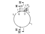
図示されたウォーム駆動のホースクリップは、締め付けストラップ1、ハウジング2及びねじ付けられたシャフト5に頭部4を含む右ねじの締め付けねじ3を含む。締め付けストラップ1は重なり合う端部分6及び7を閉じたウォーム駆動のホースクリップの円周方向に有する(図6)。半径方向外側の端部分6には締め付けストラップ1に型打ち又はエンボスされたほぼ軸方向に延びる溝の形状であるねじ要素8が提供され、そのねじ要素8はねじ付けられたシャフト5のねじ山により結合される。半径方向内側の端部分7は、両端部分6、7及びねじ付けられたシャフト5を取り囲むハウジング2の下部9とぴったりと結合する。ハウジング2は締め付けねじ3をクリップの両円周方向で支持し、ハウジングバンド10を含む。ハウジングバンド10は突合せ継手11(図4、図9、図10、図11)に沿って下部9の領域で結合する端部を有する。ぴったりとした(確実に固締する)結合は、突合せ継手11を画定するハウジングバンド10の縁の互いに錠止する切込みにより形成される。互いに錠止する切込みはハンマーヘッド形状の突起12をハウジングバンド10の1つの端部に、及び突起12に合致するハンマーヘッド形状の切抜き13をハウジングバンド10の他の端部に有する(図9及び図11)。ハンマーヘッド結合12、13の代わりに、鳩尾形結合を提供することも可能である。
【0020】
ハウジング2の下部9は、1つの横方向のへりに、締め付けねじ3の頭部4と向かい合う、2つの半径方向外側に屈曲する舌状突起14の1つをそれぞれ突合せ継手11の反対側に有する。それぞれの舌状突起14は、締め付けストラップ1の半径方向内側の端部分7に提供される開口部15を通って一緒に突出する(図4から図6)。さらにこの横方向のへりが締め付けねじの頭部4に向かって前方に傾斜して突出する(図11)。この構造では、クリップが増大した直線状の押圧力で締め付けられるとき、ねじ頭部4に向き合い及び端部分7の湾曲した内側面に接触する横方向のへりの縁がいくぶん、及び正確に軸方向に延びる横方向のへりと比較して引き延ばされる。従ってそのことにより締め付けストラップ1上に力が及ぼされるせん断作用は軽減され、それにより締め付けストラップ1は破損することなくより高い締め付け力に耐える。ハウジング2の下部9の他の横方向のへり9aは、連続的にまっすぐで溝16上で支持される。溝16は横方向のへり9aの方向に開き締め付けストラップ1の半径方向内側に型押しされる。下部9に向かって開く溝17は、締め付けねじの頭部4の側面にある舌状突起14の両方と共通する開口部15に隣接し、締め付けストラップ1の半径方向内側の端部分に形成される。まっすぐな横方向のへり9aの反対に位置する下部9の端部は、舌状突起14に隣接する下部9の端領域に支持される。締め付けストラップ1の内側の端部分7は半径方向外側に向いて屈曲する部分が存在しない。その屈曲した部分は下部9と結合するため従来技術のウォーム駆動のホースクリップに提供されている。
【0021】
溝16、17は、クリップの円周方向に延び、各溝16、17の半径方向内側の縁は下部9の下側面と整列する。この結合において、縁は半径方向内側の端部分7の内側面への途切れない移行を有する。この方法では、ハウジング下部9及び締め付けストラップ1の内側面間の実質上途切れのない移行には、ハウジング2の下部9に隣接する管、受け口又はその種のもの上のウォーム駆動のホースクリップにより固定されるホースの円周領域について対応する均一の締め付け圧力が配分される。
【0022】
溝16に隣接し、締め付けストラップ1の半径方向内側の端部分7に形成されるさらなる開口部18が提供される。開口部15のように、これら開口部18は溝16、17がそこに形成されるとき、たとえストラップの縦方向の延長に対して横方向に延びる切れ目が締め付けストラップ1に形成され、隣接するストラップ領域は外側にプレスされて溝16、17を形成しても、締め付けストラップ1が破損するのを防ぐ。
【0023】
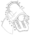
ハウジング2は側方のブラケット19を、締め付けストラップ1上の締め付けねじ3を締め付けねじ3の頭部4からシャフト5への方向に見て右側面にのみ有する。ブラケット19の壁は、締め付けストラップ1の半径方向外側の端部分6の半径方向外側に、締め付けねじのシャフト5の端に隣接して、壁部分22が提供され、壁部分22はブラケット19の半径方向の壁部分21の接線方向にあるハウジング2の頂上部分の湾曲した背20から下方に傾斜する。さらにブラケット19は、締め付けねじシャフト5の中央部分に隣接し、締め付けねじシャフト5の中央部分に寄りかかる湾曲した壁部分23と、湾曲した壁部分23を半径方向の壁部分21と結合する軸方向の壁部分24を有する。
【0024】
湾曲した壁部分23及び軸方向の壁部分24は、ハウジング2の側壁をプレスする又はエンボスすることにより形成される。これと関連して、締め付けねじ3に対して横方向に延びる壁部分25は、下方に傾斜する壁部分22、湾曲する壁部分23及び軸方向の壁部分24間にとどまる。
【0025】
横方向に延びる壁部分25の平面は、締め付けねじ3のほぼ中央部分を横断し、締め付けねじ3は締め付けストラップ1とのねじ結合を提供する。
【0026】
このウォーム駆動のホースクリップにおいて、ハウジング下部9の横方向のへり9a及びその反対側に位置するへり領域はウォーム駆動のホースクリップが締め付けられている又は解除されているとき、溝16及び溝17の開口部の縁26(図16から図18)の半径方向の端表面上で締め付けストラップ1の円周方向に支持される。最も負荷がかかる横方向のへり9aに関して、このことが4つの表面上に支持作用を提供する。従って横方向のへり9a上の全体の支持表面領域は、既知の装置(ドイツ特許19633435C1)の場合のようなたった2つの支持表面領域の場合よりも大きい。既知の装置では、ハウジング下部9のねじ頭部4に背く横方向のへりが開口部の舌状突起のペアの1つに隣接して置かれる2つの表面だけで支持される。その開口部は舌状突起のペアを受け取り、ハウジング下部に提供される横方向の溝の側壁に提供される。従って、ハウジング下部9の最も強く負荷のかかる横方向のヘリ9a上の表面押圧は減少し、ハウジング下部9及び締め付けストラップ1との結合には、締め付けストラップ1の円周方向に、よりきつい力で負荷がかかるが、実質的な変形の原因とはならない。さらに、舌状突起14は、開口部15と結合することにより、突合せ継手11の領域でのハウジングバンド10の2つの端部の堅固な結合に寄与する。
【0027】
図4の右の舌状突起14は締め付けの間、隣接する舌状突起14より強い負荷がかかり、従って左の舌状突起14より横方向に幅広である。さらに、締め付けねじ3の頭部4からシャフト5への方向から見て、締め付けねじ3の右に位置する締め付けストラップ1の縁からの、舌状突起14を受け取る開口部15の間隔aは、締め付けストラップ1の反対に位置する縁からの開口部15の間隔bより小さい。従って、開口部15の1つの縦方向の縁及び締め付けストラップの1つの縁の間に位置する幅がbである支えは、締め付けストラップ1が締め付けられるとき、ねじ要素8のピッチ及び締め付けねじ3のねじ山により、幅aを有する支えよりも多くの負荷がかかり、従って、開口部15の偏心の結果、より大きい断面を有する。また、溝16及び17の開口部の縁26の半径方向内側の領域において、ハウジング下部9の横方向のへりは締め付けストラップ1上で円周方向に支持されうる。
【0028】
ブラケット19は、ウォーム駆動のホースクリップが締め付けられる間、締め付けねじ3の右回転の際にハウジング2の側方の傾斜を防ぐ。なぜなら締め付けねじ3は半径方向外側の端部分6の上側にあるねじ付けられたシャフト5とともに回転する傾向があり、一方で傾斜したねじ要素8のために軸方向の力成分によりブラケット19の方向に側方向の力を強いられるからである。締め付けねじ3を締め付ける際の図4に示される左のハウジングの壁に作用する力は、湾曲する壁部分23を図4において左の外側に屈曲する、すなわち壁部分23を伸ばす傾向にある。しかしこれは、軸方向の壁部分24及び横方向に延びる壁部分25により非常に高い締め付け力のところまでで阻まれる。たとえ締め付けねじの頭部4がハウジング2の開口部の周縁部を越えて突出するフランジ27を有し(図5及び図6)、締め付けの間に軸方向の横軸について締め付けねじ3の回転を防いでも、その締め付け工程の間締め付けねじの頭部4は締め付けストラップ1方向に移動する傾向にあり、こうした回転は非常に高い締め付け力で排除することはできない。このため、ハウジング2の1つの側壁28だけが実質上の平面である、すなわちその反対側に位置する壁部分23及び24間の側壁のように締め付けねじ3に向かって内側に型押しされないだけでなく、下方に傾斜する壁部分22もまっすぐ、すなわち押し下げられない。従ってこの壁部分22は、ハウジング2が一方では拡大しない又は離れないこと、及び他方で軸方向の横軸について締め付けねじ3のトルクに対して撓まないことをさらに確実にする。
【0029】
さらに、下方に傾斜する壁部分22のために、締め付けねじ3のねじ付けられたシャフト5の端部分間の間隔が壁部分22の幅に合致する長さを有し、ハウジングの壁がねじが下方に傾斜する壁部分22の領域でハウジングと接触しないように提供され、従って接触損耗が少なくてすむ。従って締め付けねじ3は長期間にわたって、高い締め付け力の複数の印加及び動作を経た後でも容易に動作状態にとどまることができる。
【0030】
ブラケット19の横方向に延びる壁部分25はねじ要素8が提供される端部分6を結合する締め付けねじ3のねじ付けられたシャフト5の実質上中心部分に位置されるので、横方向に最も負荷のかかるハウジング2のこの領域は非常に固い又は強い。そのため非常に高い締め付け力でも締め付けねじ3によりその領域を拡大する又はばらばらに広げることはできない。
【0031】
締め付けねじの頭部4と反対側のハウジング端部上の角29(図12、図13)は、ホース材料に容易に貫通できず従ってそれに損傷を与えないように丸まっている。
【0032】
締め付けねじの頭部4に位置するハウジング2の端部分には、半径方向内側の縁にタブ30及び31が提供される。タブ30及び31は締め付けねじ3がハウジング2に導入されたあと、ねじ部分(図5及び図6)のない締め付けねじ3の首の下方で屈曲し、締め付けねじの逆回転によりウォーム駆動のホースクリップを開く(解除する)際にハウジング2に対する締め付けねじ3の戻り移動を防ぐ。
【0033】
締め付けねじ3の頭部4に向かい合うハウジング2の頂上部分の端には歯32が提供される。その歯の上に頭部4の半径方向の表面、この場合は頭部4のフランジ27が配置される。締め付けの際、締め付けねじ3の締め付け力すなわちトルクが所定の限界を超えるとき、歯32が変形し、それによりその縁が締め付けねじの頭部4の半径方向の表面と結合する。その後、締め付けストラップ1の引張り応力が締め付け力すなわちトルクをさらに増大しようと試みるときでも、締め付けストラップ1の引張り応力は極めて減少した値だけしか増大せず、それによりストラップの破損の危険が実質上防がれる。これとは対照的に、この所定の締め付け力に到達するまで、つまり歯32が変形する前は、締め付けねじ3は比較的容易に回転でき、実質上いかなる妨害もない。
【0034】
図19から図21までは、図5から図8で概略的にのみ示される締め付けねじ3のねじ山及びねじ要素8を詳細に示している。従って、締め付けストラップ1にエンボスされるねじ要素8及び締め付けねじ3のねじ山35のフランク33、34は、締め付けストラップ1の締め付けに際し締め付けねじ3を締め付けることにより互いに対して押圧され、半径R1及びR2を伴う丸みのある内側及び外側の端部を有する。これらフランク33、34の勾配はほぼ90°である。ねじ要素8のほかのフランク36は半径R 1 及びR 2 より大きい半径R 3 及びR 4 を伴う丸みのある端部を有し、ねじ山35のほかのフランク37は半径R1及びR2より大きい半径R 3 ′及びR 4 ′を伴う丸みのある端部を有する。ねじ要素8のフランク36の外側端での半径R3は、フランク36の内側端での半径R4より小さい。一方、ねじ山35のフランク37の外側端での半径R 3 ′はフランク37の内側端での半径R 4 ′より大きい。ねじ要素8が提供される締め付けストラップ1の端部分6の半径方向内側の側面(図21)は実質上平面である。プレスされた溝の中に提供されるねじ要素8間のねじ山38は、0.2mmから0.5mmの範囲での下部の厚さd1及び0.6mmから1mmの範囲での締め付けストラップの厚さd2に対して0.6mmから1mmの範囲での高さh1を有する。
【0035】
フランク33及び34の勾配は、ほぼ90°のフランク角に対応する。一方、フランク36及び37の勾配は約15°の角βに対応する。ねじ要素8すなわち締め付けストラップ1の半径方向外側の端部分6のねじ山38のこの形状及び締め付けねじ3のねじ山35の形状は以下の利点を有する。フランク33及び34の勾配により、ねじ山35及びねじ要素8は確実に、互いに対して押圧される傾斜したフランクとは対照的に、非常に高い締め付け力でもより高いさらなる半径方向の力成分により外すことができなくなる。小さい半径R1及びR2は、大きい半径と比較して半径方向により長い接触フランクを提供し、従って、締め付けの間減少した半径方向の力成分も提供する。それは締め付けねじ3のねじ山及び締め付けストラップ1のねじ要素8に互いに対して半径方向に離れることを強いる傾向がある。半径R1及びR2と比較して大きい半径R3及びR4は、結果として外側端及び内側端でのねじ山38の幅を大きくし、それによりねじ山が変形する前により高い値に対応した負荷がかけられる。同じことがねじ要素8と実質的に相補的である締め付けねじ3のねじ山35にも当てはまる。小さい半径R2及び大きい半径R4は、相補的な形状を有する鋳造型に対応する歯が、その歯にはすでにほぼ台形又は屋根型形状の先端がねじ要素8を型打ちするために提供されているが、長い耐用年数を有するという利点も有する。なぜなら型が実質上V字形の歯は非常に容易に締め付けストラップ1の材料に押圧されうるからである。前述した高さh1の最大値に対する半径R1からR4の有益な値は以下の通りである。
R1=0.25mm
R2=0.3mm
R3=0.7mm
R4=0.5mm
【0036】
締め付けストラップ1の端部分6の実質上平面の半径方向内側の側面は、プレスされた形状と比較してプレスされたねじが提供され、そのプレスされた形状とは、端部分6の半径方向内側の側面が実質上半径方向外側の側面と同一の方法でプレスの間対応するより低い型を使用することにより形成されたものだが、特に、ウォーム駆動のホースクリップが車両に使用されるときの、締め付けストラップのプレスされた部分と管の受け口上のウォーム駆動のホースクリップにより締め付けられるホース間の振動が原因の摩擦が実質上阻止されるという利点を有する。
【0037】
図22による実施形態は図19から図21の締め付けストラップ1の端部分6と比較して幾分変更した締め付けストラップ1の型打ちされた端部分6を示している。この実施形態では、端部分6の半径方向内側の側面は平面ではなく、わずかに波形で実質上左右対称の配置である。その際波形の最小限度はねじ要素8のそれらとある程度同期して一致し、波形の最大限度はねじ山38のそれらと一致する。しかし、内側の波形の最大限度の半径R5及び最小限度の半径R6は外側の波形の半径よりも極めて大きく、内側の波形の高さh2は外側の波形の高さh1よりもずっと小さい。例えば、半径R5とR6及び高さh2について、他のすべての寸法の値が図19から図21の先行の実施形態と同一であると、以下の値、つまり
R5=2mm
R6=2mm
h2=0.1mmから0.3mmが好ましい。
【0038】
その値は個々にウォーム駆動のホースクリップ又は締め付けられるホースの名目上の径、締め付けストラップの幅及び締め付けストラップの材料に左右される。締め付けストラップ1の端部分6の半径方向内側の側面の軽い波形は、摩擦に関して事実上無視できる。しかし、このことは下部の厚さd1が前述の実施形態におけるより幾分大きいという利点を有する。なぜなら前述の実施形態と同じねじ山38の高さh1及びストラップの厚さd2に対して、ねじ山38の外側端がより高めに位置し、それによりねじ要素8及びねじ山38を形成する道具又は型がストラップの材料にそれほど深く貫通できず、従ってねじ山38間の下部を大いに圧縮してはならないからである。これは前述の実施形態のねじ要素8及びねじ山38に対して使用されるプレスの道具と比較して、プレスの型又は道具の耐用年数を非常に増大させる結果となる。
【0039】
本発明の具体的な実施形態が発明の原理を図示して詳細に示され及び記述される一方、本発明はこうした原理から離れることなく別の方法でも実施されうることが理解される。
【図面の簡単な説明】
【図1】 本発明によるウォーム駆動のホースクリップの開状態の側面図である。
【図2】 本発明によるウォーム駆動のホーススクリップの図1の位置に対して90度回転した位置の側面図を示している。
【図3】 図1のIII−IIIの断面を示している。
【図4】 図1のIV−IVの断面を示している。
【図5】 図2のV−Vの断面を示している。
【図6】 図5と同じ断面図だが、クリップの閉状態を示している。
【図7】 本発明によるクリップの開状態の斜視拡大図である。
【図8】 図7の丸で囲まれた部分により示される本発明によるクリップの拡大詳細を示している。
【図9】 本発明によるウォーム駆動のホースクリップのハウジングの斜視図である。
【図10】 より小さい尺度での図9によるハウジングの正面図である。
【図11】 図10によるハウジングの下面図である。
【図12】 図10によるハウジングの右側面図である。
【図13】 図10によるハウジングの左側面図である。
【図14】 図10によるハウジングの上面図である。
【図15】 本発明によるウォーム駆動のホースクリップの締め付けストラップの斜視図である。
【図16】 締め付けストラップの側面図である。
【図17】 図15の丸で囲まれた部分で示される締め付けストラップの拡大詳細を示している。
【図18】 ウォーム駆動のホースクリップの締め付けストラップの端部分の下面図である。
【図19】 ハウジングが離脱した領域の本発明によるウォーム駆動のホースクリップのクロージャの軸断面である。
【図20】 図19の拡大した軸断面である。
【図21】 図20の一部を分離した図である。
【図22】 図21と同じ詳細だが、締め付けストラップの外側の端部分の半径方向内側の側面がわずかに波形である。
【符号の説明】
1 締め付けストラップ
2 ハウジング
3 締め付けねじ
4 頭部
5 ねじ付けられたシャフト
6 半径方向外側の端部分
7 半径方向内側の端部分
8 ねじ要素
9 ハウジングの下部
9a 横方向のへり
10 ハウジングバンド
11 突合せ継手
12 ハンマーヘッド形状の突起
13 ハンマーヘッド形状の切抜き
14 舌状突起
15 開口部
16 溝
17 溝
18 開口部
19 側方のブラケット
20 湾曲した背
21 半径方向の壁部分
22 下方に傾斜する壁部分
23 湾曲した壁部分
24 軸方向の壁部分
25 横方向に延びる壁部分
26 開口部の縁
27 フランジ
28 側壁
29 角
30 タブ
31 タブ
32 歯
33 フランク
34 フランク
35 ねじ山
36 フランク
37 フランク
38 ねじ山 [0001]
BACKGROUND OF THE INVENTION
The present invention relates to a worm-driven hose clip including a clamping strap, a housing and a clamping screw including a head and a threaded shaft. The fastening strap has overlapping end portions. One located radially outward of the end portion is provided with a screw element that couples the threaded shaft, the end portion located radially inward enclosing the end portion and the threaded shaft of the clamping screw. Connect securely to the lower part of the housing. The housing supports the clamping screw in both the circumferential directions of the clip. The housing includes a housing band, the ends of which define a butt joint in the lower region of the housing and are joined together by locking notches provided at edges that define the butt joint. The lower part of the housing is provided with one of two tongue projections on the edges facing the heads of the clamping screws on both sides of the butt joint, each tongue projecting radially outwards, Projects together in the opening of the inner end portion.
[0002]
[Prior art]
In a known worm-driven hose clip of this kind (
[0003]
Furthermore, there is a risk that the axial side walls of the folded or bent part are pulled apart with a very high clamping force, whereby the folded part is deformed and returns to the plane of the clamping strap. It can happen that the tongue no longer couples the interrelated opening provided in the lateral edge of the lower part of the housing against the head of the clamping screw. In addition, the folded portion increases the radial spacing of the threaded screw shaft from the hose secured by the clip on the tube, thereby increasing the bending action time of the return deformation acting on the folded portion. Despite this, known hose clips withstand relatively high clamping forces. This results in the person handling the clip trying to further increase the tension in order to secure the hose as tightly as possible. This results in damage or separation of the tightening strap in the strap region where an embossed screw element cooperating with the threaded screw shaft is provided.
[0004]
[Problems to be solved by the invention]
The object of the present invention is still fairly loaded and easily installed, but substantially eliminates the risk of over-tightening during the clamping action, while being secured by a tube or the like and a hose clip on the tube. The object is to provide a worm-driven hose clip of the kind described above which provides a tight connection between the hoses.
[0005]
[Means for Solving the Problems]
According to the invention, this has a straight configuration with a continuous lateral edge at the bottom of the housing against the head of the clamping screw, and is embossed radially inward into the clamping strap which opens towards this lateral edge or Supported by a groove to be embossed, a groove that opens toward the bottom is common to the tongue-like projection and is adjacent to the opening provided on the side of the head of the tightening screw and a tightening strap, the lower part of which is on this groove Being supported, the inner end of the tightening strapInReceive the bottom(Ie join)Folded part facing radially outwardDoes not existAnd the grooves extend in the circumferential direction of the clip, and the radially inner edge of each grooveAlignThis is achieved by having a continuous transition to the inner surface of the radially inner end portion.
[0006]
In this solution, the head of the clamping screwAnd the other sideA tongue-like projection on the lateral edge of the lower part of the housing is not required, thereby not only removing the tongue-like configuration but also simplifying the housing suspension at the radially inner end portion of the clamping strap. This lateral edge is most loaded during tightening, so if it is supported by two grooves, it is supported by the edge of the groove opening at four locations. Compared to a single groove, this lateral edge load capacity is thereby doubled as a result of the reduction of the surface pressure. Eliminating the groove-shaped folded or bent portion that receives the lower housing portion at the radially inner end portion of the tightening strap is impossible for the strap to extend as a result of the return deformation of the folded portion when tightening the tightening strap Has the advantage. And in this way, the two tongue projections that safely join the opening of the fastening strap with the screw head maintain their position in the opening and prevent them from leaving the lower part of the housing with too high a clamping force. This is because the tongue is always supported along the side on the edge of the common opening of the fastening strap.
[0007]
Despite the elimination of the folded portion, the groove ensures that there is an uninterrupted transition between the lower surface of the housing and the inner surface of the radially inner end portion of the clamping strap, as occurs in the case of a stepping transition. Prevents the possibility of a decrease in the clamping force in the radial direction. TherebyClipHorizontal edge area at the bottom of the housingsoEven provides a uniform radial pressure on the hose, so that the connection between the hose and the tube in this region remains tight. The elimination of the folded part has the further advantage that the screw shaft has a corresponding minimal distance from the hose and the bending is too greatMomentRisk of tightening straps deforming via existing folded parts as a result of removingThe benefits of removingHave
[0008]
Preferably, the radially outer side fastening strap has a series of parallel grooves that are arranged inclining relative to the longitudinal direction of the fastening strap and form a screw element that couples with the thread of the fastening screw, and its radial direction It is provided that the inner side is planar or slightly corrugated, with the maximum height of the corrugation being up to 60% of the maximum lower thickness of the screw element. In this configuration, the radius of the housingdirectionThe height ofScrew elements provided on the radially outer end portion of the fastening strap project from the radially inner side of this end portionDecrease relative to tightening strap configurationTo do.Correspondingly, the play between the threaded shaft of the clamping screw and the radially inner end portion of the clamping strap is such that the clip opens, i.e. when the radially outer end portion of the clamping strap is located outside the housing. Decrease. thisLikeFor UzingWith positive rockFixedThe tightening screwBy contacting the radially inner end of the fastening strap, the housingpivotTo the angular position of the shaft in the circumferential directionPivotTongue processButHousing removed from common openingButSeparate from the fastening strapPrevent.
[0009]
When the height of the corrugation on the inner surface of the radially outer end portion of the tightening strap is almost zero, there is virtually no friction between this corrugation and the tightened hose. On the other hand, the relatively slight corrugation in the area of the groove forming the screw element already prevents the groove area of the clamping strap from becoming too thin during stamping, which prevents the clamping strap from being ruptured or damaged in this area. prevent. Corrugated threadBetweenIt is also possible to maintain a somewhat greater lower thickness in the groove region. This contributes to an increase in the service life of the stamping dies used to construct or manufacture the screw elements of the clamping strap.
[0010]
According to a preferred configuration, the screw element of the fastening strap and the screw of the fastening screwMountain'sOn the flank, the flank is pressed against each other during clamping, providing a curved portion of constant radius at its outer and inner ends, and of an extended (spread or flat lying) clamping strap For Frank'sSlopeIs approximately 90 ° and screw elements and screwsMountain'sThe flank of the other flank has a larger radius than the ends of the flank pressed against each other at its ends and reduced flank compared to the flank pressed against each otherSlopeIt is in having. On the one hand, the structure of the screw elements of this tightening strap, on the other hand, the screw of the tightening screwMountain'sScrew elements and screws depending on configurationOn the mountainAs a result, a higher load can be applied. Thus, screw elements and screwsMountainThe longer and therefore the larger radius surfaces bond to each other with a corresponding reduced surface pressure and the corresponding complementary casting or stamping mold has a longer service life.
[0011]
The radii at the ends of the flank that are pressed against each other while tightening the clamping screw are substantially the same, and the flank of the screw element relative to the other flankOutsideThe radius at the end isInner edgeSmaller than the radius at the other hand, screwNo fuRankOutsideThe radius at the end isInner edgeThis can be further improved when larger than the radius at.
[0012]
Furthermore, it can be provided that the housing is embodied with a lateral bracket that is only on the right side (as viewed from the direction of the head of the clamping screw to the shaft when the clamping screw is on the clamping strap). The bracket wall has a fastening screw shaft on the radially outer end of the radially outer end of the fastening strap.AheadThe clamping screw shaft adjacent to the end and tangential to the radial wall portion of the bracket and adjacent to the central portion of the clamping screw shaft, and a wall portion inclined downwardly from the curved back of the upper surface of the housing. A curved wall portion leaning against the central portion of the wall and an axial wall portion connecting the curved wall portion with the radial wall portion. This bracket prevents the housing from tilting sideways in the direction of rotation of the clamping screw. The curved wall portion contributes to guiding the clamping screw tangentially to the clip. The downwardly inclined wall portion prevents the curved wall portion and the axial wall portion from spreading during clamping. At the same time, the downwardly inclined wall part reduces the contact surface between the threaded shaft thread of the clamping screw and the housing wall, so that the thread in the area of the downwardly inclined wall part receives less wear. Absent. Therefore, the tightening screwMultiple actionsAnd it can rotate easily even after rotation. Therefore, the torque required to tighten the tightening screw is long-term use.BetweenRemain minimal.
[0013]
Curved wall and axial wall sectionspressSo that the wall portion extending transversely to the clamping screw remains between the downwardly inclined wall portion, the curved wall portion and the axial wall portion. thisIsOn the side wall of the racketAgainst expansionProvides high rigidity.
[0014]
Preferably, the plane of the laterally extending wall portion is such that the clamping screw provides a threaded connection to the clamping strap.Cross sectionAlmost centralIntersect withTo do. Within the region of the central portion of the clamping screw that provides a threaded connection to the clamping strap, the housing is subjected to particularly high forces that tend to expand or disengage the housing. In the position described above, the laterally extending wall portion particularly counteracts this expanding tendency.
[0015]
In addition, the top surface of the housing facing the head of the clamping screwEdge ofIs provided with a tooth, on which the radial surface of the head located transverse to the screw axis is arranged. When the upper limit of the clamping force is exceeded, deformation of the tooth edges and deformation of the radial surface of the head results in the clamping screw being able to rotate only with very high friction, so that the clip is only to a limited extent. Further tightening is not possible. This prevents overloading of the clip that would otherwise cause damage to the tightening strap.
[0016]
Furthermore, the lower part of the housing in the circumferential direction of the clip has a curvature, and the radius of the curvature substantially corresponds to the curvature of the circumferential radius of the hose clamped by the clip on the tube, the lower circumferential part Is shorter than the top surface of the housing and tightens the strapEnd ofThe maximum possible number of screw parts of the clamping screwpressAlternatively, it may be provided to couple with a screw element provided by embossing. In this configuration, the individual screws of the clamping screwMountain rangeAnd / or overloading of the screw elements of the tightening strap is avoided.
[0017]
In addition, when viewed from the head of the tightening screw in the shaft direction, the distance between the openings receiving the tongues from the edge of the tightening strap located to the right of the tightening screw is such that the opening from the opposite edge of the tightening strap is It is beneficial when it is smaller than the interval. The left support located between the left longitudinal edge of the opening and the left edge of the tightening strap, as viewed from the direction of the head of the tightening screw, towards the shaft of the tightening screw, is the opposite side during tightening of the tightening strap Is more strongly loaded than the support of the opening, and as a result of the eccentricity of the opening, it has a larger cross-section and therefore the load is considerably higher than the support located on the opposite side defining the opening.
[0018]
Therefore, the edge of the lower part of the housing that faces the head of the clamping screw is inclined with respect to the tongue-like projection.,Projects in the direction toward the head. In this method, shearing of the edge of this lip at the bottom of the housing on the tightening strapActionIs reduced compared to a lip extending perpendicular to the circumferential direction of the curved fastening strap.
[0019]
DETAILED DESCRIPTION OF THE INVENTION
The illustrated worm-driven hose clip includes a clamping
[0020]
The
[0021]
The
[0022]
A
[0023]
The
[0024]
The
[0025]
The plane of the laterally extending
[0026]
In this worm-driven hose clip, the lateral edge 9a of the
[0027]
The
[0028]
The
[0029]
Furthermore, because of the downwardly
[0030]
The laterally extending
[0031]
Screw head 4And the other sideThe corner 29 (FIGS. 12, 13) on the housing end is rounded so that it cannot easily penetrate the hose material and thus damage it.
[0032]
[0033]
The top part of the
[0034]
FIGS. 19 to 21 show in detail the thread of the clamping
[0035]
R1= 0.25mm
R2= 0.3mm
RThree= 0.7mm
RFour= 0.5mm
[0036]
The substantially plane radially inner side of the
[0037]
The embodiment according to FIG. 22 shows a
RFive= 2mm
R6= 2mm
h2= 0.1 mm to 0.3 mm is preferable.
[0038]
Its value depends on the nominal diameter of the worm-driven hose clip or hose to be tightened, the width of the tightening strap and the material of the tightening strap. The light corrugation on the radially inner side of the
[0039]
While specific embodiments of the invention have been shown and described in detail, illustrating the principles of the invention, it is understood that the invention can be practiced otherwise than without departing from such principles.
[Brief description of the drawings]
FIG. 1 is a side view of an open state of a worm-driven hose clip according to the present invention.
FIG. 2 shows a side view of a worm-driven hose scrip according to the present invention in a position rotated 90 degrees with respect to the position of FIG.
FIG. 3 shows a cross section taken along line III-III in FIG.
4 shows a cross section taken along line IV-IV in FIG.
5 shows a cross section taken along line V-V in FIG.
6 is a cross-sectional view similar to FIG. 5, but showing the clip closed. FIG.
FIG. 7 is an enlarged perspective view of a clip according to the present invention in an open state.
8 shows an enlarged detail of a clip according to the invention indicated by the circled part of FIG.
FIG. 9 is a perspective view of a worm-driven hose clip housing according to the present invention.
10 is a front view of the housing according to FIG. 9 on a smaller scale.
11 is a bottom view of the housing according to FIG. 10;
12 is a right side view of the housing according to FIG. 10;
13 is a left side view of the housing according to FIG.
14 is a top view of the housing according to FIG. 10;
FIG. 15 is a perspective view of a tightening strap of a worm-driven hose clip according to the present invention.
FIG. 16 is a side view of a tightening strap.
FIG. 17 shows an enlarged detail of the tightening strap indicated by the circled portion of FIG.
FIG. 18 is a bottom view of an end portion of a tightening strap of a worm-driven hose clip.
FIG. 19 is an axial cross-section of a worm-driven hose clip closure according to the present invention in a region where the housing is detached.
20 is an enlarged axial cross section of FIG. 19;
FIG. 21 is a diagram in which a part of FIG. 20 is separated.
FIG. 22 is the same detail as FIG. 21, but the radially inner side of the outer end portion of the tightening strap is slightly corrugated.
[Explanation of symbols]
1 Tightening strap
2 Housing
3 Tightening screw
4 heads
5 Screwed shaft
6 Radial outer edge
7 Radial inner edge
8 Screw elements
9 Lower part of housing
9a Horizontal edge
10 Housing band
11 Butt joint
12 Hammerhead shaped protrusion
13 Hammerhead cutout
14 Tongue process
15 opening
16 groove
17 Groove
18 opening
19 Side bracket
20 Curved back
21 Radial wall
22 Wall part which inclines downward
23 Curved wall
24 Axial wall part
25 Wall part extending in the horizontal direction
26 Edge of opening
27 Flange
28 side walls
29 corners
30 tabs
31 tabs
32 teeth
33 Frank
34 Frank
35 screwsMountain
36 Frank
37 Frank
38 screwsMountain
Claims (10)
頭部(4)及びねじ付けられたシャフト(5)を含む締め付けねじ(3)と、
前記重なり合う端部分(6、7)及び前記締め付けねじ(3)の前記ねじ付けられたシャフト(5)を取り囲むハウジング(2)とを含み、
前記重なり合う端部分の半径方向外側に位置する1つ(6)に前記ねじ付けられたシャフト(5)と結合するねじ要素(8)が提供され、
前記重なり合う端部分の半径方向内側に位置する1つ(7)が前記ハウジング(2)の下部(9)と確実に固締するよう結合し、前記ハウジング(2)が前記締め付けねじ(3)をウォーム駆動のホースクリップの円周方向に支持し、
前記ハウジング(2)が端部を有するハウジングバンド(10)を有し、前記端部が前記ハウジング(2)の下部(9)に突合せ継手(11)を形成するように結合され前記突合せ継手(11)を画定する縁を有し、前記縁が互いにかみ合う切込み(12、13)を有して前記突合せ継手(11)を固定し、
前記ハウジングの下部(9)が前記頭部(4)と向き合う第1の横方向のへりを有し、該第1の横方向のへりが前記突合せ継手(11)の反対側にそれぞれ突出する舌状突起(14)を有し、該舌状突起(14)は前記締め付けストラップ(1)の半径方向外側に屈曲し、前記舌状突起(14)は前記締め付けストラップ(1)の半径方向内側の端部分(7)にもうけられる開口部(15)の中に一緒に突出し、
前記締め付けねじ(3)の頭部(4)にと反対側の前記ハウジング(2)の下部(9)が連続するまっすぐな構成の第2の横方向のへり(9a)を有し、
前記締め付けストラップ(1)が前記締め付けストラップ(1)から半径方向内側にプレスされる第1の溝(16)を有し、
前記第2の横方向のへり(9a)が前記第1の溝(16)上で支持され、前記第1の溝(16)が前記第2の横方向のへり(9a)に向かって開き、
前記締め付けストラップ(1)が前記舌状突起(14)に共通に前記頭部(4)の近傍に配置される開口部(15)に隣接する第2の溝(17)を有し、前記第2の溝(17)が前記下部(9)に向かって開き、前記下部(9)が前記第2の溝(17)上で支持され、
前記締め付けストラップ(1)の半径方向内側の端部分(7)には前記下部(9)と結合するための半径方向外側に向いて屈曲する部分が存在せず、
前記第1及び第2の溝(16、17)が前記ウォーム駆動のホースクリップの円周方向に延び、前記第1及び第2の溝(16、17)のそれぞれの半径方向内側の縁が前記下部(9)の底面と整列し、前記半径方向内側の端部分(7)の内側面への連続的な移行を有し、
前記舌状突起(14)が突出する単一の前記開口部(15)が、前記締め付けねじ(3)の前記頭部(4)から前記ねじ付けられたシャフト(5)への方向から見て、前記締め付けねじ(3)の右に位置する前記締め付けストラップ(1)の第1の縁からの間隔(a)を有し、前記間隔(a)が前記第1の縁の反対側の前記締め付けストラップ(1)の第2の縁からの前記開口部(15)の間隔(b)より小さいことを特徴とする、ウォーム駆動のホースクリップ。 A clamping strap (1) having overlapping end portions (6, 7);
A clamping screw (3) comprising a head (4) and a threaded shaft (5);
A housing (2) enclosing the overlapping end portions (6, 7) and the threaded shaft (5) of the clamping screw (3);
The screw Tagged shaft (5) screw element (8) that binds are provided in one (6) located radially outward of the overlapping end portions,
One (7) located radially inward of the overlapping end portions is coupled to be securely fastened to the lower portion (9) of the housing (2), and the housing (2) connects the fastening screw (3). Support the worm-driven hose clip in the circumferential direction,
The housing (2) has a housing band (10) having an end, and the end is joined to form a butt joint (11) in a lower part (9) of the housing (2). 11) having an edge defining the edge and having an incision (12, 13) in which the edges engage with each other to secure the butt joint (11);
Tongue lower portion of the housing (9) has a first lateral edge facing the said head (4), respectively protrude to the opposite side of the first lateral edge is the butt joint (11) Jo protrusion has a (14), said tongue (14) is bent radially outward of the clamping strap (1), the radius direction inner side of the tongue (14) the tightening strap (1) project together into an opening provided at the end portion (7) (15),
A second lateral edge (9a) of a straight configuration in which the lower part (9) of the housing (2) opposite the head (4) of the clamping screw (3) is continuous;
The fastening strap (1) has a first groove (16) pressed radially inward from the fastening strap (1);
The second lateral edge (9a) is supported on the first groove (16), the first groove (16) opens towards the second lateral edge (9a);
The fastening strap (1) has a second groove (17) adjacent to an opening (15) arranged in the vicinity of the head (4) in common with the tongue-like projection (14) , Two grooves (17) open towards the lower part (9), the lower part (9) being supported on the second groove (17),
The end portion (7) on the inner side in the radial direction of the fastening strap (1) does not have a portion bent toward the outer side in the radial direction for coupling with the lower portion (9),
The first and second grooves (16, 17) extend in the circumferential direction of the worm-driven hose clip, and the radially inner edges of the first and second grooves (16, 17) are aligned with the bottom surface of the lower (9), have a continuous transition to the inner surface of the radially inner end portion (7),
The single opening (15) from which the tongue-like protrusion (14) protrudes is viewed from the head (4) of the clamping screw (3) to the screwed shaft (5). , Having a spacing (a) from a first edge of the clamping strap (1) located to the right of the clamping screw (3), the spacing (a) being the clamping on the opposite side of the first edge Worm-driven hose clip, characterized in that it is smaller than the spacing (b) of the opening (15) from the second edge of the strap (1).
それらの半径方向外側の端部は第1の半径(R1)を、半径方向内側の端部はこれと同じ第1の半径(R2)を有し、
前記第1のフランクは前記締め付けストラップ(1)が延びている時ほぼ90°の第1の勾配を有し、
前記ねじ要素(8)の第2のフランク(36)は前記第1の半径より大きい第2の半径(R3)及び第3の半径(R4)を伴う端部を有し、
前記ねじ山(35)の第3のフランク(37)は前記第1の半径より大きい第2の半径(R3′)及び第3の半径(R4′)を伴う端部を有し、
前記第2のフランク(36)及び前記第3のフランク(37)は前記第1の勾配より小さい第2の勾配(β)を有することを特徴とする、請求項2に記載のウォーム駆動のホースクリップ。 The first flank (33 ) of the screw element (8) and the first flank (34 ) of the thread (35) of the clamping screw (3) are pressed against each other;
Their radially outer ends have a first radius (R 1 ), their radially inner ends have the same first radius (R 2 ),
The first flank has a first slope of approximately 90 ° when the fastening strap (1) is extended;
The second flank (36) of the screw element (8) has an end with a second radius (R 3 ) and a third radius (R 4 ) greater than the first radius;
A third flank (37) of the thread (35) has an end with a second radius (R 3 ') and a third radius (R 4 ') greater than the first radius;
The worm-driven hose of claim 2, wherein the second flank (36) and the third flank (37) have a second slope (β) that is less than the first slope. clip.
前記ねじ要素(8)の第2のフランク(36)に関して該フランク(36)の外側端の半径(R3)は内側端の半径(R4)より小さく、
前記ねじ山(35)の第3のフランク(37)に関して該フランク(37)の外側端の半径(R3′)は内側端の半径(R4′)より大きい、ことを特徴とする、請求項3に記載のウォーム駆動のホースクリップ。The radius (R 1 ) of the radially outer end and the radius (R 2 ) of the radially inner end of the first flank (33, 34) pressed against each other when the clamping screw (3) is tightened. ) Are substantially the same,
For the second flank (36) of the screw element (8), the radius (R 3 ) of the outer end of the flank (36) is smaller than the radius (R 4 ) of the inner end,
The radius (R 3 ') of the outer end of the flank (37) is greater than the radius (R 4 ') of the inner end with respect to the third flank (37) of the thread (35), Item 4. The worm-driven hose clip according to item 3.
Applications Claiming Priority (2)
| Application Number | Priority Date | Filing Date | Title |
|---|---|---|---|
| DE2002114663 DE10214663A1 (en) | 2002-04-03 | 2002-04-03 | Worm drive hose clip |
| EP20020015824 EP1351005B1 (en) | 2002-04-03 | 2002-07-16 | Worm drive clamp |
Publications (3)
| Publication Number | Publication Date |
|---|---|
| JP2004036881A JP2004036881A (en) | 2004-02-05 |
| JP2004036881A5 JP2004036881A5 (en) | 2006-07-27 |
| JP4042609B2 true JP4042609B2 (en) | 2008-02-06 |
Family
ID=28676044
Family Applications (1)
| Application Number | Title | Priority Date | Filing Date |
|---|---|---|---|
| JP2003099142A Expired - Lifetime JP4042609B2 (en) | 2002-04-03 | 2003-04-02 | Worm drive hose clip |
Country Status (4)
| Country | Link |
|---|---|
| US (1) | US6845549B2 (en) |
| JP (1) | JP4042609B2 (en) |
| CA (1) | CA2424343C (en) |
| RU (1) | RU2258861C2 (en) |
Families Citing this family (15)
| Publication number | Priority date | Publication date | Assignee | Title |
|---|---|---|---|---|
| US7594304B2 (en) * | 2004-04-12 | 2009-09-29 | Takagi Mfg. Co., Ltd. | Clamp device for connection |
| US20060064854A1 (en) * | 2004-09-27 | 2006-03-30 | Dian-Tai Chen | Hose clamp |
| SE528956C2 (en) | 2005-09-06 | 2007-03-20 | Aba Sweden Ab | Hose clamp for use in engine compartments has band, clamping screw which are immovably connected to locking portion are arranged for fixed attachment to hose |
| US7652571B2 (en) | 2006-07-10 | 2010-01-26 | Scott Technologies, Inc. | Graphical user interface for emergency apparatus and method for operating same |
| DE102006041429A1 (en) * | 2006-09-04 | 2008-03-20 | Metabowerke Gmbh | Electric hand tool |
| US7464444B2 (en) * | 2006-11-21 | 2008-12-16 | Dian-Tai Chen | Hose clamp |
| US20090083950A1 (en) * | 2007-10-01 | 2009-04-02 | Thomas Corogin | Clamp |
| DE102007058319B4 (en) * | 2007-12-04 | 2013-06-27 | Norma Germany Gmbh | Worm drive hose clip |
| DE102009051128A1 (en) * | 2009-10-28 | 2011-05-05 | Norma Germany Gmbh | hose clamp |
| JP2011214653A (en) * | 2010-03-31 | 2011-10-27 | Takagi Manufacturing Co Ltd | Clamp device for connection |
| DE102010035755B4 (en) * | 2010-08-28 | 2014-10-30 | Norma Germany Gmbh | Hose clamp with a clamping screw, clamping screw and tool for driving the clamping screw |
| US9541226B2 (en) | 2012-01-10 | 2017-01-10 | Ford Global Technologies, Llc | Anti-rotation worm gear clamp |
| CA2806965C (en) * | 2012-11-06 | 2015-04-21 | Sogyo Co., Ltd. | A strap-band type connecting device |
| RU183286U1 (en) * | 2018-04-27 | 2018-09-17 | Общество с ограниченной ответственностью "ПКФ Мега-Фикс" | WRAP CLAMP |
| CN113958583B (en) * | 2021-11-24 | 2024-03-01 | 河北展宇机电科技有限公司 | Fastening piece |
Family Cites Families (10)
| Publication number | Priority date | Publication date | Assignee | Title |
|---|---|---|---|---|
| US3950830A (en) * | 1974-09-03 | 1976-04-20 | Standard-Thomson Corporation | Quick attachment and release worm gear type hose clamp |
| DE2800824C2 (en) * | 1978-01-10 | 1983-07-14 | Rasmussen Gmbh, 6457 Maintal | Worm drive clamp |
| US4257149A (en) * | 1978-12-07 | 1981-03-24 | Tridon Limited | Band clamp device |
| DE2854676C2 (en) | 1978-12-18 | 1984-11-29 | Rasmussen Gmbh, 6457 Maintal | Worm drive clamp |
| US4473928A (en) * | 1980-11-20 | 1984-10-02 | Tridon Limited | Hose clamps |
| ES281033Y (en) * | 1984-08-09 | 1986-07-16 | Mikalor S.A. | PERFECTED CLAMP |
| US5560087A (en) * | 1993-07-21 | 1996-10-01 | Stant Corporation | Laterally secure hose-clamp assembly |
| DE9419543U1 (en) | 1994-12-06 | 1995-03-23 | Gemi Metallwarenfabrik Gmbh & | Hose clamp |
| DE19633435C1 (en) | 1996-08-20 | 1998-02-12 | Rasmussen Gmbh | Worm thread clamp |
| DE10026020B4 (en) * | 2000-05-25 | 2004-12-16 | Rasmussen Gmbh | Worm drive hose clip |
-
2003
- 2003-04-02 US US10/405,838 patent/US6845549B2/en not_active Expired - Lifetime
- 2003-04-02 RU RU2003109224/06A patent/RU2258861C2/en active
- 2003-04-02 JP JP2003099142A patent/JP4042609B2/en not_active Expired - Lifetime
- 2003-04-02 CA CA002424343A patent/CA2424343C/en not_active Expired - Fee Related
Also Published As
| Publication number | Publication date |
|---|---|
| US6845549B2 (en) | 2005-01-25 |
| US20030188402A1 (en) | 2003-10-09 |
| CA2424343C (en) | 2007-07-03 |
| JP2004036881A (en) | 2004-02-05 |
| AU2003203218A1 (en) | 2003-10-23 |
| RU2258861C2 (en) | 2005-08-20 |
| CA2424343A1 (en) | 2003-10-03 |
Similar Documents
| Publication | Publication Date | Title |
|---|---|---|
| JP4042609B2 (en) | Worm drive hose clip | |
| CA1288218C (en) | Hose band | |
| EP1861628B1 (en) | T-bolt clamp quick attach latch | |
| JP3237643B2 (en) | clip | |
| GB2149037A (en) | Pipe coupling | |
| US5707190A (en) | Blind bolt assembly | |
| US20230383877A1 (en) | Pre-assembled pipe coupling with manually manipulatable segments | |
| JP3473594B2 (en) | Worm gear drive hose clamp | |
| US4712278A (en) | Earless clamp structure | |
| JPH0217758B2 (en) | ||
| HU217602B (en) | Clamp structure | |
| JPS5822676B2 (en) | Hose band tightening fittings | |
| EP0064150B1 (en) | Pipe repair clamp | |
| JP2947239B2 (en) | Worm drive clamp | |
| JPH06129581A (en) | Reusable clamp structure having no lug | |
| JP3415642B2 (en) | Clamp structure | |
| JPH07198079A (en) | Lug-less or stepless clamp structure | |
| RU2003109224A (en) | WRAP THREADED CLIP | |
| JP3945469B2 (en) | Hose clamp and hose connection to pre-position hose clamp | |
| US5906453A (en) | Joint forming devices | |
| US5940939A (en) | One-piece flat band clamp | |
| JPS6220436B2 (en) | ||
| JP3420248B2 (en) | Metal clip | |
| JPH0135110Y2 (en) | ||
| JPH0353108Y2 (en) |
Legal Events
| Date | Code | Title | Description |
|---|---|---|---|
| A131 | Notification of reasons for refusal |
Free format text: JAPANESE INTERMEDIATE CODE: A131 Effective date: 20051220 |
|
| A601 | Written request for extension of time |
Free format text: JAPANESE INTERMEDIATE CODE: A601 Effective date: 20060320 |
|
| A602 | Written permission of extension of time |
Free format text: JAPANESE INTERMEDIATE CODE: A602 Effective date: 20060327 |
|
| A521 | Request for written amendment filed |
Free format text: JAPANESE INTERMEDIATE CODE: A523 Effective date: 20060612 |
|
| A524 | Written submission of copy of amendment under article 19 pct |
Free format text: JAPANESE INTERMEDIATE CODE: A524 Effective date: 20060612 |
|
| A131 | Notification of reasons for refusal |
Free format text: JAPANESE INTERMEDIATE CODE: A131 Effective date: 20070123 |
|
| A521 | Request for written amendment filed |
Free format text: JAPANESE INTERMEDIATE CODE: A523 Effective date: 20070409 |
|
| TRDD | Decision of grant or rejection written | ||
| A01 | Written decision to grant a patent or to grant a registration (utility model) |
Free format text: JAPANESE INTERMEDIATE CODE: A01 Effective date: 20071023 |
|
| A61 | First payment of annual fees (during grant procedure) |
Free format text: JAPANESE INTERMEDIATE CODE: A61 Effective date: 20071105 |
|
| R150 | Certificate of patent or registration of utility model |
Ref document number: 4042609 Country of ref document: JP Free format text: JAPANESE INTERMEDIATE CODE: R150 Free format text: JAPANESE INTERMEDIATE CODE: R150 |
|
| FPAY | Renewal fee payment (event date is renewal date of database) |
Free format text: PAYMENT UNTIL: 20101122 Year of fee payment: 3 |
|
| FPAY | Renewal fee payment (event date is renewal date of database) |
Free format text: PAYMENT UNTIL: 20101122 Year of fee payment: 3 |
|
| FPAY | Renewal fee payment (event date is renewal date of database) |
Free format text: PAYMENT UNTIL: 20111122 Year of fee payment: 4 |
|
| R250 | Receipt of annual fees |
Free format text: JAPANESE INTERMEDIATE CODE: R250 |
|
| FPAY | Renewal fee payment (event date is renewal date of database) |
Free format text: PAYMENT UNTIL: 20121122 Year of fee payment: 5 |
|
| R250 | Receipt of annual fees |
Free format text: JAPANESE INTERMEDIATE CODE: R250 |
|
| FPAY | Renewal fee payment (event date is renewal date of database) |
Free format text: PAYMENT UNTIL: 20121122 Year of fee payment: 5 |
|
| FPAY | Renewal fee payment (event date is renewal date of database) |
Free format text: PAYMENT UNTIL: 20131122 Year of fee payment: 6 |
|
| R250 | Receipt of annual fees |
Free format text: JAPANESE INTERMEDIATE CODE: R250 |
|
| R250 | Receipt of annual fees |
Free format text: JAPANESE INTERMEDIATE CODE: R250 |
|
| R250 | Receipt of annual fees |
Free format text: JAPANESE INTERMEDIATE CODE: R250 |
|
| R250 | Receipt of annual fees |
Free format text: JAPANESE INTERMEDIATE CODE: R250 |
|
| R250 | Receipt of annual fees |
Free format text: JAPANESE INTERMEDIATE CODE: R250 |
|
| R250 | Receipt of annual fees |
Free format text: JAPANESE INTERMEDIATE CODE: R250 |
|
| R250 | Receipt of annual fees |
Free format text: JAPANESE INTERMEDIATE CODE: R250 |
|
| R250 | Receipt of annual fees |
Free format text: JAPANESE INTERMEDIATE CODE: R250 |
|
| R250 | Receipt of annual fees |
Free format text: JAPANESE INTERMEDIATE CODE: R250 |
|
| R250 | Receipt of annual fees |
Free format text: JAPANESE INTERMEDIATE CODE: R250 |
|
| R250 | Receipt of annual fees |
Free format text: JAPANESE INTERMEDIATE CODE: R250 |
|
| EXPY | Cancellation because of completion of term |