JP4040968B2 - Ink supply amount control method and apparatus for printing press - Google Patents
Ink supply amount control method and apparatus for printing press Download PDFInfo
- Publication number
- JP4040968B2 JP4040968B2 JP2002376597A JP2002376597A JP4040968B2 JP 4040968 B2 JP4040968 B2 JP 4040968B2 JP 2002376597 A JP2002376597 A JP 2002376597A JP 2002376597 A JP2002376597 A JP 2002376597A JP 4040968 B2 JP4040968 B2 JP 4040968B2
- Authority
- JP
- Japan
- Prior art keywords
- ink
- ink fountain
- printing press
- supply amount
- amount control
- Prior art date
- Legal status (The legal status is an assumption and is not a legal conclusion. Google has not performed a legal analysis and makes no representation as to the accuracy of the status listed.)
- Expired - Fee Related
Links
Images


Classifications
-
- B—PERFORMING OPERATIONS; TRANSPORTING
- B41—PRINTING; LINING MACHINES; TYPEWRITERS; STAMPS
- B41F—PRINTING MACHINES OR PRESSES
- B41F31/00—Inking arrangements or devices
- B41F31/02—Ducts, containers, supply or metering devices
- B41F31/14—Applications of messenger or other moving transfer rollers
-
- B—PERFORMING OPERATIONS; TRANSPORTING
- B41—PRINTING; LINING MACHINES; TYPEWRITERS; STAMPS
- B41F—PRINTING MACHINES OR PRESSES
- B41F31/00—Inking arrangements or devices
- B41F31/02—Ducts, containers, supply or metering devices
- B41F31/04—Ducts, containers, supply or metering devices with duct-blades or like metering devices
Abstract
Description
【0001】
【発明の属する技術分野】
この発明は、印刷機のインキ供給量制御に関し、より具体的には、インキ呼出しロールの揺動(インキ呼出し動作)を間欠的に停止させることによって、絵柄が少ない印刷物における濃度ムラなどの発生を抑えることができるようにした印刷機のインキ供給量制御方法および装置に関するものである。
【0002】
【従来の技術】
従来より、印刷機におけるインキ供給量は、インキツボキーとインキツボローラとの間の隙間量によって制御されている。図17に輪転印刷機における各色の印刷ユニット内のインキ供給装置(インカー)の要部を示す。同図において、1はインキツボ、2はインキツボ1に蓄えられたインキ、3はインキツボローラ、4(4−1〜4−n)はインキツボローラ3の軸方向に複数並設されたインキツボキー、5はインキ呼出しロール、6はインキローラ群、7は刷版、8は版胴であり、刷版7は版胴8に装着されている。図18は4色輪転印刷機を示す側面図である。同図において、9−1〜9−4は各色の印刷ユニットであり、この印刷ユニット9−1〜9−4内に上述したインキ供給装置が各個に設けられている。
【0003】
この印刷機では、インキツボローラ3の回転によって、インキツボキー4とインキツボローラ3との間の隙間からインキツボ1内のインキがインキツボローラ3に供給される。インキツボローラ3に供給されたインキは、インキ呼出しロール5の揺動により、インキツボローラ3からインキ呼出しロール5に移され、インキ呼出しロール5からインキロール(練ロール)6−1に移される。インキロール6−1に移されたインキは、インキローラ群6で練られた後、インキ着ロール6−2に移され、刷版7に供給される。刷版7に供給されたインキは、図示されていないゴム胴を介して、印刷用紙に印刷される。
【0004】
インキツボキー4−1〜4−nとインキツボローラ3との間の隙間量(インキツボキー4−1〜4−nの開き量)は、インキツボキー4−1〜4−nに対応する刷版7の各エリアの絵柄面積率に応じて設定される。例えば、予め設定されている「絵柄面積率−インキツボキー開き量変換カーブ」に従ってインキツボキー4−1〜4−nの開き量の設定値が求められ、この設定値に合致するようにインキツボキー4−1〜4−nの開き量が調整される。また、インキツボローラ3の回転量(送り量)は、予めその値が定められる。このインキツボキー4−1〜4−nの開き量の設定およびインキツボローラ3の送り量の設定は各色の印刷ユニット9(9−1〜9−4)毎に行われる。
【0005】
各色の印刷ユニット9内のインキ供給装置において、インキ呼出しロール5は、インキツボローラ3とインキロール6−1との間を往復揺動し、インキロール6−1へインキを受け渡す。その往復動作(インキ呼出し動作)は、インキ受け渡し量を一定にするため、版胴8の回転(印刷機の回転)と同調するように、印刷機と同一の駆動源により行い、例えば、版胴8の6回転に対し、これと連動して回転する駆動用カムの1回転によって、インキ呼出しロール5を1回往復揺動させている。
【0006】
最近の印刷機では、印刷機の高速化により、印刷紙へのインキ供給量とインキツボキー開閉のバランスが微妙になり、インキ供給量を安定させるのが困難になってきた。特に、絵柄が少ない印刷物(小絵柄の印刷物)に対しては、インキがインキ供給装置内に余分に供給されてしまい、それが濃度ムラなどが発生する原因となっていた。
【0007】
そこで、下記の特許文献1に示されたインキ呼出し装置では、インキ呼出しロールの揺動を間欠的に停止させることによって、インキ供給装置内へのインキの供給量を少なくし、小絵柄の印刷物における濃度ムラなどの発生を抑えるようにしている。間欠的に停止させるにあたっては、例えば、インキ呼出しロールを往復揺動させる駆動用カムと同軸回転する回転軸の回転数をセンサで検出し、その回転数に対する整数比の割合で、エアシリンダを作動させ、インキ呼出しロールをインキロール側に押し付けて、インキ呼出しロールの往復動作を停止させるようにしている。
【0008】
【特許文献1】
特開平5−147200号公報(第2−3頁、第1図、第5図)
【0009】
【発明が解決しようとする課題】
しかしながら、特許文献1に示されたインキ呼出し装置では、オペレータがこれから印刷する印刷物の絵柄を見て、あるいは、印刷された印刷物を見て、インキ呼出し動作の間欠停止を行うか否かを判断していた。このため、熟練したオペレータでないと正確な判断ができず、インキ呼出し回数の間引き運転(インキ呼出し動作の間欠停止)をしなければならないのに間引き運転せず、あるいは逆に、通常の状態で運転しなければならないのに間引き運転してしまい、正常な印刷物が得られないという問題があった。あるいは、実際に印刷を開始してから濃度ムラ等が発生し、その後で間引き運転に切り換え、インキツボキーの開き量を調整するようになり、損紙が多く発生してしまい、余分な時間がかかる、オペレータに負担がかかる、印刷資材が無駄になる、作業効率が悪くなる等の問題があった。
【0010】
本発明はこのような課題を解決するためになされたもので、その目的とするところは、インキ呼出し動作の間欠停止を行うか否かの判断を自動化することによって、オペレータの負担を軽減することができる印刷機のインキ供給量制御方法および装置を提供することにある。
【0011】
【課題を解決するための手段】
このような目的を達成するために本発明は、上述した印刷機において、インキツボキーの開き量が所定の範囲にあるインキツボキーの数をカウントし、このカウントしたインキツボキーの数に基づいてインキ呼出しロール間欠停止手段を作動させるようにしたものである。
【0012】
この発明では、インキツボキーの開き量が所定の範囲にあるインキツボキーの数、例えば絵柄面積率に応じて定められる設定値やポテンショメータなどによって検出される実際値が所定値よりも小さいインキツボキーの数をカウントし、このカウントしたインキツボキーの数が所定数よりも大きい場合に、インキ呼出し回数の間引き運転が必要であると判断し、インキ呼出しロール間欠駆動手段を作動させる。すなわち、小絵柄部の数をカウントし、小絵柄部の数が所定数よりも多い場合に、インキ呼出し動作の間欠停止を行う。
【0013】
なお、インキツボキーの開き量が零よりも大きく所定値よりも小さい(0<開き量<所定値)インキツボキーの数をカウントし、このカウントしたインキツボキーの数が所定数よりも大きい場合に、インキ呼出しロール間欠駆動手段を作動させるようにしてもよい。
【0014】
また、カウントしたインキツボキーの数とインキツボキー全体の数との割合を求め、この求めた割合が予め設定されている割合よりも大きい場合にインキ呼出しロール間欠停止手段を作動させたり、インキツボキーの開き量が零よりも大きく所定値よりも小さい(0<開き量<所定値)インキツボキーの数をカウントし、このカウントしたインキツボキーの数と印刷に使用するインキツボキーの数との割合を求め、この求めた割合が予め設定されている割合よりも大きい場合にインキ呼出しロール間欠停止手段を作動させるようにしてもよい。
【0015】
また、インキ呼出しロール間欠停止手段によってインキ呼出し動作を間欠的に停止させる場合、インキツボキーの開き量を補正するようにしてもよい。すなわち、インキ呼出しロールの呼出し回数を間引いて小絵柄部でのインキの過剰供給を抑えようとする場合、インキツボキーの開き量を補正するようにしてもよい。
【0016】
この場合、インキツボキーの開き量の補正は、インキツボキーの開き量が予め定められている値よりも大きいもののみに対して行う。これにより、小絵柄部を除く大中絵柄部についてのみ、インキツボキーの開き量を補正する。この時、インキツボキーの開き量を大きくなるように補正すれば、1回の呼出しにおける大中絵柄部へのインキの供給量が増大し、呼出し回数を間引いたことによる減少分を補償することができる。なお、インキツボキーの開き量の補正方法として、予め定められた補正係数を掛けた値だけ大きくするという方法が考えられる。
【0017】
上述においては、インキ呼出し動作を間欠的に停止させる場合、インキツボキーの開き量を補正するようにしたが、インキツボローラの回転量(インキツボローラの送り量)を補正するようにしてもよい。ここで、インキツボローラの回転量は、予め定められる設定値としてもよく、タコジェネレータなどによって検出される実際値としてもよい。この時、インキツボローラの送り量を大きくなるように補正すれば、後述するように、インキツボキーの開き量が小さい小絵柄部へのインキの供給量の増大に比べ、インキツボキーの開き量が大きい大中絵柄部へのインキの供給量がより大きく増大し、大中絵柄部へのインキの供給量の不足が解消される。なお、インキツボローラの送り量の補正方法として、予め定められた補正係数を掛けた値だけ大きくするという方法が考えられる。
【0018】
【発明の実施の形態】
以下、本発明を図面に基づいて詳細に説明する。
〔実施の形態1:自動方式▲1▼〕
先ず、実施の形態1として、「間欠停止+補正」をCPU10の判断によって自動で行う第1番目の方式(自動方式▲1▼)について説明する。
【0019】
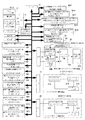
図1はこの発明に係る印刷機のインキ供給量制御装置の一実施の形態(実施の形態1)を示すブロック図である。同図において、10はCPU、11はROM、12はRAM、13はスイッチ群、14は表示器、15はフレキシブルディスク又は磁気カードドライブ(ドライブ装置)、16はプリンタ、17〜20は入出力インターフェイス(I/O)、M1〜M11はメモリ、21はインキツボキー駆動装置、22はインキツボローラ駆動装置、23は呼出し停止用エアシリンダ駆動装置である。スイッチ群13には補正ボタン13−1が設けられている。
【0020】
CPU10は、インターフェイス17を介して与えられる各種入力情報を得て、RAM12にアクセスしながら、ROM11に格納されたプログラムに従って動作する。ROM11には各色の印刷ユニット9における刷版7へのインキ供給量を制御するためのプログラム(インキ供給量制御プログラム)が格納されている。なお、このインキ供給量制御プログラムは、例えばCD−ROMなどの記録媒体に記録された状態で提供し、この記録媒体から読み出してハードディスク(図示せず)にインストールするようにしてもよい。
【0021】
インキツボキー駆動装置21はインキツボキー4−1〜4−nに対応して各個に設けられている。すなわち、n個のインキツボキー4(4−1〜4−n)に対し、n個のインキツボキー駆動装置21(21−1〜21−n)が設けられている。これらインキツボキー駆動装置21−1〜21−nによって、インキツボキー4−1〜4−nのインキツボローラ3に対する開き量が各個に調整される。インキツボキー駆動装置21−1〜21−nは、それぞれインキツボキーモータドライバ21Aと、インキツボキーモータ21Bと、ロータリーエンコーダ21Cとを備えている。インキツボキー駆動装置21−1〜21−nは各色のインキツボキー4−1〜4−nに対して設けられている。
【0022】
インキツボローラ駆動装置22は各色のツボローラ3に対応して個別に設けられている。すなわち、4色輪転印刷機において、インキツボローラ駆動装置22は4個のインキツボローラ駆動装置22−1〜22−4から構成され、これらインキツボローラ駆動装置22−1〜22−4によって、各色のインキツボローラ3の送り量が個別に調整される。インキツボローラ駆動装置22−1〜22−4は、それぞれインキツボローラモータドライバ22Aと、インキツボローラモータ22Bと、ロータリーエンコーダ22Cとを備えている。
【0023】
呼出し停止用エアシリンダ駆動装置23は各色のインキ呼出しロール5に対応して個別に設けられている。すなわち、4色輪転印刷機において、呼出し停止用エアシリンダ駆動装置23は4個の呼出し停止用エアシリンダ駆動装置23−1〜23−4から構成され、これら呼出し停止用エアシリンダ駆動装置23−1〜23−4によって、各色のインキ呼出しロール5の呼出し動作が間欠的に停止される。
【0024】
呼出し停止用エアシリンダ駆動装置23−1〜23−4は、それぞれ呼出し停止開始用カウンタ23Aと、呼出しカウンタリセット用カウンタ23Bと、フリップフロップ回路23Cと、呼出し停止用エアシリンダ23Dとを備えている。呼出し停止開始用カウンタ23Aおよび呼出しカウンタリセット用カウンタ23Bには、インキ呼出しカム回転検出用センサ25より、インキ呼出しロール5を往復揺動させる駆動用カムと同軸回転する回転軸の1回転毎に、1パルスの信号が与えられる。
【0025】
メモリM1には、ドライブ装置15にセットされる記録媒体などから読み取られる、各色の印刷ユニット9における版胴8に装着される刷版7の絵柄データが書き込まれる。
メモリM2には、ドライブ装置15にセットされる記録媒体などから読み取られる、各色の印刷ユニット9におけるインキツボローラ3の送り量データRS(RS1〜RS4)が書き込まれる。
メモリM3には、各色ごとの「絵柄面積率−インキツボキー開き量変換カーブ」が格納される。
【0026】
メモリM4には、スイッチ群13におけるオペレータのキー操作によって設定される、各色の印刷ユニット9におけるインキ呼出しロール5の呼出し動作の停止回数W(W1〜W4)が書き込まれる。ここで「呼出し動作の停止回数」とは呼出し動作を停止させる割合を表し、本実施の形態においては、1回の呼出し動作に対する呼出し動作の間引き数または間引く割合であり、たとえば停止回数W=1であれば、1回休んで1回呼出し動作を行う(本来ならば呼出し動作を2回行うところを1回停止する)ことを意味し、停止回数W=2であれば、2回休んで1回呼出し動作(本来ならば呼出し動作を3回行うところを2回停止する)を行うことを意味する。
【0027】
メモリM5には、スイッチ群13におけるオペレータのキー操作によって設定される、各色の印刷ユニット9におけるインキツボキー4−1〜4−nに対しての小絵柄部か否かを判断するためのインキツボキーの開き量に対する所定値が小絵柄部判定値θs(θs1〜θs4)として書き込まれる。
メモリM6には、各色の印刷ユニット9におけるインキツボキー4−1〜4−nに対する開き量の設定値θ1〜θnを後述する処理によって補正した開き量の補正値θ1’〜θn’が書き込まれる。
【0028】
メモリM7には、スイッチ群13におけるオペレータのキー操作によって設定される、各色の印刷ユニット9におけるインキツボキー4−1〜4−nに対しての開き量の補正係数α(α1〜α4)が書き込まれる。なお、補正係数αは、α>0の任意の値として設定される。
【0029】
メモリM8には、オペレータのキー操作によって設定される停止回数Wから求められる、各色の印刷ユニット9における呼出し停止用エアシリンダ駆動装置23における呼出し停止開始用カウンタ23Aに設定する設定値C1(C11 〜C14 )が書き込まれる。
メモリM9には、オペレータのキー操作によって設定される停止回数Wから求められる、各色の印刷ユニット9における呼出し停止用エアシリンダ駆動装置23における呼出しカウンタリセット用カウンタ23Bに設定する設定値C2(C21 〜C24 )が書き込まれる。
【0030】
メモリM10には、スイッチ群13におけるオペレータのキー操作によって設定される、各色の印刷ユニット9におけるインキツボローラ3に対しての送り量の補正係数β(β1〜β4)が書き込まれる。なお、補正係数βは、β>0の任意の値として設定される。
メモリM11には、各色の印刷ユニット9におけるインキツボローラ3の送り量の設定値RS(RS1〜RS4)を後述する処理によって補正した送り量の補正値RS’(RS1’〜RS4’)が書き込まれる。
【0031】
小絵柄部数カウンタ24は各色の版胴8に装着される刷版7の小絵柄部の数をカウントする。この小絵柄部数のカウントについては後述する。
メモリM12には、小絵柄部数カウンタ24によってカウントされた小絵柄部数Km(Km1〜Km4)が書き込まれる。
メモリM13には、インキ呼出し動作の間欠停止を行うか否かの判定を行うための各色の小絵柄部数が小絵柄部数判定値Ks(Ks1〜Ks4)として書き込まれる。
【0032】
〔動作例1:間欠停止+インキツボキーの開き量の補正〕
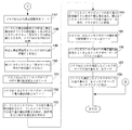
このインキ供給量制御装置における印刷開始前の特徴的な動作(動作例1)を図2および図3に分割して示したフローチャートに従って説明する。印刷ユニット9−1〜9−4のそれぞれにおいて、同様の動作が行われるので、ここでは1つの印刷ユニット9での動作例として説明する。
【0033】
なお、この動作に入る前に、メモリM3には各色ごとの「絵柄面積率−インキツボキー開き量変換カーブ」が格納されているものとする。また、スイッチ群13におけるオペレータのキー操作によって、各色の印刷ユニット9におけるインキツボローラ5に対する呼出し動作の停止回数W(W1〜W4)がメモリM4に、各色の印刷ユニット9におけるインキツボキー4−1〜4−nに対しての小絵柄部判定値θs(θs1〜θs4)がメモリM5に、各色の印刷ユニット9におけるインキツボキー4−1〜4−nに対しての開き量の補正係数α(α1〜α4)がメモリM7に、インキ呼出し動作の間欠停止を行うか否かの判定を行うための各色の小絵柄部数が小絵柄部数判定値Ks(Ks1〜Ks4)としてメモリM13に書き込まれているものとする。
【0034】
〔絵柄データ、送り量データの読み取り、記憶〕
CPU10は、ドライブ装置15にセットされる記録媒体などから印刷ユニット9の版胴8に装着される刷版7の絵柄データ、および印刷ユニット9のインキツボローラ3の送り量データRSを読み取り、絵柄データをインキツボキー4−1〜4−nに対する開き量の設定値としてメモリM1に、送り量データRSをインキツボローラ3に対する送り量の設定値としてメモリM2に書き込む(ステップ101,102)。
【0035】
絵柄データとしては、印刷ユニット9におけるインキツボキー4−1〜4−nに対応する刷版7の各エリアの絵柄面積率データS1〜Snが入力されることもあるし、インキツボキー4−1〜4−nに対応する刷版7の各エリアの絵柄面積率をインキツボキー4−1〜4−nの開き量に変換したインキツボキー開き量データθ1〜θnが入力されることもある。
【0036】
入力された絵柄データが絵柄面積率データであった場合(ステップ103のYES)、CPU10は、メモリM3に格納されている印刷ユニット9用の「絵柄面積率−インキツボキー開き量変換カーブ」を読み出し(ステップ104)、この読み出した「絵柄面積率−インキツボキー開き量変換カーブ」を用いて絵柄面積率データS1〜Snをインキツボキー開き量θ1〜θnに変換し、メモリM1に格納し直す(ステップ105)。入力された絵柄データがインキツボキー開き量データであった場合(ステップ103のNO)、CPU10は、ステップ104,105を経ずに、直ちにステップ106へ進む。これにより、メモリM1には、インキツボキー4−1〜4−nの開き量θ1〜θnが設定値として書き込まれることになる。
【0037】
〔インキ呼出し動作の間欠停止の必要性判断〕
続いて、CPU10は、インキ呼出し動作の間欠停止を行うか否かを次のようにして判断する。ステップ106において、CPU10は、スイッチ群13における自動設定スイッチ13−1のオンを待つ。オペレータによって自動設定スイッチ13−1がオンとされると(ステップ106のYES)、CPU10は、小絵柄部カウンタ24のカウント値を零にリセットする(ステップ107)。
【0038】
そして、メモリM1から最初のインキツボキーの開き量の設定値θ1を読み出す(ステップ108)。また、メモリM5から小絵柄部判定値θsを読み出す(ステップ109)。そして、インキツボキーの開き量の設定値θ1と小絵柄部判定値θsとを比較し(ステップ110)、θ1<θsであれば、小絵柄部数カウンタ24のカウント値を1アップする(ステップ111)。θ1≧θsであれば、直ちにステップ112へ進む。
【0039】
すなわち、CPU10は、θ1<θsであれば(ステップ110のYES)、インキツボキー4−1に対応する刷版7のエリアは小絵柄部であると判断し、小絵柄部数カウンタ24のカウント値を1アップする。これに対し、θ1≧θsであれば(ステップ110のNO)、インキツボキー4−1に対応する刷版7のエリアは大中絵柄部であると判断し、小絵柄部数カウンタ24のカウント値はアップせずに、直ちにステップ112へ進む。
【0040】
ステップ112において、CPU10は、メモリM1から次のインキツボキーの開き量の設定値θ2を読み出す。また、メモリM5から小絵柄部判定値θsを読み出す(ステップ113)。そして、インキツボキーの開き量の設定値θ2と小絵柄部判定値θsとを比較し(ステップ114)、θ2<θsであれば、先のステップ111と同様にして小絵柄部であると判断し、小絵柄部数カウンタ24のカウント値を1アップする(ステップ115)。θ1≧θsであれば、大中絵柄部であると判断し、直ちにステップ116へ進む。
【0041】
以下同様にして、CPU10は、ステップ116においてメモリM1からの全てのインキツボキーの開き量の設定値θの読み出しが確認されるまで、ステップ112〜115の動作を繰り返す。これにより、小絵柄部数カウンタ24は、インキツボキー4−1〜4−nのうち、その開き量の設定値θがθs以下の小絵柄部と判断されたインキツボキーの数(小絵柄部数)をカウントすることになる。
【0042】
CPU10は、この小絵柄部数カウンタ24によってカウントされた小絵柄部数KmをメモリM12に書き込み(ステップ117)、メモリM13から小絵柄部数判定値Ksを読み出し(ステップ118)、小絵柄部数Kmと小絵柄部数判定値Ksとを比較する(ステップ119)。
【0043】
Km≦Ksであれば(ステップ119のYES)、CPU10は、印刷ユニット9の版胴8にセットされている刷版7は小絵柄部の数が少なく、インキ呼出し動作の間欠停止は不要であると判断する。
【0044】
この場合、CPU10は、メモリM1からインキツボキーの開き量の設定値θ1〜θnを読み出し(ステップ120)、この読み出したインキツボキーの開き量の設定値θ1〜θnをインキツボキー駆動装置21のインキツボキーモータドライバ21Aへ送り(ステップ121)、印刷時におけるインキツボキー4−1〜4−nの開き量をθ1〜θnに合わせ込むようにする。
【0045】
また、メモリM2からインキツボローラの送り量の設定値RSを読み出し(ステップ122)、この読み出したインキツボローラの送り量の設定値RSをインキツボローラ駆動装置22のインキツボローラモータドライバ22Aへ送り(ステップ123)、インキツボローラ3の送り量をRSに合わせ込む。
【0046】
このようにして、CPU10は、小絵柄部の数が少ないと判断した場合、インキツボキー4−1〜4−nの開き量を通常の設定値θ1〜θnに合わせ込み、また印刷時におけるインキツボローラ3の送り量を通常の設定値RSに合わせ込むようにし、一連の処理を終了する。
【0047】
これに対して、Km>Ksである場合(ステップ119のNO)、CPU10は、印刷ユニット9の版胴8にセットされている刷版7は小絵柄部の数が多く、インキ呼出し動作の間欠停止が必要であると判断する。
【0048】
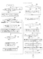
この場合、CPU10は、メモリM4から停止回数Wを読み出し(ステップ124:図3)、この停止回数Wより呼出し停止用エアシリンダ駆動装置23における呼出し停止開始用カウンタ23Aへの設定値C1および呼出しカウンタリセット用カウンタ23Bへの設定値C2を求め、それぞれメモリM8およびM9に書き込む(ステップ125)。また、設定値C1を呼出し停止開始用カウンタ23Aへ、設定値C2を呼出しカウンタリセット用カウンタ23Bへ送り、セットする(ステップ126、127)。
【0049】
例えば、停止回数Wが1回であった場合、本来ならば呼出し動作を2回行うところを1回停止すると判断し、呼出し停止開始用カウンタ23Aへの設定値C1をC1=1、呼出しカウンタリセット用カウンタ23Bへの設定値C2をC2=2とする。この呼出し停止開始用カウンタ23Aおよび呼出しカウンタリセット用カウンタ23Bへの設定値C1,C2のセットにより、印刷ユニット9におけるインキ呼出しロール5のインキ呼出し動作の間欠停止の準備が整う。ここで、実際に印刷することも可能である。
【0050】
〔インキ呼出し動作の間欠停止〕
印刷ユニット9におけるインキ呼出し動作の間欠停止について、停止回数Wが1回である場合を例にとって説明しておく。印刷機の運転が開始されると、呼出し停止開始用カウンタ23Aおよび呼出しカウンタリセット用カウンタ23Bには、印刷機の回転に同調してインキ呼出しロール5を往復揺動させる駆動用カムと同軸回転する回転軸の1回転毎に、インキ呼出しカム回転検出用センサ25より1パルスの信号(センサ信号)が与えられる。
【0051】
呼出し停止開始用カウンタ23Aは、このセンサ信号をC1回(この例では、1回)カウントすると、フリップフロップ回路23CのS入力に「H」レベルを出力してフリップフロップ回路23Cをセット状態とし、そのQ出力を「H」レベルとする。このフリップフロップ回路23Cからの「H」レベルのQ出力を受けて、呼出し停止用エアシリンダ23Dが作動し、インキ呼出しロール5をインキローラ6−1側に押し付け、インキ呼出し動作を停止させる。インキ呼出し動作の停止状態であっても、インキ呼出しロール5を往復揺動させる駆動用カムと同軸回転する回転軸は回転を続けるので、呼出し停止開始用カウンタ23Aおよび呼出しカウンタリセット用カウンタ23Bへのセンサ信号は入力され続ける。
【0052】
呼出しカウンタリセット用カウンタ23Bは、センサ信号をC2回(この例では、2回)カウントすると、フリップフロップ回路23Cをリセット状態とし、そのQ出力を「L」レベルとする。これにより、呼出し停止用エアシリンダ23Dが非作動状態に戻り、インキ呼出し動作が再開される。また、呼出しカウンタリセット用カウンタ23Bは、センサ信号をC2回カウントすると、自己のカウント値および呼出し停止開始用カウンタ23Aのカウント値を零に戻し、次のセンサ信号の入力に備える。このようにして、停止回数Wが1回とされた場合、1回休んで1回呼出し動作を行うというように、インキ呼出し動作が間欠的に停止される。
【0053】
〔インキツボキーの開き量の補正〕
次に、CPU10は、メモリM1から最初のインキツボキーの開き量の設定値θ1を読み出す(ステップ128)。また、メモリM5から小絵柄部判定値θsを読み出す(ステップ129)。そして、この読み出したインキツボキーの開き量の設定値θ1と小絵柄部判定値θsとを比較し(ステップ130)、θ1<θsであればステップ131へ進み、θ1≧θsであればステップ132へ進む。
【0054】
すなわち、θ1<θsであれば(ステップ130のNO)、インキツボキー4−1に対応する刷版7のエリアは小絵柄部であると判断し、メモリM1から読み出したインキツボキーの開き量の設定値θ1をそのままθ1’としてメモリM6に書き込む(ステップ131)。
【0055】
これに対し、θ1≧θsであれば(ステップ130のYES)、インキツボキー4−1に対応する刷版7のエリアは大中絵柄部であると判断し、メモリM7から補正係数αを読み出し(ステップ132)、この補正係数αをメモリM1から読み出したインキツボキーの開き量の設定値θ1に掛け、設定値θ1に対する補正量を求める(ステップ133)。
【0056】
そして、この補正量を設定値θ1に加え、インキツボキーの開き量の補正値θ1’を求め、メモリM6に書き込む(ステップ134)。これにより、対応するエリアが大中絵柄部であると判断されたインキツボキー4−1に対する開き量の設定値θ1は、その設定値θ1に補正係数αを掛けた値だけ大きくなるように補正される。
【0057】
次に、CPU10は、メモリM1から次のインキツボキーの開き量の設定値θ2を読み出す(ステップ135)。また、メモリM5から小絵柄部判定値θsを読み出す(ステップ136)。そして、インキツボキーの開き量の設定値θ2と小絵柄部判定値θsとを比較し(ステップ137)、θ2<θsであれば、先のステップ131と同様にして、設定値θ2をそのままθ2’としてメモリM6に書き込む(ステップ138)。
【0058】
θ2≧θsであれば、先のステップ132〜134と同様にして、メモリM7から補正係数αを読み出し(ステップ139)、この補正係数αを設定値θ2に掛けて補正量を求め(ステップ140)、設定値θ2にこの補正量を加えた値をθ2’としてメモリM6に書き込む(ステップ141)。
【0059】
以下同様にして、CPU10は、ステップ142においてメモリM1からの全てのインキツボキーの開き量の設定値θの読み出しが確認されるまで、ステップ135〜141の動作を繰り返す。これにより、メモリM6には、インキツボキーの開き量の補正値θ1’〜θn’が格納される。
【0060】
ここで、メモリM6に格納されたインキツボキーの開き量の補正値θ1’〜θn’は、設定値θが小絵柄部判定値θsよりも小さいものについては実質的には補正されておらず、設定値θが小絵柄部判定値θsよりも大きいものだけが補正されている。すなわち、インキツボキー4−1〜4−nに対するインキツボキーの開き量の設定値θ1〜θnは、その対応するエリアが小絵柄部(θ<θs)のものについては補正されないが、大中絵柄部(θ≧θs)のものについてのみ補正されて大きくなる。
【0061】
以上のように、この動作例1では、インキツボキーの開き量の設定値θに基づいて、各インキツボキーに対応するエリアが小絵柄部か否かを判定し、小絵柄部でないものについてインキツボキーの開き量を補正する。
【0062】
メモリM6へのインキツボキーの開き量の補正値θ1’〜θn’の格納が完了すると(ステップ142のYES)、CPU10は、メモリM6からインキツボキーの開き量の補正値θ1’〜θn’を読み出し(ステップ143)、この読み出したインキツボキーの開き量の補正値θ1’〜θn’をインキツボキー駆動装置21のインキツボキーモータドライバ21Aへ送る(ステップ144)。これにより、インキツボキーモータ21Bが駆動され、印刷ユニット9におけるインキツボキー4−1〜4−nの開き量がθ1’〜θn’に合わせ込まれる。
【0063】
また、CPU10は、メモリM2からインキツボローラの送り量の設定値RSを読み出し(ステップ145)、この読み出したインキツボローラの送り量の設定値RSをインキツボローラ駆動装置22のインキツボローラモータドライバ22Aへ送る(ステップ146)。これにより、印刷時、印刷ユニット9におけるインキツボローラ3の送り量がRSに合わせ込まれるようになる。
【0064】
この動作例1では、インキ呼出し動作を間欠停止させるか否かが小絵柄部の数により自動的に判断されるので、インキ呼出し回数の間引き運転をしなければならないのに間引き運転しなかったり、通常の状態で運転しなければならないのに間引き運転してしまったりという、オペレータの経験不足などから来る不具合が生じず、正常な印刷物が得られるようになる。また、損紙が多く発生する、余分な時間がかかる、オペレータに負担がかかる、印刷資材が無駄になる、作業効率が悪くなる等の問題も解消される。
【0065】
さらに、この動作例1では、インキ呼出し動作の間欠停止が行われる場合、インキツボキー4−1〜4−nに対するインキツボキーの開き量の設定値θ1〜θnのうち、小絵柄部を除く大中絵柄部の設定値だけが大きくなるように補正される。これにより、大中絵柄部へのインキの供給量が増大し、小絵柄部でのインキの過剰供給と大中絵柄部でのインキ供給量の不足とが同時に解消され、オペレータが試刷りを繰り返しながらインキツボキーの開き量やインキローラの送り量を調整するという必要がなくなる。
【0066】
〔動作例2:間欠停止+インキツボローラの送り量の補正〕
上述した動作例1では、インキ呼出し動作を間欠的に停止させる場合、インキツボキーの開き量の設定値θ1〜θnを絵柄面積率に応じて補正するようにしたが、インキツボローラ3の送り量の設定値RSを絵柄面積率に応じて補正するようにしてもよい。
【0067】
以下に説明する動作例2では、インキツボローラ3の送り量の設定値RSを大きくなるように補正することによって、インキツボキーの開き量が小さい小絵柄部へのインキの供給量の増大に比べ、インキツボキーの開き量が大きい大中絵柄部へのインキの供給量をより大きく増大させる。
【0068】
図4にインキツボローラの送り量を調整することによる絵柄面積率(横軸)と印刷濃度(縦軸)との関係を示す。インキツボローラの送り量を調整することによってその特性は変化する。同図に示す特性Iのように、印刷濃度値が絵柄面積率に拘わらず一定値Aである状態から、インキツボローラの送り量を増加すると、濃度値は上昇する。この場合、特性IIに示すように、絵柄面積率の小さい部分ではインキツボローラの送り量の増加に対する印刷濃度値の上昇が鈍く、絵柄面積率が大きくなるにつれて印刷濃度値が徐々に上昇し、ある絵柄面積率に達すると印刷濃度値は略一定となる。このことから、インキツボローラに対する送り量を大きくすると、大中絵柄部へのインキの供給量が増大することが分かる。
【0069】
次に動作例2における動作手順について説明する。図5はこの動作例2の要部を示すフローチャートである。このフローチャートは、図2に示したフローチャートのステップ119でNOと判断された後の処理に続くもので、ステップ119までは動作例1の場合と同じであるので、その説明は省略する。なお、この動作に入る前に、スイッチ群13におけるオペレータのキー操作によって、各色の印刷ユニット9におけるインキツボローラ3に対しての送り量の補正係数β(β1〜β4)がメモリM10に書き込まれているものとする。
【0070】
Km>Ksであることが確認された場合(図2:ステップ119のNO)、CPU10は、印刷ユニット9−1の版胴8にセットされている刷版7は小絵柄部の数が多く、インキ呼出し動作の間欠停止が必要であると判断する。
【0071】
この場合、CPU10は、メモリM4から停止回数Wを読み出し(ステップ147)、この停止回数Wより呼出し停止用エアシリンダ駆動装置23における呼出し停止開始用カウンタ23Aへの設定値C1および呼出しカウンタリセット用カウンタ23Bへの設定値C2を求め、それぞれメモリM8およびM9に書き込む(ステップ148)。また、設定値C1を呼出し停止開始用カウンタ23Aへ、設定値C2を呼出しカウンタリセット用カウンタ23Bへ送り、セットする(ステップ149、150)。
【0072】
次に、CPU10は、メモリM2からインキツボローラの送り量の設定値RSを読み出す(ステップ151)。また、メモリM10から補正係数βを読み出し(ステップ152)、この補正係数βをメモリM2から読み出したインキツボローラの送り量の設定値RSに掛け、設定値RSに対する補正量を求める(ステップ153)。そして、この補正量をメモリM2から読み出したインキツボローラの送り量の設定値RSに加え、インキツボローラの送り量の補正値RS’(RS’=(1+β)・RS)を求め、メモリM11に書き込む(ステップ154)。これにより、インキツボローラ3に対する送り量の設定値RSは、その設定値RSに補正係数βを掛けた値だけ大きくなるように補正される。
【0073】
次に、CPU10は、メモリM1からインキツボキーの開き量の設定値θ1〜θnを読み出し(ステップ155)、この読み出したインキツボキーの開き量の設定値θ1〜θnをインキツボキー駆動装置21のインキツボキーモータドライバ21Aへ送る(ステップ156)。これにより、インキツボキーモータ21Bが駆動され、印刷ユニット9におけるインキツボキー4−1〜4−nの開き量がθ1〜θnに合わせ込まれる。
【0074】
また、CPU10は、メモリM11からインキツボローラの送り量の補正値RS’を読み出し(ステップ157)、この読み出したインキツボローラの送り量の補正値RS’をインキツボローラ駆動装置22のインキツボローラモータドライバ22Aへ送る(ステップ158)。これにより、印刷時、印刷ユニット9におけるインキツボローラ3の送り量がRS’に合わせ込まれるようになる。
【0075】
この動作例2では、インキ呼出し動作を間欠停止させるか否かが小絵柄部の数により自動的に判断される点では動作例1と同じであるが、インキ呼出し動作の間欠停止が行われる場合、インキツボローラ3に対する送り量の設定値RSが大きくなるように補正される。これにより、小絵柄部へのインキの供給量の増大に比べ、大中絵柄部へのインキの供給量がより大きく増大し、小絵柄部でのインキの過剰供給と大中絵柄部でのインキ供給量の不足とが同時に解消され、オペレータが試刷りを繰り返しながらインキツボキーの開き量やインキローラの送り量を調整するという必要がなくなる。
【0076】
〔実施の形態2:自動方式▲2▼〕
次に、実施の形態2として、「間欠停止+補正」をCPU10の判断によって自動で行う第2番目の方式(自動方式▲2▼)について説明する。
【0077】
図6はこの実施の形態2に係るインキ供給量制御装置を示すブロック図である。同図において、図1と同一符号は同一或いは同等構成要素を示し、その説明は省略する。この実施の形態2では、実施の形態1の小絵柄部判定値用メモリM13に代えて、各印刷ユニットの全インキツボキーの数を記憶するメモリM14と、各印刷ユニットの全インキツボキーの数に占める小絵柄部の割合に対する判定値を記憶するメモリM15と、各印刷ユニットの全インキツボキーの数に占める小絵柄部の割合を記憶するメモリM16とを設けている。
【0078】
〔動作例1:間欠停止+インキツボキーの開き量の補正〕
このインキ供給量制御装置における印刷開始前の特徴的な動作(動作例1)を図7および図8に分割して示したフローチャートに従って説明する。印刷ユニット9−1〜9−4のそれぞれにおいて、同様の動作が行われるので、ここでは1つの印刷ユニット9での動作例として説明する。
【0079】
なお、この実施の形態では、各色の印刷ユニット9の全インキツボキーの数Kn(Kn1〜Kn4)がメモリM14に、インキ呼出し動作の間欠停止を行うか否かの判定を行うための各色の小絵柄部の割合(小絵柄部割合判定値)γs(γs1〜γs4)がメモリM15に書き込まれているものとする。
【0080】
図7において、ステップ201〜217までの動作は、図2に示したステップ101〜117までの動作と同じであるので、その説明は省略する。
CPU10は、小絵柄部数KmをメモリM12に書き込むと(ステップ217)、メモリM14に格納されている印刷ユニット9の全インキツボキーの数Knを読み出す(ステップ218)。
【0081】
そして、メモリM12から読み出した小絵柄部数KmとメモリM14から読み出した全インキツボキーの数Knより、印刷ユニット9の全インキツボキーの数に占める小絵柄部の割合γを求め(γ=Km/Kn)、この求めた全インキツボキーの数に占める小絵柄部の割合γをメモリM16に書き込む(ステップ219)。
【0082】
さらに、メモリM15から印刷ユニット9の小絵柄部割合判定値γsを読み出し(ステップ220)、この読み出した小絵柄部割合判定値γsと先のステップ219で求めた全インキツボキーの数に占める小絵柄部の割合γとを比較する(ステップ221)。
【0083】
γ<γsであれば(ステップ221のYES)、CPU10は、印刷ユニット9の版胴8にセットされている刷版7は小絵柄部の数が少なく、インキ呼出し動作の間欠停止は不要であると判断する。この場合、図2に示したステップ120〜123に対応するステップ222〜225の処理動作により、インキツボキー4−1〜4−nの開き量を通常の設定値θ1〜θnに合わせ込み、また印刷時におけるインキツボローラ3の送り量を通常の設定値RSに合わせ込むようにし、一連の処理を終了する。
【0084】
これに対して、γ≧γsであった場合(ステップ221のNO)、CPU10は、印刷ユニット9の版胴8にセットされている刷版7は小絵柄部の数が多く、インキ呼出し動作の間欠停止が必要であると判断する。
この場合、CPU10は、図3に示したステップ124〜146に対応するステップ226〜248(図8)の処理動作により、インキツボキー4−1〜4−nの開き量を補正値θ1’〜θn’に合わせ込む。
【0085】
この動作例1では、インキ呼出し動作を間欠停止させるか否かが小絵柄部の割合により自動的に判断され、この判断に基づいてCPU10からインキ呼出し動作の間欠停止が指示されると、インキツボキー4−1〜4−nに対するインキツボキーの開き量の設定値θ1〜θnのうち、小絵柄部を除く大中絵柄部の設定値だけが大きくなるように補正される。これにより、大中絵柄部へのインキの供給量が増大し、小絵柄部でのインキの過剰供給と大中絵柄部でのインキ供給量の不足とが同時に解消される。
【0086】
この動作例1では、インキ呼出し動作を間欠停止させるか否かが小絵柄部の割合により自動的に判断されるので、インキ呼出し回数の間引き運転をしなければならないのに間引き運転しなかったり、通常の状態で運転しなければならないのに間引き運転してしまったりという、オペレータの経験不足などから来る不具合が生じず、正常な印刷物が得られるようになる。また、損紙が多く発生する、余分な時間がかかる、オペレータに負担がかかる、印刷資材が無駄になる、作業効率が悪くなる等の問題も解消される。
【0087】
さらに、この動作例1では、インキ呼出し動作の間欠停止が行われる場合、インキツボキー4−1〜4−nに対するインキツボキーの開き量の設定値θ1〜θnのうち、小絵柄部を除く大中絵柄部の設定値だけが大きくなるように補正される。これにより、大中絵柄部へのインキの供給量が増大し、小絵柄部でのインキの過剰供給と大中絵柄部でのインキ供給量の不足とが同時に解消され、オペレータが試刷りを繰り返しながらインキツボキーの開き量やインキローラの送り量を調整するという必要がなくなる。
【0088】
〔動作例2:間欠停止+インキツボローラの送り量の補正〕
上述した動作例1では、インキ呼出し動作を間欠的に停止させる場合、インキツボキーの開き量の設定値θ1〜θnを絵柄面積率に応じて補正するようにしたが、インキツボローラ3の送り量の設定値RSを絵柄面積率に応じて補正するようにしてもよい。
【0089】
すなわち、図7のステップ221においてγ≧γsと判断された場合、図9に示すステップ249〜260の処理動作(図5に示したステップ147〜158に対応する処理動作)を実行することによって、インキツボローラ3の送り量を補正値RS’に合わせ込むようにしてもよい。
【0090】
この動作例2では、インキ呼出し動作を間欠停止させるか否かが小絵柄部の割合により自動的に判断される点では動作例1と同じであるが、インキ呼出し動作の間欠停止が行われる場合、インキツボローラ3に対する送り量の設定値RSが大きくなるように補正される。これにより、小絵柄部へのインキの供給量の増大に比べ、大中絵柄部へのインキの供給量がより大きく増大し、小絵柄部でのインキの過剰供給と大中絵柄部でのインキ供給量の不足とが同時に解消され、オペレータが試刷りを繰り返しながらインキツボキーの開き量やインキローラの送り量を調整するという必要がなくなる。
【0091】
なお、上述した実施の形態1では、小絵柄部判定値θsを定め、この小絵柄部判定値θsよりも小さいインキツボキーの数を小絵柄部数Kmとしてカウントするようにしたが、すなわちインキツボキーの開き量の設定値θ1〜θnのうちθ<θsの数を小絵柄部数Kmとしてカウントするようにしたが、零よりも大きくθsよりも小さい(0<θ<θs)インキツボキーの数を小絵柄部数Kmとしてカウントするようにしてもよい。インキツボキーの開き量の設定値θ1〜θnから零を除くことにより、両端の開き量が0%とされるインキツボキーや印刷されない部分のインキツボキーが除外され、実際に印刷される小絵柄部のみが小絵柄部数としてカウントされるようになる。
【0092】
〔実施の形態3〕
また、上述した実施の形態2では、印刷ユニット9における全インキツボキーの数Knに対する小絵柄部数Kmの割合としてγを求めるようにしたが、全インキツボキーの数Knではなく、印刷に使用するインキツボキーの数Kxに対する小絵柄部数Kmの割合としてγを求めるようにしてもよい。印刷に使用するインキツボキーの数Kxは、例えば下記に示す▲1▼,▲2▼の方法で求める。なお、この▲1▼,▲2▼の方法において、小絵柄部数Kmは、開き量の設定値が零よりも大きく小絵柄部判定値θsよりも小さい(0<θ<θs)インキツボキーの数とする。
【0093】
〔▲1▼プリセット情報として入力される用紙サイズを使用する方法〕
インキツボキーの総数nが偶数の場合、用紙サイズ/インキツボキーの幅/2=aとし、印刷に使用するインキツボキーの数KxをKx=(aの端数を繰り上げ整数とした値)×2として求める。また、インキツボキーの総数nが奇数の場合、〔(用紙サイズ/インキツボキーの幅)−1〕/2=a’とし、印刷に使用するインキツボキーの数KxをKx=(a’の端数を繰り上げ整数とした値)×2+1として求める。
【0094】
〔▲2▼絵柄データを使用する方法〕
印刷に使用するインキツボキーの数KxをKx=(インキツボキーの総数n)−(設定値が0%となっているインキツボキーの数)として求める。
【0095】
〔実施の形態3の具体例〕
図10に上述した絵柄データを使用する方法(方法▲2▼)を採用した場合のインキ供給量制御装置のブロック図を示す。同図において、図6と同一符号は同一或いは同等構成要素を示し、その説明は省略する。この実施の形態3では、実施の形態2の各印刷ユニットの全インキツボキーの数に占める小絵柄部の割合用メモリM15に代えて、各印刷ユニットの印刷に使用するインキツボキーの数に占める小絵柄部の割合用メモリM17と、各印刷ユニットの印刷に使用するインキツボキーの数用のメモリM18と、開き量零のインキツボキーの数用メモリM19とを設けている。また、開き量零のインキツボキー数用のカウンタ26を設けている。
【0096】
〔インキ呼出し動作の間欠停止の必要性の判断〕
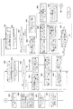
このインキ供給量制御装置におけるインキ呼出し動作の間欠停止を行うか否かの判断動作を図11および図12に分割して示したフローチャートに従って説明する。図11において、ステップ301〜306までの動作は、図7に示したステップ201〜206までの動作と同じであるので、その説明は省略する。
【0097】
オペレータによって自動設定スイッチ13−1がオンとされると(ステップ306のYES)、CPU10は、開き量零のインキツボキー数用のカウンタ26のカウント値を零にリセットする(ステップ307)。そして、メモリM1から最初のインキツボキーの開き量の設定値θ1を読み出す(ステップ308)。そして、インキツボキーの開き量の設定値θ1が零でないか否かをチェックし(ステップ309)、θ1=0であれば、開き量零のインキツボキー数用のカウンタ26のカウント値を1アップする(ステップ310)。θ1≠0であれば、直ちにステップ311へ進む。
【0098】
ステップ311において、CPU10は、メモリM1から次のインキツボキーの開き量の設定値θ2を読み出す。そして、インキツボキーの開き量の設定値θ2が零でないか否かをチェックし(ステップ312)、θ2=0であれば、開き量零のインキツボキー数用のカウンタ26のカウント値を1アップする(ステップ313)。θ1≠0であれば、直ちにステップ314へ進む。
【0099】
以下同様にして、CPU10は、ステップ314においてメモリM1からの全てのインキツボキーの開き量の設定値θの読み出しが確認されるまで、ステップ311〜313の動作を繰り返す。これにより、開き量零のインキツボキー数用のカウンタ26は、インキツボキー4−1〜4−nのうち、その開き量の設定値θが零と判断されたインキツボキーの数をカウントすることになる。CPU10は、この開き量零のインキツボキー数用のカウンタ26によってカウントされた値を開き量零数K0としてメモリM19に書き込む(ステップ315)。
【0100】
次に、CPU10は、メモリM14から印刷ユニット9の全インキツボキーの数Knを読み出し(ステップ316)、この読み出した印刷ユニット9の全インキツボキーの数Knからステップ315で求めた開き量零数K0を差し引いて、印刷に使用するインキツボキーの数Kxを算出する(ステップ317)。そして、この算出したインキツボキーの数KxをメモリM18に書き込む(ステップ318)。
【0101】
そして、CPU10は、小絵柄部数カウンタ24のカウント値を零にリセットし(ステップ319:図12)、メモリM1から最初のインキツボキーの開き量の設定値θ1を読み出す(ステップ320)。また、メモリM5から小絵柄部判定値θsを読み出す(ステップ321)。そして、インキツボキーの開き量の設定値θ1が0<θ1<θsであるか否かをチェックし(ステップ322)、0<θ1<θsであれば、小絵柄部数カウンタ24のカウント値を1アップする(ステップ323)。0<θ1<θsでなければ、直ちにステップ324へ進む。
【0102】
すなわち、CPU10は、0<θ1<θsであれば(ステップ322のYES)、インキツボキー4−1に対応する刷版7のエリアは小絵柄部であると判断し、小絵柄部数カウンタ24のカウント値を1アップする。これに対し、0<θ1<θsでなければ(ステップ322のNO)、インキツボキー4−1に対応する刷版7のエリアは大中絵柄部あるいは印刷に使用されない部分であると判断し、小絵柄部数カウンタ24のカウント値はアップせずに、直ちにステップ324へ進む。
【0103】
ステップ324において、CPU10は、メモリM1から次のインキツボキーの開き量の設定値θ2を読み出す。また、メモリM5から小絵柄部判定値θsを読み出す(ステップ325)。そして、インキツボキーの開き量の設定値θ2が0<θ2<θsであるか否かをチェックし(ステップ326)、0<θ2<θsであれば、小絵柄部数カウンタ24のカウント値を1アップする(ステップ327)。0<θ2<θsでなければ、直ちにステップ328へ進む。
【0104】
以下同様にして、CPU10は、ステップ328においてメモリM1からの全てのインキツボキーの開き量の設定値θの読み出しが確認されるまで、ステップ324〜327の動作を繰り返す。これにより、小絵柄部数カウンタ24は、インキツボキー4−1〜4−nのうち、その開き量の設定値θが0<θ<θsの小絵柄部と判断されたインキツボキーの数(小絵柄部数)をカウントすることになる。CPU10は、この小絵柄部数カウンタ24によってカウントされた小絵柄部数をKmとしてメモリM12に書き込み(ステップ329)、メモリM18から印刷ユニット9の印刷に使用するインキツボキーの数Kxを読み出す(ステップ330)。
【0105】
そして、メモリM12から読み出した小絵柄部数KmとメモリM18から読み出した印刷に使用するインキツボキーの数Kxより、印刷ユニット9の印刷に使用するインキツボキーの数に占める小絵柄部の割合γを求め(γ=Km/Kx)、この求めた印刷に使用するインキツボキーの数に占める小絵柄部の割合γをメモリM16に書き込む(ステップ331)。
【0106】
さらに、メモリM17から印刷ユニット9の小絵柄部割合判定値γsを読み出し(ステップ332)、この読み出した小絵柄部割合判定値γsと先のステップ331で求めた印刷に使用するインキツボキーの数に占める小絵柄部の割合γとを比較する(ステップ333)。
【0107】
γ<γsであれば(ステップ333のYES)、CPU10は、印刷ユニット9の版胴8にセットされている刷版7は小絵柄部の数が少なく、インキ呼出し動作の間欠停止は不要であると判断する。この場合、図7に示したステップ222〜225に対応するステップ334〜337の処理動作により、インキツボキー4−1〜4−nの開き量を通常の設定値θ1〜θnに合わせ込み、また印刷時におけるインキツボローラ3の送り量を通常の設定値RSに合わせ込むようにし、一連の処理を終了する。
【0108】
これに対して、γ≧γsであった場合(ステップ333のNO)、CPU10は、印刷ユニット9の版胴8にセットされている刷版7は小絵柄部の数が多く、インキ呼出し動作の間欠停止が必要であると判断する。この場合、CPU10は、図8に示したステップ226〜248に対応する処理動作(動作例1)により、インキツボキー4−1〜4−nの開き量を補正値θ1’〜θn’に合わせ込む。あるいは、図9に示したステップ249〜260に対応する処理動作(動作例2)により、印刷時におけるインキツボローラ3の送り量を補正値RS’に合わせ込むようにする。
【0109】
〔実施の形態4:自動方式〕
実施の形態1で説明した自動方式では、インキツボキー4の開き量の設定値θを補正したり、インキツボローラ3の送り量の設定値RSを補正するようにした。これに対し、実施の形態4の自動方式では、インキツボキー4の開き量の実際値θpvを補正したり、インキツボローラ3の送り量の実際値RSpvを補正する。また、インキツボキーの開き量の実際値θpvが小絵柄部判定値θsよりも小さいインキツボキーの数をカウントし、このカウントしたインキツボキーの数がKsよりも大きい場合に、インキ呼出し回数の間引き運転が必要であると判断する。図13にこの実施の形態4のインキ供給量制御装置のブロック図を示す。尚、図13においては、図1のインキツボキー駆動装置21のロータリーエンコーダ21Cがポテンショメータ21Dに、インキツボローラ駆動装置22のロータリエンコーダ22Cがタコジェネレータ22Dに置き換えられている。
【0110】
〔動作例1:間欠停止+インキツボキーの開き量の補正〕
このインキ供給量制御装置における印刷開始前の特徴的な動作(動作例1)を図14および図15に分割して示したフローチャートに従って説明する。印刷ユニット9−1〜9−4のそれぞれにおいて、同様の動作が行われるので、ここでは1つの印刷ユニット9での動作例として説明する。
【0111】
〔絵柄データ、送り量データの読み取り、記憶〕
この実施の形態4においても、図2に示したステップ101〜105と対応するステップ601〜605の処理動作によって、メモリM1にインキツボキーの開き量の設定値θ1〜θnを記憶し、メモリM2にインキツボローラの送り量の設定値RSを記憶する。
【0112】
そして、メモリM1からインキツボキーの開き量の設定値θ1〜θnを読み出し(ステップ606)、この読み出したインキツボキーの開き量の設定値θ1〜θnをインキツボキー駆動装置21のインキツボキーモータドライバ21Aへ送る(ステップ607)。これにより、インキツボキーモータ21Bが駆動され、印刷ユニット9におけるインキツボキー4−1〜4−nの開き量がθ1〜θnに合わせ込まれる。
【0113】
また、CPU10は、メモリM2からインキツボローラの送り量の設定値RSを読み出し(ステップ608)、この読み出したインキツボローラの送り量の設定値RSをインキツボローラ駆動装置22のインキツボローラモータドライバ22Aへ送る(ステップ609)。これにより、印刷時、印刷ユニット9におけるインキツボローラ3の送り量がRSに合わせ込まれる。
【0114】
〔インキ呼出し動作の間欠停止の必要性判断〕
続いて、インキ呼出し動作の間欠停止を行うか否かを次のようにして判断する。ステップ610において、CPU10は、スイッチ群13における自動設定スイッチ13−2のオンを待つ。オペレータによって自動設定スイッチ13−2がオンとされると(ステップ610のYES)、CPU10は、小絵柄部カウンタ24のカウント値を零にリセットする(ステップ611)。
【0115】
そして、最初のインキツボキーのポテンショメータ21Dよりインキツボキーの開き量の実際値θ1pvを読み取る(ステップ612)。また、メモリM5から小絵柄部判定値θsを読み出す(ステップ613)。そして、インキツボキーの開き量の実際値θ1pvと小絵柄部判定値θsとを比較し(ステップ614)、θ1pv<θsであれば、小絵柄部数カウンタ24のカウント値を1アップする(ステップ605)。θ1pv≧θsであれば、直ちにステップ616へ進む。
【0116】
すなわち、CPU10は、θ1pv<θsであれば(ステップ614のYES)、インキツボキー4−1に対応する刷版7のエリアは小絵柄部であると判断し、小絵柄部数カウンタ24のカウント値を1アップする。これに対し、θ1pv≧θsであれば(ステップ614のNO)、インキツボキー4−1に対応する刷版7のエリアは大中絵柄部であると判断し、小絵柄部数カウンタ24のカウント値はアップせずに、直ちにステップ616へ進む。
【0117】
ステップ616において、CPU10は、次のインキツボキーのポテンショメータ21Dよりインキツボキーの開き量の実際値θ2pvを読み取る。また、メモリM5から小絵柄部判定値θsを読み出す(ステップ617)。そして、インキツボキーの開き量の実際値θ2pvと小絵柄部判定値θsとを比較し(ステップ618)、θ2pv<θsであれば、先のステップ615と同様にして小絵柄部であると判断し、小絵柄部数カウンタ24のカウント値を1アップする(ステップ619)。θ1pv≧θsであれば、大中絵柄部であると判断し、直ちにステップ620へ進む。
【0118】
以下同様にして、CPU10は、ステップ620において全てのインキツボキーのポテンショメータ21Dよりインキツボキーの開き量の実際値θpvの読み取りが確認されるまで、ステップ616〜620の動作を繰り返す。これにより、小絵柄部数カウンタ24は、インキツボキー4−1〜4−nのうち、その開き量の実際値θpvがθsより小さい小絵柄部と判断されたインキツボキーの数(小絵柄部数)をカウントすることになる。
【0119】
CPU10は、この小絵柄部数カウンタ24によってカウントされた小絵柄部数KmをメモリM12に書き込み(ステップ621)、メモリM13から小絵柄部数判定値Ksを読み出し(ステップ622)、小絵柄部数Kmと小絵柄部数判定値Ksとを比較する(ステップ623)。
【0120】
Km≦Ksであれば(ステップ623のYES)、CPU10は、印刷ユニット9の版胴8にセットされている刷版7は小絵柄部の数が少なく、インキ呼出し動作の間欠停止は不要であると判断し、一連の処理を終了する。
【0121】
これに対して、Km>Ksである場合(ステップ623のNO)、CPU10は、印刷ユニット9の版胴8にセットされている刷版7は小絵柄部の数が多く、インキ呼出し動作の間欠停止が必要であると判断する。
【0122】
この場合、CPU10は、メモリM4から停止回数Wを読み出し(ステップ624:図15)、図3に示したステップ125〜127に対応するステップ625〜627の処理動作によって、呼出し停止用エアシリンダ駆動装置23における呼出し停止開始用カウンタ23Aおよび呼出しカウンタリセット用カウンタ23Bへ設定値C1および設定値C2をセットし、印刷ユニット9におけるインキ呼出しロール5のインキ呼出し動作の間欠停止の準備を整える。
【0123】
〔インキツボキーの開き量の補正〕
次に、CPU10は、最初のインキツボキーのポテンショメータ21Dよりインキツボキーの開き量の実際値θ1pvを読み取る(ステップ628)。また、メモリM5から小絵柄部判定値θsを読み出す(ステップ629)。そして、この読み出したインキツボキーの開き量の実際値θ1pvと小絵柄部判定値θsとを比較し(ステップ630)、θ1pv<θsであればステップ631へ進み、θ1pv≧θsであればステップ632へ進む。
【0124】
すなわち、θ1pv<θsであれば(ステップ630のNO)、インキツボキー4−1に対応する刷版7のエリアは小絵柄部であると判断し、ポテンショメータ21Dより読み取ったインキツボキーの開き量の実際値θ1pvをそのままθ1pv’としてメモリM20に書き込む(ステップ631)。
【0125】
これに対し、θ1pv≧θsであれば(ステップ630のYES)、インキツボキー4−1に対応する刷版7のエリアは大中絵柄部であると判断し、メモリM7から補正係数αを読み出し(ステップ632)、この補正係数αをポテンショメータ21Dより読み取ったインキツボキーの開き量の実際値θ1pvに掛け、実際値θ1pvに対する補正量を求める(ステップ633)。
【0126】
そして、この補正量を実際値θ1pvに加え、インキツボキーの開き量の補正値θ1pv’を求め、メモリM20に書き込む(ステップ634)。これにより、対応するエリアが大中絵柄部であると判断されたインキツボキー4−1に対する開き量の実際値θ1pvは、その実際値θ1pvに補正係数αを掛けた値だけ大きくなるように補正される。
【0127】
次に、CPU10は、次のインキツボキーのポテンショメータ21Dよりインキツボキーの開き量の実際値θ2pvを読み出す(ステップ635)。また、メモリM5から小絵柄部判定値θsを読み出す(ステップ636)。そして、インキツボキーの開き量の実際値θ2pvと小絵柄部判定値θsとを比較し(ステップ637)、θ2pv<θsであれば、先のステップ631と同様にして、実際値θ2pvをそのままθ2pv’としてメモリM20に書き込む(ステップ638)。
【0128】
θ2pv≧θsであれば、先のステップ632〜634と同様にして、メモリM7から補正係数αを読み出し(ステップ639)、この補正係数αを実際値θ2pvに掛けて補正量を求め(ステップ640)、実際値θ2pvにこの補正量を加えた値をθ2pv’としてメモリM20に書き込む(ステップ641)。
【0129】
以下同様にして、CPU10は、ステップ642において全てのインキツボキーのポテンショメータ21Dよりインキツボキーの開き量の実際値θpvの読み取りが確認されるまで、ステップ635〜641の動作を繰り返す。これにより、メモリM20には、インキツボキーの開き量の補正値θ1pv’〜θnpv’が格納される。
【0130】
ここで、メモリM20に格納されたインキツボキーの開き量の補正値θ1pv’〜θnpv’は、実際値θpvが小絵柄部判定値θsよりも小さいものについては実質的には補正されておらず、実際値θpvが小絵柄部判定値θsよりも大きいものだけが補正されている。すなわち、インキツボキー4−1〜4−nの開き量の実際値θ1pv〜θnpvは、その対応するエリアが小絵柄部(θpv<θs)のものについては補正されないが、大中絵柄部(θpv≧θs)のものについてのみ補正されて大きくなる。
【0131】
メモリM20へのインキツボキーの開き量の補正値θ1pv’〜θnpv’の格納が完了すると(ステップ642のYES)、CPU10は、メモリM20からインキツボキーの開き量の補正値θ1pv’〜θnpv’を読み出し(ステップ643)、この読み出したインキツボキーの開き量の補正値θ1pv’〜θnpv’をインキツボキー駆動装置21のインキツボキーモータドライバ21Aへ送る(ステップ644)。これにより、インキツボキーモータ21Bが駆動され、印刷ユニット9におけるインキツボキー4−1〜4−nの開き量がθ1pv’〜θnpv’に合わせ込まれる。
【0132】
〔動作例2:間欠停止+インキツボローラの送り量の補正〕
上述した動作例1では、インキ呼出し動作を間欠的に停止させる場合、インキツボキーの開き量の実際値θ1pv〜θnpvを絵柄面積率に応じて補正するようにしたが、インキツボローラ3の送り量の実際値RSpvを絵柄面積率に応じて補正するようにしてもよい。
【0133】
以下に説明する動作例2では、インキツボローラ3の送り量の実際値RSを大きくなるように補正することによって、インキツボキーの開き量が小さい小絵柄部へのインキの供給量の増大に比べ、インキツボキーの開き量が大きい大中絵柄部へのインキの供給量をより大きく増大させる。
【0134】
図16はこの動作例2の要部を示すフローチャートである。このフローチャートは、図14に示したフローチャートのステップ623でNOと判断された後の処理に続くもので、ステップ623までは動作例1の場合と同じであるので、その説明は省略する。
【0135】
Km>Ksであることが確認された場合(図14:ステップ623のNO)、CPU10は、印刷ユニット9−1の版胴8にセットされている刷版7は小絵柄部の数が多く、インキ呼出し動作の間欠停止が必要であると判断する。
【0136】
この場合、CPU10は、メモリM4から停止回数Wを読み出し(ステップ645)、この停止回数Wより呼出し停止用エアシリンダ駆動装置23における呼出し停止開始用カウンタ23Aへの設定値C1および呼出しカウンタリセット用カウンタ23Bへの設定値C2を求め、それぞれメモリM8およびM9に書き込む(ステップ646)。また、設定値C1を呼出し停止開始用カウンタ23Aへ、設定値C2を呼出しカウンタリセット用カウンタ23Bへ送り、セットする(ステップ647、648)。
【0137】
次に、CPU10は、タコジェネレータ22Dよりインキツボローラの送り量の実際値RSpvを読み取る(ステップ649)。また、メモリM10から補正係数βを読み出し(ステップ650)、この補正係数βをタコジェネレータ22Dより読み取ったインキツボローラの送り量の実際値RSpvに掛け、実際値RSpvに対する補正量を求める(ステップ651)。そして、この補正量をタコジェネレータ22Dより読み取ったインキツボローラの送り量の実際値RSpvに加え、インキツボローラの送り量の補正値RSpv’を求め、メモリM21に書き込む(ステップ652)。これにより、インキツボローラ3の送り量の実際値RSpvは、その実際値RSpvに補正係数βを掛けた値だけ大きくなるように補正される。
【0138】
次に、CPU10は、メモリM21からインキツボローラの送り量の補正値RSpv’を読み出し(ステップ653)、この読み出したインキツボローラの送り量の補正値RSpv’をインキツボローラ駆動装置22のインキツボローラモータドライバ22Aへ送る(ステップ654)。これにより、印刷時、印刷ユニット9におけるインキツボローラ3の送り量がRSpv’に合わせ込まれるようになる。
【0139】
なお、上述した実施の形態1〜4では、インキツボローラ3とインキロール6−1との間にインキ呼出しロール5を設けた例で説明したが、インキツボローラ3からインキ着ロール6−2に至るロール群のいずれかをインキ呼出しロールとし、そのインキ呼出しロールの揺動を間欠的に停止させるようにしたものにも同様にして適用することができる。
【0140】
【発明の効果】
以上説明したことから明らかなように本発明によれば、インキツボキーの開き量が所定の範囲にあるインキツボキーの数をカウントし、このカウントしたインキツボキーの数に基づいてインキ呼出しロール間欠停止手段を作動させるようにしたので、インキ呼出し動作の間欠停止を行うか否かの判断を自動化し、オペレータの負担を軽減することが可能となる。
【図面の簡単な説明】
【図1】 本発明に係る印刷機のインキ供給量制御装置の一実施の形態(実施の形態1)を示すブロック図である。
【図2】 実施の形態1における印刷開始前の特徴的な動作(動作例1,動作例2)を説明するためのフローチャートである。
【図3】 図2に続く実施の形態1の動作例1のフローチャートである。
【図4】 インキツボローラの送り量を調整することによる絵柄面積率と印刷濃度との関係を示す図である。
【図5】 図2に続く実施の形態1の動作例2のフローチャートである。
【図6】 本発明に係る印刷機のインキ供給量制御装置の他の実施の形態(実施の形態2)を示すブロック図である。
【図7】 実施の形態2における印刷開始前の特徴的な動作(動作例1,動作例2)を説明するためのフローチャートである。
【図8】 図7に続く実施の形態2の動作例1のフローチャートである。
【図9】 図7に続く実施の形態2の動作例2のフローチャートである。
【図10】 本発明に係る印刷機のインキ供給量制御装置の別の実施の形態(実施の形態3)の具体例を示すブロック図である。
【図11】 図10に示したインキ供給量制御装置においてインキ呼出し動作の間欠停止を行うか否かの判断動作を説明するためのフローチャートである。
【図12】 図11に続く処理動作のフローチャートである。
【図13】 本発明に係る印刷機のインキ供給量制御装置の別の実施の形態(実施の形態4)を示すブロック図である。
【図14】 実施の形態4における印刷開始前の特徴的な動作(動作例1,動作例2)を説明するためのフローチャートである。
【図15】 図14に続く実施の形態4の動作例1のフローチャートである。
【図16】 図14に続く実施の形態4の動作例2のフローチャートである。
【図17】 輪転印刷機における各色の印刷ユニット内のインキ供給装置(インカー)の要部を示す図である。
【図18】 4色輪転印刷機を示す側面図である。
【符号の説明】
1…インキツボ、2…インキ、3…インキツボローラ、4(4−1〜4−n)…インキツボキー、5…インキ呼出しロール、6…インキローラ群、7…刷版、8…版胴、9(9−1〜9−4)…印刷ユニット、10…CPU,11…ROM,12…RAM,13…スイッチ群、13−1…補正ボタン、13−1…自動設定スイッチ、14…表示器、15…ドライブ装置、16…プリンタ、17〜20…入出カインターフェイス(I/O)、21(21−1〜21−n)…インキツボキー駆動装置、21A…インキツボキーモータドライバ、21B…インキツボキーモータ、21C…ロータリエンコーダ、21D…ポテンショメータ、22(22−1〜22−4)…インキツボローラ駆動装置、22A…インキツボローラモータドライバ、22B…インキツボローラモータ、22C…ロータリエンコーダ、22D…タコジェネレータ、23(23−1〜23−4)…呼出し停止用エアシリンダ駆動装置、23A…呼出し停止開始用カウンタ、23B…呼出しカウンタリセット用カウンタ、23C…フリップフロップ回路、23D…呼出し停止用エアシリンダ、24…小絵柄部カウンタ、25…インキ呼出しカム回転検出用センサ、26…開き量零のインキツボキー数用のカウンタ、M1…絵柄データ記憶用メモリ、M2…インキツボローラの送り量データ用メモリ、M3…絵柄面積率−インキツボキー開き量変換カーブ用メモリ、M4…停止回数用メモリ、M5…小絵柄判定値用メモリ、M6…補正したインキツボキーの開き量用メモリ、M7…インキツボキー開き量補正係数用メモリ、M8…呼出し停止開始用カウンタの設定値用メモリ、M9…呼出しカウンタリセット用カウンタの設定値用メモリ、M10…インキツボローラの送り量補正係数用メモリ、M11…補正したインキツボローラの送り量用メモリ、M12…小絵柄部数カウンタ用メモリ、M13…小絵柄部数判定値用メモリ、M14…各印刷ユニットの全インキツボキーの数用メモリ、M15…各印刷ユニットの全インキツボキーの数に占める小絵柄部の割合判定値用メモリ、M16…小絵柄部の割合用メモリ、M17…各印刷ユニットの印刷に使用するインキツボキーの数に占める小絵柄部の割合判定値用メモリ、M18…各印刷ユニットの印刷に使用するインキツボキーの数用メモリ、M19…開き量零のインキツボキー数用メモリ、M20…補正したインキツボキーの開き量用メモリ、M21…補正したインキツボローラの送り量用メモリ。[0001]
BACKGROUND OF THE INVENTION
The present invention relates to ink supply control for a printing press, and more specifically, by intermittently stopping the swing of an ink call roll (ink call operation), the occurrence of density unevenness in a printed matter with a small number of patterns. The present invention relates to an ink supply amount control method and apparatus for a printing press that can be suppressed.
[0002]
[Prior art]
Conventionally, an ink supply amount in a printing press is controlled by a gap amount between an ink fountain key and an ink fountain roller. FIG. 17 shows a main part of an ink supply device (inker) in a printing unit for each color in a rotary printing press. In the figure, 1 is an ink fountain, 2 is ink stored in the
[0003]
In this printing press, the ink in the
[0004]
The gap amount between the ink fountain keys 4-1 to 4-n and the ink fountain roller 3 (the opening amount of the ink fountain keys 4-1 to 4-n) is determined by each of the printing plates 7 corresponding to the ink fountain keys 4-1 to 4-n. It is set according to the pattern area ratio of the area. For example, the set values of the opening amounts of the ink fountain keys 4-1 to 4-n are obtained in accordance with the preset “pattern area ratio−ink fountain key opening amount conversion curve”, and the ink fountain keys 4-1 to 4-1 match the set values. The opening amount of 4-n is adjusted. The value of the rotation amount (feed amount) of the ink fountain roller 3 is determined in advance. The setting of the opening amount of the ink fountain keys 4-1 to 4-n and the setting of the feeding amount of the ink fountain roller 3 are performed for each color printing unit 9 (9-1 to 9-4).
[0005]
In the ink supply device in the
[0006]
In recent printing presses, the speed of the printing press has made the balance between the ink supply amount to the printing paper and the ink fountain key opening / closing difficult, and it has become difficult to stabilize the ink supply amount. In particular, for a printed matter having a small pattern (small printed matter), ink is excessively supplied into the ink supply device, which causes density unevenness and the like.
[0007]
Therefore, in the ink recalling device shown in
[0008]
[Patent Document 1]
JP-A-5-147200 (page 2-3, FIG. 1, FIG. 5)
[0009]
[Problems to be solved by the invention]
However, in the ink recalling device disclosed in
[0010]
The present invention has been made to solve such a problem, and an object of the present invention is to reduce the burden on the operator by automating the determination of whether or not to intermittently stop the ink calling operation. It is an object of the present invention to provide an ink supply amount control method and apparatus for a printing press.
[0011]
[Means for Solving the Problems]
In order to achieve such an object, the present invention In the above-mentioned printing press, the opening degree of the ink fountain key Counts the number of ink fountain keys in a predetermined range, and the ink call roll intermittent stopping means is operated based on the counted number of ink fountain keys.
[0012]
In this invention, Number of ink fountain keys whose ink fountain key opening is within the specified range For example, the number of ink fountain keys whose actual value detected by a set value or a potentiometer determined according to the pattern area ratio is smaller than a predetermined value is counted, and the number of ink fountain keys counted is larger than the predetermined number, the ink It is determined that the thinning operation is required for the number of calls, and the ink call roll intermittent drive means is operated. That is, the number of small picture parts is counted, and when the number of small picture parts is larger than a predetermined number, the ink calling operation is intermittently stopped.
[0013]
The ink fountain key opening amount is larger than zero and smaller than a predetermined value (0 <opening amount <predetermined value). The number of ink fountain keys is counted. When the counted number of ink fountain keys is larger than the predetermined number, the ink call roll The intermittent drive means may be operated.
[0014]
Also, the ratio of the counted number of ink fountain keys and the total number of ink fountain keys is obtained, and when the obtained ratio is larger than a preset ratio, the ink calling roll intermittent stop means is operated, or the ink fountain key opening amount is Count the number of ink fountain keys greater than zero and smaller than the predetermined value (0 <opening amount <predetermined value), and determine the ratio between the counted number of ink fountain keys and the number of ink fountain keys used for printing. The ink calling roll intermittent stopping means may be operated when the ratio is larger than a preset ratio.
[0015]
When the ink calling operation is intermittently stopped by the ink calling roll intermittent stopping means, the opening amount of the ink fountain key may be corrected. That is, when it is desired to reduce the number of calls of the ink calling roll to suppress the excessive supply of ink in the small pattern portion, the opening amount of the ink fountain key may be corrected.
[0016]
In this case, the ink fountain key opening amount is corrected only for the ink fountain key opening amount larger than a predetermined value. Thereby, the opening degree of the ink fountain key is corrected only for the large and medium pattern portions excluding the small pattern portion. At this time, if the ink fountain key opening amount is corrected so as to increase, the amount of ink supplied to the large / medium pattern portion in one call increases, and the decrease caused by thinning the number of calls can be compensated. . As a method for correcting the opening amount of the ink fountain key, a method of increasing the value by multiplying a predetermined correction coefficient is conceivable.
[0017]
In the above description, when the ink calling operation is stopped intermittently, the opening amount of the ink fountain key is corrected. However, the rotation amount of the ink fountain roller (feed amount of the ink fountain roller) may be corrected. Here, the rotation amount of the ink fountain roller may be a predetermined set value or an actual value detected by a tachometer generator or the like. At this time, if the feed amount of the ink fountain roller is corrected to be large, as will be described later, the ink fountain key opening amount is large compared to the increase in the ink supply amount to the small pattern portion where the ink fountain key opening amount is small. The amount of ink supplied to the medium pattern portion is greatly increased, and the shortage of ink supply to the large and medium pattern portion is resolved. As a method of correcting the feed amount of the ink fountain roller, a method of increasing by a value obtained by multiplying a predetermined correction coefficient is conceivable.
[0018]
DETAILED DESCRIPTION OF THE INVENTION
Hereinafter, the present invention will be described in detail with reference to the drawings.
[Embodiment 1: Automatic method (1)]
First, as the first embodiment, a first method (automatic method {circle around (1)}) in which “intermittent stop + correction” is automatically performed based on the determination of the
[0019]
FIG. 1 is a block diagram showing an embodiment (Embodiment 1) of an ink supply amount control apparatus for a printing press according to the present invention. In the figure, 10 is a CPU, 11 is a ROM, 12 is a RAM, 13 is a switch group, 14 is a display, 15 is a flexible disk or magnetic card drive (drive device), 16 is a printer, and 17 to 20 are input / output interfaces. (I / O), M1 to M11 are memories, 21 is an ink fountain key drive device, 22 is an ink fountain roller drive device, and 23 is a call cylinder air cylinder drive device. The
[0020]
The
[0021]
The ink fountain
[0022]
The ink fountain
[0023]
The call stop air
[0024]
Each of the call stop air cylinder driving devices 23-1 to 23-4 includes a call stop start
[0025]
In the memory M1, picture data of the printing plate 7 mounted on the
In the memory M2, feed amount data RS (RS1 to RS4) of the ink fountain roller 3 in each
The memory M3 stores a “pattern area ratio-ink fountain key opening amount conversion curve” for each color.
[0026]
In the memory M4, the number W (W1 to W4) of stoppages of the call operation of the ink call roll 5 in each
[0027]
In the memory M5, the opening of the ink fountain key for determining whether or not it is a small pattern portion for the ink fountain keys 4-1 to 4-n in the
In the memory M6, opening amount correction values θ1 ′ to θn ′ obtained by correcting the opening amount setting values θ1 to θn for the ink fountain keys 4-1 to 4-n in the
[0028]
In the memory M7, the opening amount correction coefficient α (α1 to α4) for the ink fountain keys 4-1 to 4-n in the
[0029]
In the memory M8, a set value C1 (C1) set in the call stop start
In the memory M9, a set value C2 (C2) set in the call counter reset counter 23B in the call stop air
[0030]
In the memory M10, a feed amount correction coefficient β (β1 to β4) for the ink fountain roller 3 in each
In the memory M11, feed amount correction values RS ′ (RS1 ′ to RS4 ′) obtained by correcting the feed amount setting values RS (RS1 to RS4) of the ink fountain roller 3 in each
[0031]
The small picture number counter 24 counts the number of small picture parts of the printing plate 7 mounted on the
In the memory M12, the small pattern number Km (Km1 to Km4) counted by the small
In the memory M13, the small pattern number of each color for determining whether to intermittently stop the ink calling operation is written as the small pattern number determination value Ks (Ks1 to Ks4).
[0032]
[Operation example 1: intermittent stop + ink fountain key opening correction]
A characteristic operation (operation example 1) before the start of printing in this ink supply amount control apparatus will be described with reference to flowcharts shown in FIG. 2 and FIG. Since the same operation is performed in each of the printing units 9-1 to 9-4, an operation example in one
[0033]
Before entering this operation, it is assumed that the “picture area ratio—ink fountain key opening amount conversion curve” for each color is stored in the memory M3. Further, the number of times W (W1 to W4) of the calling operation for the ink fountain roller 5 in each
[0034]
[Reading and storing pattern data and feed amount data]
The
[0035]
As the pattern data, pattern area ratio data S1 to Sn of each area of the printing plate 7 corresponding to the ink fountain keys 4-1 to 4-n in the
[0036]
When the input pattern data is pattern area ratio data (YES in step 103), the
[0037]
[Necessity determination of intermittent stopping of ink call operation]
Subsequently, the
[0038]
Then, the setting value θ1 of the first ink fountain key opening amount is read from the memory M1 (step 108). Further, the small pattern portion determination value θs is read from the memory M5 (step 109). Then, the setting value θ1 of the ink fountain key opening amount is compared with the small pattern portion determination value θs (step 110). If θ1 <θs, the count value of the small
[0039]
That is, if θ1 <θs (YES in step 110), the
[0040]
In
[0041]
Similarly, the
[0042]
The
[0043]
If Km ≦ Ks (YES in step 119), the
[0044]
In this case, the
[0045]
Further, the ink fountain roller feed amount setting value RS is read from the memory M2 (step 122), and the read ink fountain roller feed amount setting value RS is read to the ink fountain
[0046]
In this way, when the
[0047]
On the other hand, if Km> Ks (NO in step 119), the
[0048]
In this case, the
[0049]
For example, if the stop count W is 1, it is determined that the place where the call operation is performed twice is stopped once, and the set value C1 to the call stop start counter 23A is C1 = 1, the call counter reset The set value C2 for the counter 23B is set to C2 = 2. By setting the set values C1 and C2 to the call stop start counter 23A and the call counter reset counter 23B, preparation for intermittent stop of the ink call operation of the ink call roll 5 in the
[0050]
[Intermittent stop of ink call operation]
The intermittent stop of the ink calling operation in the
[0051]
When the call stop start
[0052]
When the sensor signal is counted C2 times (in this example, twice), the call counter reset counter 23B resets the flip-
[0053]
[Correction of ink fountain key opening]
Next, the
[0054]
That is, if θ1 <θs (NO in step 130), it is determined that the area of the printing plate 7 corresponding to the ink fountain key 4-1 is a small picture portion, and the setting value θ1 of the ink fountain key opening amount read from the memory M1. Is directly written in the memory M6 as θ1 ′ (step 131).
[0055]
On the other hand, if θ1 ≧ θs (YES in step 130), it is determined that the area of the printing plate 7 corresponding to the ink fountain key 4-1 is a large / medium pattern portion, and the correction coefficient α is read from the memory M7 (step). 132), the correction coefficient α is multiplied by the setting value θ1 of the ink fountain key opening amount read from the memory M1 to obtain a correction amount for the setting value θ1 (step 133).
[0056]
Then, this correction amount is added to the set value θ1, and a correction value θ1 ′ of the ink fountain key opening amount is obtained and written in the memory M6 (step 134). As a result, the setting value θ1 of the opening amount for the ink fountain key 4-1 in which the corresponding area is determined to be the large / medium pattern portion is corrected so as to increase by a value obtained by multiplying the setting value θ1 by the correction coefficient α. .
[0057]
Next, the
[0058]
If θ2 ≧ θs, the correction coefficient α is read from the memory M7 (step 139) and the correction amount is obtained by multiplying the correction coefficient α by the set value θ2 (step 140) in the same manner as the
[0059]
Similarly, the
[0060]
Here, the correction values θ1 ′ to θn ′ of the ink fountain key opening amounts stored in the memory M6 are not substantially corrected when the setting value θ is smaller than the small picture portion determination value θs, and are set. Only those whose value θ is larger than the small picture portion determination value θs are corrected. That is, the setting values θ1 to θn of the ink fountain key opening amounts for the ink fountain keys 4-1 to 4-n are not corrected when the corresponding area is the small pattern portion (θ <θs), but the large and medium pattern portions (θ Only those with ≧ θs) are corrected and increased.
[0061]
As described above, in this operation example 1, based on the setting value θ of the ink fountain key opening amount, it is determined whether or not the area corresponding to each ink fountain key is a small pattern portion. Correct.
[0062]
When the storage of the ink fountain key opening correction values θ1 ′ to θn ′ in the memory M6 is completed (YES in Step 142), the
[0063]
Further, the
[0064]
In this operation example 1, since whether or not the ink calling operation is intermittently stopped is automatically determined based on the number of small pattern portions, the thinning operation is not performed even though the thinning operation must be performed. A normal printed matter can be obtained without causing problems such as a lack of experience of the operator, such as a thinning operation although the operation must be performed in a normal state. In addition, problems such as a large amount of waste paper, extra time, a burden on the operator, waste of printing materials, and poor work efficiency are solved.
[0065]
Further, in this operation example 1, when the ink calling operation is intermittently stopped, the large and medium pattern portions excluding the small pattern portion among the set values θ1 to θn of the ink fountain key opening amounts with respect to the ink fountain keys 4-1 to 4-n. Only the set value of is corrected so as to increase. As a result, the amount of ink supplied to the large and medium pattern parts increases, and the excessive supply of ink in the small and large pattern parts and the shortage of ink supply in the large and medium pattern parts are resolved at the same time, and the operator repeats trial printing. However, there is no need to adjust the opening amount of the ink fountain key and the feed amount of the ink roller.
[0066]
[Operation example 2: intermittent stop + ink fountain roller feed amount correction]
In the operation example 1 described above, when the ink calling operation is intermittently stopped, the setting values θ1 to θn of the ink fountain key opening amount are corrected in accordance with the pattern area ratio. The set value RS may be corrected according to the pattern area ratio.
[0067]
In the operation example 2 described below, by correcting the setting value RS of the feed amount of the ink fountain roller 3 to be large, compared to an increase in the amount of ink supplied to the small pattern portion where the ink fountain key opening amount is small, The amount of ink supplied to the large, medium, and large image portions having a large ink fountain key opening amount is further increased.
[0068]
FIG. 4 shows the relationship between the pattern area ratio (horizontal axis) and the printing density (vertical axis) by adjusting the feed amount of the ink fountain roller. The characteristics change by adjusting the feed amount of the ink fountain roller. As shown by the characteristic I shown in the figure, when the feed density of the ink fountain roller is increased from the state where the print density value is a constant value A regardless of the pattern area ratio, the density value increases. In this case, as shown in the characteristic II, the increase in the print density value with respect to the increase in the feed amount of the ink fountain roller is slow in the portion where the pattern area ratio is small, and the print density value gradually increases as the pattern area ratio increases, When a certain pattern area ratio is reached, the print density value becomes substantially constant. From this, it can be seen that when the feed amount to the ink fountain roller is increased, the amount of ink supplied to the large and medium picture portions increases.
[0069]
Next, an operation procedure in the operation example 2 will be described. FIG. 5 is a flowchart showing a main part of the second operation example. This flowchart follows the processing after NO is determined in
[0070]
When it is confirmed that Km> Ks (FIG. 2: NO in step 119), the
[0071]
In this case, the
[0072]
Next, the
[0073]
Next, the
[0074]
Further, the
[0075]
This operation example 2 is the same as the operation example 1 in that whether or not the ink calling operation is intermittently stopped is automatically determined based on the number of small picture portions, but the ink calling operation is intermittently stopped. The feed amount setting value RS for the ink fountain roller 3 is corrected so as to increase. As a result, compared with the increase in the amount of ink supplied to the small pattern part, the amount of ink supplied to the large and medium pattern part is greatly increased, and the excessive supply of ink in the small pattern part and the ink in the large and medium pattern part are increased. The shortage of the supply amount is resolved at the same time, and the operator need not adjust the opening amount of the ink fountain key and the feed amount of the ink roller while repeating the trial printing.
[0076]
[Embodiment 2: Automatic method (2)]
Next, as a second embodiment, a second method (automatic method {circle around (2)}) in which “intermittent stop + correction” is automatically performed based on the determination of the
[0077]
FIG. 6 is a block diagram showing an ink supply amount control apparatus according to the second embodiment. In the figure, the same reference numerals as those in FIG. 1 denote the same or equivalent components, and the description thereof is omitted. In the second embodiment, in place of the small pattern portion determination value memory M13 of the first embodiment, a memory M14 that stores the number of all ink fountain keys of each printing unit, and a small occupying number of all ink fountain keys of each printing unit. A memory M15 that stores a determination value for the ratio of the pattern portion and a memory M16 that stores a ratio of the small pattern portion in the total number of ink fountain keys of each printing unit are provided.
[0078]
[Operation example 1: intermittent stop + ink fountain key opening correction]
A characteristic operation (operation example 1) before the start of printing in the ink supply amount control apparatus will be described with reference to flowcharts shown in FIG. 7 and FIG. Since the same operation is performed in each of the printing units 9-1 to 9-4, an operation example in one
[0079]
In this embodiment, the number Kn (Kn1 to Kn4) of all ink fountain keys of each
[0080]
In FIG. 7, the operations from
When the
[0081]
Then, the ratio γ of the small picture portion in the total number of ink fountain keys of the
[0082]
Further, the small pattern portion ratio determination value γs of the
[0083]
If γ <γs (YES in step 221), the
[0084]
On the other hand, if γ ≧ γs (NO in step 221), the
In this case, the
[0085]
In this operation example 1, whether or not to stop the ink calling operation intermittently is automatically determined based on the ratio of the small picture portion. Based on this determination, when the
[0086]
In this operation example 1, since whether or not to stop the ink calling operation intermittently is automatically determined based on the ratio of the small pattern portion, the thinning operation is not performed even though the thinning operation must be performed. A normal printed matter can be obtained without causing problems such as a lack of experience of the operator, such as a thinning operation although the operation must be performed in a normal state. In addition, problems such as a large amount of waste paper, extra time, a burden on the operator, waste of printing materials, and poor work efficiency are solved.
[0087]
Further, in this operation example 1, when the ink calling operation is intermittently stopped, the large and medium pattern portions excluding the small pattern portion among the set values θ1 to θn of the ink fountain key opening amounts with respect to the ink fountain keys 4-1 to 4-n. Only the set value of is corrected so as to increase. As a result, the amount of ink supplied to the large and medium pattern parts increases, and the excessive supply of ink in the small and large pattern parts and the shortage of ink supply in the large and medium pattern parts are resolved at the same time, and the operator repeats trial printing. However, there is no need to adjust the opening amount of the ink fountain key and the feed amount of the ink roller.
[0088]
[Operation example 2: intermittent stop + ink fountain roller feed amount correction]
In the operation example 1 described above, when the ink calling operation is intermittently stopped, the setting values θ1 to θn of the ink fountain key opening amount are corrected in accordance with the pattern area ratio. The set value RS may be corrected according to the pattern area ratio.
[0089]
That is, when it is determined that γ ≧ γs in
[0090]
This operation example 2 is the same as the operation example 1 in that it is automatically determined based on the ratio of the small picture portion whether or not the ink calling operation is intermittently stopped, but the ink calling operation is intermittently stopped. The feed amount setting value RS for the ink fountain roller 3 is corrected so as to increase. As a result, compared with the increase in the amount of ink supplied to the small pattern part, the amount of ink supplied to the large and medium pattern part is greatly increased, and the excessive supply of ink in the small pattern part and the ink in the large and medium pattern part are increased. The shortage of the supply amount is resolved at the same time, and the operator need not adjust the opening amount of the ink fountain key and the feed amount of the ink roller while repeating the trial printing.
[0091]
In the first embodiment described above, the small pattern portion determination value θs is determined, and the number of ink fountain keys smaller than the small pattern portion determination value θs is counted as the small pattern portion number Km. The number of θ <θs among the set values θ1 to θn is counted as the small picture portion number Km. However, the number of ink fountain keys is larger than zero and smaller than θs (0 <θ <θs). You may make it count. By removing zero from the setting values θ1 to θn of the ink fountain key opening amount, the ink fountain key whose opening amount at both ends is set to 0% and the ink fountain key of the non-printing part are excluded, and only the small pattern portion that is actually printed is a small pattern. It will be counted as the number of copies.
[0092]
[Embodiment 3]
In the second embodiment described above, γ is obtained as a ratio of the number of small pattern portions Km to the number Kn of all ink fountain keys in the
[0093]
[(1) Method of using paper size input as preset information]
When the total number n of the ink fountain keys is an even number, the paper size / the width of the ink fountain key / 2 = a, and the number Kx of the ink fountain keys used for printing is obtained as Kx = (value obtained by setting the fraction of a to a raised integer) × 2. When the total number n of ink fountain keys is an odd number, [(paper size / width of ink fountain key) −1] / 2 = a ′, and the number Kx of ink fountain keys used for printing is Kx = (a ′ is rounded up to an integer. Value) × 2 + 1.
[0094]
[▲ 2 ▼ How to use pattern data]
The number Kx of ink fountain keys used for printing is determined as Kx = (total number of ink fountain keys n) − (number of ink fountain keys with a set value of 0%).
[0095]
[Specific Example of Embodiment 3]
FIG. 10 shows a block diagram of the ink supply amount control apparatus when the above-described method (method (2)) using pattern data is employed. In the figure, the same reference numerals as those in FIG. 6 denote the same or equivalent components, and the description thereof will be omitted. In the third embodiment, instead of the small pattern portion ratio memory M15 in the total number of ink fountain keys of each printing unit of the second embodiment, the small pattern portion occupies the number of ink fountain keys used for printing of each printing unit. Ratio memory M17, a memory M18 for the number of ink fountain keys used for printing of each printing unit, and a memory M19 for the number of ink fountain keys with zero opening. A
[0096]
[Determination of the necessity for intermittent stop of ink call operation]
The operation for determining whether or not to intermittently stop the ink calling operation in the ink supply amount control apparatus will be described with reference to the flowcharts shown in FIGS. In FIG. 11, the operations from
[0097]
When the automatic setting switch 13-1 is turned on by the operator (YES in step 306), the
[0098]
In
[0099]
Similarly, the
[0100]
Next, the
[0101]
Then, the
[0102]
That is, if 0 <θ1 <θs (YES in step 322), the
[0103]
In step 324, the
[0104]
Similarly, the
[0105]
Then, the ratio γ of the small picture portion occupying the number of ink fountain keys used for printing of the
[0106]
Further, the small pattern portion ratio determination value γs of the
[0107]
If γ <γs (YES in step 333), the
[0108]
On the other hand, if γ ≧ γs (NO in step 333), the
[0109]
[Embodiment 4: Automatic method]
In the automatic method described in the first embodiment, the setting value θ of the opening amount of the
[0110]
[Operation example 1: intermittent stop + ink fountain key opening correction]
A characteristic operation (operation example 1) before the start of printing in this ink supply amount control apparatus will be described with reference to flowcharts shown in FIG. 14 and FIG. Since the same operation is performed in each of the printing units 9-1 to 9-4, an operation example in one
[0111]
[Reading and storing pattern data and feed amount data]
Also in the fourth embodiment, the setting values θ1 to θn of the ink fountain key opening amounts are stored in the memory M1 by the processing operations of
[0112]
Then, the ink fountain key opening amount setting values θ1 to θn are read from the memory M1 (step 606), and the read ink fountain key opening amount setting values θ1 to θn are sent to the ink fountain
[0113]
Further, the
[0114]
[Necessity determination of intermittent stopping of ink call operation]
Subsequently, it is determined as follows whether or not the ink calling operation is intermittently stopped. In
[0115]
Then, the actual value θ1pv of the ink fountain key opening amount is read from the potentiometer 21D of the first ink fountain key (step 612). Further, the small pattern portion determination value θs is read from the memory M5 (step 613). Then, the actual value θ1pv of the ink fountain key opening amount is compared with the small pattern portion determination value θs (step 614). If θ1pv <θs, the count value of the small
[0116]
That is, if θ1pv <θs (YES in step 614), the
[0117]
In step 616, the
[0118]
Similarly, the
[0119]
The
[0120]
If Km ≦ Ks (YES in step 623), the
[0121]
On the other hand, if Km> Ks (NO in step 623), the
[0122]
In this case, the
[0123]
[Correction of ink fountain key opening]
Next, the
[0124]
That is, if θ1pv <θs (NO in step 630), it is determined that the area of the printing plate 7 corresponding to the ink fountain key 4-1 is a small pattern portion, and the actual value θ1pv of the ink fountain key opening amount read from the potentiometer 21D. Is directly written in the memory M20 as θ1pv ′ (step 631).
[0125]
On the other hand, if θ1pv ≧ θs (YES in step 630), it is determined that the area of the printing plate 7 corresponding to the ink fountain key 4-1 is a large / medium pattern portion, and the correction coefficient α is read from the memory M7 (step). 632), the correction coefficient α is multiplied by the actual value θ1pv of the ink fountain key opening amount read from the potentiometer 21D, and a correction amount for the actual value θ1pv is obtained (step 633).
[0126]
Then, this correction amount is added to the actual value θ1pv to obtain a correction value θ1pv ′ of the ink fountain key opening amount, which is written in the memory M20 (step 634). Accordingly, the actual value θ1pv of the opening amount with respect to the ink fountain key 4-1 for which it is determined that the corresponding area is the large / medium pattern portion is corrected so as to increase by the value obtained by multiplying the actual value θ1pv by the correction coefficient α. .
[0127]
Next, the
[0128]
If θ2pv ≧ θs, the correction coefficient α is read from the memory M7 (step 639) and the correction amount is obtained by multiplying the actual value θ2pv (step 640) in the same manner as steps 632 to 634. Then, the value obtained by adding this correction amount to the actual value θ2pv is written in the memory M20 as θ2pv ′ (step 641).
[0129]
Similarly, the
[0130]
Here, the correction values θ1pv ′ to θnpv ′ of the ink fountain key opening amounts stored in the memory M20 are not substantially corrected when the actual value θpv is smaller than the small picture portion determination value θs. Only values having a value θpv larger than the small picture portion determination value θs are corrected. That is, the actual opening values θ1pv to θnpv of the ink fountain keys 4-1 to 4-n are not corrected when the corresponding area is the small pattern portion (θpv <θs), but the large and medium pattern portions (θpv ≧ θs). ) Will be corrected only for the ones.
[0131]
When the storage of the ink fountain key opening correction values θ1pv ′ to θnpv ′ in the memory M20 is completed (YES in Step 642), the
[0132]
[Operation example 2: intermittent stop + ink fountain roller feed amount correction]
In the operation example 1 described above, when the ink calling operation is intermittently stopped, the actual values θ1pv to θnpv of the ink fountain key opening amount are corrected according to the pattern area ratio. The actual value RSpv may be corrected according to the pattern area ratio.
[0133]
In the operation example 2 described below, the actual value RS of the feed amount of the ink fountain roller 3 is corrected so as to increase, compared with an increase in the amount of ink supplied to the small pattern portion where the ink fountain key opening amount is small. The amount of ink supplied to the large, medium, and large image portions having a large ink fountain key opening amount is further increased.
[0134]
FIG. 16 is a flowchart showing a main part of the second operation example. This flowchart follows the processing after NO is determined in
[0135]
When it is confirmed that Km> Ks (FIG. 14: NO in step 623), the
[0136]
In this case, the
[0137]
Next, the
[0138]
Next, the
[0139]
In
[0140]
【The invention's effect】
As is clear from the above description, according to the present invention, Ink fountain key opening Counts the number of ink fountain keys in a predetermined range, and the ink calling roll intermittent stopping means is operated based on the counted number of ink fountain keys, so it is determined whether or not to intermittently stop the ink calling operation. It is possible to automate and reduce the burden on the operator.
[Brief description of the drawings]
FIG. 1 is a block diagram showing an embodiment (Embodiment 1) of an ink supply amount control device for a printing press according to the present invention.
FIG. 2 is a flowchart for explaining a characteristic operation (operation example 1 and operation example 2) before starting printing in the first embodiment.
FIG. 3 is a flowchart of an operation example 1 of the first embodiment following FIG. 2;
FIG. 4 is a diagram showing the relationship between the pattern area ratio and the printing density by adjusting the feed amount of the ink fountain roller.
FIG. 5 is a flowchart of an operation example 2 of the first embodiment following FIG. 2;
FIG. 6 is a block diagram showing another embodiment (Embodiment 2) of an ink supply amount control device for a printing press according to the present invention.
FIG. 7 is a flowchart for explaining characteristic operations (operation example 1 and operation example 2) before starting printing in the second embodiment.
FIG. 8 is a flowchart of an operation example 1 of the second embodiment following FIG. 7;
FIG. 9 is a flowchart of an operation example 2 of the second embodiment following FIG. 7;
FIG. 10 is a block diagram showing a specific example of another embodiment (Embodiment 3) of an ink supply amount control device for a printing press according to the present invention.
FIG. 11 is a flowchart for explaining an operation of determining whether or not to intermittently stop the ink calling operation in the ink supply amount control apparatus shown in FIG. 10;
FIG. 12 is a flowchart of the processing operation following FIG.
FIG. 13 is a block diagram showing another embodiment (Embodiment 4) of an ink supply amount control device for a printing press according to the present invention.
FIG. 14 is a flowchart for explaining characteristic operations (operation example 1 and operation example 2) before starting printing in the fourth embodiment.
FIG. 15 is a flowchart of an operation example 1 of the fourth embodiment following FIG. 14;
FIG. 16 is a flowchart of an operation example 2 of the fourth embodiment following FIG.
FIG. 17 is a diagram illustrating a main part of an ink supply device (inker) in a printing unit for each color in a rotary printing press.
FIG. 18 is a side view showing a four-color rotary printing press.
[Explanation of symbols]
DESCRIPTION OF
Claims (28)
前記インキツボキーに対する前記インキツボローラとの間の隙間量が所定の範囲にあるインキツボキーの数をカウントし、
このカウントしたインキツボキーの数に基づいて前記インキ呼出しロール間欠停止手段を作動させる
ことを特徴とする印刷機のインキ供給量制御方法。An ink fountain roller, a plurality of ink fountain keys arranged side by side in the axial direction of the ink fountain roller, an ink calling roll provided in a swingable manner in an ink supply path from the ink fountain roller to the printing plate, and An ink calling roll swinging means for swinging the ink calling roll in synchronization with the rotation of the printing press, an ink calling roll stopping means for stopping the swinging of the ink calling roll, and the ink calling roll stopping means are operated. An ink calling roll intermittent stopping means for intermittently stopping the swinging of the ink calling roll, and is supplied to the ink fountain roller from the gap between the ink fountain key and the ink fountain roller by the rotation of the ink fountain roller. The ink is supplied to the printing plate by the swinging motion of the ink calling roll, The printing press for printing paper by ink to the printing paper,
Count the number of ink fountain keys in which the gap amount between the ink fountain key and the ink fountain roller is within a predetermined range,
An ink supply amount control method for a printing press, wherein the ink calling roll intermittent stop means is operated based on the counted number of ink fountain keys.
前記カウントしたインキツボキーの数が所定数よりも大きい場合に前記インキ呼出しロール間欠停止手段を作動させる
ことを特徴とする印刷機のインキ供給量制御方法。In the ink supply amount control method for a printing press according to claim 1,
An ink supply amount control method for a printing press, wherein the ink call roll intermittent stop means is operated when the counted number of ink fountain keys is larger than a predetermined number.
前記カウントしたインキツボキーの数とインキツボキー全体の数との割合を求め、
この求めた割合が予め設定されている割合よりも大きい場合に前記インキ呼出しロール間欠停止手段を作動させる
ことを特徴とする印刷機のインキ供給量制御方法。In the ink supply amount control method for a printing press according to claim 1,
Obtain the ratio of the counted number of ink fountain keys and the number of ink fountain keys as a whole,
An ink supply amount control method for a printing press, wherein the ink calling roll intermittent stopping means is operated when the obtained ratio is larger than a preset ratio.
零よりも大きく所定値よりも小さい範囲を前記所定の範囲としてカウントしたインキツボキーの数と印刷に使用するインキツボキーの数との割合を求め、
この求めた割合が予め設定されている割合よりも大きい場合に前記インキ呼出しロール間欠停止手段を作動させる
ことを特徴とする印刷機のインキ供給量制御方法。In the ink supply amount control method for a printing press according to claim 1,
Find the ratio between the number of ink fountain keys counted as the predetermined range and the number of ink fountain keys used for printing, which is greater than zero and smaller than the predetermined value,
An ink supply amount control method for a printing press, wherein the ink calling roll intermittent stopping means is operated when the obtained ratio is larger than a preset ratio.
前記インキ呼出しロール間欠停止手段によって前記インキ呼出しロールの揺動を間欠的に停止させる場合、前記インキツボキーに対する前記インキツボローラとの間の隙間量を補正する
ことを特徴とする印刷機のインキ供給量制御方法。In the ink supply amount control method for a printing press according to claim 1,
Ink supply amount of a printing press characterized by correcting a gap amount between the ink fountain key and the ink fountain roller when the ink call roll intermittently stops by the ink call roll intermittent stopping means Control method.
前記インキツボキーに対する前記インキツボローラとの間の隙間量の補正は、前記インキツボキーと前記インキツボローラとの間の隙間量が予め定められている値よりも大きいもののみに対して行う
ことを特徴とする印刷機のインキ供給量制御方法。In the ink supply amount control method for a printing press according to claim 5,
The correction of the gap amount between the ink fountain roller and the ink fountain roller with respect to the ink fountain key is performed only when the gap amount between the ink fountain key and the ink fountain roller is larger than a predetermined value. Ink supply amount control method for a printing press.
前記インキツボキーに対する前記インキツボローラとの間の隙間量の補正は補正後の値が大きくなる
ことを特徴とする印刷機のインキ供給量制御方法。In the ink supply amount control method for a printing press according to claim 6,
An ink supply amount control method for a printing press, characterized in that the corrected value of the gap amount between the ink fountain key and the ink fountain roller is increased.
前記インキツボキーに対する前記インキツボローラとの間の隙間量の補正は予め定められた補正係数を掛けた値だけ補正後の値が大きくなる
ことを特徴とする印刷機のインキ供給量制御方法。In the ink supply amount control method for a printing press according to claim 6,
A method for controlling an ink supply amount of a printing press, wherein the correction of the gap amount between the ink fountain key and the ink fountain roller is increased by a value multiplied by a predetermined correction coefficient.
前記インキ呼出しロール間欠停止手段によって前記インキ呼出しロールの揺動を間欠的に停止させる場合、前記インキツボローラの回転量を補正する
ことを特徴とする印刷機のインキ供給量制御方法。In the ink supply amount control method for a printing press according to claim 1,
An ink supply amount control method for a printing press, wherein when the ink call roll intermittently stops by the ink call roll intermittent stop means, the rotation amount of the ink fountain roller is corrected.
前記インキツボローラの回転量の補正は補正後の値が大きくなる
ことを特徴とする印刷機のインキ供給量制御方法。The ink supply amount control method for a printing press according to claim 9,
A method for controlling an ink supply amount of a printing machine, wherein the correction value of the rotation amount of the ink fountain roller is increased.
前記インキツボローラの回転量の補正は予め定められた補正係数を掛けた値だけ補正後の値が大きくなる
ことを特徴とする印刷機のインキ供給量制御方法。In the ink supply amount control method for a printing press according to claim 9,
The ink supply amount control method for a printing press, wherein the correction value of the rotation amount of the ink fountain roller is increased by a value multiplied by a predetermined correction coefficient.
前記インキツボキーに対する前記インキツボローラとの間の隙間量が所定の範囲にあるインキツボキーの数をカウントするカウント手段と、
このカウント手段によりカウントされたインキツボキーの数に基づいて前記インキ呼出しロール間欠停止手段を作動させる間欠停止作動手段と
を備えたことを特徴とする印刷機のインキ供給量制御装置。An ink fountain roller, a plurality of ink fountain keys arranged side by side in the axial direction of the ink fountain roller, an ink calling roll provided in a swingable manner in an ink supply path from the ink fountain roller to the printing plate, and An ink calling roll swinging means for swinging the ink calling roll in synchronization with the rotation of the printing press, an ink calling roll stopping means for stopping the swinging of the ink calling roll, and the ink calling roll stopping means are operated. An ink calling roll intermittent stopping means for intermittently stopping the swinging of the ink calling roll, and is supplied to the ink fountain roller from the gap between the ink fountain key and the ink fountain roller by the rotation of the ink fountain roller. The ink is supplied to the printing plate by the swinging motion of the ink calling roll, The printing press for printing paper by ink to the printing paper,
A counting means for counting the number of ink fountain keys in which a gap amount between the ink fountain key and the ink fountain roller is within a predetermined range;
An ink supply amount control device for a printing press, comprising: intermittent stop operation means for operating the ink call roll intermittent stop means based on the number of ink fountain keys counted by the counting means.
前記間欠停止作動手段は、前記カウントされたインキツボキーの数が所定数よりも大きい場合に前記インキ呼出しロール間欠停止手段を作動させる
ことを特徴とする印刷機のインキ供給量制御装置。In the ink supply amount control device for a printing press according to claim 12,
The ink supply amount control device for a printing press, wherein the intermittent stop operation means operates the ink calling roll intermittent stop means when the counted number of ink fountain keys is larger than a predetermined number.
前記間欠停止作動手段は、前記カウントされたインキツボキーの数とインキツボキー全体の数との割合を求め、この求めた割合が予め設定されている割合よりも大きい場合に前記インキ呼出しロール間欠停止手段を作動させる
ことを特徴とする印刷機のインキ供給量制御装置。In the ink supply amount control device for a printing press according to claim 12,
The intermittent stop operating means calculates a ratio between the counted number of ink fountain keys and the total number of ink fountain keys, and operates the ink calling roll intermittent stop means when the calculated ratio is larger than a preset ratio. An ink supply amount control device for a printing press.
前記カウント手段は、前記インキツボキーに対する前記インキツボローラとの間の隙間量が零よりも大きく所定値よりも小さい所定の範囲にあるインキツボキーの数をカウントし、
前記間欠停止作動手段は、前記カウントされたインキツボキーの数と印刷に使用するインキツボキーの数との割合を求め、この求めた割合が予め設定されている割合よりも大きい場合に前記インキ呼出しロール間欠停止手段を作動させる
ことを特徴とする印刷機のインキ供給量制御装置。In the ink supply amount control device for a printing press according to claim 12,
The counting means counts the number of ink fountain keys in a predetermined range in which a gap amount between the ink fountain key and the ink fountain roller is larger than zero and smaller than a predetermined value,
The intermittent stop actuating means obtains a ratio between the counted number of ink fountain keys and the number of ink fountain keys used for printing. An ink supply amount control device for a printing press characterized by operating the means.
前記インキ呼出しロール間欠停止手段によって前記インキ呼出しロールの揺動を間欠的に停止させる場合、前記インキツボキーに対する前記インキツボローラとの間の隙間量を補正する補正手段
を備えたことを特徴とする印刷機のインキ供給量制御装置。In the ink supply amount control device for a printing press according to claim 12,
When the ink call roll intermittently stops by the ink call roll intermittent stop means, the printing apparatus is provided with a correction means for correcting a gap amount between the ink fountain key and the ink fountain roller when intermittently stopped. Ink supply amount control device.
前記補正手段は、前記インキツボキーに対する前記インキツボローラとの間の隙間量が予め定められている値よりも大きいもののみに対して行う
ことを特徴とする印刷機のインキ供給量制御装置。In the ink supply amount control device for a printing press according to claim 16,
The ink supply amount control device for a printing press, wherein the correction means is performed only for a case where a gap amount between the ink fountain key and the ink fountain roller is larger than a predetermined value.
前記補正手段による前記インキツボキーに対する前記インキツボローラとの間の隙間量の補正は補正後の値が大きくなる
ことを特徴とする印刷機のインキ供給量制御装置。In the ink supply amount control device for a printing press according to claim 17,
An ink supply amount control device for a printing press, wherein the correction means increases the value after correction of the gap amount between the ink fountain key and the ink fountain roller.
前記補正手段による前記インキツボキーに対する前記インキツボローラとの間の隙間量の補正は予め定められた補正係数を掛けた値だけ補正後の値が大きくなる
ことを特徴とする印刷機のインキ供給量制御装置。In the ink supply amount control device for a printing press according to claim 17,
The correction of the gap amount between the ink fountain key and the ink fountain roller by the correction means increases the value after correction by a value multiplied by a predetermined correction coefficient. apparatus.
前記インキ呼出しロール間欠停止手段によって前記インキ呼出しロールの揺動を間欠的に停止させる場合、前記インキツボローラの回転量を補正する補正手段
を備えたことを特徴とする印刷機のインキ供給量制御装置。In the ink supply amount control device for a printing press according to claim 12,
Ink supply amount control for a printing press, comprising: correction means for correcting the amount of rotation of the ink fountain roller when the ink call roll intermittently stops by the ink call roll intermittent stop means apparatus.
前記補正手段は、前記インキツボローラの回転量を大きくなるように補正する
ことを特徴とする印刷機のインキ供給量制御装置。In the ink supply amount control device for a printing press according to claim 20,
The ink supply amount control device for a printing press, wherein the correction means corrects the rotation amount of the ink fountain roller to be large.
前記補正手段は、前記インキツボローラの回転量を予め定められた補正係数を掛けた値だけ大きくなるように補正する
ことを特徴とする印刷機のインキ供給量制御装置。In the ink supply amount control device for a printing press according to claim 20,
The ink supply amount control apparatus for a printing press, wherein the correction means corrects the rotation amount of the ink fountain roller so as to increase by a value obtained by multiplying a predetermined correction coefficient.
前記インキツボキーに対するインキツボローラとの間の隙間量は、前記刷版の絵柄面積率に応じて補正されることを特徴とする印刷機のインキ供給量制御方法。In the ink supply amount control method for a printing press according to claim 5,
An ink supply amount control method for a printing press, wherein a gap amount between the ink fountain key and the ink fountain roller is corrected in accordance with a pattern area ratio of the printing plate.
前記インキツボローラの回転量は、前記刷版の絵柄面積率に応じて補正されることを特徴とする印刷機のインキ供給量制御方法。In the ink supply amount control method for a printing press according to claim 9,
An ink supply amount control method for a printing press, wherein the rotation amount of the ink fountain roller is corrected according to a pattern area ratio of the printing plate.
前記インキツボキーに対するインキツボローラとの間の隙間量は、前記刷版の絵柄面積率に応じて補正されることを特徴とする印刷機のインキ供給量制御装置。In the ink supply amount control device for a printing press according to claim 16,
An ink supply amount control device for a printing press, wherein a gap amount between the ink fountain key and the ink fountain roller is corrected in accordance with a pattern area ratio of the printing plate.
前記インキツボローラの回転量は、前記刷版の絵柄面積率に応じて補正されることを特徴とする印刷機のインキ供給量制御装置。In the ink supply amount control device for a printing press according to claim 20,
An ink supply amount control device for a printing press, wherein the rotation amount of the ink fountain roller is corrected in accordance with a pattern area ratio of the printing plate.
前記インキツボキーの開き量が所定の範囲にあるインキツボキーの数をカウントし、Count the number of ink fountain keys whose ink fountain key opening amount is in a predetermined range,
このカウントしたインキツボキーの数に基づいて前記インキ呼出しロール間欠停止手段を作動させる Based on the counted number of ink fountain keys, the ink calling roll intermittent stop means is operated.
ことを特徴とする印刷機のインキ供給量制御方法。An ink supply amount control method for a printing press.
前記インキツボキーの開き量が所定の範囲にあるインキツボキーの数をカウントするカウント手段と、A counting means for counting the number of ink fountain keys whose ink fountain key opening amount is within a predetermined range;
このカウント手段によりカウントされたインキツボキーの数に基づいて前記インキ呼出しロール間欠停止手段を作動させる間欠停止作動手段とIntermittent stop operating means for operating the ink calling roll intermittent stop means based on the number of ink fountain keys counted by the counting means;
を備えたことを特徴とする印刷機のインキ供給量制御装置。An ink supply amount control device for a printing press, comprising:
Priority Applications (7)
| Application Number | Priority Date | Filing Date | Title |
|---|---|---|---|
| JP2002376597A JP4040968B2 (en) | 2002-12-26 | 2002-12-26 | Ink supply amount control method and apparatus for printing press |
| US10/736,975 US7028616B2 (en) | 2002-12-26 | 2003-12-15 | Ink supply amount control method and apparatus for printing press |
| EP03090450A EP1433602B1 (en) | 2002-12-26 | 2003-12-20 | Ink supply amount control method and apparatus for printing press |
| AT03090450T ATE322384T1 (en) | 2002-12-26 | 2003-12-20 | METHOD AND DEVICE FOR ADJUSTING THE INK SUPPLY QUANTITY FOR A PRINTING PRESS |
| ES03090450T ES2261876T3 (en) | 2002-12-26 | 2003-12-20 | METHOD AND CONTROL UNIT OF INK SUPPLY QUANTITY FOR A PRINT PRINT. |
| DE60304427T DE60304427T2 (en) | 2002-12-26 | 2003-12-20 | Method and apparatus for adjusting the ink supply amount for a printing press |
| CNB2003101131971A CN1323839C (en) | 2002-12-26 | 2003-12-26 | Method and device for controlling ink supply amount for printer |
Applications Claiming Priority (1)
| Application Number | Priority Date | Filing Date | Title |
|---|---|---|---|
| JP2002376597A JP4040968B2 (en) | 2002-12-26 | 2002-12-26 | Ink supply amount control method and apparatus for printing press |
Publications (3)
| Publication Number | Publication Date |
|---|---|
| JP2004202947A JP2004202947A (en) | 2004-07-22 |
| JP2004202947A5 JP2004202947A5 (en) | 2005-07-07 |
| JP4040968B2 true JP4040968B2 (en) | 2008-01-30 |
Family
ID=32463571
Family Applications (1)
| Application Number | Title | Priority Date | Filing Date |
|---|---|---|---|
| JP2002376597A Expired - Fee Related JP4040968B2 (en) | 2002-12-26 | 2002-12-26 | Ink supply amount control method and apparatus for printing press |
Country Status (7)
| Country | Link |
|---|---|
| US (1) | US7028616B2 (en) |
| EP (1) | EP1433602B1 (en) |
| JP (1) | JP4040968B2 (en) |
| CN (1) | CN1323839C (en) |
| AT (1) | ATE322384T1 (en) |
| DE (1) | DE60304427T2 (en) |
| ES (1) | ES2261876T3 (en) |
Families Citing this family (11)
| Publication number | Priority date | Publication date | Assignee | Title |
|---|---|---|---|---|
| JP4064882B2 (en) * | 2003-07-07 | 2008-03-19 | リョービ株式会社 | Ink quantity control device for printing press |
| JP3976727B2 (en) * | 2003-12-08 | 2007-09-19 | リョービ株式会社 | Ink kneading method of printing machine and printing machine |
| JP2006137096A (en) * | 2004-11-12 | 2006-06-01 | Komori Corp | Method and equipment for regulating ink supply of printing press |
| JP2007152822A (en) * | 2005-12-07 | 2007-06-21 | Komori Corp | Method and device for switching ink carrying passage of ink device in printer |
| JP4698414B2 (en) * | 2005-12-27 | 2011-06-08 | 大日本スクリーン製造株式会社 | Development processing method and printing press |
| JP2007261092A (en) * | 2006-03-28 | 2007-10-11 | Mitsubishi Heavy Ind Ltd | Ink controller, printing machine and printing method |
| JP2008110500A (en) * | 2006-10-30 | 2008-05-15 | Komori Corp | Ink feeding controlling method and ink feeding controlling device |
| US20080127846A1 (en) * | 2006-11-02 | 2008-06-05 | Mitsubishi Heavy Industries, Ltd. | Color management system, ink-control device, printer, and printing method |
| JP5897852B2 (en) * | 2011-09-12 | 2016-04-06 | 株式会社小森コーポレーション | Method and apparatus for correcting ink film thickness distribution |
| JP6174467B2 (en) * | 2013-11-22 | 2017-08-02 | 株式会社小森コーポレーション | Ink supply method and ink supply apparatus |
| CN108001043B (en) * | 2017-12-29 | 2023-05-05 | 高斯图文印刷系统(中国)有限公司 | Ink supply device and ink supply control method of offset press |
Family Cites Families (10)
| Publication number | Priority date | Publication date | Assignee | Title |
|---|---|---|---|---|
| JPH05147200A (en) | 1991-11-27 | 1993-06-15 | Komori Corp | Ink ductor |
| US6112660A (en) * | 1994-10-10 | 2000-09-05 | Heidelberger Druckmaschinen Aktiengesellschaft | Method and device for the controlled transfer of printing ink |
| DE19613360A1 (en) * | 1996-04-03 | 1997-10-09 | Heidelberger Druckmasch Ag | Process for controlling the lifting roller in printing machines |
| JP2000071424A (en) | 1998-09-02 | 2000-03-07 | Komori Corp | Thickness control method for ink film in multicolor press |
| JP4139012B2 (en) | 1999-09-06 | 2008-08-27 | 株式会社小森コーポレーション | Method and apparatus for adjusting ink supply amount of printing press |
| JP4197379B2 (en) * | 1999-09-07 | 2008-12-17 | 株式会社小森コーポレーション | Ink supply amount adjustment method and apparatus for multicolor printing machine |
| DE10056248A1 (en) * | 1999-12-06 | 2001-06-07 | Heidelberger Druckmasch Ag | Method for controlling the color-content in printing machine color mechanism, involves varying width of color strip on lifter roller, in dependence on a desired value |
| DE10159698B4 (en) * | 2000-12-14 | 2015-03-26 | Heidelberger Druckmaschinen Ag | A method of adjusting an amount of ink supplied to a printing cylinder of a printing press |
| US6788416B2 (en) * | 2002-05-22 | 2004-09-07 | Texas Instruments Incorporated | Method and apparatus for dynamic DMD testing |
| JP4128866B2 (en) * | 2002-12-26 | 2008-07-30 | 株式会社小森コーポレーション | Ink supply amount control method and apparatus for printing press |
-
2002
- 2002-12-26 JP JP2002376597A patent/JP4040968B2/en not_active Expired - Fee Related
-
2003
- 2003-12-15 US US10/736,975 patent/US7028616B2/en not_active Expired - Fee Related
- 2003-12-20 EP EP03090450A patent/EP1433602B1/en not_active Expired - Lifetime
- 2003-12-20 ES ES03090450T patent/ES2261876T3/en not_active Expired - Lifetime
- 2003-12-20 AT AT03090450T patent/ATE322384T1/en not_active IP Right Cessation
- 2003-12-20 DE DE60304427T patent/DE60304427T2/en not_active Expired - Lifetime
- 2003-12-26 CN CNB2003101131971A patent/CN1323839C/en not_active Expired - Fee Related
Also Published As
| Publication number | Publication date |
|---|---|
| US7028616B2 (en) | 2006-04-18 |
| DE60304427D1 (en) | 2006-05-18 |
| ES2261876T3 (en) | 2006-11-16 |
| JP2004202947A (en) | 2004-07-22 |
| CN1511702A (en) | 2004-07-14 |
| CN1323839C (en) | 2007-07-04 |
| EP1433602A1 (en) | 2004-06-30 |
| US20040125156A1 (en) | 2004-07-01 |
| EP1433602B1 (en) | 2006-04-05 |
| DE60304427T2 (en) | 2006-12-07 |
| ATE322384T1 (en) | 2006-04-15 |
Similar Documents
| Publication | Publication Date | Title |
|---|---|---|
| JP4040968B2 (en) | Ink supply amount control method and apparatus for printing press | |
| EP0816074B1 (en) | Ink film thickness control method for ink supply apparatus | |
| AU612765B2 (en) | Printing unit for rotary printing presses | |
| US6367385B2 (en) | Ink film thickness control method and apparatus for multi-color printing press | |
| JP4128866B2 (en) | Ink supply amount control method and apparatus for printing press | |
| JP4490512B2 (en) | Ink film thickness control method and control apparatus | |
| JP4139012B2 (en) | Method and apparatus for adjusting ink supply amount of printing press | |
| US6453812B1 (en) | Ink supply control device for printing machines and a method therefor | |
| JP2000000953A (en) | Method for adjusting amount of dampening medium during printing with use of offset printing plate | |
| US6112660A (en) | Method and device for the controlled transfer of printing ink | |
| JP4958391B2 (en) | Control method of printing press and ink transfer roller | |
| JP4472796B2 (en) | Ink fountain key origin position correction method and apparatus, and ink fountain key current position correction method and apparatus | |
| JP4113688B2 (en) | Ink supply device for printing press | |
| JPH11105257A (en) | Method for controlling film thickness of ink and equipment for ink supply | |
| JPH0332464B2 (en) | ||
| JP2007152822A (en) | Method and device for switching ink carrying passage of ink device in printer | |
| JP4206532B2 (en) | Offset printing machine control circuit | |
| JP2879446B2 (en) | How to supply the optimal amount of ink | |
| JP2000272098A (en) | Method and apparatus for adjusting amount of feeding of ink in printing machine | |
| US20050120897A1 (en) | Method of kneading ink of a printing press and printing press | |
| JP4206531B2 (en) | Offset printing method | |
| JPH11188849A (en) | Method and device for controlling ink film thickness | |
| JPH07125181A (en) | Adjustment of amount of printing ink | |
| JPH04173248A (en) | Ink quantity adjusting method | |
| JP6531571B2 (en) | Ink film thickness control method, ink film thickness control device and ink film thickness control program |
Legal Events
| Date | Code | Title | Description |
|---|---|---|---|
| A521 | Request for written amendment filed |
Free format text: JAPANESE INTERMEDIATE CODE: A523 Effective date: 20041105 |
|
| A621 | Written request for application examination |
Free format text: JAPANESE INTERMEDIATE CODE: A621 Effective date: 20041105 |
|
| A977 | Report on retrieval |
Free format text: JAPANESE INTERMEDIATE CODE: A971007 Effective date: 20070301 |
|
| TRDD | Decision of grant or rejection written | ||
| A01 | Written decision to grant a patent or to grant a registration (utility model) |
Free format text: JAPANESE INTERMEDIATE CODE: A01 Effective date: 20071106 |
|
| A61 | First payment of annual fees (during grant procedure) |
Free format text: JAPANESE INTERMEDIATE CODE: A61 Effective date: 20071108 |
|
| FPAY | Renewal fee payment (event date is renewal date of database) |
Free format text: PAYMENT UNTIL: 20101116 Year of fee payment: 3 |
|
| R150 | Certificate of patent or registration of utility model |
Free format text: JAPANESE INTERMEDIATE CODE: R150 |
|
| FPAY | Renewal fee payment (event date is renewal date of database) |
Free format text: PAYMENT UNTIL: 20111116 Year of fee payment: 4 |
|
| FPAY | Renewal fee payment (event date is renewal date of database) |
Free format text: PAYMENT UNTIL: 20111116 Year of fee payment: 4 |
|
| FPAY | Renewal fee payment (event date is renewal date of database) |
Free format text: PAYMENT UNTIL: 20131116 Year of fee payment: 6 |
|
| FPAY | Renewal fee payment (event date is renewal date of database) |
Free format text: PAYMENT UNTIL: 20141116 Year of fee payment: 7 |
|
| LAPS | Cancellation because of no payment of annual fees |