JP4040929B2 - Apparatus and method for holding a data medium in a medium storage device - Google Patents
Apparatus and method for holding a data medium in a medium storage device Download PDFInfo
- Publication number
- JP4040929B2 JP4040929B2 JP2002244134A JP2002244134A JP4040929B2 JP 4040929 B2 JP4040929 B2 JP 4040929B2 JP 2002244134 A JP2002244134 A JP 2002244134A JP 2002244134 A JP2002244134 A JP 2002244134A JP 4040929 B2 JP4040929 B2 JP 4040929B2
- Authority
- JP
- Japan
- Prior art keywords
- spring
- data
- media
- housing
- storage device
- Prior art date
- Legal status (The legal status is an assumption and is not a legal conclusion. Google has not performed a legal analysis and makes no representation as to the accuracy of the status listed.)
- Expired - Fee Related
Links
- 238000000034 method Methods 0.000 title claims description 29
- 238000013500 data storage Methods 0.000 claims description 142
- 230000007246 mechanism Effects 0.000 claims description 110
- 238000005452 bending Methods 0.000 claims description 3
- 239000011800 void material Substances 0.000 claims description 2
- 239000002609 medium Substances 0.000 description 208
- 210000003811 finger Anatomy 0.000 description 36
- 239000000463 material Substances 0.000 description 16
- 238000006073 displacement reaction Methods 0.000 description 15
- 230000014759 maintenance of location Effects 0.000 description 13
- 230000008859 change Effects 0.000 description 10
- 238000005192 partition Methods 0.000 description 10
- 239000004033 plastic Substances 0.000 description 9
- 229920003023 plastic Polymers 0.000 description 9
- 229910052751 metal Inorganic materials 0.000 description 5
- 239000002184 metal Substances 0.000 description 5
- 230000003287 optical effect Effects 0.000 description 5
- 229910000831 Steel Inorganic materials 0.000 description 4
- 229910001220 stainless steel Inorganic materials 0.000 description 4
- 239000010935 stainless steel Substances 0.000 description 4
- 239000010959 steel Substances 0.000 description 4
- 230000032258 transport Effects 0.000 description 4
- 229910052782 aluminium Inorganic materials 0.000 description 3
- XAGFODPZIPBFFR-UHFFFAOYSA-N aluminium Chemical compound [Al] XAGFODPZIPBFFR-UHFFFAOYSA-N 0.000 description 3
- 238000010276 construction Methods 0.000 description 3
- 239000000835 fiber Substances 0.000 description 3
- 238000007689 inspection Methods 0.000 description 3
- 239000003562 lightweight material Substances 0.000 description 3
- 239000004417 polycarbonate Substances 0.000 description 3
- 229920000515 polycarbonate Polymers 0.000 description 3
- 230000008439 repair process Effects 0.000 description 3
- 230000000712 assembly Effects 0.000 description 2
- 238000000429 assembly Methods 0.000 description 2
- 238000004891 communication Methods 0.000 description 2
- 238000003780 insertion Methods 0.000 description 2
- 230000037431 insertion Effects 0.000 description 2
- 230000013011 mating Effects 0.000 description 2
- 238000012986 modification Methods 0.000 description 2
- 230000004048 modification Effects 0.000 description 2
- 229920000642 polymer Polymers 0.000 description 2
- 229920000049 Carbon (fiber) Polymers 0.000 description 1
- 239000004677 Nylon Substances 0.000 description 1
- 241000334946 Volvariella media Species 0.000 description 1
- 239000004917 carbon fiber Substances 0.000 description 1
- 239000004020 conductor Substances 0.000 description 1
- 238000007796 conventional method Methods 0.000 description 1
- 230000007797 corrosion Effects 0.000 description 1
- 238000005260 corrosion Methods 0.000 description 1
- 230000006378 damage Effects 0.000 description 1
- 229920006351 engineering plastic Polymers 0.000 description 1
- 239000006260 foam Substances 0.000 description 1
- VNWKTOKETHGBQD-UHFFFAOYSA-N methane Chemical compound C VNWKTOKETHGBQD-UHFFFAOYSA-N 0.000 description 1
- 238000000465 moulding Methods 0.000 description 1
- 229920001778 nylon Polymers 0.000 description 1
- 239000004810 polytetrafluoroethylene Substances 0.000 description 1
- 229920001343 polytetrafluoroethylene Polymers 0.000 description 1
- 238000012545 processing Methods 0.000 description 1
- 230000004044 response Effects 0.000 description 1
- 230000000717 retained effect Effects 0.000 description 1
- 238000005096 rolling process Methods 0.000 description 1
- 210000003813 thumb Anatomy 0.000 description 1
- 239000006163 transport media Substances 0.000 description 1
Images


Classifications
-
- G—PHYSICS
- G11—INFORMATION STORAGE
- G11B—INFORMATION STORAGE BASED ON RELATIVE MOVEMENT BETWEEN RECORD CARRIER AND TRANSDUCER
- G11B15/00—Driving, starting or stopping record carriers of filamentary or web form; Driving both such record carriers and heads; Guiding such record carriers or containers therefor; Control thereof; Control of operating function
- G11B15/675—Guiding containers, e.g. loading, ejecting cassettes
- G11B15/68—Automatic cassette changing arrangements; automatic tape changing arrangements
- G11B15/682—Automatic cassette changing arrangements; automatic tape changing arrangements with fixed magazines having fixed cassette storage cells, e.g. in racks
- G11B15/6835—Automatic cassette changing arrangements; automatic tape changing arrangements with fixed magazines having fixed cassette storage cells, e.g. in racks the cassettes being transferred to a fixed recorder or player using a moving carriage
-
- G—PHYSICS
- G11—INFORMATION STORAGE
- G11B—INFORMATION STORAGE BASED ON RELATIVE MOVEMENT BETWEEN RECORD CARRIER AND TRANSDUCER
- G11B15/00—Driving, starting or stopping record carriers of filamentary or web form; Driving both such record carriers and heads; Guiding such record carriers or containers therefor; Control thereof; Control of operating function
- G11B15/675—Guiding containers, e.g. loading, ejecting cassettes
- G11B15/68—Automatic cassette changing arrangements; automatic tape changing arrangements
- G11B15/6845—Automatic cassette changing arrangements; automatic tape changing arrangements with rotatable magazine
- G11B15/687—Automatic cassette changing arrangements; automatic tape changing arrangements with rotatable magazine the cassettes being arranged in multiple levels
- G11B15/688—Automatic cassette changing arrangements; automatic tape changing arrangements with rotatable magazine the cassettes being arranged in multiple levels the cassettes being transferred to a fixed recorder or player using a moving carriage
-
- Y—GENERAL TAGGING OF NEW TECHNOLOGICAL DEVELOPMENTS; GENERAL TAGGING OF CROSS-SECTIONAL TECHNOLOGIES SPANNING OVER SEVERAL SECTIONS OF THE IPC; TECHNICAL SUBJECTS COVERED BY FORMER USPC CROSS-REFERENCE ART COLLECTIONS [XRACs] AND DIGESTS
- Y10—TECHNICAL SUBJECTS COVERED BY FORMER USPC
- Y10T—TECHNICAL SUBJECTS COVERED BY FORMER US CLASSIFICATION
- Y10T29/00—Metal working
- Y10T29/49—Method of mechanical manufacture
- Y10T29/49002—Electrical device making
- Y10T29/4902—Electromagnet, transformer or inductor
- Y10T29/49021—Magnetic recording reproducing transducer [e.g., tape head, core, etc.]
- Y10T29/49025—Making disc drive
Landscapes
- Automatic Tape Cassette Changers (AREA)
- Automatic Disk Changers (AREA)
Description
【0001】
【発明の属する技術分野】
本発明は、概してデータ記憶システムに関し、特にデータ媒体を媒体格納装置内に保持する装置および方法に関する。
【0002】
【従来の技術】
さまざまな形式のデータ媒体、幾つかを挙げると、光ディスクや磁気テープカートリッジなどの格納およびアクセスを行って、データをデータ媒体から読取り、かつ/またはそれに書き込むために、さまざまな形式のデータ記憶システムが存在し、現在使用されている。一般的に、データ記憶(ストレージ)システムは、1群のデータ媒体を格納するための多くの媒体格納装置と、データ媒体からの読取りおよび/またはそれへの書き込みを行う1つまたは複数のデータ交換装置と、データ媒体を媒体格納装置およびデータ交換装置間で移送する媒体ハンドリング装置とを備えている。データ記憶システムの一般的な例が、「多重平面平行移動カートリッジハンドリングシステム」(Multi-Plane Translating Cartridge Handling System)と題する米国特許出願第09/045,134号に開示されている。
【0003】
データ記憶システムに用いられるデータ媒体は、データを記憶し、データ交換装置によってデータを読取られ、かつ/またはデータ交換装置によってデータを書き込まれることができるさまざまな形式の機械可読装置のいずれでもよい。たとえば、データ媒体は、デジタルリニアテープ(DLT)などの磁気テープまたは磁気ディスクか、コンパクトディスク(CD)やデジタルビデオディスク(DVD)などの光ディスクにすることができる。データ記憶システムに用いられるデータ媒体の形式に応じて、さまざまなデータ交換装置を使用することができる。
【0004】
データ交換装置および媒体格納装置は一般的に、媒体ハンドリング装置の周囲のさまざまな位置に配置されて、媒体ハンドリング装置が、媒体格納装置内に格納されたデータ媒体にアクセスできるようにする。媒体格納装置の例が、「媒体ロック機構を組み込んだ媒体保持装置」(Media Holding Device Incorporating A Media Locking Mechanism)と題する米国特許第6,042、205号、および「データカートリッジ交換装置」(Data Cartridge Exchange Apparatus)と題する米国特許出願第09/257,322号に開示されている。
【0005】
多くのデータ記憶システムでは、媒体格納装置が複数の縦型スタック(縦積層体)状に配置されている。そのようなデータ記憶システムは一般的に、縦型スタック状に配置されたデータ媒体にアクセスするために、媒体ハンドリング装置に係合してそれを移動させるリフトアセンブリを備えている。
【0006】
データ記憶システムは通常、データ媒体上のデータにアクセスするか、それにデータを記憶させることができるホストコンピュータシステムに接続されている。たとえば、ホストコンピュータが特定のデータ媒体に記憶されているデータの要求(リクエスト)を発行すると、データ記憶システムに関連した制御システムが位置決めシステムに係合して、媒体ハンドリングシステムを所望のデータ媒体に隣接した位置へ移動させる。媒体ハンドリングシステムは次に、データ媒体を媒体格納装置から取り出して、それをデータ交換装置へ搬送する。データ交換装置に隣接した適切な位置に配置された時、媒体ハンドリングシステムはデータ媒体をデータ交換装置に挿入して、ホストコンピュータがそのデータ媒体に記憶されているデータにアクセスできるようにする。
【0007】
データ媒体は典型的に、媒体格納装置のスロットに収容される。データ記憶システムの作動中にデータ媒体がスロットから抜け落ちないようにするために、媒体格納装置は典型的に、データ媒体をスロット内に固定するように媒体格納装置に取り付けられたばね機構を採用する。
【0008】
【発明が解決しようとする課題】
しかし、そのようなシステムはいくつかの欠点を有する。既存のシステムは、ばね機構を媒体格納装置に取り付ける力の必要量によって、組み上げが難しい場合が多い。また、既存のシステムでは、組み上げ中の力の必要量によって、破損の数が非常に多くなる。
【0009】
【課題を解決するための手段】
本発明は、データ媒体を保持するように構成された媒体格納装置とという見方ができる。簡単に説明すると、多くの可能な実施形態の1つでは、媒体格納装置は、複数のデータ媒体を収容するように構成された複数のスロットを有するハウジングと、ハウジングから延出した複数のばね保持部材と、ハウジングに取り付けられたばね機構とを含む。ばね機構は、複数のフィンガおよび複数の細長ばねタブを有する。複数のフィンガの各々が、複数のスロットのうちの1つのスロットの内部へと差し入り、スロット内に収容された複数のデータ媒体のうちの1つに係合するように構成されている。複数の細長ばねタブの各々が穴を有し、ハウジングから延出した複数のばね保持部材のうちの1つのばね保持部材が穴にはまるように構成されている。
【0010】
本発明はまた、媒体格納装置を組み立てる方法の提供という見方ができる。1つのそのような方法は、複数のデータ媒体を収容するように構成された複数のスロット、およびハウジングから突出する複数のばね保持部材を有するハウジングを準備するステップと、複数のフィンガおよび複数の細長ばねタブの延出元である取付部分とを有するばね機構を準備するステップと、複数の細長ばねタブを複数のばね保持部材に係合させることによってばね機構をハウジングに取り付けるステップとを含む。
【0011】
媒体格納装置を組み立てる別の方法は、複数のデータ媒体を収容するように構成された複数のスロットと、ハウジングから延出して複数の開口を形成する複数のばね整合部材と、ハウジングから延出したタブ部分、およびタブ部分に連なりハウジングにほぼ平行に配置された細長部分を有するばねガイドタブと、ばねガイドタブが片持ち式ばねとして構成されるようにタブ部分および細長部分を画定する空隙部分とを有するハウジングを準備するステップと、複数のフィンガおよび複数の細長ばねタブの延出元である取付部分を有するばね機構を準備するステップと、ばね機構をハウジングに取り付けるステップとを含む。
【0012】
【発明の実施の形態】
I.データ記憶システム
図1および図2は、さまざまなデータ媒体102のハンドリング(搬送)および格納を行うデータ記憶システム100を示す。データ記憶システム100は、1群のデータ媒体102を格納するためのマガジンなどの媒体格納装置106と、データ媒体102からの読取りおよび/またはそれへの書き込みを行うデータ交換装置108と、データ媒体102を媒体格納装置106およびデータ交換装置108間で移送する媒体ハンドリングシステム200と、媒体格納アクセスパネル110と、ハンドリングシステムアクセスパネル112とを収容しているハウジング104を備えることができる。ハウジング104が、データ記憶システム100の作動に必要か望ましいさまざまな追加構成部材または装置を含むことができること、幾つかを挙げると制御システム、プロセッサ、メモリ装置、ソフトウェアモジュールおよび電源なども含むことができることは、当業者には理解されるであろう。
【0013】
データ記憶システム100は、多くのさまざまな形式のデータ記憶システムで実現することができる。たとえば、データ記憶システム100は、「多重平面平行移動カートリッジハンドリングシステム」(Multi-Plane Translating Cartridge Handling System)と題する米国特許第6,025,972号に示され記載された形式のデータ記憶システムの範囲内で実現することができる。図面は特定形式のデータ記憶システムを示しているが、データ記憶システム100がさまざまな他に選択可能なデータ記憶システムのいずれでも実現できることは、当業者であれば理解できるであろう。
【0014】
これに関連して、データ媒体102は、データを記憶し、データ交換装置108によって装置からデータを読み取られ、かつ/またはデータ交換装置108によってデータを書き込まれることができるさまざまな形式の機械可読装置のいずれでもよい。たとえば、データ媒体102は、データをデータ媒体102に記憶し、データ媒体102から読取り、かつ/またはデータ媒体102に書き込む方法に関係なく、デジタルリニアテープ(DLT)などの磁気テープまたは磁気ディスク、コンパクトディスク(CD)やデジタルビデオディスク(DVD)などの光ディスク、または他のいずれのデータ媒体でもよい。したがって、データ交換装置108は、データ記憶システム100に使用されるデータ媒体102の個々の形式に応じてさまざまな異なった方法で構成することができる。
【0015】
データ交換装置108および媒体格納装置106は、媒体ハンドリングシステム200の周囲のさまざまな位置に配置されて、図2に示されたほぼU字形を形成することができる。このように、媒体ハンドリングシステム200は、媒体アクセス平面202、204および206からデータ媒体102にアクセスすることができる。当業者には理解されるように、データ交換装置108、媒体格納装置106および媒体ハンドリングシステム200は多数の他に選択可能な形状にも配置することができる。
【0016】
媒体格納装置106は、さまざまな方法で構成することができる。たとえば、媒体格納装置106は、米国特許第6,042,205号に開示されているように構成することができる。さらに詳細に後述するように、媒体格納装置106は、データ媒体交換機器120内に設けてもよい。データ媒体交換機器120は、「データカートリッジ交換機器」(Data Cartridge Exchange Apparatus)と題する米国特許出願第09/257,322号に開示されているような引込式ドロワ114を備えることができる。他の実施形態では、データ媒体交換機器120は、引込式ドロワを必要としないで実現してもよい。たとえば、図27〜図30を参照しながら後述するように、本発明のデータ媒体交換機器120は、引込式ドロワを必要としない構成にすることができる。
【0017】
図3に示されているように、データ記憶システム100の容量(キャパシティ)を拡張するために、ハウジング104を縦型スタック状に配置することができる。ハウジング104内の媒体格納装置106は、データ記憶システム100内に複数の縦型スタック300を形成するように配置することができる。詳細に後述するように、データ記憶システム100が縦型スタック300状に配置された多数のデータ媒体102を有する場合、データ記憶システム100はさらに、データ媒体102にアクセスできるように媒体ハンドリングシステム200を移動させるためのリフトアセンブリ600を有し得る。
【0018】
II.媒体ハンドリングシステム
図2および図4を参照すると、媒体ハンドリングシステム200は、フレームアセンブリ214と、データ媒体アクセス装置216と、位置決めシステム400とを備えることができる。フレームアセンブリ214は、支持構造部406によってほぼ平行に間隔を置いて保持された下側すなわちベースプレート402および上側すなわち上部プレート404を有することができる。フレームアセンブリ214は、第1の横側部分408、第2の横側部分410、前側部分412および後側部分414を有するほぼ矩形構造を構成することができる。たとえば、フレームアセンブリ214は、横側部分408および410が1つまたは複数の媒体格納装置106に隣接し、前側部分412がハンドリングシステムアクセスパネル112に隣接し、後側部分414が1つまたは複数のデータ交換システム108に隣接するようにして、データ記憶システム100内に配置することができる。しかし、当業者であれば、フレームアセンブリ214の構造は、データ記憶システム100内の媒体格納装置106、データ交換装置108およびハンドリングシステムアクセスパネル112の個々の配置に応じて変更することができる。重要な側面は、媒体ハンドリングシステム200が、データ媒体102を媒体格納装置106およびデータ交換装置108間で移送することである。
【0019】
フレームアセンブリ214の下側プレート402は、フレームアセンブリ214の第1の横側部分408、第2の横側部分410および後側部分414に沿ってほぼ連続した部材を形成する下側U字形ガイド部材すなわちチャネル(導路)416を有することができる。同様に、上側プレート404は、やはりフレームアセンブリ214の第1の横側部分408、第2の横側部分410および後側部分414に沿ってほぼ連続した部材を形成する上側U字形ガイド部材すなわちチャネル418を有することができる。
【0020】
媒体ハンドリングシステム200はさらに、媒体格納装置106およびデータ交換装置108への、またはそれらからのデータ媒体102のローディング(装填)を行うように構成されたデータ媒体アクセス装置216を含むことができる。一定の実施形態では、データ媒体アクセス装置216は、「ラック駆動サムアクチュエータシステムを備えたカートリッジ係合アセンブリ」(Cartridge Engaging Assembly with Rack Drive Thumb Actuator System)と題する米国特許出願第09/045,558号に記載されているように構成することができる。他の実施形態では、データ媒体アクセス装置216は、「フリップラッチを備えた光ディスクハンドリング装置」(Optical disk Handling Apparatus with Flip Latch)と題する米国特許第4,998,232号、「カートリッジハンドリングシステム」(Cartridge Handling System)と題する米国特許第5,010,536号、「受動カートリッジ係合アセンブリを備えた光ディスクカートリッジ・ハンドリング装置」(Optical Disk Cartridge Handling Apparatus with Passive Cartridge Engagement Assembly)と題する米国特許第5,014,255号、および「カートリッジハンドリングシステム」(Cartridge Handling System)と題する米国特許第5,043,962号に記載されているように構成することができる。データ媒体アクセス装置216の正確な構成に重要な意味があるわけではない。したがって、当業者であれば、データ媒体アクセス装置216のさまざまな他の実施形態があることを理解できるであろう。
【0021】
データ媒体アクセス装置216は、フレームアセンブリ214の第1の横側部分408、第2の横側部分410および後側部分414に沿った上側および下側U字形ガイド部材416および418に係合する。言い換えると、データ媒体アクセス装置216は、ガイド部材416および418に対応したほぼU字形経路220に沿って移動する。たとえば、図2に示されているように、データ媒体アクセス装置216は、第1の横側部分408に隣接した第1の位置222と、後側部分414に隣接した第2の位置222’と、第2の横側部分410に隣接した第3の位置222”との間を移動することができる。当然ながら、データ媒体アクセス装置216は、さまざまな他の方法のいずれでも移動することができる。たとえば、データ媒体アクセス装置216は、第2の横側部分410に隣接した位置から後側部分414および第1の横側部分408に隣接した位置へ移動することができる。重要な点は、フレームアセンブリ214の特定の構造およびデータ記憶システム100内の媒体格納装置106およびデータ交換装置108の特定の配置に応じて、データ媒体アクセス装置216が、媒体格納装置106およびデータ交換装置108に隣接した状態で移動することによってデータ媒体102の取り出しおよび提供を行うことである。
【0022】
データ媒体アクセス装置216は、位置決めシステム400によって下側および上側ガイド部材416および418に沿って移動することができる。図5は、データ媒体アクセス装置および位置決めシステム400の多数の可能な実施形態のうちの1つを示している。位置決めシステム400は、U字形ガイド部材416に隣接するように取り付けられた、ほぼ連続した下側ギヤラック230を有するラックピニオン駆動システムを有することができる。下側ピニオン500を、下側ギヤラック230と噛み合うようにしてデータ媒体アクセス装置216に取り付けることができる。データ媒体アクセス装置216に取り付けられた1対の下側軸受け部材502および504を、ガイド部材416によって受け取られるように構成することができる。データ媒体アクセス装置216はまた、上側プレート404に設けられた上側U字形ガイド部材418および上側U字形ギヤラック430に係合する1対の上側軸受け部材506、508および上側ピニオン510を有することができる。下側および上側ピニオン500および510を駆動して、U字形経路220に沿ってデータ媒体アクセス装置216を位置決めするために、駆動ピニオンアクチュエータ512を使用することができる。
【0023】
作用を説明すると、データ記憶システム100は、データ記憶システム100全体に配置された媒体格納装置106およびデータ交換装置108間でデータ媒体102を移送するために使用することができる。たとえば、データ記憶システム100は、データ媒体102内に収容されているデータの記憶およびアクセスを行うために、ホストコンピュータ(図示せず)または他のデータ処理システムによって使用されることができる。ホストコンピュータが特定のデータ媒体102に記憶されているデータの要求を発行すると、データ記憶システム100に関連した制御システム(図示せず)が必要に応じて位置決めシステム400を作動させてデータ媒体アクセス装置216を適切な位置に置き、それを適切なデータ媒体102に隣接した位置に配置する。
【0024】
たとえば、所望のデータ媒体102が、データ記憶システム100の媒体格納装置106のうちの1つに格納されている。ホストコンピュータシステムからそのデータ媒体102を求める要求を受け取ると、制御システムは位置決めシステム400を作動させて、データ媒体アクセス装置216を、媒体格納装置106内の選択されたデータ媒体102に隣接するまで、U字形経路220に沿って移動させる。次に、データ媒体アクセス装置216がデータ媒体102を載せ、位置決めシステム400がデータ媒体アクセス装置216をデータ交換装置108へ移動させる。所望のデータ交換装置108に隣接した位置に適切に配置されると、データ媒体アクセス装置216はデータ媒体102を所望のデータ交換装置108に挿入する。当業者であれば理解できるように、次にホストコンピュータシステムがデータ媒体102上のデータにアクセスする。
【0025】
データ媒体102が必要なくなると、(データ媒体アクセス装置216がまだ適切な位置にない場合には)制御システムはアクチュエータ512を操作して、データ媒体アクセス装置216が再びデータ交換装置108に隣接した位置に付くまで、データ媒体アクセス装置216をU字形経路220に沿って移動させる。その後、データ媒体アクセス装置216はデータ媒体102をデータ交換装置108から取り出す。次に、データ媒体アクセス装置216はデータ媒体102を媒体格納装置106内の適切な位置へ戻す。
【0026】
図3を参照しながら前述したように、データ記憶装置100のさまざまな実施形態において、媒体格納装置106を複数の縦型スタック300状に配置することができる。そのような実施形態ではデータ記憶システム100はさらに、媒体ハンドリングシステム200に係合して、縦型スタック300状に配置されたデータ媒体102にアクセスできるようにそれを移動させるように動作可能なリフトアセンブリ600(図6)を備えている。リフトアセンブリ600の明確な構造は重要ではない。当業者であれば理解できるように、リフトアセンブリ600はさまざまな方法のいずれでも構成できる。
【0027】
いずれの構造を使用してもよいが、図6に示されているように、リフトアセンブリ600は、「カートリッジハンドリングシステムに使用される直線変位および支持装置」(Linear Displacement and Support Apparatus for Use in a Cartridge Handling System)と題する米国特許第5,596,556号に開示されているように構成することができ、この特許は全体的に参照として本明細書に援用される。リフトアセンブリ600は、下側ベースプレート602と、上側ベースプレート604と、両端部が上側および下側ベースプレート604および602に固定された複数の垂直桁(梁)606、608および610と、リフトフレーム(架台)612とを有することができる。媒体ハンドリングシステム200は、リフトフレーム612に固定することができる。詳細に後述するように、好ましくは媒体ハンドリングシステム200をリフトフレーム612に着脱可能に固定することによって、ハンドリングシステムアクセスパネル112を用いて媒体ハンドリングシステム200をリフトフレーム612から容易に取り外してデータ記憶装置100から取り出すことができるようにすると良い。ベースプレート602および604と垂直桁606、608および610の各々は好ましくは、高強度であるが軽量の材料、たとえば、薄い鋼やアルミニウムか、所望の特性を有する他の材料で構成される。
【0028】
リフトアセンブリ600には、リフトフレーム612に固定されてそれを支持すると共に、それに駆動力を加えてリフトフレーム612および媒体ハンドリングシステム200を鉛直(垂直)方向の前後に変位させて、縦型スタック300状に配置されたデータ媒体102にアクセスできるようにする細長い可撓性(フレキシブル)部材手段614が設けられている。細長可撓性部材手段614は、複数の細長可撓性部材616、618および620を有することができる。細長可撓性部材616、618および620の各々は、サバ・インダストリーズ(Sava Industries)が製造してワイヤロープの製品名で販売しているようなケーブルで構成することができる。当業者であれば理解できるように、細長可撓性部材616、618および620は、他の所望材料、たとえば、摩擦駆動型ベルト、歯付きベルト、スチールバンドまたはチェーンで構成することもできる。
【0029】
細長可撓性部材616、618および620は、それぞれ1箇所または複数箇所、たとえば622、624および626でリフトフレーム612に適切な従来方法で固定されている。たとえば、細長可撓性部材616、618および620がケーブルで構成されている場合、各ケーブルは、ケーブルに固定された取付具であって、リフトフレーム612の対応の溝(図示せず)にはめられるかもしれない1つまたは複数のボール形取り付け具(図示せず)を備えることができる。
【0030】
図6および図7に示されているような好適な実施形態では、少なくとも3つの細長可撓性部材616、618および620が設けられている。細長可撓性部材616、618および620の各々は好ましくは、それぞれ1箇所または複数箇所622、624および626でリフトフレーム612に固定されており、その結果、リフトフレーム612および媒体ハンドリングシステム200が少なくとも3点で支持されている。
【0031】
さらに、これらの点の少なくとも3つ、たとえば622、624および626は、同一軸上には配置されていない。したがって、3点622、624および626は、図6に点線で示されているように、リフトフレーム612の変位経路“V−V”に垂直に広がる平面“P”を規定している。
【0032】
そのような多重点支持は、リフトフレーム612および媒体ハンドリングシステム200の平面安定性を高める。たとえば、リフトフレーム612および媒体ハンドリングシステム200が1点で支持されているとすると、その点を中心にして回転する傾向があるであろう。同様に、リフトフレーム612および媒体ハンドリングシステム200が2点だけで支持されているとすると、その2点を通る軸線を中心にして回転する傾向があるであろう。しかし、上記のように3点622、624および626(ありはそれ以上の点)で支持されたリフトフレーム612を提供することによって、これらの問題を回避することができる。
【0033】
細長可撓性部材手段614は好ましくは、変位経路VVに平行に延在する少なくとも3つの線形ストランド部分630、632および634で構成され配置されている。各線形ストランド部分630、632および634は、可撓性部材616、618および620をリフトフレーム612に取り付けた箇所622、624および626の上下に延びる各細長可撓性部材616、618および620の区分として規定される。線形ストランド部分630、632および634は、さらに詳細に後述するように、細長可撓性部材手段614に加えられた駆動力に応じて、すべて同一速度で同一方向に動く。
【0034】
続けて図6および図7を参照すると、リフトアセンブリ600はまた、変位経路VVに対して固定配置された可撓性部材係合手段640を有することができる。可撓性部材係合手段640の機能は、複数の細長可撓性部材手段616、618および620の線形ストランド部分630、632および634を変位経路VVに対して平行に維持することである。可撓性部材係合手段640の別の機能は、細長可撓性部材手段616、618および620に張力を与えることである。
【0035】
可撓性部材係合手段640は好ましくは、複数のプーリ部材642、644、646、648、650、652、654、656、658および660を有する。好ましくは、図6に示されているように、4つのプーリ部材(たとえば、642、644、646および648)を下側ベースプレート603に取り付け、6つのプーリ部材を好ましくは上側ベースプレート604に取り付ける。各プーリ部材は、直径をたとえば1.8インチ、幅をたとえば0.6インチにすることができる。あるいは、可撓性部材係合手段640は、ローラ、歯付きプーリなどで構成することもでき、それは使用する細長可撓性部材の形式(たとえば、摩擦駆動型ベルト、歯付きベルト、スチールバンド、チェーンなど)によって決まるであろう。
【0036】
好適な実施形態では、プーリ部材は、平行な回転軸を有する対に構成することができ、それらは下側ベースプレート602に取り付けられた第1の対642、644と、第1の対642、644に垂直になるように下側ベースプレート602に取り付けられた第2の対646、648と、第1の対642、644の真上でそれに平行になるように上側ベースプレート604に取り付けられた第3の対650、652と、駆動手段662およびキャプスタン664(駆動手段662およびキャプスタン664についてはさらに詳細に後述する)の真上で第3の対650、652に垂直になるように上側ベースプレート604に取り付けられた第4の対654、656と、第2の対646、648の真上で第4の対654、656に平行になるように上側ベースプレート604に取り付けられた第5の対658、660とで構成することができる。あるいは、各プーリ部材対の代わりに、各プーリ部材対の外側部分の間の距離に等しい直径“D”を有する単一の大型プーリ部材(図示せず)を用いてもよい。3つ以上のプーリ部材(図示せず)を各プーリ部材対の代わりに用いてもよい。
【0037】
細長可撓性部材616、618および620の各々は、少なくとも1つのプーリ部材対に滑り止め係合(nonslip engagement)している。好ましくは細長可撓性部材のうちの2つがそれぞれ2つのプーリ部材対に対応付けられており、1対が下側ベースプレート602に取り付けられ、他方の対が上側ベースプレート604に取り付けられている。
【0038】
具体的に言うと、細長可撓性部材616は、下側ベースプレート602上のプーリ部材対646、648および上側ベースプレート604上のプーリ部材対658、660に滑り止め係合しているであろう。細長可撓性部材618も同様に、下側ベースプレート602上のプーリ部材対642、644および上側ベースプレート604上のプーリ部材対650、652に対応しているであろう。細長可撓性部材620も同様に、上側ベースプレート604上のプーリ部材対654、656に対応付けられ、さらに詳細に後述するように、この部材620は下側ベースプレート602上に取り付けられた駆動手段662およびキャプスタン664に滑り止め係合しているであろう。
【0039】
図6および図7に示されているように、細長可撓性部材616、618および620の各々は好ましくは、2つの垂直部分(たとえば、部材620の670、672)で連続ループ状に構成されている。各細長可撓性部材616、618および620を対応のプーリ部材642、644、646などの周りに緊張させて掛けた状態に維持できるように、各細長可撓性部材616、618および620のループに対応したプーリ部材は十分な間隔を置いて配置され、細長可撓性部材616、618および620の各々は適切な長さ(たとえば、120インチ)を有する。したがって、すべての可撓性部材のすべての垂直部分(たとえば、670、672)は、緊張しており平行である。
【0040】
ケーブルなどの細長可撓性部材は、経時的に伸びて緩むであろうから、各細長可撓性部材616、618および620に1つまたは複数の従来型テンション(引張)装置(図示せず)を設けてもよい。テンション装置は、たとえば、プーリ部材642、644、646などに設けて、細長可撓性部材616、618および620の緩みをとるように、それらのプーリ部材を調整することができる。変形例として、テンション装置を細長可撓性部材616、618および620の各々に沿って、たとえば、部材616、618および620をリフトフレーム612に取り付けた箇所622、624および626に設けてもよい。
【0041】
リフトアセンブリ600はさらに、上記のように直線ストランド部分630、632および634を同一方向に同一速度で同時駆動するように細長可撓性部材手段640に連動するように連結された駆動手段662を備えている。駆動手段662は、第4のプーリ部材対654、656の真下で下側ベースプレート602に取り付けられたキャプスタン664を有することができる。キャプスタン664は、従来型ギヤボックス680などによって電気駆動モータ682に連動するように連結することができる。前述したように可撓性部材のすべての垂直部分を互いに平行に維持するために、キャプスタン664は好ましくは、1つのプーリ部材対と同じ直径を有する。すなわち、キャプスタン664は、第4のプーリ部材対654、656の直径“D”と等しい直径を有する。キャプスタン664はまた、幅がたとえば1.0インチであろう。電気駆動モータ682は好ましくは、エレクトロ・クラフト(Electro-Craft)が製造しているような1/8馬力(hp)、24V直流モータである。駆動手段662はさらに、モータ682へ送られる適切な制御コマンドによってリフトフレーム612の垂直変位を制御するための遠隔配置コンピュータ制御システム(図示せず)を備えてもよい。
【0042】
図6および図7に示された好適な実施形態では、1つの細長可撓性部材620がキャプスタン664に滑り止め係合しているので、その部材620が駆動手段662によって駆動される。部材620は、任意の従来方法によってキャプスタン664に連結されることができる。たとえば、ケーブルからなる部材620にボール形の端部を複数設け、その各々がキャプスタン内の対応穴すなわち「キー」にはまって所定位置に保持されるようにすることができる。継ぎ目無しベルトからなる部材620の場合、キャプスタン664に巻き付けて、摩擦力によってキャプスタン664に滑り止め係合した状態に保持することができるであろう。
【0043】
細長可撓性部材616、618および620は、細長可撓性部材616、618を部材620と一緒に同一速度で駆動できるようにする任意の従来方法で、たとえば1つまたは複数の連結器(1つだけを図示)などによって1点または複数点で一緒にして保持することができる。前述したように、細長可撓性部材616、618および620は、それぞれ点622、624および626でリフトフレーム612に固定的に結合されている。したがって、細長可撓性部材616、618および620を駆動すると、リフトフレーム612の点622、624および626が同一速度で変位し、したがってリフトフレーム612をその変位経路VVに対して固定された向きに維持する。言い換えると、リフトフレーム612の長手および横軸線AA、BBの各々は、変位経路VVの軸線に対してそれぞれ固定角度”a”および”b”をなす向きに保持される。したがって、細長可撓性部材616、618および620は、リフトフレーム612を支持してそれの安定性を維持しながら、それを直線的に変位させるように作用する。
【0044】
図6および図8に示されているように、リフトアセンブリ600はさらに、リフトフレーム612の横方向変位および/または回転変位を防止するためのガイド手段800を備えることができる。ガイド手段800は、図6の4−4線に沿った断面の上面図である図8に最もわかりやすく示されており、わかりやすくするために、細長可撓性部材手段614を含むその一部が取り除かれ、リフトフレーム612が点線で示されている。図8に示されているように、ガイド手段800はほぼU字形断面の1つまたは複数の、好ましくは2つのガイド支柱を有し、これらは垂直桁608、610で構成することができる。垂直桁608、610の各々は、それぞれ2つの縁部分802、804および806、808を有する。
【0045】
ガイド手段800はまた、複数の軸受け部材810、812、814(点線で示す)を有することができる。軸受け部材810、812および814は好ましくは、やはり断面がほぼU字形であってリフトフレーム612に取り付けられたブッシュ部材で構成される。しかし、軸受け部材810、812および814は、ローラ(図示せず)または他のほぼ摩擦のない滑り性のまたは転がり性の構成部材で構成することもできる。
【0046】
図8に示されているように、軸受け部材810、812および814は好ましくは、第1の内側部分816を有する第1のブッシュ部材810、第1のブッシュ部材810に垂直向きであって第2の内側部分818を有する第2のブッシュ部材812、および第1のブッシュ部材810に対して180°をなす向きであって第3の内側部分820を有する第3のブッシュ部材814で構成されている。
【0047】
図6および図8の両方を参照すると、リフトフレーム612がその垂直変位経路VVに沿って変位される時、第1のブッシュ部材810の第1の内側部分816が垂直桁608の縁部分にほぼ摩擦を生じないで滑り係合し、第2のブッシュ部材812の第2の内側部分818が垂直桁608の縁部分にほぼ摩擦を生じないで滑り係合し、第3のブッシュ部材814の第3の内側部分820が垂直桁610の縁部分にほぼ摩擦を生じないで滑り係合する。前述した図8に示されたようなブッシュ部材810、812および814のこの滑り係合および相対的な方向付けによって、リフトフレーム612および媒体ハンドリングシステム200の横方向変位(たとえば、図6の軸線AAまたはBBに沿った変位)が防止されると共に、リフトフレーム612および媒体ハンドリングシステム200の回転変位(たとえば、図6の軸線VVまたはそれに平行な軸線を中心にした変位)も防止される。
【0048】
前述したように、リフトフレーム612の安定性が細長可撓性部材616、618および620によって維持されるので、ガイド手段800はリフトフレーム612の変位中に大きい荷重を受けることがない。具体的に言うと、目的の作業中に、ケーブル手段を大きくひずませるほどの大きさであるような大きい横方向または長手方向の荷重がリフトフレーム612に加わることがない。したがって、ガイド手段800が必要とする精度および剛性は、親ねじなどの一点支持部材で使用されるような従来型レールまたはガイドより低くなる。したがって、リフトフレーム612に対するガイド手段800の相対質量が非常に小さくても良く、ガイド手段800を軽量材料で構成することができる。前述したように、好適な実施形態では、垂直桁608および610を高強度であるが軽量の材料、たとえば、薄い鋼やアルミニウムか、他の所望の材料で構成することができる。ブッシュ部材810、812および814は、プラスチックまたは他の材料で構成することができる。
【0049】
図9は、リフトアセンブリ900の別の可能な実施形態を示している。リフトアセンブリ900は、リフトフレーム612、1対の固定リフト・ラック902、904、駆動ギヤ908およびピニオンギア910、912を有するリフトベアリング部材906、および駆動アクチュエータ914を有するラックピニオン駆動システムを備えることができる。
【0050】
リフト・ラック902および904は、ピニオンギア910および912と噛み合うように構成された垂直支持部材を有することができる。リフト・ラック902および904は、リフトフレーム612に隣接した任意の2点で垂直に配置することができる。リフト・ラック902および904は多くのやり方で配置することができるであろうが、図9に示されているように、リフト・ラック902および904を、リフトフレーム612および媒体ハンドリングシステム200に関連した荷重が2点間で等しく釣り合う点で、リフトフレーム612に隣接させて垂直に配置することが好都合であろう。たとえば、図9に示されているように、リフトフレーム612がほぼ矩形である場合、リフト・ラック902および904は、リフトフレーム612によって定められる対角線に沿った点に配置することができる。この対称構造は、作動中にリフトアセンブリ900に加えられる力を最小限に抑えるであろう。たとえば、リフト・ラック902および904をリフトフレーム612の同一側に沿って配置すると、2点間の不釣り合いな荷重がリフトアセンブリ900に過大な力を加えるであろう。当業者であれば理解できるように、リフトアセンブリ900の安定性を高めるために、リフトアセンブリ900にさらに追加の垂直ラックを設けてもよい。さらに、リフトフレーム612の正確な構造に応じて、所望通りにリフト・ラック902および904をリフトフレーム612に隣接して配置することができる。
【0051】
リフトベアリング部材906は、リフトフレーム612に固定された支持部材を有することができる。駆動ギヤ908およびピニオンギア910、912は、駆動ギヤ908の回転によってピニオン910、912も回転するように、リフトベアリング部材906に固定することができる。
【0052】
リフトフレーム612および媒体ハンドリングシステム200は、駆動ギヤ908と噛み合った駆動アクチュエータ914によって、リフト・ラック902、904に沿って垂直方向に移動することができる。たとえば、所望のデータ媒体102が、データ記憶システム100内で垂直に積み重ねられた媒体格納装置106のうちの1つに格納されているとする。ホストコンピュータシステムからそのデータ媒体102を求める要求を受け取ると、制御システムはリフトアセンブリ900を作動させて、媒体ハンドリングアセンブリ200をリフト・ラック902および904に沿って垂直に移動させて、それを媒体格納装置106内の選択されたデータ媒体102に隣接した位置に配置する。図9を参照すると、駆動アクチュエータ914は駆動ギヤ908と噛み合って、媒体ハンドリングシステム200を上下のいずれかへ移動させるのに望ましい方向にそれを回転させる。駆動ギヤ908が回転すると、リフトベアリング部材906に取り付けられているピニオンギア910および912も回転して、リフト・ラック904および902と噛み合い、それによって、リフトフレーム612および媒体ハンドリングシステム200をリフト・ラック904および902に沿って移動させる。媒体ハンドリングシステム200が所望データ媒体102に隣接した適切な垂直位置に達した後、前述したように、位置決めシステム400がデータ媒体アクセス装置216の移動を制御する。
【0053】
前述したように、リフトアセンブリ600および900の正確な構造に関係なく、好ましくは媒体ハンドリングシステム200をリフトフレーム612に着脱可能に固定することによって、ハンドリングシステムアクセスパネル112を用いて媒体ハンドリングシステム200をリフトフレーム612から容易に取り外して、データ記憶システム100から取り出すことができる。図10に示されているように、媒体ハンドリングシステム200のフレームアセンブリ214は、リフトアセンブリ600および900のリフトフレーム612に着脱可能に固定することができる。リフトフレーム612およびフレームアセンブリ214は、さまざまな方法で着脱可能に固定することができる。たとえば、多くの実施形態のうちの1つでは、リフトフレーム612をわずかに大きい断面積にする以外は同様な寸法に構成することによって、フレームアセンブリ214をリフトフレーム612に容易に滑らせて出し入れすることができる。
【0054】
図4および図41〜図43を参照しながら、リフトフレーム612およびフレームアセンブリ214を着脱可能に取り付ける別の実施形態を説明する。図41〜図43は、リフトフレーム612に着脱可能に取り付けられたフレームアセンブリ214を示す、それぞれ上面図、正面図および側面図である。図42に最もわかりやすく示されているように、フレームアセンブリ214に1つまたは複数のガイドスロット4200を設けることができる。
【0055】
図42に示された実施形態では、フレームアセンブリ214は3つのガイド部材4200を有する。第1のガイド部材4200は、フレームアセンブリ214の上部プレート404(図4)から上向きに延出しても良い。第1のガイド部材4200は、上部プレート404のいずれの位置にも配置できるが、図42では、上部プレート404のほぼ中央に設けられている。さらに、上部プレート404に設けられた第1のガイド部材4200は、ほぼ前側部分412から後側部分414まで長く延びている。第2および第3のガイド部材4200は、下側プレート402の横側部分408および410に面する部分から離れるように横方向に延びることができる。第2および第3のガイド部材4200も、ほぼ前側部分412から後側部分414まで長く延びている。当業者であれば、ガイド部材4200についてさまざまな他の構造および位置の組み合わせが存在することを理解できるであろう。たとえば、ガイドスロット4200の数はいくつでもよい。さらに、第1のガイドスロット4200を下側プレート402に配置し、第2および第3のスロット4200を上部プレート404に配置してもよい。
【0056】
図42に最もわかりやすく示されているように、リフトフレーム612に1つまたは複数のリフトフレームガイド部材4202を取り付けることができる。図42に示された実施形態では、リフトフレーム612は3つのリフトフレームガイド部材4202を有する。第1および第2のリフトフレームガイド部材4204が、リフトフレーム612の向き合った横側部分から突出している。第1および第2のリフトフレームガイド部材4202は、リフトフレーム612上に位置して、フレームアセンブリ214をリフトフレーム612にはめ込んだ時、それぞれが、横側部分408および410に面するガイド部材4200のうちの1つと噛み合うように構成されなければならない。このように、リフトフレームガイド部材4202および4200を使用して、リフトフレーム612に対するフレームアセンブリ214の挿抜を容易にすると共に、フレームアセンブリ214をリフトフレーム612内に組み込んだ時の支持を行わせることができる。
【0057】
第3のリフトフレームガイド部材4202は、リフトフレーム612の上部分から下向きに延出している。第3のリフトフレームガイド部材4202は、リフトフレーム612上に位置して、上部プレート404上に配置されたガイド部材4200と噛み合うように構成されなければならない。図42に示されているように、第3のリフトフレームガイド部材4202は、フレームアセンブリ214をリフトフレーム612にはめ込んだ時に、上部プレート404から延出したガイド部材4200が対向ガイド部材4200間にはまるように間を離して配置された2つの対向するリフトフレームガイド部材4200を有する。やはり、ガイド部材4202および4200を使用して、リフトフレーム612に対するフレームアセンブリ214の挿抜を容易にすると共に、フレームアセンブリ214をリフトフレーム612内に組み込んだ時の支持を行わせることができる。
【0058】
図43に最もわかりやすく示されているように、リフトフレーム612に1つまたは複数のフレームアセンブリ保持ばね4104を取り付けることができる。フレームアセンブリ保持ばね4104は、フレームアセンブリ214をリフトフレーム612内に組み込んだ時にフレームアセンブリ214に係合するように構成することができる。さらに、フレームアセンブリ保持ばね4104は、フレームアセンブリ214を押しつける力を与えて、フレームアセンブリ214とリフトフレーム612との係合状態が解けてしまうことを防止し、それによってフレームアセンブリ214をリフトフレーム612内に保持できるようにする。図42に示された実施形態は、フレームアセンブリ保持ばね4104を細長部分と三角形のラッチ部分とで構成できることを示している。フレームアセンブリ保持ばね4104は、細長部分の一端でリフトフレーム612に固定することができる。三角形部分は、角形部分がリフトフレーム612の前側部分に面するようにして、細長部分に取り付けてもよい。後述するように、フレームアセンブリ214をリフトフレーム612に挿入した時、フレームアセンブリ214の後側部分414がフレームアセンブリ保持ばね4104をたわませる。フレームアセンブリ214がリフトフレーム612内の適切な位置にある時、フレームアセンブリ保持ばね4104は、三角形部分の直線側部がフレームアセンブリ214の前側部分412に係合する初期位置に戻り、フレームアセンブリ214をリフトフレーム612内に確保するであろう。
【0059】
フレームアセンブリ214内に収容されている媒体ハンドリングシステム200に動力を与えるために、リフトフレーム612が電気コネクタ4100を有し、嵌り合うコネクタ4102をフレームアセンブリ214に設けることができる。フレームアセンブリ214をリフトフレーム612内に組み込んだ時、嵌り合うコネクタ4102および電気コネクタ4100が接続されて、媒体ハンドリングシステム200に電力およびさまざまな制御信号を与えることができる。電気コネクタ4100は、任意の従来手段によって、データ記憶システム100に付随した電源および/または制御システムと連通することができる。連通は無線手段で行うこともできるが、図41〜図43に示された実施形態は、電気コネクタ4100をアンビリカルケーブル4204によって電源および/または制御システムに接続できることを図示している。
【0060】
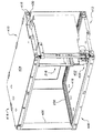
作用を説明すると、フレームアセンブリ214は、リフトフレーム614の前部の開口からリフトフレーム612内に組み込むことができる。したがって、リフトフレーム614は5側面を備えた箱枠(ボックスフレーム)を有しており、フレームアセンブリ214内に収容されたデータ媒体アクセス装置216(図5)が、データ記憶システム100の作動中に、フレームアセンブリ214の周囲に配置されたデータ媒体102にアクセスできるようにする開口が各側面に設けられている。フレームアセンブリ214は、リフトフレームガイド部材4202およびガイド部材4200によってリフトフレーム612内へ案内されることができる。フレームアセンブリ214上のガイド部材4200がリフトフレームガイド部材4202と噛み合って、フレームアセンブリ214をリフトフレーム612に位置あわせさせる。フレームアセンブリ保持ばね4104は、フレームアセンブリ214をリフトフレーム612内にしっかり留めるように構成されている。フレームアセンブリ214をリフトフレーム612から取り外すには、フレームアセンブリ保持ばねをたわませて、それによってフレームアセンブリ214を上記のようにしてリフトフレーム612から取り外せば良い。
【0061】
前述したように、リフトフレーム612内でのフレームアセンブリ214の位置あわせおよび保持を行うための幾つかの他の実施形態がある。たとえば、リフトフレーム612内でのフレームアセンブリ214の位置あわせおよび保持を行うための他の実施形態は、フレームアセンブリをリフトフレーム612内に係合させた後に取り付けることができる捕獲プレート(capture plate)を有することができる。そのようなプレートは、標準形式(一般用)の機械的締結具か、捕獲プレートの容易な取り外し、それゆえフレームアセンブリのリフトフレーム612からの容易な取り外しを可能にする他の手段かによって、リフトフレーム612に固定することができる。リフトフレーム612内でのフレームアセンブリ214の案内および位置あわせを行う幾つかの他の方法が存在する。たとえば、そのような方法は、ガイドピン、プラスチックガイドレール、機械加工された通路(machined way)および精密研削軸系(precision ground shafting)を含む。
【0062】
やはり、リフトフレーム612およびフレームアセンブリ214を着脱可能に取り付ける正確な方法は重要ではない。むしろ、図11に示されているように、リフトフレーム612およびフレームアセンブリ216が着脱可能に取り付けられているため、ハンドリングシステムアクセスパネル112を経由して媒体ハンドリングシステム200をリフトフレーム612から容易に取り外して、データ記憶システム100から取り除くことができることである。前述したように、媒体ハンドリングシステム200と、リフトアセンブリ600または900などのリフトアセンブリとを用いたデータ記憶システムでは、修理および/または交換が必要な状況で、媒体ハンドリングシステム200およびデータ媒体アクセス装置216に簡便にアクセスできることが望ましい。媒体ハンドリングシステム200は、その複雑な性質および精密な要件のため、データ記憶システム100の他の構成部品より故障率がはるかに高いであろう。したがって、サービスおよび/または点検のために媒体ハンドリングシステム200に容易にアクセスできることが望ましいであろう。リフトフレーム612およびフレームアセンブリ214を着脱可能に固定することによって、オペレータおよび/またはサービス作業員は、媒体ハンドリングシステム200に容易にアクセスして、それをデータ記憶システム100から取り出すことができ、リフトアセンブリをも取り外す必要はない。
【0063】
たとえば、媒体ハンドリングシステム200が故障して、修理および/または交換が必要な場合や、点検が必要な場合など、媒体ハンドリングシステム200をデータ記憶システム100から取り出さなければならない状況で、オペレータおよび/またはサービス作業員はハンドリングシステムアクセスパネル112をデータ記憶システム100から取り外すことができる。他に選択可能な実施形態では、ハンドリングシステムアクセスパネル112をちょうつがい式のパネルドアとして構成して、媒体ハンドリングシステム200にアクセスできるようにしてもよい。
【0064】
ハンドリングシステムアクセスパネル112を取り外した(または、ドアとして構成されている場合には開いた)後、オペレータまたはサービス作業員は、フレームアセンブリ214をリフトフレーム614から容易に取り外し、それによって媒体ハンドリングシステム200をデータ記憶システム100から取り出すことができる。媒体ハンドリングシステム200を取り出した後、オペレータまたはサービス作業員は装置の修理および/または必要な点検を実施することができる。その後、フレームアセンブリ214をリフトフレーム612に着脱可能に取り付けることによって、媒体ハンドリングシステム200(または交換品)をデータ記憶システム100内に挿入し直すことができる。
【0065】
III.データ媒体交換機器
前述したように、データ媒体102は、媒体格納装置106のデータ記憶システム100内に格納することができる。上記の図1および図2は、内部に媒体格納装置106を設けることができるデータ媒体交換機器120を示している。データ媒体交換機器120は、少なくとも1つのデータ媒体102にオペレータまたはサービス作業員がアクセスすることを可能にする。オペレータまたはサービス作業員は、データ媒体交換機器120を使用して、その内部に格納されているデータ媒体102のいずれにもアクセスすることができる。たとえば、オペレータまたはサービス作業員は、データ媒体交換機器120を使用して、一定のデータ媒体102を引き出して代わりのデータ媒体102と交換することができる。このように、データ媒体交換機器120は、選択されたデータ媒体102をデータ記憶システム100に入れたり、引き出したりするのに好都合な手段を提供する。
【0066】
当然ながら、データ記憶システム100は、任意の個数のデータ媒体交換機器120を備えることが可能である。たとえば、図1に示されたデータ記憶システム100は、2つのデータ媒体交換機器120を備え、その一方が閉じられており、他方は開いている。しかし、図3に示して前述したように、データ記憶システム100は、複数の縦型スタック300状に配置された多数のデータ交換装置120を備えることができる。これを念頭に置きつつも、話を簡潔にするために、以下には単一のデータ交換装置120について説明する。
【0067】
図12に示されているように、多くの可能な実施形態のうちの1つでは、データ媒体交換機器120は、後退すなわち閉鎖位置と伸長すなわち開放位置との間を移動できるようにデータ記憶システム100に取り付けられたドロワ114と、1つまたは複数のデータ媒体102を受け取る1つまたは複数の媒体格納装置106と、前アクセスパネル110とを備えている。ドロワ114は、1つまたは複数の媒体格納装置106内に収容された1つまたは複数のデータ媒体102を収納するように構成される。
【0068】
図12〜図14を参照すると、ドロワ114の1つの実施形態は、さらに詳細に後述するようにして直接的に取付システム1330内に取り付けられる格納トレー1200を有することができる。格納トレー1200は、1つまたは複数の媒体格納装置106を着脱可能に収容するように構成することができる。図12〜図14に示された格納トレー1200は、2つの媒体格納装置106を収容している。媒体格納装置106は、1つまたは複数のデータ媒体102を収容するように構成することができる。図12〜図14に示された媒体格納装置106は、5つのデータ媒体102を着脱可能に収容するように構成されている。格納トレー1200は、床部分1302、背部分1300ならびに両端壁1202および1204を有するほぼ矩形の部材を備えることができる。格納トレー1200は、実質的に端壁1202および1204間に位置する中央仕切り区画1304も備えている。各端壁1202および1204は、媒体格納装置106を中央仕切り区画1304に押しやるばね部材1306を備えることができるが、ばね部材1306、すなわち、媒体格納装置106を中央仕切り区画1304に押しやることは、必須ではない。
【0069】
格納トレー1200は、金属またはプラスチックなどの、目的の用途に適した広範囲の所望の材料のいずれかから製造することができる。たとえば、多くの可能な実施形態の1つでは、格納トレー1200は、繊維強化ポリカーボネートプラスチック材料から一体部品として成形される。媒体格納装置106も、個々の用途の要求事項に応じて、広範囲の所望の材料のいずれかから製造することができる。たとえば、媒体格納装置106は、繊維強化ポリカーボネートプラスチック材料から成形することができる。
【0070】
ドロワ114は、詳細に後述するように、直接的にガイドレール1332に取り付けられる前アクセスパネル110またはベゼル(図1および図2)も備えることができる。他に選択可能な構造では、前アクセスパネル110を、格納トレー1200に取り付けるどころか、格納トレー1200に一体化することさえできる。前アクセスパネル110は、ドロワ114が後退位置にある時には、データ記憶システム100の前アクセスパネル110の一部となる。前アクセスパネル110は、システムオペレータまたはサービス作業員がドロワ114を引き開けることができる便利な手段にもなる。
【0071】
ドロワ114は、取付システム1330によってデータ記憶システム100に取り付けることができる。図15〜図20を参照すると、取付システム1330は、3つのガイドレール1400、1308および1332を有し、それらは互いに滑り係合状態に取り付けられて、前述したように、ドロワ114を伸長および後退位置間で移動させることができる。ガイドレール1400、1308および1332の各々は、(図16および図18に示された)第1の形状および(図17および図19に示された)第2の形状の2つの形状のうちの一方を有することができる。さらに具体的には、ガイドレール1400および1332は第1の形状を有するのに対して、ガイドレール1308は第2の形状を有することができる。したがって、取付システム1330は3つの個別のガイドレール1400、1308および1332を備えているが、2つのガイドレール形状が必要なだけである。
【0072】
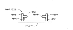
第1の形状を有するガイドレール1400および1332は、図16および図18に最もわかりやすく示されている。ガイドレール1400および1332は、すべての点で互いに同一にすることができる。各ガイドレール1400および1332は、背部分を有する細長部材1600を備え、それから1対のフランジ1602および1604が延出している。第1の軸受けトラック1606が、フランジ1602からほぼ外向きに延出し、フランジ1602および細長部材1600と相まって第1のチャネル1800を形成している。同様に、第2の軸受けトラック1608が、フランジ1604からほぼ外向きに延出し、フランジ1604および細長部材1600と相まって第2のチャネル1802を形成している。図18に示されているように、軸受けトラック1606および1608は細長部材1600に実質的に平行である。各ガイドレール1400および1332の近接(proximal)端部1612付近でチャネル1800および1802内に1対のU字形軸受け部材1610を設けてもよい(図16)。
【0073】
第2の形状を有するガイドレール、たとえば、ガイドレール1308は、図17および図19に最もわかりやすく示されている。ガイドレール1308はほぼ、2を表すローマ数字の“II”の形の断面を有する。第2の形状を有するガイドレール1308は、1対の細長軸受けガイド部材1700および1900を有し、これらが1対のフランジ部材1902および1904によってほぼ平行に間隔を置いて保持されている。第1の軸受けガイド部材1700の、フランジ1902および1904の外側に位置する部分が、軸受けトラック1906および1908を形成している。同様に、第2の軸受けガイド部材1900の、フランジ1902および1904の外側に位置する部分が、軸受けトラック1910および1912を形成している。ガイド部材1700および1900は、第1および第2のフランジ1902および1904と協働して、それぞれ第1および第2のチャネル1914および1916を形成している。
【0074】
第2の形状を有するガイドレール1308の軸受けガイド部材1700および1900はさらに、ほぼ図17に示された位置に複数のU字形軸受け部材1610を備えることもできる。さらに具体的に言うと、4つの軸受け部材1610を下側軸受けトラック1910および1912に取り付けることができ、そのうちの2つの軸受け部材1610がガイドレール1308の近接端部1710付近に、2つの軸受け部材1610がガイドレール1308の中央領域1712付近に設けられる。同様に、4つの軸受け部材1610を上側軸受けトラック1906および1908に取り付けることができ、そのうちの2つの軸受け部材1610が中央領域1712付近に、2つの軸受け部材1610がガイドレール1308の遠心(distal)端1714付近に設けられる。
【0075】
ガイドレール1400、1308および1332は、目的用途に適した広範囲の材料(金属またはプラスチックなど)のうちの任意のもので製造することができる。したがって、本発明は、何らかの特定の材料で作製されたガイドレールに制限されるものと見なされるべきではない。しかしながら、多くの可能な実施形態の1つでは、ガイドレール1400、1308および1332は、押し出し成型されたアルミニウムで形成される。軸受け部材1610も、ガイドレール1400、1308および1332に低摩擦滑り係合するのに適した広範囲の材料で製造することができる。たとえば、1つの可能な実施形態では、各軸受け部材1610はポリサラミド(polythalamide)プラスチックの一体部品として成形される。他の実施形態では、ホィールまたはローラなどの他の形式の軸受けを滑り軸受け1610の代わりに用いることができる。
【0076】
ガイドレール1400、1308および1332は、図15および図20に示されているように、互いに滑り係合することができる。第1の形状を有するガイドレール、たとえばガイドレール1400および1332のチャネル1800および1802が、第2の形状を有するガイドレール、たとえばガイドレール1308の軸受けガイド部材1700および1900に取り付けられたU字形軸受け部材1610を受ける。(同様に、第1の形状を有するガイドレール1400および1332のチャネル1800および1802内に配置されたU字形軸受け部材1610が、第2の形状を有するガイドレール1308の軸受けガイド部材1700および1900に係合する。)
さまざまなガイドレール上のU字形軸受け部材1610の位置は、ガイドレール1400、1308および1332が図15に示された完全伸長位置にある時、ガイドレール1400および1332のチャネル1800および1802内に配置されたU字形軸受け部材1610が、ガイドレール1308の軸受けガイド部材1700および1900に取り付けられたU字形軸受け部材1610に当接できるようにする位置である。さらに具体的には、下側ガイドレール1400上に配置された軸受け部材1610が、下側軸受けトラック1910および1912上の、ガイドレール1308の中央領域1712に配置された軸受け部材1610に当接する。同様に、上側ガイドレール1332上に配置された軸受け部材1610が、上側軸受けトラック1906および1908上の、ガイドレール1308の中央領域1712に配置された軸受け部材1610に当接する。この構造は、オペレータまたはサービス作業員が誤ってドロワ114を伸長位置を越えて引き出してしまい、ひょっとしたらガイドレール1400、1308および1332を引き抜いて分離させてしまうことを防止するであろう。
【0077】
再び図15を参照すると、第1の形状を有するガイドレール1400および1332は、ガイドレールをデータ記憶システム100のハウジング104に取り付け、格納トレー1200をガイドレールに取り付けることができるようにする1つまたは複数の取り付け穴すなわちスロット1500を有することができる。たとえば、多くの可能な実施形態のうちの1つでは、ガイドレール1400が複数のねじ(図示せず)によって直接的にデータ記憶システム100のハウジング104(図14)に取り付けられる。同様に、格納トレー1200も、複数のねじ(図示せず)によって直接的にガイドレール1332に取り付けることができる。他に選択可能な実施形態では、当該技術分野では周知であるか、将来に開発される他の形式の締結具を使用して、ガイドレール1400をハウジング104に取り付け、格納トレー1200をガイドレール1332に取り付けてもよい。
【0078】
IV.自動媒体交換システム
当業者には理解されるように、さまざまな実施形態のデータ媒体交換機器120をさまざまな方法で直接的にデータ記憶システム100に取り付けることができる。たとえば、図15〜図20に関連して詳細に前述したように、データ媒体交換機器120は、直接的に取付システム1330に取り付けることができる。この実施形態では、取付システム1330によってオペレータまたはサービス作業員がデータ媒体交換機器120を手動で伸長および/または後退させることができる。前述したようにデータ媒体交換機器120を伸長および/または後退させることができるようにするさまざまな他のシステムおよび方法が存在する。多くの可能な実施形態の1つでは、自動媒体交換システム3100(図31〜図32)を、取付システム1300およびデータ媒体交換機器120と組み合わせて設けることができる。自動媒体交換システム3100は、オペレータがデータ媒体交換機器120の作動を自動制御できるようにする。言い換えると、自動媒体交換システム3100は、媒体交換装置120をデータ記憶システム100からどこまで後退および/または伸長させるかをオペレータが自動制御できるようにする。このように、オペレータは、特定のデータ媒体交換機器120内にある特定のデータ媒体102を指定することができる。指定された特定のデータ媒体102に基づいて、自動媒体交換システム3100は特定のデータ媒体交換機器120を適切な距離だけ自動的に伸長させて、オペレータがその特定データ媒体102にアクセスできるようにする。自動媒体交換システム3100はまた、オペレータが、たとえば操作盤(コントロールパネル)を用いて、データ媒体交換機器3100をどこまで伸長および/または後退させるかを制御できるようにする。
【0079】
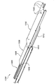
自動媒体交換システム3100は、駆動システム3102と、駆動システム3102に係合した細長駆動部材3112と、取付システム1330などの取付システムとを備えることができる。当業者であれば、自動媒体交換システム3100にさまざまな取付システムを用いることができることを理解できるであろう。詳細に前述したように、取付システム1300は、3つのガイドレール1400、1308および1332を有することができ、これらは互いに滑り係合状態に取り付けられるように構成されて、前述したように、ドロワ114を伸長および後退位置間で移動させることができる。図31を参照すると、多くの可能な実施形態のうちの1つでは、ガイドレール1400が複数のねじ(図示せず)によって直接的にデータ記憶システム100のハウジング104(図14)に取り付けられる。
【0080】
駆動システム3102は、モータ(図示せず)と、モータと噛み合った駆動ギヤ3106と、細長駆動部材3112と、モータ、駆動ギヤ3106および細長駆動部材3112の一部分を収容するためのハウジング3104とを備えることができる。細長駆動部材3112は、第1の端部3120、第2の端部3122、上部分3124(図32)および底部分3126を有する。第1の端部3120は、点3110でガイドレール1308に固定することができる。第2の端部3122は、ハウジング3104内に収容することができる。細長駆動部材3112の上部分3124は、駆動ギヤ3106と噛み合うことができるギヤラック3108にすることができる。当業者であれば、駆動ギヤ3106およびギヤラック3108にはさまざまな構造が存在する事を理解できるであろう。たとえば、駆動ギヤ3106およびギヤラック3108の各々に歯を付けて、駆動ギヤ3106の歯とギヤラック3108の歯とが互いに噛み合うことによって、駆動ギヤ3106が一方向に回転すると細長駆動部材3112がハウジング3104内へ巻取られ、駆動ギヤ3106が他方向に回転すると細長部材3112がハウジング3104内で繰り出される(uncoiled:巻きが解かれる)。細長駆動部材3112はガイドレール1308に固定されているため、駆動ギヤ3106が細長駆動部材3112を繰り出した時、ガイドレール1308がデータ記憶システム100から引き出される。前述したようにガイドレール1308、1332および1400が相互作用するため、駆動ギヤ3106が細長部材3112を繰り出す程度に応じてガイドレール1332も伸びるであろう。駆動ギヤ3106が細長駆動部材3112を巻き取ると、ガイドレール1308(必要時にはガイドレール1332も)がデータ記憶システム100内へと後退する。当然ながら、駆動ギヤ3106および細長駆動部材3112は、底部分3126にギヤラック3108を有するように構成することもできる。さらに、駆動ギヤ3106およびギヤラック3108に歯を付ける必要はない。駆動ギヤ3106が細長駆動部材3112に係合して、(駆動ギヤ3106の回転に応じて)巻き取りおよび繰り出しを行い、それによってガイドレール1308に取り付けられたデータ媒体交換機器120を後退または伸長させることである。
【0081】
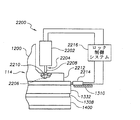
図13、図14および図21を参照すると、データキャリッジ交換装置120はさらに、ドロワ114が完全に後退した位置にある時に媒体格納装置106をより正確に位置決めするために、媒体格納装置整合装置1314を有するであろう。媒体格納装置整合装置1314は、1対の細長基準レール1316および1312を有し、図14に最もわかりやすく示されているように、これらは互いに間隔を置いてデータ記憶システム100のハウジング104に取り付けられている。各媒体格納装置106に第1および第2の細長スロット1320および1322を設けることができ、これらは、ドロワ114を後退位置へ移動させた時、それぞれの細長基準レール1316および1312に滑り係合する大きさである。細長基準レール1316および1312が媒体格納装置106の対応スロット1320および1322に係合することによって、媒体格納装置106がドロワ114からわずかに上昇し、図21に最もわかりやすく示されているように、媒体格納装置106が整合位置2104に保持される。したがって、ドロワ114を完全に後退させた時、媒体格納装置106の位置は、ドロワ114ではなく媒体格納装置整合装置1314によって決定されるであろう。
【0082】
媒体格納装置整合装置1314は、媒体格納装置106がドロワ114の格納トレー1200内に据えられたままである場合よりも、媒体格納装置106をより正確に位置決めする。媒体格納装置整合装置1314によってより正確に位置決めされることによって、媒体ハンドリングシステム200が選択データ媒体102に適切に係合できる可能性が相当高くなる。この構造はまた、高精度ドロワ取付システムを設ける必要をなくす。言い換えると、媒体格納装置106がドロワ114によって固定位置に保持されるわけではないため、ドロワ114は、ドロワ114を閉じる毎に媒体格納装置106を正確な位置に戻すように構成する必要がない。
【0083】
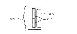
図22および図23を参照すると、別の実施形態では、データカートリッジ交換装置120は、ドロワ114を完全後退位置に保持するためのドロワロック装置2200を有することができる。ドロワロック装置2200は、ロックボルトすなわちプランジャ2204をロック位置2206および解除位置2208間で移動させるロックアクチュエータ2202を有することができる。ロックボルト2204を解除位置2208に付勢するために、ばね(図示せず)を用いてもよい。ロックボルト2204は、ドロワ114に固定されたロックプレート2212に設けられた複数の穴2210のうちの少なくとも1つにはまる大きさにすることができる。リミットスイッチ2214をデータ記憶システム100のハウジング104に取り付けて、ドロワ114が完全閉鎖すなわち後退位置にある時にロック制御システム2216に信号を送ることができる。
【0084】
ロックプレート2212は、格納トレー1200に一体化されていても良い。しかし、格納トレー1200は右側ドロワ114(図14)または左側ドロワ114’(図14)のいずれにも使用できるように構成されるので、格納トレー1200は2つのロックプレート2212および2212’を備えて、格納トレー1200の各端部に1つずつ配置される(図14)。この構造によって、単一の格納トレー1200を180°回転させるだけで、右側または左側ドロワ114のいずれにも使用することができる。さらに、ロックアクチュエータ2202は、ガイドレール1332の中心線に沿って配置しないで、わずかに一方側に片寄らせることができる。したがって、ロックプレート2212は、2つの穴2210を備えることができ、これによっても、同一の格納トレー1200およびロックプレート2212を右側または左側構造のいずれにも使用できるようになる。
【0085】
ドロワロック装置2200のさまざまな構成部材は、当該技術分野では周知であって市販されている広範囲の装置およびシステムを有することができる。たとえば、ロックアクチュエータ2202は、ロックプレート2212に設けられた穴2210の少なくとも1つにはまる寸法のプランジャ2204を有する電動式ソレノイドを備えることができる。ロックアクチュエータ2202は、適切なばね(図示せず)によって解除位置2208に押しつけることができる。したがって、ソレノイドが励磁された時、それはロックボルト2204をロック位置2206へ移動させる。当然ながら、当業者であれば、さまざまな他の形式の構成部材および作動構造も使用できることを理解できるであろう。
【0086】
データカートリッジ交換装置120は次のように作動して、オペレータまたはサービス作業員がデータ記憶システム100内に収容されているさまざまな媒体102にアクセスできるようにする。たとえば、データ記憶システム100に複数のデータ媒体102が設けられている状況を考える。通常の作動中、ドロワ114は図示のように閉鎖すなわち後退位置に保持され、したがって、媒体ハンドリングシステム200(図2および図4)はデータ記憶システム100内に収容されたすべてのデータ媒体102にアクセスすることができる。オペレータまたはサービス作業員が1つまたは複数のデータ媒体102にアクセスし、たとえば、1つまたは複数のデータ媒体102を取り出して別のデータ媒体102と置き換える必要が生じた場合、オペレータまたはサービス作業員はドロワ114の前アクセスパネル110を引いて、ドロワ114を伸長位置へ移動させる。データ記憶システム100が自動媒体交換システム3100を備えている場合、オペレータまたはサービス作業員は、操作盤および/またはホストコンピュータからドロワ114の伸長および/または後退を自動的に制御することができる。オペレータまたはサービス作業員は、アクセスする必要がある特定のデータ媒体交換機器120内の特定のデータ媒体102を入力する。データ記憶装置100は、ドロワ114内の各データ媒体102の正確な位置と、オペレータまたはサービス作業員がデータ媒体102にアクセスできるようにするためにドロワ114を伸長させなければならない所定距離と、を収めた論理を含むことができる。したがって、オペレータまたはサービス作業員が選択した特定のデータ媒体102と所定の論理とに基づいて、制御システム(図示せず)はモータを制御して駆動ギヤ3106と噛み合わせて、ガイドレール1308が(必要に応じて、ガイドレール1332および1400と共に)ドロワ114を所定距離まで伸長させるように、細長駆動部材3112を繰り出す。オペレータまたはサービス作業員は、モータおよび駆動ギヤ3106を制御することによってドロワ114の伸長および/または後退を自動制御することもできる。
【0087】
データ媒体交換機器120がドロワロック装置2200を備えている場合、ロック制御システム2216は最初に、ロックアクチュエータ2202を作動させてロックボルトすなわちプランジャ2204を解除位置2208へ移動させ、それによって、媒体ハンドリングシステム200(図2および図4)がドロワ114内のすべてのデータ媒体102にアクセスできるようになる。ロック制御システム2216は、制御システム(図示せず)からの信号によって、あるいはオペレータまたはサービス作業員が操作盤(図示せず)を用いて、係合させる(engaged)ことができる。ドロワ114を開放すなわち伸長させた後、オペレータまたはサービス作業員は露出したデータ媒体102にアクセスして、データ媒体102の交換、取り出しまたは置き換えを行うことができる。ドロワ114が伸長位置にある間、データ記憶システム100は作動可能状態にあり、媒体ハンドリングシステム200は他の媒体格納装置106内に格納されているデータ媒体102にアクセスし続けることができる。オペレータまたはサービス作業員が露出データ媒体102にアクセスする必要がなくなった時、ドロワ114の前アクセスパネル110を押して、ドロワ114を後退位置に戻す。ドロワ114が後退位置へ移動すると、細長基準レール1316および1312が媒体格納装置106の対応スロット1320および1322にはまるであろう。スロット1320および1322に完全にはまった時、基準レール1316および1312は媒体格納装置106をドロワ114からわずかに上昇させて、各媒体格納装置106を図21に示された整合位置2104に保持する。
【0088】
ドロワ114が後退位置に戻った後、マガジンセンサスイッチが作動して、ドロワ114を閉鎖すなわち後退位置にロックするためにドロワロック装置2200を作動させることをロック制御システム2216に命令するようにデータ記憶システム100を作動させる。その後、データ記憶システム100は、データ記憶システム100内に収容されているデータ媒体102の「目録(インベントリ)を作り直す」(re-inventory)。本例では、データ記憶システム100はドロワ114内に収容されているデータ媒体102の目録を作り直すだけでよい。というのは、オペレータまたはサービス作業員が交換、取り出しまたは置き換えを行うことができるのが、これらのデータ媒体102だけであるからである。
【0089】
ドロワ114に載せられているさまざまなデータ媒体102が1つまたは複数の媒体格納装置106に収容されているようにデータ媒体交換機器120が構成されている場合、データ交換装置120によって、媒体格納装置全体を取り出して交換することが可能になる。たとえば、ドロワ114が2つの媒体格納装置106を収容するように構成され、各媒体格納装置が5つのデータ媒体102を収容するように構成されている場合、オペレータまたはサービス作業員が媒体格納装置106全体を取り外して、媒体格納装置106内に収容されている複数のデータ媒体102の交換、取り出しまたは置き換えを簡便に行うことができる。オペレータまたはサービス作業員が媒体格納装置106を簡便に持ち運ぶことができるように、媒体格納装置106にハンドル30を設けてもよい。
【0090】
図1、図2および図12に最もわかりやすく示されているように、データ媒体交換機器120は、ハウジング114および前アクセスパネル110の厚さのために、媒体ハンドリングシステム200のデータ媒体アクセス装置216がアクセスできない未使用スペースを端壁1202と前アクセスパネル110との間に有する。図24〜図26は、同様にデータ記憶システム100内に設けることができるデータ媒体交換機器2400の別の実施形態を示している。
【0091】
データ媒体交換機器2400は、データ媒体交換機器120とほぼ同様に構成することができる。データ媒体交換機器2400も、直接的に取付システム1330に取り付けて、データ媒体交換機器120に関連して前述したようにして作動されることができる。しかし、データ媒体交換機器2400はさらに、端壁1202と前アクセスパネル110との間に位置する補助格納機器2402を有する。補助格納機器2402は、1つまたは複数のスロット部材2404およびベース部材2405で形成された複数のスロット2408を有する。ベース部材2405は前端壁1202から延び出て、スロット2408内に収容されたデータ媒体102を支持するベースを提供する。スロット部材2408は、ベース部材2405から離れる方向に突き出している。図25に示されているように、ベース部材2405および1つまたは複数のスロット部材2408は、予備データ媒体2500を収容する1つまたは複数のスロット2408を提供する。ハウジング104および前アクセスパネル110の厚さ、および媒体ハンドリングシステム200の構造のせいで、スロット2408およびそれに収容されたデータ媒体2500は媒体ハンドリングシステムにとってはアクセスできないであろう。
【0092】
当業者であれば、端壁1202と前アクセスパネル110との間の正確な体積は、データ媒体交換機器2400、データ媒体102、媒体格納装置106およびデータ記憶システム100の正確な寸法および構造などのさまざまな要素に応じて変化するであろう。したがって、補助格納機器2402内のスロット2408およびスロット部材2404の数は変化するであろう。さらに、スロット2408およびスロット部材2404の正確な寸法および構造は、格納スロット2408内に収容されるデータ媒体2500のタイプによっても変化するであろう。たとえば、図24〜図26に示された多くの可能な実施形態の1つでは、端壁1202と前アクセスパネル110との間の体積は、データ媒体交換機器2400の補助格納機器2402が、それぞれデータ媒体2500を収容する2つのスロット2408を設けることができるようにする。本例では、端壁1202に隣接したスロット2408が、スロット部材2404とベース部材2405と端壁1202とによって定められる。あるいは、端壁1202に隣接したスロット2408を2つのスロット部材2404で定めてもよい。同様に、前アクセスパネル110に隣接したスロット2408は、スロット部材2404と、前アクセスパネル110またはデータ交換装置2400の他のいずれかの構成部材とによって定めることができる。代わりに、前アクセスパネル1202に隣接したスロット2408を2つのスロット部材2404で形成してもよい。端壁1202に隣接したスロット2408および前アクセスパネル110に隣接したスロット2408を共通のスロット部材2404で画定しても、そうでなくてもよい。さらに、補助格納機器2402が3つ以上のスロット2408を有する場合、各対の内側スロット2408を共通スロット部材2404で画定しても、そうでなくてもよい。
【0093】
補助格納機器2402は、目的用途に適した広範囲の所望材料のいずれか、たとえば、金属またはプラスチックで製造することができる。多くの可能な実施形態の1つでは、補助格納機器2402を繊維強化ポリカーボネートプラスチック材で一体部品として成形することができる。補助格納機器2402は、格納トレー1200と一体化して形成してもよい。他の実施形態では、補助格納機器2402を格納トレー1200から分離した構成部材として形成することができ、その場合、補助格納機器2402は、格納トレー1200またはデータ媒体交換機器2400の他の構成部材に固定することができる。
【0094】
前述したように、データ媒体交換機器2400は、データ媒体交換機器120とほぼ同様に構成して作動させることができる。しかし、補助格納機器2402は、予備データ媒体2500をデータ記憶システム100の外部の他の場所に保管するのではなく、データ媒体交換機器2400内に格納できるようにする。したがって、補助格納機器2402は、予備データ媒体2500を他の場所に配置するという負担を伴わないで、オペレータまたはサービス作業員が媒体格納装置106内に収容されたデータ媒体102の交換に使用できる予備データ媒体2500に迅速にアクセスできるようにする。
【0095】
V.媒体交換/格納統合型装置
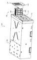
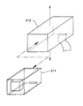
図27〜図30は、1つまたは複数のデータ媒体102を収容できる構造であって、オペレータまたはサービス作業員が細長基準レール1316および1312(図13および図21)に滑り係合させることによってデータ記憶システム100に対して容易に挿抜することができる統合化された媒体交換/格納装置2700を示している。
【0096】
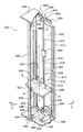
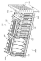
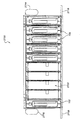
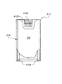
媒体交換/格納統合型装置2700は一般的に、端部分2704および2706、上部分2708、底部分2710および側部分2712および2714を有するハウジング2702と、ハウジング2702に取り付けられた1つまたは複数のハンドル2716と、ハウジング2702に取り付けられて少なくとも1つの穴2720を設けた1つまたは複数のロックプレート2718とを備えている。側部分2712は、データ媒体102を収容できるように構成された複数のスロット2722を有する。スロット2722は、ハウジング2702内の間隔の空けられた複数の仕切り2724によって形成することができる。仕切り2724は、端部分2706および2704に平行であって、データ媒体102をスロット2722内に案内するのに役立つ斜面縁部を有することができる。スロット2722は、やはりデータ媒体102をスロット2722内に案内するのに役立つ傾斜面を底部分2710に有することができる。詳細に後述するように、細長基準レール1316および1312に滑り係合するために、ハウジング2702の上部分2708に、細長基準レール1316(図13および図21)に係合する細長スロット(整合溝)2750が設けられ、底部分2710に、細長基準レール1312(図13および図21)に係合する細長スロット2752が設けられている。
【0097】
当業者であれば、媒体交換/格納統合型装置2700の正確な構造が、データ媒体102およびデータ記憶システム100の正確な寸法および構造などのさまざまな要素に応じて変化することは理解できるであろう。したがて、スロット2722および仕切り2724の数は変化するであろう。さらに、スロット2722およびスロット部材2724の正確な寸法および構造も、スロット2722内に収容されるデータ媒体102のタイプに応じて変化するであろう。たとえば、図27〜図29に示された、多くの可能な実施形態のうちの1つでは、媒体交換/格納統合型装置2700は、データ媒体102を収容するために10個のスロット2722を有する。さらに、仕切り2724は、上部分2708から底部分2710までの全長にわたって架け渡される必要はない。仕切り2724は、データ媒体102をスロット2722に案内できる構造であることが好ましい。たとえば、この例に制限する意図ではないが、仕切り2724は、上部分2708から下向きに延出する部分および底部分2710から上向きに延出する部分の2つの小さい仕切り部分を有することができる。仕切り2724は、底部分2710から突き出ているが上部分2708には届かないか、または上部分2708から突き出ているが底部分2710には届かないといった単一の断片によって構成されていても良い。
【0098】
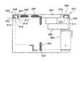
媒体交換/格納統合型装置2700は、データ媒体102をスロット2722内に配置された状態に保持するために、ハウジング2702の上部分2708に固定されたばね機構2730も有することができる。ばね機構2730は、データ媒体102をハウジング2702のスロット2722内に固定する力を与える。ハウジング2702の上部分2708は、ばね機構2730をハウジング2702に固定するために使用される複数の仕掛けを有することができる。上部分2708は、複数のばねロック2732(図29)を有することができる。ばねロック2732は、左部分、右部分、上部分および開口を有する。左部分および右部分は、ハウジング2702の上部分2708に垂直に突出することができる。ばねロック2732の上部分は、左部分および右部分の間に広がって、開口を形成している。ばねロック2732は、たとえば、ハウジング2702の上部分2708に一体成形してもよい。ハウジング2702の上部分2708は、上部分2708に一体成形された1つまたは複数のばねガイド2734も有することもできる。ばねガイド2734は、後述するように、ハウジング2702の上部分2708に対してばね機構2730を整合(位置合わせ)させるのに役立つ。
【0099】
前述したように、ばね機構2730は、ハウジング2702の上部分2708に取り付けることができる。ばね機構2730は、取付部分2736と複数のフィンガ2738とを有することができる。フィンガ2738は、前部分2740、後部分2742および中間部分2744を有することができる。
【0100】
好適な実施形態では、前部分2740は幅が約7mmであり、後部分2742は幅が約4mmである。フィンガ2738は、長さが約40mmである。フィンガ2738が先細形状であることによって、両形式のフィンガに同一応力を加えた時には、先細でないフィンガと比べてフィンガ2783のたわみを大きくすることができる。
【0101】
取付部分2736は、ばね機構2730の前縁部2746と反対の位置に複数のばねタブ(図示せず)を有することができる。前縁部2746は、ばねガイド2734に当接することができる。ばねガイド2734は、ばねロック2732の開口(図示せず)にはまることができる。ばねガイド2734とばねロック2732との組み合わせによって、締結具を必要としないで、ばね機構2730をハウジング2702の上部分2708に取り付けることができる。それらはさらに、ばね機構2730をハウジング2702に対して適切に整合させる。
【0102】
ばね機構2730は、たとえば、約0.635mm厚さの301ステンレス鋼の単一板材で形成することができる。ステンレス鋼を使用することによって、ばね機構2730が腐食する可能性が減少する。フィンガ2738の剛さは、ばね機構2730の材料、材料厚さ、フィンガ2738の幅および当該技術分野では周知の他の要素の選択を含む周知の機械技術によって選択することができる。
【0103】
図30に最もわかりやすく示されているように、フィンガ2738の後部分2742にロック部材3000を設けることができる。ロック部材3000は、フィンガ2738の後部分2742に固定することができる。ロック部材3000は、データ媒体をハウジング2702内に固定するのに役立つであろう。図30は、データ媒体102がスロット2722に入った状態におけるデータ媒体交換/格納統合型装置2700の断面図である。ロック部材3000は、たとえば、ペンシルバニア州エクストンのエル・ネヌ・ピー・エンジニアリング・プラスチックス・カンパニ(LNP Engineering Plastics Company)が製品番号QCL−4036で市販している、炭素繊維およびPTFEを添加して改質(変性)されたナイロン6−10から成形される。ロック部材3000は、ロック部材3000をフィンガ2738上に成形することによって、フィンガ2738の後部分2742に取り付けることができる。
【0104】
ロック部材3000は、上部分3002、後部分3004および前部分3006を有する三角形に概ねすることができる。後部分3004および前部分3006は、点3008で交差している。基準線AAを上部分3002に平行に伸ばし、点3008と交わらせる。基準線AAと後部分3004との間に、たとえば55°の背面角3010が存在する。基準線AAと前部分3006との間に前面角3012が存在する。図30に示された実施形態では、ロック部材3000は、データ媒体/格納統合型装置2700のスロット2722内にデータ媒体102を固定するのに役立つ。
【0105】
前述したように、データ媒体/格納統合型装置2700は、ハウジング2702に取り付けられたハンドル2716を有することができる。ハンドル2716は、端部分2704および/または2706に旋回式(回転可能)に取り付けることができる。図27〜図30に示された実施形態では、データ媒体/格納統合型装置2700は、データ記憶システム100(図1および図2)に使用できるように構成されている。したがって、データ媒体/格納統合型装置2700は好ましくは、両端部分2704および2706にハンドル2716を有する。このようにして、データ媒体/格納統合型装置2700は、データ記憶システム100の右側または左側のいずれでも用いることができる。この構造のため、単一の対称的なデータ媒体/格納統合型装置2700を製造することができる。
【0106】
前述したように、細長スロット(整合溝)2750および2752を図13および図21を参照しながら詳細に説明したように細長基準レール1316および1312にそれぞれ滑り係合させることによって、オペレータまたはサービス作業員はデータ媒体/格納統合型装置2700をデータ記憶システム100に対して容易に挿抜することができる。
【0107】
データ媒体交換/格納統合型装置2700は、端部分2704および/または端部分2706に固定されたロックプレート2718も有する。ロックプレート2718は、データ記憶システム100のロック装置2200(図22)と組み合わせて使用することができる。詳細に前述したように、ロック装置2200は、プランジャすなわちロックボルト2204をロック位置2206および解除位置2208間で移動させるためのロックアクチュエータ2202を備えることができる。ロックボルト2204は、データ媒体交換/格納統合型装置2700のロックプレート2718に設けられた穴2720にはまる寸法である。データ記憶システム100のシャーシ1310に取り付けられたリミットスイッチ2214が、データ媒体交換/格納統合型装置2700がデータ記憶システム100内に完全に挿入された時を検出する。リミットスイッチ2214は、ロックアクチュエータ2202を上記のように作動させるために使用されるロック制御システム2216に接続されるであろう。
【0108】
データ媒体交換/格納統合型装置2700は以下のように作動して、オペレータ(図示せず)がデータ記憶システム100内のデータ媒体交換/格納統合型装置2700内に収容されているさまざまなデータ媒体102にアクセスできるようにする。データ記憶システム100の通常作動中、データ媒体交換/格納統合型装置2700は細長スロット(整合溝)2750および2752と細長基準レール1316および1312とによってデータ記憶システム100内に滑り係合される。データ媒体交換/格納統合型装置2700がデータ記憶システム100に挿入されている間には、データ記憶システム100内の媒体ハンドリングシステム200(図2および図4)が、スロット2722内に収容されているすべてのデータ媒体102にアクセスすることができる。そこで、たとえば、データ媒体102のうちの1つまたは複数を取り出し、それを代わりのデータ媒体102(図示せず)と置き換えるなどのためにオペレータが1つまたは複数の媒体102にアクセスする必要が生じた場合、オペレータは前パネル110を取り外すか、開放する。次に、オペレータは、ハンドル2716を引いてデータ媒体交換/格納統合型装置2700を整合装置1314から滑り出させる。オペレータがハンドル2716を引っ張ると、細長スロット2750(整合溝)および2752が細長基準レール1316および1312上を摺動し、それによってデータ媒体交換/格納統合型装置2700を取り外すことができる。データ記憶システム100にロック装置2200が設けられている場合、データ媒体交換/格納統合型装置2700のロックを解除することをロック制御システム2216に最初に命令しなければならないであろう。ロック制御システム2216には、制御システム(図示せず)によって、またはオペレータが操作盤112によって命令することができる。
【0109】
データ媒体交換/格納統合型装置2700が部分的に伸ばされるか、取り外されると、オペレータは露出データ媒体102にアクセスして、それらの交換、取り出しまたは置き換えを行うことができる。データ媒体交換/格納統合型装置2700が部分的に伸ばされるか、取り外されている間、データ記憶システム100は作動可能状態にあり、媒体ハンドリングシステム200は、他のデータ媒体交換/格納統合型装置2700ならびに/またはデータ媒体交換機器120および2400内に格納されたデータ媒体102にアクセスし続けることができる。しかし、媒体ハンドリングシステム200は、部分的に伸ばされるかまたは取り外されているデータ媒体交換/格納統合型装置2700内に収容されているデータ媒体にアクセスしないであろう。
【0110】
オペレータがむき出しのデータ媒体102にアクセスする必要がなくなると、オペレータはデータ媒体交換/格納統合型装置2700をデータ記憶システム100に挿入することができる。細長基準レール1316および1312がデータ媒体交換/格納統合型装置2700の対応の細長スロット(整合溝)2750および2752に係合するようにして、データ媒体交換/格納統合型装置2700をデータ記憶システム100に押し込まなければならない。スロット(整合溝)2750および2752に完全に係合した時、基準レール1316および1312はデータ媒体交換/格納統合型装置2700をわずかに上昇させ、それによって媒体ハンドリングシステム200がスロット2722内の所望データ媒体102を迅速に位置を探し当てることができる。
【0111】
データ媒体交換/格納統合型装置2700を完全に挿入した後、ロック制御システム(図22)がロック装置2200を操作して、ロックボルト2204をロックプレート2718の穴2720に挿入する。その後、データ記憶システム100は、データ記憶システム100内に格納されているデータ媒体102の「目録を作り直す」ことができる。本例では、データ記憶システム100は、データ媒体交換/格納統合型装置2700内に収容されているデータ媒体102の目録を作り直すだけでよい。というのは、オペレータが交換、取り出しまたは置き換えを行うことができるのが、これらのデータ媒体102だけであるからである。
【0112】
VI.一括(バルク)データ媒体アクセスシステム
前述したように、媒体格納装置106およびデータ媒体102は、さまざまな装置およびさまざまな方法でデータ記憶システム100内に組み入れることができる。たとえば、データ媒体102は、データ記憶システム100に対して容易に挿抜できるデータ媒体交換/格納統合型装置2700などの媒体格納装置106内に組み入れることができる。この形式の構造では、媒体格納装置106は滑り機構で挿抜することができる。データ媒体102は、たとえばデータ媒体交換機器120および2400などのドロワ構造を有する媒体格納装置106内に組み入れることもできる。ドロワ構造では、各媒体格納装置106が個別のアクセス手段からアクセスされることが可能である。たとえば、複数の縦型スタック300状に配置することができる複数のデータ媒体交換機器120および2400を備えたデータ記憶システム100について考える。ドロワ構造では、各データ媒体交換機器120および2400は、装置へのアクセス用の個別の手段に対応している。具体的に言うと、オペレータは、ドロワ114の伸長および後退によってデータ媒体交換機器120または2400内に格納されたデータ媒体102にアクセスすることができる。したがって、データ記憶システム100内の各データ媒体交換機器120および2400は、個別のアクセス手段および個別のロック手段を用いている。
【0113】
図38〜図40を参照しながら、データ記憶システム100用の一括データ媒体アクセスシステム3900を説明する。媒体格納装置106およびデータ記憶システム100の正確な構造に関係なく、一括データアクセスシステム3900は、データ記憶システム100内に配置された複数の媒体格納装置106にアクセスする単一の手段を備えている。言い換えると、一括データ媒体アクセスシステム3900は、各媒体格納装置用に個別アクセス手段および個別ロック手段を設ける必要が無い。
【0114】
一括データ媒体アクセスシステム3900は、連続的に配置された複数の媒体格納装置106の少なくとも一部分にアクセスする一括アクセス装置3902を提供する。図39および図40に示されているように、多くの可能な実施形態のうちの1つでは、一括アクセス装置3902は、複数の縦型スタック300状に配置された複数の媒体格納装置106に対して単一のアクセス手段を備えるように構成することができる。当業者であれば、一括アクセス装置3902をさまざまな他の方法で構成できることを理解できるであろう。たとえば、一括アクセス装置3902は、水平方向に複数列にして配置された複数の媒体格納装置に対して単一のアクセス手段を備えるように構成してもよい。一括アクセス装置3902の正確な構造は、任意の連続配置された媒体格納装置106に合わせて変更することができる。重要な点は、一括アクセス装置3902によってオペレータが一度に複数の媒体格納装置106にアクセスできることである。
【0115】
したがって、一括媒体アクセスシステム3900は、複数の一括アクセス装置3902を用いてもよい。好適な実施形態では、一括媒体アクセスシステム3900が、図3、図39および図40に示されているように、媒体格納装置106が複数の縦型スタック300状に配置されているデータ記憶システム100で用いられる。各縦型スタック300内において、図2に示されているように、媒体格納装置106が媒体ハンドリングシステム200の両側に配置されている。したがって、2群(グループ)の連続的な媒体格納装置106が設けられ、一方はデータ記憶システム100の一方側の連続媒体格納装置106の縦配置によって定まり、他方はデータ記憶システム100の他方側の連続媒体格納装置106の縦配置によって定まる。したがって、この実施形態では好ましくは、一括媒体アクセスシステム3900に2つの一括アクセス装置3902が設けられる。
【0116】
さらに、一括アクセス装置3902は、複数の媒体格納装置106に対して単一のアクセス手段を備えるように、さまざまなやり方でデータ記憶システム100に取り付けることができる。図38〜図40に示されているように、一括アクセス装置3902は、データ記憶システム100のハウジング104にちょうつがいを用いて取り付けられたドアとして構成することができる。一括アクセス装置3902は、データ記憶システム100のハウジング104に対して容易に着脱することができる取り外し式パネルとして構成することもできる。一括アクセス装置3902が好ましくは、連続的に配置された複数の媒体格納装置106に対する単一のアクセス手段を提供することである。
【0117】
図38に例示されるように、一括アクセス装置3902はさらに、一括装置3902の媒体格納装置106側とは反対側に取り付けられた複数のばねパッド3912を有することができる。各ばねパッド3912は、対応する媒体格納装置106と向き合わせて配置されている。ばねパッド3912は、一括装置3902が閉鎖され、かつ/またはデータ記憶システム100に対して取り付けられた時に、媒体格納装置106に対して力を加える、フォーム(foam)パネル、受動的なばね機構または他の機構として構成することができる。このように、ばねパッド3912は、媒体格納装置106を媒体ハンドリングシステム200に対して所定位置に保持し、それによってデータ記憶システム100の効率的作動を促進する。
【0118】
一括アクセス装置3902は、一括アクセス装置3902をデータ記憶システム100のハウジングに対してロックするように構成されたロック機構3904も備えている。多くの可能な実施形態の1つでは、ロック機構3904は、一括アクセス装置3902をロックするための2つのシステム、すなわち、キーロック機構と、データ記憶システム100に関連した制御システムによって制御された電子ロック機構とを含む。キーロック機構は、一括アクセス装置3902に取り付けられてデータ記憶システム100内のキーロックラッチ(図示せず)に係合するように構成されたドアキーロック3914を有することができる。キーロック3914およびキーロックラッチは、キーロック3914およびキーロックラッチが係合したロック状態と、キーロック3914およびキーロックラッチが係合していないロック解除状態とを有することができる。
【0119】
ロック機構3904はまた、安全をさらに確実なものにするために電子ロック機構を有することができる。電子ロック機構は、データ記憶システム100に関連した制御システムと連携するように構成することができる。多くの可能な実施形態のうちの1つでは、電子ロック機構は、データ記憶システム100内に収容されて制御システムによって制御されるソレノイドなどの電気機械式装置3910と、一括アクセス装置に固定されたドアラッチ3906とを有することができる。電気機械装置3910およびドアラッチ3906は、装置3910およびドアラッチ3906が係合したロック状態と、装置3910およびドアラッチ3906が係合していないアンロック状態とを有することができる。
【0120】
作用を説明すると、ロック機構3904は、データ記憶システム100に対して2段階の安全性を与えることができる。したがって、一括アクセス装置3902に関連した媒体格納装置106にアクセスするために、オペレータまたはサービス作業員は、電子機構およびキーロック機構の両方のロックを解除しなければならない。オペレータは、キーを使用して、キーロック3914およびキーロックラッチを解除状態にしなければならない。さらに、オペレータは、装置3910およびドアラッチ3906を解除状態にしなければならない。両機構のロックが解除された後、一括アクセス装置3902は開放されて関連の媒体格納装置106にアクセスすることができる。
【0121】
電気機械ロックは、媒体ハンドリングシステム200の作動中にはユーザがデータ記憶システム100の機能領域(functional area)にアクセスすることができないように設計された安全要求事項を満たすために使用される。これは、ユーザの被り得る負傷を防止する。それによってさらに、データ記憶システム100に関連した制御システムが、データ媒体102へのアクセスのタイミングに対する制御を維持できるようになる。そうでない場合には、ユーザは、データ記憶システム100がアクセス中であるデータ媒体102の取り出しまたは位置の切り換えを行うことができる。データ記憶システム100が期待される位置(ロケーション)にデータ媒体102を見つけることができない場合、それはエラーを発生するであろう。オープン(開)状態では、電気機械式ロックはシャットダウンするか、機能停止(フェイル)しなければならない(これによって、データ媒体102にアクセスできる)。仮にそうしないと仮定すると、停電中または機械的破損中にユーザのデータがデータ記憶システム100内に捕らえ込まれ(トラップされ)てしまう。キーロックは、停電の際か、他の理由によるデータ記憶システム100のパワーダウンの際に、データ媒体102への不正アクセスを防止する安全性を与える。
【0122】
VII.ばね保持システム
前述したように、データ媒体交換/格納統合型装置2700は、ハウジング2702の上部分2714に固定されてデータ媒体102をスロット2722内の位置に保持するばね機構2730を有することができる。ばね機構2730は、データ媒体102をハウジング2702のスロット2722内に固定する力を与える。図27〜図30に関連して前述した実施形態では、ばねガイド2734とばねロック2732との組み合わせによって、締結具を必要としないで、ばね機構2730をハウジング2702の上部分2714に取り付けることができる。それらはさらに、ハウジング2702に対してばね機構2730を適切に整合させる。
【0123】
当業者であれば、ばね機構2730をハウジング2702に取り付けるさまざまな他の方法が存在することを理解でき、その幾つかを以下に説明する。ばね機構2730をハウジング2702に取り付けるこれらのシステムおよび方法は、たとえば、データ媒体交換/格納統合型装置2700、媒体格納装置106、または米国特許第6,042,205号に開示されているものを含む、データ媒体102用の他の格納装置などのさまざまな装置に組み込むことができる。
【0124】
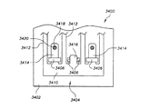
図33および図34を参照しながら、データ媒体102をデータ媒体格納装置内に保持するためのばね保持システム3400を説明する。ばね保持システム3400は、ばね機構2730に関連して前述したのとほぼ同様の態様で作動するように構成することができる。したがって、ばね保持システム3400は、任意のさまざまな媒体格納装置のハウジング3402の1側面、たとえば上部分に取り付けられたばね機構3404を備える。
【0125】
ばね機構3404は、データ媒体102をハウジング3402内のスロット(図示せず)内に固定するための力を与える。ハウジング3402の上部分は、複数のばね整合部材3406および1つまたは複数のばね保持部材3418を有することができる。ハウジング3402の上部分は、それぞれが左部分、右部分、上部分および開口を有する複数のばね整合部材3406を有することができる。左部分および右部分は、ハウジング3402の上部分に垂直に延び得る。ばね整合部材3406の上部分は、左部分および右部分間で広がり、開口を形成する。ばね整合部材3406は、たとえば、ハウジング3402の上部分に一体成形することができる。
【0126】
ハウジング3402の上部分は、ハウジング3402の上部分から延びる1つまたは複数のばね保持部材3418も有することができる。詳細に後述するように、作動中には各ばね保持部材3418がばね機構3404内の穴3420に整合して、ばね整合部材3406と協働する。したがって、ばね保持部材3418および穴3420には多数の構造(形態)がある。図34に断面で示すように、1つの実施形態では、ばね保持部材3418がほぼ三角形であって、対応のばね整合部材3406と向き合う傾斜角を有する。ばね保持部材3418は、ハウジング3402の上部分に一体成形してもよいが、代替例では、ハウジング3402の上部分に取り付けてもよい。
【0127】
ばね機構3404は、ハウジング3402の上部分に取り付けることができる。ばね機構3404は取付部分3410を有し、それから複数のフィンガ3412と1つまたは複数の細長ばねタブ3414とが延びている。フィンガ3412は、フィンガ2730(図29を参照)とほぼ同様に構成することができる。前述したように、各細長ばねタブ3414に穴3420が設けられている。穴3420は、ハウジング3402のばね保持部材3418に整合するようにして細長ばねタブ3414に配置されている。穴3420はまた、ハウジング3402のばね保持部材3418の上に位置してそれによって保持されるように構成されている。ばね機構3404はまた、同様に取付部分3410から延びる1つまたは複数のばねタブ3416を有することができる。ばねタブ3416は好ましくは穴3420を有しておらず、長さが細長ばねタブ3414より短い。
【0128】
図34に示されているように、ばね保持システム3400は、ばね機構3404をハウジング3402に取り付ける簡便な方法を提供する。たとえば、ばね機構3404をハウジング3402の上部分に平坦に当接させ、細長ばねタブ3414をばね整合部材3406の開口に滑り込ませることによって、ばね機構3404をハウジング3402に取り付けることができる。ばね機構3404がハウジング3402の上部分を横切るように摺動(スライド)してばね保持部材3418と接触した時、細長ばね部材3414は、穴3420がばね保持部材3418に係合するまでたわむ。細長ばね部材3414は、滑り移動およびばね保持部材3418との係合の結果として自動的にたわむ必要はない。たとえば、細長ばね部材を手動でたわませて、ばね保持部材3418と協働するように配置してもよい。このように、ばね整合部材3406がばね機構3404を横および垂直移動に関して保持する一方、穴3420およびばね保持部材3418の係合によって、ばね機構3404がばね整合部材3406の開口内を摺動できないようにすることができる。
【0129】
ばね機構3404はいずれの材料でも構成することができ、それは、ばね機構3404およびハウジング3402の正確な形状に基づいて、細長ばねタブ3414の適切なたわみを可能にする所望のばね定数を有する。1つの実施形態では、ばね機構3404は、厚さが約0.1901908mmの301ステンレス鋼の単一板材から形成することができる。ステンレス鋼を使用することによって、疲労によるばね機構3404の破損の可能性が減少する。
【0130】
図35および図37を参照しながら、データ媒体102をデータ媒体格納装置内に保持するための別のばね保持システム3600を説明する。ばね保持システム3600は、任意のさまざまな媒体格納装置のハウジング3602の1側面、たとえば上部分に取り付けられたばね機構3604を提供している。
【0131】
ばね機構3604は、データ媒体102をハウジング3602のスロット(図示せず)内に固定するための力を与える。ハウジング3602の上部分は、複数のばね整合部材3606および1つまたは複数のばねタブ3608を有することができる。ばね整合部材3606は、ばね整合部材3406(図33および図34)と同様に構成することができる。ハウジング3602の上部分には、1つまたは複数のガイドタブ3608も設けられている。ガイドタブ3608は、タブ部分3612と、ハウジング3602の上部分の破断部分3610によって画定された細長部分3614とを有することができる。図36および図37に最もわかりやすく示されているように、タブ部分3612は、破断部分3610によって画定された細長部分3614に対してほぼ垂直に突出している。当業者であれば、細長部分3614を画定する破断部分3610が、ガイドタブ3608をハウジング3602の上部分に対してある程度たわませることができるようにすることを理解できるであろう。このように、ガイドタブ3608は片持ち式ばねとして作用する。
【0132】
ばね機構3604は、ハウジング3602の上部分に取り付けることができる。ばね機構3604は取付部分3620を有し、それから、複数のフィンガ3622と複数のばねタブ3624とが延びている。フィンガ3622は、フィンガ2730(図29を参照)とほぼ同様に構成することができる。ばねタブ3624は、タブ2732(図29を参照)とほぼ同様に構成することができる。図37に最もわかりやすく示されているように、ばね保持システム3600は、ばね機構3604をハウジング3602に取り付ける別の簡便な方法を提供している。たとえば、ばねタブ3624をばね整合部材3606の開口に滑り込ませることによって、ばね機構3604をハウジング3402に取り付けてもよい。ばね機構3604が滑ると、取付部分3620がタブ部分3612に力を加え、それによってガイドタブ3608がハウジング3602の上部分から離れる方向にたわむ。このたわみによって、ばね機構3604をばね整合部材3606に対して容易に位置決めすることができる。ばね機構3604がばね整合部材3606内の適正位置にある時、ばね機構3604の取付部分3620の縁部は好ましくは、ガイドタブ3608のタブ部分3612を無事に通過し終え、これによってガイドタブ3608がたわんでいない位置に戻る。たわんでいない位置にある時、ガイドタブ3608はばね機構3604がばね整合部材の開口内で摺動することを防止する一方、ばね整合部材3606は横および垂直移動に対してばね機構3604を保持する。
【0133】
上記実施形態、特に「好適な」実施形態は、単に可能な実施形態の例であり、本発明の原理を明確に理解するために単に提示されているだけであることを強調する必要がある。発明の精神および原理から実質的に逸脱することなく、本発明の上記実施形態に対して多くの変化および変更を加えることができる。そのような変更および変化はすべて、本明細書中に本開示の範囲内で含まれ、併記の特許請求項によって保護されるものとする。本発明には、例として以下のような実施の態様が含まれる。
【0134】
[実施の態様1] 複数のデータ媒体(102)を収容するように構成された複数のスロットを有するハウジング(3402)と、
前記ハウジング(3402)から延出した複数のばね保持部材(3418)と、
前記ハウジング(3402)に取り付けられており、複数のフィンガ(3412)および複数の細長ばねタブ(3414)を有するばね機構(3404)とを備え、
前記複数のフィンガ(3412)の各々が、前記複数のスロットのうちの1つのスロットの内部へと差し入り、前記スロット内に収容された複数のデータ媒体(102)のうちの1つに係合するように構成されており、
前記複数の細長ばねタブ(3414)の各々が穴(3420)を有し、前記ハウジング(3402)から延出した前記複数のばね保持部材(3418)のうちの1つが前記穴(3420)にはまるように構成されている媒体格納装置。
【0135】
[実施の態様2] 前記ハウジング(3402)から延出した複数のばね整合部材(3406)をさらに備えており、
前記複数のばね整合部材(3406)の各々が、開口を画定し、該開口に前記複数の細長ばねタブ(3414)のうちの1つがはまるように構成されている実施の態様1記載の媒体格納装置。
【0136】
[実施の態様3] 前記ばね機構が金属製である実施の態様1記載の媒体格納装置。
【0137】
[実施の態様4] 前記ハウジングがポリマーを含有する実施の態様1記載の媒体格納装置。
【0138】
[実施の態様5] 前記ばね機構(3404)は、前記複数のフィンガ(3412)および前記複数の細長ばねタブ(3414)の延出元である取付部分(3410)を有し、
前記複数のフィンガ(3412)および前記複数の細長ばねタブ(3414)は、間隔を置いて実質的に平行に配置されている実施の態様1記載の媒体格納装置。
【0139】
[実施の態様6] 前記複数の細長ばねタブのうちの少なくとも1つ(3416)は、前記複数のばね保持部材のうちの1つに係合する穴を有していない実施の態様1記載の媒体格納装置。
【0140】
[実施の態様7] データ記憶システムに使用されるように構成された媒体格納装置を組み立てる方法であって、
複数のデータ媒体を収容するように構成された複数のスロットと、ハウジングから突出した複数のばね保持部材とを有するハウジングを準備するステップと、
複数のフィンガおよび複数の細長ばねタブの延出元である取付部分を有するばね機構を準備するステップと、
前記複数の細長ばねタブと前記複数のばね保持部材とを係合させることによって、前記ばね機構を前記ハウジングに取り付けるステップと
を含む方法。
【0141】
[実施の態様8] 前記複数の細長ばねタブと前記複数のばね保持部材とを係合させる前記ステップは、前記複数のばね保持部材のうちの1つを前記複数の細長ばねタブのうちの1つの細長ばねタブ内の穴に係合させることを含む実施の態様7記載の方法。
【0142】
[実施の態様9] ハウジングを準備する前記ステップは、該ハウジングから延出しており開口を画定する複数のばね整合部材を準備する段階をさらに含み、
前記ばね機構を前記ハウジングに取り付ける前記ステップは、前記複数の細長ばねタブと前記複数のばね整合部材の前記開口とを係合させることをさらに含む実施の態様7記載の方法。
【0143】
[実施の態様10] ハウジングを準備する前記ステップは、
前記ハウジングから延出した複数のばね整合部材を準備すること、および開口を画定すること
をさらに含み、
前記ばね機構を前記ハウジングに取り付ける前記ステップは、
前記複数の細長ばねタブを前記複数のばね整合部材の前記開口に係合させるステップと、
前記複数のばね保持部材から前記複数の細長ばねタブをたわませるステップと、
前記複数の細長ばねタブを前記複数のばね保持部材に係合させるステップと
を含む実施の態様7記載の方法。
【0144】
[実施の態様11] 複数のデータ媒体(102)を収容するように構成された複数のスロットと、ハウジング(3602)から延出する、各々が開口を画定する複数のばね整合部材(3606)とを有するハウジング(3602)と、
前記ハウジング(3602)から延出するタブ部分(3612)、および該タブ部分(3612)に連なり前記ハウジング(3602)に実質的に平行に配置された細長部分(3614)
を有するばねガイドタブ(3608)と、
前記ばねガイドタブ(3608)が片持ちばねとして構成されるように前記タブ部分(3612)および前記細長部分(3614)の境界を定める、ハウジング(3602)内の空隙部分(3610)と、
複数のフィンガ(3622)および複数のばねタブ(3624)の延出元である取付部分(3620)を有するばね機構(3604)と
を備えており、
前記複数のフィンガ(3622)の各々が、前記複数のスロットのうちの1つへと差し入って、該スロット内に収容されたデータ媒体(102)に係合し、
前記複数の細長ばねタブ(3624)の各々が、前記複数の開口のうちの1つにはまり、
前記取付部分(3620)の縁が、前記ばねガイドタブ(3608)に係合する媒体格納装置。
【0145】
[実施の態様12] 前記ばね機構は金属である実施の態様10記載の媒体格納装置。
【0146】
[実施の態様13] 前記ハウジングはポリマーを含有する実施の態様10記載の媒体保持装置。
【0147】
[実施の態様14] 前記複数のフィンガおよび前記複数の細長ばねタブは、間隔を置いて実質的に平行に配置されている実施の態様10記載の媒体保持装置。
【0148】
[実施の態様15] データ記憶システムに使用されるように構成された媒体格納装置を組み立てる方法であって、
複数のデータ媒体を収容するように構成された複数のスロットと、
ハウジングから延出しており複数の開口を形成する複数のばね整合部材と、
ハウジングから延出したタブ部分、および該タブ部分に連なりハウジングに実質的に平行に配置された細長部分を有するばねガイドタブと、
前記ばねガイドタブが片持ち式ばねとして構成されるように、前記タブ部分および前記細長部分の境界を定める空隙部分と
を有するハウジングを準備するステップと、
複数のフィンガおよび複数の細長ばねタブの延出元である取付部分を有するばね機構を準備するステップと、
前記ばね機構を前記ハウジングに取り付けるステップと
を含む方法。
【0149】
[実施の態様16] 前記ばね機構を前記ハウジングに取り付ける前記ステップは、前記複数の細長ばねタブを前記複数のばね整合部材の前記開口に係合させるステップを含む実施の態様14記載の方法。
【0150】
[実施の態様17] 前記ばね機構を前記ハウジングに取り付ける前記ステップは、
前記複数の細長ばねタブと前記複数のばね整合部材内の開口とを係合させるステップと、
前記ばねガイドタブと前記ばね機構の前記取付部分の縁とを係合させて、前記ばねガイドタブを前記ハウジングを基準にして元の状態からたわみ状態へ変えるステップと、
前記ばねガイドタブを前記ハウジングを基準にして前記元の状態に戻すことによって、前記ばね機構を前記ハウジングに固定するステップと
を含む実施の態様15記載の方法。
【0151】
[実施の態様18] 少なくとも1つのフィンガおよび少なくとも1つの細長ばねタブを有するばね機構を、1つまたは複数のデータ媒体を収容するように構成された媒体格納装置に取り付ける方法であって、
穴を有する前記少なくとも1つの細長ばねタブを、前記媒体格納装置に取り付けられたばね整合部材の開口に係合させるステップと、
前記少なくとも1つの細長ばねタブの前記穴を、前記媒体格納装置に取り付けられたばね保持部材に係合させるステップと
を含む方法。
【0152】
[実施の態様19] 少なくとも1つのフィンガおよび少なくとも1つの細長ばねタブの延出元である取付部分を有するばね機構を、1つまたは複数のデータ媒体を収容するように構成された媒体格納装置に取り付ける方法であって、
前記少なくとも1つの細長ばねタブと前記媒体格納装置に取り付けられたばね整合部材の開口とを係合させるステップと、
前記ばね機構の前記取付部分を、前記媒体格納装置に取り付けられたばねガイドタブに係合させて、前記媒体格納装置を基準にして前記ばねガイドタブを元の状態からたわみ状態へとたわませるステップであって、前記ばねガイドタブは、
前記媒体格納装置から延出するタブ部分と、
該タブ部分に連なり前記媒体格納装置と一体成形された細長部分と、
前記ばねガイドタブが片持ちばねとして構成されるように、前記タブ部分および前記細長部分の境界を定める空隙部分と
を有するステップと、
前記ばねガイドタブが前記媒体格納装置を基準にして前記元の位置に戻るように前記ばね機構を位置付けることによって、前記ばね機構を前記媒体格納装置に固定するステップと
を含む方法。
【0153】
図面を参照すれば、本発明をさらに十分に理解できるであろう。図中の構成部材は必ずしも同一縮尺ではなく、本発明の原理を明確に説明することに重点を置いている。また、図面では同一参照番号が同一部分を表している。
【図面の簡単な説明】
【図1】 データ記憶システムの多くの可能な実施形態のうちの1つの斜視図である。
【図2】 図1のデータ記憶システムの構成部材の内部配置を説明する上面図である。
【図3】 データ記憶システムの別の実施形態の斜視図である。
【図4】 図1および図2のデータ記憶システム内の媒体ハンドリングシステムの斜視図である。
【図5】 図4の媒体ハンドリングシステムに使用することができる本発明のデータ媒体アクセス装置の多くの可能な実施形態のうちの1つの斜視図である。
【図6】 図3のデータ記憶システムに使用することができる本発明のリフトアセンブリの多くの可能な実施形態のうちの1つの斜視図である。
【図7】 図6のリフトアセンブリの別の斜視図である。
【図8】 図6および図7のリフトアセンブリの上面図である。
【図9】 図3のデータ記憶システムに使用することができるリフトアセンブリの別の実施形態の斜視図である。
【図10】 図4の媒体ハンドリングシステムおよび図6〜図9の本発明のリフトアセンブリを着脱可能に固定するための多くの可能な実施形態のうちの1つを示す斜視図である。
【図11】 図3のデータ記憶システムから取り出されつつある図4の媒体ハンドリングシステムを示す斜視図である。
【図12】 データ媒体を格納するために図1〜図3のデータ記憶システム内に使用することができる本発明のデータ媒体交換機器の多くの可能な実施形態のうちの1つの斜視図である。
【図13】 図12のデータ媒体交換機器と、図1〜図3のデータ記憶システムにデータ媒体交換機器を取り付けるために使用することができる本発明の取付システムの多くの可能な実施形態のうちの1つとの分解斜視図である。
【図14】 図1および図2のデータ記憶システム内に取り付けられた図12のデータ媒体交換機器の一部分の斜視図である。
【図15】 図13の取付システムの詳細図である。
【図16】 図15の取付システムの複数のガイドレールのうちの1つの断面図である。
【図17】 図15の取付システムの複数のガイドレールのうちの別のものの断面図である。
【図18】 図16のガイドレールの側面図である。
【図19】 図17のガイドレールの側面図である。
【図20】 図16〜図19のガイドレールの係合状態を示す側面図である。
【図21】 図12のデータ媒体交換機器および図15の取付システムの係合状態を示す側面図である。
【図22】 図12のデータ媒体交換機器を後退位置にロックするための本発明のロックシステムの多くの可能な実施形態のうちの1つの側面図である。
【図23】 図22のロックシステム内のロックプレートの上面図である。
【図24】 本発明の補助格納機器を備えたデータ媒体交換機器の別の実施形態の斜視図である。
【図25】 図24のデータ媒体交換機器の斜視図である。
【図26】 図24のデータ媒体交換機器の格納トレーの斜視図である。
【図27】 図1〜図3のデータ記憶システムに対して挿抜することができる本発明の媒体交換/格納統合型装置の多くの可能な実施形態のうちの1つの斜視図である。
【図28】 図27の媒体交換/格納統合型装置の側面図である。
【図29】 ばね機構を示す、図27の媒体交換/格納統合型装置の上面図である。
【図30】 ばね機構の作動を説明する、図27〜図29の媒体交換/格納統合型装置の側部断面図である。
【図31】 図1〜図3のデータ記憶システム内の図12および図24〜図26のデータ媒体交換機器を自動的に伸長および後退させるために使用することができる、本発明の自動媒体交換システムの多くの可能な実施形態のうちの1つの側面図である。
【図32】 図31の自動媒体交換システムの端面図である。
【図33】 データ媒体を保持するために図12および図24〜図30のデータ媒体交換機器に使用することができる本発明のばね保持システムの別の実施形態の上面図である。
【図34】 図33のばね保持システムの作用の側面図である。
【図35】 データ媒体を保持するために図12および図24〜図30のデータ媒体交換機器に使用することができる本発明のばね保持システムのさらに別の実施形態の上面図である。
【図36】 図35のばね保持システムのばねガイドタブの詳細図である。
【図37】 図35のばね保持システムの作用の側面図である。
【図38】 図3のデータ記憶システム内に収容された複数のデータ媒体にオペレータおよび/またはサービス作業員がアクセスできるようにするための本発明の一括データ媒体アクセスシステムの多くの可能な実施形態のうちの1つの斜視図である。
【図39】 図38の一括データ媒体アクセスシステムの側部断面図である。
【図40】 図38の一括データ媒体アクセスシステムの上部断面図である。
【図41】 リフトフレームに着脱可能に取り付けられた図2および図4の本発明の媒体ハンドリングシステムのフレームアセンブリを示す上面図である。
【図42】 図41のフレームアセンブリおよびリフトフレームの正面図である。
【図43】 図41のフレームアセンブリおよびリフトフレームの側面図である。
【符号の説明】
102 複数のデータ媒体
3402 ハウジング
3404 ばね機構
3406 ばね整合部材
3608 ばねガイドタブ
3412 フィンガ、タブ部分
3414 細長ばねタブ、細長部分
3418 ばね保持部材
3420 穴、取付部分
3604 ばね機構
3610 空隙部分
3622 フィンガ
3624 ばねタブ[0001]
BACKGROUND OF THE INVENTION
The present invention relates generally to data storage systems, and more particularly to an apparatus and method for holding a data medium in a media storage device.
[0002]
[Prior art]
Various types of data storage systems, including several types of data storage systems, for storing and accessing optical disks, magnetic tape cartridges, etc. to read data from and / or write to data media Exists and is currently in use. In general, a data storage system includes a number of media storage devices for storing a group of data media and one or more data exchanges that read from and / or write to the data media. And a media handling device for transferring data media between the media storage device and the data exchange device. A general example of a data storage system is disclosed in US patent application Ser. No. 09 / 045,134 entitled “Multi-Plane Translating Cartridge Handling System”.
[0003]
The data medium used in the data storage system may be any of various types of machine readable devices that can store data, read data by a data exchange device, and / or write data by a data exchange device. For example, the data medium can be a magnetic tape or magnetic disk such as a digital linear tape (DLT), or an optical disk such as a compact disk (CD) or digital video disk (DVD). Various data exchange devices can be used depending on the type of data medium used in the data storage system.
[0004]
Data exchange devices and media storage devices are typically located at various locations around the media handling device to allow the media handling device to access data media stored within the media storage device. Examples of media storage devices are US Pat. No. 6,042,205 entitled “Media Holding Device Incorporating A Media Locking Mechanism” and “Data Cartridge Exchange Device”. No. 09 / 257,322, entitled Exchange Apparatus).
[0005]
In many data storage systems, medium storage devices are arranged in a plurality of vertical stacks (vertical stacks). Such data storage systems typically include a lift assembly that engages and moves the media handling device to access data media arranged in a vertical stack.
[0006]
A data storage system is typically connected to a host computer system that can access or store data on a data medium. For example, when a host computer issues a request for data stored on a particular data medium, a control system associated with the data storage system engages the positioning system to bring the medium handling system to the desired data medium. Move to an adjacent position. The media handling system then removes the data medium from the media storage device and transports it to the data exchange device. When placed in the appropriate location adjacent to the data exchange device, the media handling system inserts the data medium into the data exchange device to allow the host computer to access the data stored on the data medium.
[0007]
Data media are typically housed in slots in the media storage device. In order to prevent the data medium from falling out of the slot during operation of the data storage system, the media storage device typically employs a spring mechanism attached to the media storage device to secure the data medium in the slot.
[0008]
[Problems to be solved by the invention]
However, such a system has several drawbacks. Existing systems are often difficult to assemble due to the amount of force required to attach the spring mechanism to the media storage device. Also, in existing systems, the number of breaks is very high due to the required amount of force during assembly.
[0009]
[Means for Solving the Problems]
The present invention can be viewed as a media storage device configured to hold a data medium. Briefly, in one of many possible embodiments, a media storage device includes a housing having a plurality of slots configured to receive a plurality of data media, and a plurality of spring retainers extending from the housing. A member and a spring mechanism attached to the housing. The spring mechanism has a plurality of fingers and a plurality of elongated spring tabs. Each of the plurality of fingers is configured to insert into one of the plurality of slots and engage one of the plurality of data media contained in the slot. Each of the plurality of elongated spring tabs has a hole, and one of the plurality of spring holding members extending from the housing is configured to fit into the hole.
[0010]
The present invention can also be viewed as providing a method of assembling a media storage device. One such method includes providing a housing having a plurality of slots configured to receive a plurality of data media and a plurality of spring retaining members projecting from the housing, a plurality of fingers and a plurality of elongates. Providing a spring mechanism having an attachment portion from which the spring tab extends, and attaching the spring mechanism to the housing by engaging the plurality of elongated spring tabs with the plurality of spring retaining members.
[0011]
Another method of assembling a media storage device includes a plurality of slots configured to receive a plurality of data media, a plurality of spring alignment members extending from the housing to form a plurality of openings, and extending from the housing. A spring guide tab having a tab portion and an elongated portion connected to the tab portion and disposed substantially parallel to the housing; and a gap portion defining the tab portion and the elongated portion such that the spring guide tab is configured as a cantilever spring. Providing a housing having a plurality of fingers, a spring mechanism having a mounting portion from which the plurality of elongated spring tabs extend, and attaching the spring mechanism to the housing.
[0012]
DETAILED DESCRIPTION OF THE INVENTION
I. Data storage system
1 and 2 illustrate a
[0013]
[0014]
In this regard, the data medium 102 stores various types of machine-readable devices that can store data, that can be read from and / or written to by the
[0015]
The
[0016]
The
[0017]
As shown in FIG. 3, in order to expand the capacity of the
[0018]
II. Media handling system
With reference to FIGS. 2 and 4, the
[0019]
The
[0020]
The
[0021]
Data
[0022]
Data
[0023]
In operation, the
[0024]
For example, the desired
[0025]
When the
[0026]
As described above with reference to FIG. 3, in various embodiments of the
[0027]
Either structure may be used, but as shown in FIG. 6, the
[0028]
The
[0029]
The elongate
[0030]
In the preferred embodiment as shown in FIGS. 6 and 7, at least three elongate
[0031]
Furthermore, at least three of these points, such as 622, 624 and 626, are not located on the same axis. Accordingly, the three
[0032]
Such multi-point support increases the planar stability of the
[0033]
The elongate flexible member means 614 is preferably constructed and arranged with at least three
[0034]
With continued reference to FIGS. 6 and 7, the
[0035]
The flexible member engaging means 640 preferably includes a plurality of
[0036]
In a preferred embodiment, the pulley members can be configured in pairs having parallel axes of rotation, which are a
[0037]
Each of the elongate
[0038]
Specifically, the elongate
[0039]
As shown in FIGS. 6 and 7, each of the elongate
[0040]
Since an elongate flexible member, such as a cable, will stretch and loosen over time, each elongate
[0041]
[0042]
In the preferred embodiment shown in FIGS. 6 and 7, one elongate
[0043]
The elongate
[0044]
As shown in FIGS. 6 and 8, the
[0045]
The guide means 800 can also have a plurality of bearing
[0046]
As shown in FIG. 8, the bearing
[0047]
Referring to both FIGS. 6 and 8, when the
[0048]
As described above, the stability of the
[0049]
FIG. 9 illustrates another possible embodiment of the
[0050]
Lift racks 902 and 904 can have vertical support members configured to mesh with pinion gears 910 and 912. Lift racks 902 and 904 can be positioned vertically at any two points adjacent to lift
[0051]
The
[0052]
The
[0053]
As noted above, regardless of the exact construction of the
[0054]
With reference to FIGS. 4 and 41-43, another embodiment for removably attaching the
[0055]
In the embodiment shown in FIG. 42, the
[0056]
One or more lift
[0057]
The third lift
[0058]
One or more frame
[0059]
To power the
[0060]
In operation, the
[0061]
As previously mentioned, there are several other embodiments for aligning and holding the
[0062]
Again, the exact manner in which
[0063]
For example, in situations where the
[0064]
After removing the handling system access panel 112 (or opening if configured as a door), an operator or service worker can easily remove the
[0065]
III. Data media exchange equipment
As described above, the data medium 102 can be stored in the
[0066]
Of course, the
[0067]
As shown in FIG. 12, in one of many possible embodiments, the data
[0068]
With reference to FIGS. 12-14, one embodiment of the
[0069]
The
[0070]
The
[0071]
The
[0072]
[0073]
A guide rail having a second shape, such as
[0074]
The
[0075]
[0076]
The location of the
[0077]
Referring again to FIG. 15,
[0078]
IV. Automatic media change system
As will be appreciated by those skilled in the art, various embodiments of the data
[0079]
The automatic
[0080]
The
[0081]
Referring to FIGS. 13, 14 and 21, the data
[0082]
Media storage device alignment device 1314 positions
[0083]
22 and 23, in another embodiment, the data
[0084]
The
[0085]
The various components of the
[0086]
[0087]
If the data
[0088]
After the
[0089]
When the data
[0090]
As best shown in FIGS. 1, 2, and 12, the data
[0091]
The data
[0092]
Those skilled in the art will know the exact volume between the
[0093]
The
[0094]
As described above, the data
[0095]
V. Media exchange / storage integrated device
FIGS. 27-30 are structures that can accommodate one or
[0096]
The integrated media exchange /
[0097]
Those skilled in the art will appreciate that the exact structure of the integrated media exchange /
[0098]
The integrated media exchange /
[0099]
As described above, the
[0100]
In a preferred embodiment, the
[0101]
The
[0102]
The
[0103]
As best shown in FIG. 30, a locking
[0104]
The locking
[0105]
As described above, the integrated data media /
[0106]
As previously described, an operator or service worker may be provided by slidingly engaging elongated slots (alignment grooves) 2750 and 2752 with elongated
[0107]
The integrated data media exchange /
[0108]
The integrated data medium exchange /
[0109]
Once the integrated data media exchange /
[0110]
When the operator no longer needs to access the exposed
[0111]
After the integrated data media exchange /
[0112]
VI. Bulk data medium access system
As previously described,
[0113]
The collective data
[0114]
The collective data
[0115]
Therefore, the collective
[0116]
Further, the
[0117]
As illustrated in FIG. 38, the
[0118]
The
[0119]
The
[0120]
In operation, the
[0121]
The electromechanical lock is used to meet safety requirements designed to prevent a user from accessing the functional area of the
[0122]
VII. Spring retention system
As described above, the integrated data media exchange /
[0123]
Those skilled in the art will appreciate that there are a variety of other ways of attaching the
[0124]
With reference to FIGS. 33 and 34, a
[0125]
[0126]
The upper portion of the
[0127]
The
[0128]
As shown in FIG. 34, the
[0129]
The
[0130]
With reference to FIGS. 35 and 37, another
[0131]
[0132]
The
[0133]
It should be emphasized that the above-described embodiments, particularly “preferred” embodiments, are merely examples of possible embodiments and are merely presented for a clear understanding of the principles of the invention. Many variations and modifications may be made to the above-described embodiments of the invention without substantially departing from the spirit and principle of the invention. All such changes and modifications are intended to be included herein within the scope of this disclosure and protected by the following claims. The present invention includes the following embodiments as examples.
[0134]
Embodiment 1 A housing (3402) having a plurality of slots configured to accommodate a plurality of data media (102);
A plurality of spring retaining members (3418) extending from the housing (3402);
A spring mechanism (3404) attached to the housing (3402) and having a plurality of fingers (3412) and a plurality of elongated spring tabs (3414);
Each of the plurality of fingers (3412) plugs into one of the plurality of slots and engages one of the plurality of data media (102) contained in the slot Is configured to
Each of the plurality of elongated spring tabs (3414) has a hole (3420), and one of the plurality of spring retaining members (3418) extending from the housing (3402) fits into the hole (3420). A medium storage device configured as described above.
[0135]
[Embodiment 2] It further includes a plurality of spring alignment members (3406) extending from the housing (3402),
The media storage of embodiment 1, wherein each of the plurality of spring alignment members (3406) defines an opening and is configured to fit one of the plurality of elongated spring tabs (3414) in the opening. apparatus.
[0136]
[Embodiment 3] The medium storage device according to Embodiment 1, wherein the spring mechanism is made of metal.
[0137]
[Embodiment 4] The medium storage device according to Embodiment 1, wherein the housing contains a polymer.
[0138]
[Embodiment 5] The spring mechanism (3404) has an attachment portion (3410) from which the plurality of fingers (3412) and the plurality of elongated spring tabs (3414) extend,
The media storage device of embodiment 1, wherein the plurality of fingers (3412) and the plurality of elongated spring tabs (3414) are spaced substantially parallel.
[0139]
[Embodiment 6] The embodiment 1 according to embodiment 1, wherein at least one of the plurality of elongated spring tabs (3416) does not have a hole engaging with one of the plurality of spring holding members. Media storage device.
[0140]
Embodiment 7 A method of assembling a media storage device configured to be used in a data storage system, comprising:
Providing a housing having a plurality of slots configured to receive a plurality of data media and a plurality of spring retaining members projecting from the housing;
Providing a spring mechanism having an attachment portion from which a plurality of fingers and a plurality of elongated spring tabs extend;
Attaching the spring mechanism to the housing by engaging the plurality of elongated spring tabs and the plurality of spring retaining members;
Including methods.
[0141]
[Embodiment 8] In the step of engaging the plurality of elongate spring tabs with the plurality of spring holding members, one of the plurality of spring holding members is replaced with one of the plurality of elongate spring tabs. Embodiment 8. The method of embodiment 7, comprising engaging a hole in one elongated spring tab.
[0142]
Embodiment 9 The step of preparing a housing further includes the step of providing a plurality of spring alignment members extending from the housing and defining openings.
8. The method of embodiment 7, wherein the step of attaching the spring mechanism to the housing further comprises engaging the plurality of elongate spring tabs and the openings of the plurality of spring alignment members.
[0143]
[Embodiment 10] The step of preparing a housing comprises the steps of:
Providing a plurality of spring alignment members extending from the housing and defining an opening;
Further including
The step of attaching the spring mechanism to the housing comprises:
Engaging the plurality of elongate spring tabs with the openings of the plurality of spring alignment members;
Bending the plurality of elongate spring tabs from the plurality of spring retaining members;
Engaging the plurality of elongate spring tabs with the plurality of spring retaining members;
Embodiment 8. The method according to embodiment 7, comprising:
[0144]
Embodiment 11 A plurality of slots configured to receive a plurality of data media (102), and a plurality of spring alignment members (3606) extending from the housing (3602), each defining an opening. A housing (3602) having:
A tab portion (3612) extending from the housing (3602) and an elongated portion (3614) connected to the tab portion (3612) and disposed substantially parallel to the housing (3602)
A spring guide tab (3608) having:
A void portion (3610) in the housing (3602) that delimits the tab portion (3612) and the elongate portion (3614) such that the spring guide tab (3608) is configured as a cantilever spring;
A spring mechanism (3604) having a plurality of fingers (3622) and a mounting portion (3620) from which a plurality of spring tabs (3624) extend;
With
Each of the plurality of fingers (3622) plugs into one of the plurality of slots and engages a data medium (102) contained in the slot;
Each of the plurality of elongate spring tabs (3624) fits into one of the plurality of openings;
A media storage device in which an edge of the mounting portion (3620) engages the spring guide tab (3608).
[0145]
[Embodiment 12] The medium storage device according to Embodiment 10, wherein the spring mechanism is made of metal.
[0146]
[Embodiment 13] The medium holding device according to Embodiment 10, wherein the housing contains a polymer.
[0147]
[Embodiment 14] The medium holding device according to embodiment 10, wherein the plurality of fingers and the plurality of elongated spring tabs are arranged substantially parallel to each other with a space therebetween.
[0148]
Embodiment 15 A method of assembling a media storage device configured to be used in a data storage system, comprising:
A plurality of slots configured to accommodate a plurality of data media;
A plurality of spring alignment members extending from the housing and forming a plurality of openings;
A spring guide tab having a tab portion extending from the housing and an elongated portion connected to the tab portion and disposed substantially parallel to the housing;
A gap portion that delimits the tab portion and the elongated portion, such that the spring guide tab is configured as a cantilever spring;
Providing a housing having:
Providing a spring mechanism having an attachment portion from which a plurality of fingers and a plurality of elongated spring tabs extend;
Attaching the spring mechanism to the housing;
Including methods.
[0149]
Embodiment 16 The method of embodiment 14, wherein the step of attaching the spring mechanism to the housing includes engaging the plurality of elongated spring tabs with the openings of the plurality of spring alignment members.
[0150]
[Embodiment 17] The step of attaching the spring mechanism to the housing includes:
Engaging the plurality of elongate spring tabs with openings in the plurality of spring alignment members;
Engaging the spring guide tab with an edge of the mounting portion of the spring mechanism to change the spring guide tab from its original state to a deflected state with respect to the housing;
Fixing the spring mechanism to the housing by returning the spring guide tab to the original state with respect to the housing;
Embodiment 16. The method of embodiment 15 comprising:
[0151]
Embodiment 18 A method of attaching a spring mechanism having at least one finger and at least one elongated spring tab to a media storage device configured to receive one or more data media comprising:
Engaging the at least one elongated spring tab having a hole with an opening in a spring alignment member attached to the media storage device;
Engaging the hole of the at least one elongate spring tab with a spring retaining member attached to the media storage device;
Including methods.
[0152]
Embodiment 19 A spring mechanism having a mounting portion from which at least one finger and at least one elongated spring tab extend is provided in a media storage device configured to accommodate one or more data media. A method of attaching,
Engaging the at least one elongated spring tab with an opening of a spring alignment member attached to the media storage device;
Engaging the attachment portion of the spring mechanism with a spring guide tab attached to the medium storage device, and bending the spring guide tab from the original state to the deflection state with respect to the medium storage device. And the spring guide tab is
A tab portion extending from the medium storage device;
An elongated portion connected to the tab portion and integrally formed with the medium storage device;
A gap portion that delimits the tab portion and the elongated portion, such that the spring guide tab is configured as a cantilever spring;
A step comprising:
Securing the spring mechanism to the media storage device by positioning the spring mechanism such that the spring guide tab returns to the original position relative to the media storage device;
Including methods.
[0153]
The present invention will be more fully understood with reference to the drawings. The components in the figures are not necessarily to scale, emphasis instead being placed upon clearly illustrating the principles of the present invention. In the drawings, the same reference numerals denote the same parts.
[Brief description of the drawings]
FIG. 1 is a perspective view of one of many possible embodiments of a data storage system.
2 is a top view for explaining the internal arrangement of components of the data storage system of FIG. 1. FIG.
FIG. 3 is a perspective view of another embodiment of a data storage system.
4 is a perspective view of a media handling system in the data storage system of FIGS. 1 and 2. FIG.
5 is a perspective view of one of many possible embodiments of the data media access device of the present invention that can be used in the media handling system of FIG.
FIG. 6 is a perspective view of one of many possible embodiments of the lift assembly of the present invention that can be used in the data storage system of FIG.
FIG. 7 is another perspective view of the lift assembly of FIG.
8 is a top view of the lift assembly of FIGS. 6 and 7. FIG.
FIG. 9 is a perspective view of another embodiment of a lift assembly that can be used in the data storage system of FIG. 3;
10 is a perspective view of one of many possible embodiments for removably securing the media handling system of FIG. 4 and the inventive lift assembly of FIGS. 6-9. FIG.
11 is a perspective view of the media handling system of FIG. 4 being retrieved from the data storage system of FIG.
12 is a perspective view of one of many possible embodiments of a data medium exchange device of the present invention that can be used in the data storage system of FIGS. 1-3 to store a data medium. FIG. .
13 of the many possible embodiments of the mounting system of the present invention that can be used to mount the data media exchange device of FIG. 12 and the data media exchange device to the data storage system of FIGS. It is an exploded perspective view with one of these.
14 is a perspective view of a portion of the data media exchange device of FIG. 12 installed in the data storage system of FIGS. 1 and 2. FIG.
15 is a detailed view of the mounting system of FIG.
16 is a cross-sectional view of one of a plurality of guide rails of the mounting system of FIG.
17 is a cross-sectional view of another of the plurality of guide rails of the mounting system of FIG.
18 is a side view of the guide rail of FIG. 16. FIG.
FIG. 19 is a side view of the guide rail of FIG. 17;
20 is a side view showing an engaged state of the guide rails of FIGS. 16 to 19; FIG.
21 is a side view showing an engaged state of the data medium exchange device of FIG. 12 and the mounting system of FIG. 15;
22 is a side view of one of many possible embodiments of the locking system of the present invention for locking the data media exchange device of FIG. 12 in a retracted position.
FIG. 23 is a top view of the lock plate in the lock system of FIG. 22;
FIG. 24 is a perspective view of another embodiment of a data medium exchange device provided with an auxiliary storage device of the present invention.
25 is a perspective view of the data medium exchange device of FIG. 24. FIG.
26 is a perspective view of a storage tray of the data medium exchange device of FIG. 24. FIG.
27 is a perspective view of one of many possible embodiments of the integrated media exchange / storage device of the present invention that can be inserted and removed from the data storage system of FIGS. 1-3. FIG.
28 is a side view of the integrated medium exchange / storage device in FIG. 27. FIG.
FIG. 29 is a top view of the integrated media exchange / storage device of FIG. 27 showing a spring mechanism.
30 is a side cross-sectional view of the integrated media exchange / storage device of FIGS. 27-29, illustrating the operation of the spring mechanism. FIG.
FIG. 31 is an automated media exchange of the present invention that can be used to automatically extend and retract the data media exchange device of FIGS. 12 and 24-26 within the data storage system of FIGS. 1 is a side view of one of many possible embodiments of a system. FIG.
32 is an end view of the automatic media change system of FIG. 31. FIG.
FIG. 33 is a top view of another embodiment of the spring retention system of the present invention that can be used with the data medium exchange device of FIGS. 12 and 24-30 to retain a data medium.
34 is a side view of the operation of the spring retention system of FIG. 33. FIG.
FIG. 35 is a top view of yet another embodiment of the spring retention system of the present invention that can be used with the data medium exchange device of FIGS. 12 and 24-30 to retain a data medium.
36 is a detailed view of the spring guide tab of the spring retention system of FIG. 35. FIG.
37 is a side view of the operation of the spring retention system of FIG. 35. FIG.
38. Many possible embodiments of the bulk data media access system of the present invention for allowing an operator and / or service personnel access to multiple data media contained within the data storage system of FIG. It is a perspective view of one of them.
39 is a side cross-sectional view of the batch data medium access system of FIG. 38. FIG.
40 is a top cross-sectional view of the batch data medium access system of FIG. 38. FIG.
41 is a top view showing the frame assembly of the media handling system of the present invention of FIGS. 2 and 4 removably attached to a lift frame. FIG.
42 is a front view of the frame assembly and lift frame of FIG. 41. FIG.
43 is a side view of the frame assembly and lift frame of FIG. 41. FIG.
[Explanation of symbols]
102 Multiple data media
3402 housing
3404 Spring mechanism
3406 Spring alignment member
3608 Spring guide tab
3412 Finger, tab part
3414 Elongated Spring Tab, Elongated Part
3418 Spring holding member
3420 hole, mounting part
3604 Spring mechanism
3610 Air gap
3622 Finger
3624 spring tab
Claims (7)
前記ハウジングから延出した複数のばね保持部材と、
前記ハウジングに取り付けられており、複数のフィンガおよび複数の細長ばねタブが延出している取付部分を有するばね機構と、
前記ハウジングから延出し、各々が、開口を画定し、該開口を前記複数の細長ばねタブのうちの1つが横切るように構成されている複数のばね整合部材と、
を備え、
前記複数のフィンガの各々が、前記複数のスロットのうちの1つのスロットの内部へと差し入り、前記スロット内に収容された複数のデータ媒体のうちの1つに係合するように構成されており、前記複数の細長ばねタブの各々が穴を有し、前記ハウジングから延出した前記複数のばね保持部材のうちの1つが前記開口に対して前記取付部分の反対側に位置する前記穴に整合するように構成されている媒体格納装置。A housing having a plurality of slots configured to receive a plurality of data media;
A plurality of spring holding members extending from the housing;
A spring mechanism attached to the housing and having a mounting portion extending from a plurality of fingers and a plurality of elongated spring tabs;
A plurality of spring alignment members extending from the housing, each defining an opening and configured to traverse one of the plurality of elongate spring tabs;
With
Each of the plurality of fingers is configured to plug into one of the plurality of slots and engage one of a plurality of data media contained in the slot. Each of the plurality of elongate spring tabs has a hole, and one of the plurality of spring holding members extending from the housing is in the hole located on the opposite side of the mounting portion with respect to the opening. It has been that the media storage device configured so that to matching.
複数のデータ媒体を収容するように構成された複数のスロットと、ハウジングから突出した複数のばね保持部材と、該ハウジングから延出しており開口を画定する複数のばね整合部材を有する該ハウジングを準備するステップと、 A housing is provided having a plurality of slots configured to receive a plurality of data media, a plurality of spring retaining members projecting from the housing, and a plurality of spring alignment members extending from the housing and defining an opening. And steps to
複数のフィンガおよび各々が穴を有する複数の細長ばねタブが延出している取付部分を有するばね機構を準備するステップと、 Providing a spring mechanism having a plurality of fingers and a mounting portion extending from a plurality of elongated spring tabs each having a hole;
前記複数の細長ばねタブに前記複数のばね整合部材の前記開口を横切らせ、前記複数のばね保持部材のうちの1つを前記複数の細長ばねタブのうちの1つの細長ばねタブ内の前記開口に対して前記取付部分の反対側に位置する前記穴に整合させることによって、前記ばね機構を前記ハウジングに取り付けるステップと、 Causing the plurality of elongate spring tabs to traverse the openings in the plurality of spring alignment members, wherein one of the plurality of spring retaining members is disposed in the opening in one elongate spring tab of the plurality of elongate spring tabs; Attaching the spring mechanism to the housing by aligning with the hole located opposite the attachment portion with respect to
を含む方法。Including methods.
前記ハウジングの1側面に実質的に平行に配置されて該1側面に取付けられた細長部分と該細長部分から延出するタブ部分とを有するばねガイドタブと、
前記ばねガイドタブが片持ちばねとして構成されるように前記タブ部分および前記細長部分の境界を定める、ハウジング内の空隙部分と、
複数のフィンガおよび複数の細長ばねタブが延出している取付部分を有するばね機構と、
を備えており、
前記複数のフィンガの各々が、前記複数のスロットのうちの1つへと差し入って、該スロット内に収容されたデータ媒体に係合し、前記複数の細長ばねタブの各々が、前記複数の開口のうちの1つを横切り、前記取付部分の縁が、前記ばねガイドタブに係合する媒体格納装置。 A housing having a plurality of slots configured to receive a plurality of data media and a plurality of spring alignment members extending from the housing, each defining an opening;
A spring guide tab having an elongated portion disposed substantially parallel to one side of the housing and attached to the one side; and a tab portion extending from the elongated portion;
A void portion in the housing that delimits the tab portion and the elongated portion such that the spring guide tab is configured as a cantilever spring;
A spring mechanism having a mounting portion from which a plurality of fingers and a plurality of elongated spring tabs extend;
With
Each of the plurality of fingers is inserted into one of the plurality of slots to engage a data medium housed in the slot, and each of the plurality of elongated spring tabs is A media storage device that traverses one of the openings and an edge of the mounting portion engages the spring guide tab .
複数のデータ媒体を収容するように構成された複数のスロットと、ハウジングから延出しており複数の開口を形成する複数のばね整合部材と、
前記ハウジングの1側面に実質的に平行に配置されて該1側面に取付けられた細長部分 と該細長部分から延出するタブ部分とを有するばねガイドタブと、前記ばねガイドタブが片持ち式ばねとして構成されるように、前記タブ部分および前記細長部分の境界を定める空隙部分とを有するハウジングを準備するステップと、
複数のフィンガおよび複数の細長ばねタブが延出している取付部分を有するばね機構を準備するステップと、
前記複数の細長ばねタブが前記複数のばね整合部材内の開口を横切るようにして前記ばね機構を前記ハウジングに取り付けるステップと、
を含む方法。 A method of assembling a media storage device configured for use in a data storage system comprising:
A plurality of slots configured to receive a plurality of data media; a plurality of spring alignment members extending from the housing and forming a plurality of openings;
A spring guide tab having an elongated portion disposed substantially parallel to one side of the housing and attached to the one side; and a tab portion extending from the elongated portion; and the spring guide tab is a cantilever spring. Providing a housing having a tab portion and a gap portion delimiting the elongate portion to be configured as:
Providing a spring mechanism having a mounting portion extending from a plurality of fingers and a plurality of elongated spring tabs;
Attaching the spring mechanism to the housing such that the plurality of elongated spring tabs traverse openings in the plurality of spring alignment members;
Including methods .
前記少なくとも1つの細長ばねタブが前記媒体格納装置に取り付けられたばね整合部材の開口を横切るようにするステップと、
前記ばね機構の前記取付部分を、前記媒体格納装置に取り付けられたばねガイドタブに係合させて、前記媒体格納装置を基準にして前記ばねガイドタブを元の状態からたわみ状態へとたわませるステップであって、前記ばねガイドタブは、前記媒体格納装置と一体成形され該媒体格納装置の1側面と実質的に平行に配置されて該1側面に取付けられた細長部分と該細長部分から延出するタブ部分と、前記ばねガイドタブが片持ちばねとして構成されるように、前記タブ部分および前記細長部分の境界を定める空隙部分とを有するステップと、
前記ばねガイドタブが前記媒体格納装置を基準にして前記元の位置に戻るように前記ばね機構を位置付けることによって、前記ばね機構を前記媒体格納装置に固定するステップと、
を含む方法。 A method of attaching a spring mechanism having an attachment portion extending from at least one finger and at least one elongate spring tab to a media storage device configured to receive one or more data media comprising:
Allowing the at least one elongate spring tab to traverse an opening in a spring alignment member attached to the media storage device;
Engaging the attachment portion of the spring mechanism with a spring guide tab attached to the medium storage device, and bending the spring guide tab from the original state to the deflection state with respect to the medium storage device. The spring guide tab is integrally formed with the medium storage device and is disposed substantially parallel to one side surface of the medium storage device and attached to the one side surface, and extends from the elongated portion. And a gap portion that delimits the tab portion and the elongate portion such that the spring guide tab is configured as a cantilever spring;
Securing the spring mechanism to the media storage device by positioning the spring mechanism such that the spring guide tab returns to the original position relative to the media storage device;
Including methods.
Applications Claiming Priority (2)
| Application Number | Priority Date | Filing Date | Title |
|---|---|---|---|
| US09/938062 | 2001-08-23 | ||
| US09/938,062 US6661747B2 (en) | 2001-08-23 | 2001-08-23 | Systems for retaining data media in a media storage device |
Publications (3)
| Publication Number | Publication Date |
|---|---|
| JP2003132606A JP2003132606A (en) | 2003-05-09 |
| JP2003132606A5 JP2003132606A5 (en) | 2005-10-27 |
| JP4040929B2 true JP4040929B2 (en) | 2008-01-30 |
Family
ID=25470800
Family Applications (1)
| Application Number | Title | Priority Date | Filing Date |
|---|---|---|---|
| JP2002244134A Expired - Fee Related JP4040929B2 (en) | 2001-08-23 | 2002-08-23 | Apparatus and method for holding a data medium in a medium storage device |
Country Status (4)
| Country | Link |
|---|---|
| US (2) | US6661747B2 (en) |
| EP (1) | EP1288934B1 (en) |
| JP (1) | JP4040929B2 (en) |
| DE (1) | DE60234412D1 (en) |
Families Citing this family (17)
| Publication number | Priority date | Publication date | Assignee | Title |
|---|---|---|---|---|
| US7046587B2 (en) * | 2001-08-23 | 2006-05-16 | Hewlett-Packard Development Company, L.P. | Systems and methods for providing automatic access to data media in a data storage system |
| US6985328B2 (en) * | 2002-07-09 | 2006-01-10 | Quantum Corporation | One and three quarters inch form factor tape cartridge autoloader |
| US7274531B2 (en) * | 2003-08-15 | 2007-09-25 | Quantum Corporation | Extendable storage bin mounting for automatic storage library |
| US6999306B2 (en) * | 2003-08-21 | 2006-02-14 | Hewlett-Packard Development Company, L.P. | Method and system and apparatus for storing data storage devices |
| WO2006131974A1 (en) * | 2005-06-09 | 2006-12-14 | Fujitsu Limited | Cartridge magazine and cartridge library device |
| US7733659B2 (en) * | 2006-08-18 | 2010-06-08 | Delphi Technologies, Inc. | Lightweight audio system for automotive applications and method |
| US7518876B1 (en) * | 2008-03-11 | 2009-04-14 | International Business Machines Corporation | Retractable operator control panel with universal hinge design and dual orientation features |
| US8054632B2 (en) * | 2008-05-16 | 2011-11-08 | Dell Products L.P. | Method and apparatus for mounting server blades in a blade chassis |
| JP4816758B2 (en) * | 2009-04-24 | 2011-11-16 | 日本電気株式会社 | Magnetic tape library device |
| US8902579B1 (en) * | 2012-02-29 | 2014-12-02 | Western Digital Technologies, Inc. | Drive bias and damping for trayless disk drive enclosures |
| US9355652B2 (en) | 2012-09-07 | 2016-05-31 | International Business Machines Corporation | Reduced friction retention of a data storage cartridge within a storage cell |
| US9039486B2 (en) | 2012-09-07 | 2015-05-26 | International Business Machines Corporation | Texturing of a storage cell for reduced friction retention of a data storage cartridge |
| US9195859B2 (en) * | 2013-05-01 | 2015-11-24 | Lenovo Enterprise Solutions (Singapore) Pte. Ltd. | Selectively securing a hot-swappable data storage device to prevent data corruption |
| US11391065B2 (en) * | 2013-06-10 | 2022-07-19 | Smart Armor Protected, LLC | Wireless method and apparatus for remote lock operating with mobile communication device |
| US9832905B2 (en) * | 2016-03-31 | 2017-11-28 | Amazon Technologies, Inc. | Server system |
| US11574656B2 (en) | 2020-02-13 | 2023-02-07 | International Business Machines Corporation | Automated tape library deep slot protection |
| CN115457988B (en) * | 2022-09-20 | 2023-05-05 | 江苏财经职业技术学院 | Information processing automation data storage system of computer |
Family Cites Families (16)
| Publication number | Priority date | Publication date | Assignee | Title |
|---|---|---|---|---|
| JPS6082795U (en) * | 1983-11-14 | 1985-06-07 | ティアック株式会社 | magnetic disk drive |
| US4998232A (en) | 1988-11-30 | 1991-03-05 | Hewlett-Packard Company | Optical disk handling apparatus with flip latch |
| US5014255A (en) | 1989-02-02 | 1991-05-07 | Hewlett-Packard Company | Optical disk cartridge handling apparatus with passive cartridge engagement assembly |
| US5010536A (en) | 1989-02-22 | 1991-04-23 | Hewlett-Packard Company | Cartridge handling system |
| US5043962A (en) | 1989-03-21 | 1991-08-27 | Hewlett-Packard Company | Cartridge handling system |
| JPH0464112A (en) * | 1990-07-03 | 1992-02-28 | Y E Data Inc | Method for fitting device constituting system to main body of system |
| US5596556A (en) | 1993-02-18 | 1997-01-21 | Hewlett-Packard Company | Linear displacement and support apparatus for use in a cartridge handling system |
| US5926341A (en) * | 1997-05-09 | 1999-07-20 | Hewlett-Packard Company | Data cartridge interlock and release system |
| US5999500A (en) * | 1997-05-09 | 1999-12-07 | Hewlett-Packard Company | Data cartridge interlock release actuator system |
| EP0884725B1 (en) * | 1997-06-10 | 2003-05-07 | Alps Electric Co., Ltd. | Magnetic recording/reproducing apparatus |
| US5795042A (en) * | 1997-08-12 | 1998-08-18 | Storage Technology Corporation | Receiver and magazine assembly for storage library system |
| US6160786A (en) | 1998-03-20 | 2000-12-12 | Hewlett-Packard Company | Cartridge engaging assembly with rack drive thumb actuator system |
| US6025972A (en) | 1998-03-20 | 2000-02-15 | Hewlett-Packard Company | Multi-plane translating cartridge handling system |
| US6259579B1 (en) * | 1999-05-17 | 2001-07-10 | Hewlett-Packard Company | Picker indexing and multimedia cartridge referencing spring |
| US6042205A (en) | 1999-05-25 | 2000-03-28 | Hewlett-Packard Company | Media holding device incorporating a media locking mechanism |
| US6480443B1 (en) * | 2000-04-14 | 2002-11-12 | Hewlett-Packard Co. | Method and system for restraining a cartridge within an insertable magazine |
-
2001
- 2001-08-23 US US09/938,062 patent/US6661747B2/en not_active Expired - Fee Related
-
2002
- 2002-08-22 DE DE60234412T patent/DE60234412D1/en not_active Expired - Lifetime
- 2002-08-22 EP EP02255853A patent/EP1288934B1/en not_active Expired - Lifetime
- 2002-08-23 JP JP2002244134A patent/JP4040929B2/en not_active Expired - Fee Related
-
2003
- 2003-04-29 US US10/425,256 patent/US6804877B2/en not_active Expired - Fee Related
Also Published As
| Publication number | Publication date |
|---|---|
| DE60234412D1 (en) | 2009-12-31 |
| EP1288934A2 (en) | 2003-03-05 |
| US6804877B2 (en) | 2004-10-19 |
| US6661747B2 (en) | 2003-12-09 |
| US20030039180A1 (en) | 2003-02-27 |
| US20030193851A1 (en) | 2003-10-16 |
| EP1288934B1 (en) | 2009-11-18 |
| JP2003132606A (en) | 2003-05-09 |
| EP1288934A3 (en) | 2003-12-03 |
Similar Documents
| Publication | Publication Date | Title |
|---|---|---|
| JP4040929B2 (en) | Apparatus and method for holding a data medium in a medium storage device | |
| US7455375B2 (en) | Removable media storage method and device for a data storage system | |
| US6733223B2 (en) | Systems and methods for providing a removable media handling system in data storage system | |
| US6404585B2 (en) | Cartridge handling system having shaped cartridge storage configuration | |
| US5719833A (en) | Apparatus for securing a cartridge engaging assembly within a cartridge handling system | |
| EP1291861B1 (en) | Access system for a data storage system | |
| US6707636B2 (en) | Cartridge picker assembly | |
| US6654318B2 (en) | Devices for storing data media in a data storage system | |
| EP1288937B1 (en) | Systems and methods for providing automatic access to data media in a data storage system | |
| US7451461B1 (en) | Laterally expandable modular data storage system | |
| EP0999545B1 (en) | Picker shipping lock mechanism | |
| US7499242B2 (en) | Scalable and expandable units for data storage system | |
| US20120212117A1 (en) | Library apparatus, cartridge, and hand mechanism | |
| JP2001035061A (en) | Device for parallely moving cartridge inserting/ ejecting device |
Legal Events
| Date | Code | Title | Description |
|---|---|---|---|
| A621 | Written request for application examination |
Free format text: JAPANESE INTERMEDIATE CODE: A621 Effective date: 20050823 |
|
| A521 | Request for written amendment filed |
Free format text: JAPANESE INTERMEDIATE CODE: A523 Effective date: 20050825 |
|
| A131 | Notification of reasons for refusal |
Free format text: JAPANESE INTERMEDIATE CODE: A131 Effective date: 20070703 |
|
| A521 | Request for written amendment filed |
Free format text: JAPANESE INTERMEDIATE CODE: A523 Effective date: 20071002 |
|
| TRDD | Decision of grant or rejection written | ||
| A01 | Written decision to grant a patent or to grant a registration (utility model) |
Free format text: JAPANESE INTERMEDIATE CODE: A01 Effective date: 20071030 |
|
| A61 | First payment of annual fees (during grant procedure) |
Free format text: JAPANESE INTERMEDIATE CODE: A61 Effective date: 20071108 |
|
| FPAY | Renewal fee payment (event date is renewal date of database) |
Free format text: PAYMENT UNTIL: 20101116 Year of fee payment: 3 |
|
| R150 | Certificate of patent or registration of utility model |
Free format text: JAPANESE INTERMEDIATE CODE: R150 |
|
| LAPS | Cancellation because of no payment of annual fees |