JP4040802B2 - Coupling device - Google Patents
Coupling device Download PDFInfo
- Publication number
- JP4040802B2 JP4040802B2 JP23063099A JP23063099A JP4040802B2 JP 4040802 B2 JP4040802 B2 JP 4040802B2 JP 23063099 A JP23063099 A JP 23063099A JP 23063099 A JP23063099 A JP 23063099A JP 4040802 B2 JP4040802 B2 JP 4040802B2
- Authority
- JP
- Japan
- Prior art keywords
- coupling
- steel pipe
- holder member
- flange
- flange member
- Prior art date
- Legal status (The legal status is an assumption and is not a legal conclusion. Google has not performed a legal analysis and makes no representation as to the accuracy of the status listed.)
- Expired - Lifetime
Links
Images


Description
【0001】
【発明の属する技術分野】
この発明は、鋼管を直角状に結合して仮設構造物等を構築するために用いる結合装置に関する。
【0002】
【従来の技術】
例えば、鋼管を用いて作業足場や支保工のような仮設構造物は、鋼管の継ぎ足しと共に、鋼管を直角状に結合して構築するものであり、このため、鋼管を直角状に結合する結合装置が必要になる。
【0003】
従来、鋼管を直角状に結合するために用いられている一般的な結合装置は、互いに結合せんとする鋼管の一方鋼管の外周に、結合用の孔が設けられたフランジ部材を固定し、多方鋼管の端部にフランジ部材の厚みに対して外嵌挿する切り欠きが設けられたホルダー部材を固定し、このホルダー部材をフランジ部材に外嵌挿した状態で、ホルダー部材上からフランジ部材の結合用の孔に楔を打ち込むことにより、両鋼管を直角状に結合する構造になっている。
【0004】
【発明が解決しようとする課題】
ところで、上記のような結合装置は、解体時に結合用の孔に打ち込む楔をホルダー部材から完全に抜き取る必要があるため、楔がホルダー部材から分離し、その管理が面倒になるだけでなく、結合や解体時の操作性や作業性が悪く、特に解体時において、楔の下端を打ち上げる作業と楔を持ち上げる作業は両手で行わなければならず、作業に両手を取られることは、安全の確保の上から好ましくないという問題がある。
【0005】
また、作業足場や支保工においては、通路の確保のために水平材の間に足場板をかけ渡す必要があるが、このとき、作業足場や支保工の側面と足場板の側縁間にできるだけ隙間の発生がないようにしなければならないが、上記従来の結合装置においては、全体の形状が大型化し、ホルダー部材上に楔の広幅となる上端が突出しているため、足場板の側縁をこのホルダー部材から内側に逃がさなければならず、従って、作業足場や支保工の側面と足場板の側縁間に広い隙間が発生し、安全性の面から好ましくない。
【0006】
そこで、この発明の課題は、結合や解体時の操作性や作業性がよく、コンパクトで作業足場や支保工の側面と足場板の側縁間の隙間の発生を少なくすることができる結合装置を提供することにある。
【0007】
【課題を解決するための手段】
上記のような課題を解決するため、請求項1の発明は、互いに結合せんとする鋼管の一方鋼管の外周に固定され、結合用の孔が設けられたフランジ部材と、他方鋼管の端部に固定され、フランジ部材の厚みに対して外嵌挿する切り欠きが先端部から他方鋼管の軸方向に沿って設けられ、その先端壁を一方鋼管の外周に当接させることができるホルダー部材と、このホルダー部材内でフランジ部材の結合用の孔に差し込む結合部材とからなり、前記ホルダー部材は切り欠きをフランジ部材に外嵌挿することにより、他方鋼管の軸心を中心とする回転を阻止し、前記結合部材が、結合用の孔に対して差し込むことにより、ホルダー部材の先端壁を一方鋼管の外周面とで挟持するように形成されている結合装置において、前記結合部材が、結合用の孔に対して差し込む楔部と、フランジ部材の外周と他方鋼管の端部間に納まる杆状部とを二又状の配置で連成し、上記杆状部の楔部に臨む側縁の途中に、ホルダー部材の下部に設けた仮置き部に対する係止段部を設けて形成されている構成を採用したものである。
【0009】
請求項2の発明は、請求項1の発明において、前記結合部材は、杆状部に設けた係止段部を仮置き部に係止した仮置き姿勢で、楔部の下部先端がホルダー部材の切り欠きよりも上部に位置し、ホルダー部材の切り欠きをフランジ部材に外嵌挿すると、フランジ部材に杆状部が当接して押し込まれ、係止段部が仮置き部から外れて落下し、楔部がフランジ部材の結合用の孔へ落ち込んで結合が自動的に生じるようになっている構成を採用したものである。
【0010】
請求項3の発明は、請求項1又は2の発明において、前記結合部材は、楔部をフランジ部材の結合用の孔へ差し込んだ結合状態で、杆状部の下端がホルダー部材の下部から突出して結合解除用の操作部となり、この操作部を押し上げることにより片手で結合の解除が行えるようになっている構成を採用したものである。
【0012】
【発明の実施の形態】
以下、この発明の実施の形態を図示例と共に説明する。
【0013】
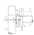
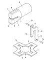
図1乃至図3に示す第1の実施の形態において、結合装置は、直角状態の配置で互いに結合せんとする鋼管の一方鋼管A(縦柱材)の外周に固定したフランジ部材1と、他方鋼管B(水平材)の端部に固定されたホルダー部材2と、このホルダー部材2内でフランジ部材1とホルダー部材2を締結する結合部材3との組み合わせからなり、フランジ部材1は、所定の厚みを有する矩形状金属板から、中央に鋼管Aへ外嵌して溶接する孔4を設けると共に、外周の四箇所を弧状に欠除して平面十字状に形成され、孔4の周囲で四箇所の位置に、等間隔で放射状の配置となる結合用の孔5が設けられている。
【0014】
他方鋼管Bの端部に溶接で固定されたホルダー部材2は、上下に細長い前壁6の両側に後方へ屈曲し、後端が他方鋼管Bと同径状となる略半円状の側壁7、7を折り曲げ連成し、該鋼管Bの端部に対して対向する両側壁7、7の後端を溶接し、両側壁7、7間の上下面が結合部材3を挿通するための開口8、8になっている。
【0015】
このホルダー部材2の前後方向の長さが、フランジ部材1の結合用の孔5を設けた部分の半径方向の長さよりも長く形成され、このホルダー部材2には、フランジ部材1の厚みに対して外嵌挿する切り欠き9が先端部から他方鋼管Bの軸方向に沿って設けられ、その先端壁6を一方鋼管Aの外周に当接させることができるように切り欠き9の深さが設定されている。上記切り欠き9をフランジ部材1に外嵌挿すれば、ホルダー部材2と他方鋼管Bは、該他方鋼管Bの軸心を中心とする回転が阻止されることになる。
【0016】
上記結合部材3は、フランジ部材1の結合用の孔5に対して上部から差し込む楔部10と、この楔部10の途中に設けた水平部11と、該水平部11の先端から直角に垂下してフランジ部材1の外周と他方鋼管Bの端部間に納まる杆状部12とで二又状に形成され、楔部10は下端に向けて狭幅となり、ホルダー部材2の前壁6の内面に当接させる前縁が垂直で結合用の孔5の端部に当接する後縁が傾斜縁になっている。なお、楔部10は図示のような下部狭幅形状以外に、ストレートな形状を採用してもよい。
【0017】
この楔部10の上端と杆状部12の下端に抜け止め用のピン13、14が固定され、ホルダー部材2内に挿入した結合部材3の楔部10を結合用の孔5に差し込んだ状態で、楔部10の上端がホルダー部材2の上面に突出すると共に、杆状部12の下端がホルダー部材2の下面から下方に突出することになり、ホルダー部材2の上面には該ホルダー部材2の先端寄りの一部にのみ楔部10が突出するだけであるので、図1に一点鎖線で示すように、ホルダー部材2の上面に被さるように足場板Cを載置することができるという利点がある。
【0018】
この発明の第1の実施の形態の結合装置は上記のような構成であり、一方の鋼管Aの途中に他方の鋼管Bを直角に結合するには、ホルダー部材2内に挿通した結合部材3を上昇位置に引き上げて保持した状態で、他方の鋼管Bの先端に固定したホルダー部材2の切り欠き9を、フランジ部材1の結合用の孔5を設けた部分に外周縁側から外嵌挿し、ホルダー部材2の先端壁6を一方の鋼管Aの外面に当接させると共に、ホルダー部材2をフランジ部材1に載置すれば、結合部材3の楔部10が丁度結合用の孔5の直上に臨むことになり、この状態で結合部材3を下降させて楔部10を結合用の孔5に圧入する。
【0019】
楔部10を結合用の孔5に圧入すると、傾斜縁による楔作用でホルダー部材2の先端壁6が一方の鋼管Aに向けて押され、該前壁6を楔部10と一方の鋼管Aで挟圧することにより、一方の鋼管Aに対して他方の鋼管Bを直角の配置で結合することができる。
【0020】
このようにして、一方の鋼管Aに対して四方から他方の鋼管Bを結合することができ、該鋼管Bの結合と一方の鋼管Aの継ぎ足しを組み合わせることにより、建築や土木工事の作業足場や支保工を構築することができる。
【0021】
上記結合状態で、図1に示すように、結合部材3はホルダー部材2の上面に対して、楔部10の上部が一部突出するだけであり、作業足場や支保工を構築した場合、水平材となる他方の鋼管B上に載置する足場板Cをホルダー部材2の上面に被る配置とすることができ、これにより、足場板Cの側縁を一方の鋼管Aに接近させることができ、作業足場や支保工の側面と足場板Cの側縁に生じる隙間を少なくすることができ、安全性の向上が図れる。
【0022】
また、結合を解くには、ホルダー部材2の下面から突出する杆状部12をハンマー等で叩き上げ、楔部10をフランジ部材1の結合用の孔5から抜き取り、ホルダー部材2をフランジ部材1から引き離せばよく、杆状部12が結合を解くための操作部になっている。
【0023】
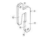
次に、図4乃至図6の第2の実施の形態は、結合部材の他の例を示し、杆状部12の楔部10に臨む側縁の途中に突部15を設けてその下端に係止段部16を形成し、ホルダー部材2の下部に開口8を跨ぐように設けた仮置き部17に対して係止段部16を係止することにより、結合部材3を楔部10の下端が切り欠き9よりも上方に位置する姿勢に保持することができることにより、結合の自動化と片手での結合の解除操作を可能にしている。
【0024】
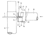
この例では、図5に示すように、一方の鋼管Aに対する他方の鋼管Bの結合前に、結合部材3を引き上げて係止段部16を仮置き部17に係止しておき、この状態でホルダー部材2の切り欠き9をフランジ部材1に対して嵌挿すると、嵌挿途中で突部15がフランジ部材1に当接し、ホルダー部材2と結合部材3に相対的な移動が生じて杆状部12が押し込まれ、この結果仮置き部17から係止段部16が外れ、結合部材3はホルダー部材2内を落下し、その時丁度楔部10の下端がフランジ部材1の結合用の孔5の真上に臨んでいるので、楔部10は自動的に結合用の孔5内に落ち込んで進入し、両鋼管AとBを自動的に結合することになる。
【0025】
上記結合状態で、ホルダー部材2の下部から杆状部12の下部が突出した状態になり、結合を解くときはこの杆状部12の下端を叩き上げ、結合部材3を上昇動させて楔部10を結合用の孔5から抜き出せば、係止段部16が仮置き部17に係合し、結合部材3の結合解除位置への操作が片手で行え、仮設足場や支保工の解体が安全に能率よく行える。
【0026】
また、図7乃至図9の第3の実施の形態は、フランジ部材1に設ける結合用の孔5の他の例を示し、フランジ部材1に等間隔の配置で設けられた結合用の孔の内、隣接する二つの孔は、結合部材3の楔部10が納まる長孔5aに形成され、残る二つの孔を外側広がりの扇形孔5bに形成したものである。
【0027】
長孔5aは楔部10の厚みが丁度納まる幅になっているので、この長孔5aを使用して結合した他方の鋼管Bは、一方の鋼管Aの半径方向に沿った配置となる。これに対し、扇形孔5bを使用して結合した他方の鋼管Bは、楔部10が扇形孔5aの幅方向に可動となるため、一方の鋼管Aの半径方向に対して角度を持たせた結合が可能となる。
【0028】
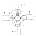
図8と図9はこのような角度を持たせた結合を組み合わせて構築した支保工の平面を示し、長孔5aを使用して四方に配置した一方の鋼管Aを他方の鋼管Bで結合することにより、正方形の基本枠を組み立て、その外側に扇形孔5bを使用して他方の鋼管Bを角度を持たせて結合することにより、支保工を円弧状や湾曲する構築物に沿う配置を可能にすることができる。
【0029】
なお、結合装置は、図示の場合、円形鋼管の結合例を示したが、角形鋼管の結合も同様の構造で行えると共に、結合装置の用途は鋼管を用いた支保工や足場のような構造物の構築だけでなく、鋼管の結合を必要とする部分に広く使用することができる。
【0030】
【発明の効果】
以上のように、この発明によると、一方鋼管の外周に固定したフランジ部材に結合用の孔を設け、他方鋼管の端部に固定したホルダー部材に、フランジ部材の厚みに対して外嵌挿する切り欠きを設け、このホルダー部材内でフランジ部材の結合用の孔に差し込む結合部材を、結合用の孔に対して差し込むことにより、ホルダー部材の先端壁を一方鋼管の外周面とで挟持するようにしたので、ホルダー部材内に結合部材を保持しておくことが可能となり、結合や解体時の操作性や作業性がよく、しかもホルダー部材内に結合部材を収めることで、全体の形状をコンパクトにすることができ、作業足場や支保工を構築した場合、ホルダー部材上に被さるように足場板を配置することができ、作業足場や支保工の側面と足場板の側縁間の隙間の発生を少なく、安全性の向上が図れることになる。
【0031】
また、結合部材の杆状部の側縁の途中に、ホルダー部材の下部に設けた仮置き部に対する係止段部を設けたので、結合作業時に結合部材の楔部を結合用の孔に自動的に嵌挿させることができ、結合の自動化により、結合作業の能率向上が図れる。
【0032】
更に、結合の解除が結合部材を叩き上げるだけでよいので、足場や支保工の解体が片手で行え、作業時の安全確保ができるので、解体作業の安全性向上が図れると共に、フランジ部材に設けた結合用の孔を扇形にしたので、一方鋼管に対して他方鋼管を角度をもって結合でき、曲線形状に対応できる支保工や足場を構築することができる。
【図面の簡単な説明】
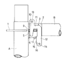
【図1】結合装置の第1の実施の形態を示す結合状態の縦断正面図
【図2】同上の平面図
【図3】結合装置の第1の実施の形態を示す分解斜視図
【図4】結合装置の第2の実施の形態を示す結合部材の斜視図
【図5】結合装置の第2の実施の形態を示す結合途中の縦断正面図
【図6】結合装置の第2の実施の形態を示す結合状態の縦断正面図
【図7】結合装置の第3の実施の形態を示すフランジ部材の平面図
【図8】結合装置の第3の実施の形態を示す結合状態の平面図
【図9】同上の要部を拡大した平面図
【符号の説明】
1 フランジ部材
2 ホルダー部材
3 結合部材
5 結合用の孔
6 先端壁
7 側壁
8 開口
9 切り欠き
10 楔部
12 杆状部
A 一方の鋼管
B 他方の鋼管[0001]
BACKGROUND OF THE INVENTION
The present invention relates to a coupling device used for constructing a temporary structure or the like by joining steel pipes at right angles.
[0002]
[Prior art]
For example, temporary structures such as work scaffolds and supporters using steel pipes are constructed by connecting steel pipes at right angles together with the addition of steel pipes. For this reason, a connecting device for connecting steel pipes at right angles Is required.
[0003]
Conventionally, a general joining device used for joining steel pipes at right angles is to fix a flange member provided with a hole for joining on the outer periphery of one of the steel pipes to be joined to each other. Fix the holder member with a notch that fits the flange member thickness at the end of the steel pipe, and connect the flange member from above the holder member with the holder member fitted on the flange member. Both steel pipes are connected at right angles by driving wedges into the holes.
[0004]
[Problems to be solved by the invention]
By the way, the coupling device as described above needs to completely remove the wedge to be driven into the coupling hole at the time of disassembly from the holder member, so that the wedge is separated from the holder member, and its management becomes troublesome. The operability and workability at the time of dismantling are poor, especially at the time of dismantling, the work to lift the lower end of the wedge and the work to lift the wedge must be done with both hands. There is a problem that it is not preferable from above.
[0005]
Also, in working scaffolds and support works, it is necessary to pass a scaffold plate between horizontal members to secure the passage. At this time, as much as possible between the side of the work scaffold or support work and the side edge of the scaffold plate. In the above-described conventional coupling device, the overall shape is enlarged, and the upper end of the wedge which is wide on the holder member protrudes from the holder member. Therefore, a wide gap is generated between the side surface of the work scaffold or the support work and the side edge of the scaffold plate, which is not preferable from the viewpoint of safety.
[0006]
Accordingly, an object of the present invention is to provide a coupling device that has good operability and workability at the time of coupling and dismantling, and is compact and can reduce the occurrence of gaps between the side surfaces of the work scaffolding and support work and the side edges of the scaffolding plate. It is to provide.
[0007]
[Means for Solving the Problems]
In order to solve the above-described problems, the invention of
[0009]
According to a second aspect of the present invention, in the first aspect of the invention, the coupling member is in a temporary placement posture in which a locking step portion provided in the hook-like portion is locked to the temporary placement portion, and a lower end of the wedge portion is a holder member. When the notch of the holder member is externally inserted into the flange member, the hook-shaped part comes into contact with the flange member and is pushed in, and the locking step part is removed from the temporary placement part and falls. The structure is such that the wedge portion falls into the coupling hole of the flange member and the coupling is automatically generated.
[0010]
According to a third aspect of the present invention, in the first or second aspect of the present invention, the coupling member is in a coupled state in which the wedge portion is inserted into the coupling hole of the flange member, and the lower end of the hook-shaped portion projects from the lower portion of the holder member. Thus, an operation unit for releasing the connection is adopted, and a configuration is adopted in which the connection can be released with one hand by pushing up the operation unit.
[0012]
DETAILED DESCRIPTION OF THE INVENTION
Hereinafter, embodiments of the present invention will be described with reference to the drawings.
[0013]
In the first embodiment shown in FIGS. 1 to 3, the coupling device includes a
[0014]
The
[0015]
The length of the
[0016]
The
[0017]
[0018]
The coupling device according to the first embodiment of the present invention is configured as described above. In order to couple the other steel pipe B at a right angle in the middle of one steel pipe A, the
[0019]
When the
[0020]
In this way, the other steel pipe B can be coupled from one side to the other steel pipe A. By combining the coupling of the steel pipe B and the addition of the one steel pipe A, a work scaffold for construction and civil engineering work Support construction can be built.
[0021]
In the above coupling state, as shown in FIG. 1, the
[0022]
Further, in order to release the coupling, the hook-
[0023]
Next, the second embodiment of FIGS. 4 to 6 shows another example of the coupling member, and a
[0024]
In this example, as shown in FIG. 5, before joining the other steel pipe B to one steel pipe A, the
[0025]
In the above coupled state, the lower part of the hook-
[0026]
7 to 9 show another example of the coupling holes 5 provided in the
[0027]
Since the
[0028]
FIG. 8 and FIG. 9 show the plane of the support construction constructed by combining the joints having such angles, and one steel pipe A arranged in four directions is joined by the other steel pipe B using the
[0029]
In addition, in the case of illustration, the coupling device has shown an example of coupling of circular steel pipes, but the square steel pipe can be coupled with the same structure, and the coupling device can be used for structures such as support works and scaffolds using the steel pipe. It can be widely used not only for construction but also for parts that require steel pipe connection.
[0030]
【The invention's effect】
As described above, according to the present invention, one of the flange members fixed to the outer periphery of the steel pipe is provided with a coupling hole, and the other end of the steel pipe is externally inserted with respect to the thickness of the flange member. A notch is provided, and the connecting member inserted into the connecting hole of the flange member in the holder member is inserted into the connecting hole so that the tip end wall of the holder member is held between the outer peripheral surface of the steel pipe. As a result, it is possible to hold the coupling member in the holder member, and the operability and workability at the time of coupling and disassembly are good, and the entire shape is compacted by housing the coupling member in the holder member. If a work scaffold or support is constructed, a scaffold plate can be placed over the holder member, creating a gap between the side of the work scaffold or support and the side edge of the scaffold plate. Less, so that it is possible to improve safety.
[0031]
In addition, a locking step for the temporary placement part provided at the lower part of the holder member is provided in the middle of the side edge of the hook-shaped part of the coupling member, so that the wedge part of the coupling member is automatically used as a coupling hole during the coupling operation. Thus, the efficiency of the joining work can be improved by automating the joining.
[0032]
In addition, since it is only necessary to lift the coupling member to release the coupling, the scaffolding and support work can be disassembled with one hand, ensuring safety during work, improving the safety of the dismantling work and providing it on the flange member. Since the connecting hole is fan-shaped, the other steel pipe can be connected to the one steel pipe at an angle, and a support and a scaffold that can cope with a curved shape can be constructed.
[Brief description of the drawings]
FIG. 1 is a longitudinal sectional front view showing a coupling device according to a first embodiment. FIG. 2 is a plan view of the same. FIG. 3 is an exploded perspective view showing the first embodiment of the coupling device. Fig. 5 is a perspective view of a coupling member showing a second embodiment of the coupling device. Fig. 5 is a longitudinal front view of the coupling device in the middle of coupling showing the second embodiment of the coupling device. FIG. 7 is a plan view of a flange member showing a third embodiment of the coupling device. FIG. 8 is a plan view of the coupling state showing a third embodiment of the coupling device. [Fig. 9] An enlarged plan view of the main part of the above.
DESCRIPTION OF
Claims (3)
前記結合部材が、結合用の孔に対して差し込む楔部と、フランジ部材の外周と他方鋼管の端部間に納まる杆状部とを二又状の配置で連成し、上記杆状部の楔部に臨む側縁の途中に、ホルダー部材の下部に設けた仮置き部に対する係止段部を設けて形成されていることを特徴とする結合装置。A flange member that is fixed to the outer periphery of one of the steel pipes to be connected to each other and provided with a hole for connection, and a notch that is fixed to the end of the other steel pipe and is fitted to the thickness of the flange member. A holder member which is provided along the axial direction of the other steel pipe from the tip portion, and whose tip wall can be brought into contact with the outer periphery of the one steel pipe; and a coupling member which is inserted into the coupling hole of the flange member in the holder member The holder member is formed by inserting the notch into the flange member to prevent rotation around the axis of the other steel pipe, and the coupling member is inserted into the coupling hole, In the coupling device formed to sandwich the tip wall of the holder member with the outer peripheral surface of the one steel pipe ,
The coupling member includes a wedge portion to be inserted into the coupling hole, and a hook-like portion that is fitted between the outer periphery of the flange member and the end of the other steel pipe in a bifurcated arrangement. A coupling device, wherein a locking step portion for a temporary placement portion provided at a lower portion of a holder member is provided in the middle of a side edge facing the wedge portion .
Priority Applications (1)
| Application Number | Priority Date | Filing Date | Title |
|---|---|---|---|
| JP23063099A JP4040802B2 (en) | 1999-08-17 | 1999-08-17 | Coupling device |
Applications Claiming Priority (1)
| Application Number | Priority Date | Filing Date | Title |
|---|---|---|---|
| JP23063099A JP4040802B2 (en) | 1999-08-17 | 1999-08-17 | Coupling device |
Publications (2)
| Publication Number | Publication Date |
|---|---|
| JP2001055830A JP2001055830A (en) | 2001-02-27 |
| JP4040802B2 true JP4040802B2 (en) | 2008-01-30 |
Family
ID=16910805
Family Applications (1)
| Application Number | Title | Priority Date | Filing Date |
|---|---|---|---|
| JP23063099A Expired - Lifetime JP4040802B2 (en) | 1999-08-17 | 1999-08-17 | Coupling device |
Country Status (1)
| Country | Link |
|---|---|
| JP (1) | JP4040802B2 (en) |
Cited By (2)
| Publication number | Priority date | Publication date | Assignee | Title |
|---|---|---|---|---|
| CN102235086A (en) * | 2010-04-28 | 2011-11-09 | 株式会社有弘维修 | Steel pipe combination device |
| CN103216722A (en) * | 2013-04-08 | 2013-07-24 | 常熟建工建设集团有限公司苏州分公司 | Novel universal change-over tube |
Families Citing this family (11)
| Publication number | Priority date | Publication date | Assignee | Title |
|---|---|---|---|---|
| KR100842111B1 (en) * | 2007-08-24 | 2008-06-30 | 에스앤피시스템(주) | A system support |
| JP5270147B2 (en) * | 2007-12-26 | 2013-08-21 | Krh株式会社 | Temporary scaffolding connection structure |
| CN103089002B (en) * | 2013-01-25 | 2015-06-10 | 开平市优赢金属制品有限公司 | Adaptor of scaffold |
| JP6395207B2 (en) * | 2014-07-15 | 2018-09-26 | 光洋機械産業株式会社 | Scaffolding connector and large assembly method and large paying method using the same |
| CN104372944A (en) * | 2014-10-27 | 2015-02-25 | 无锡市安捷脚手架有限公司 | Scaffold connecting element |
| JP6571054B2 (en) * | 2016-09-01 | 2019-09-04 | 日建リース工業株式会社 | Leading handrail for curved scaffolding |
| JP6796010B2 (en) * | 2017-03-14 | 2020-12-02 | 日建リース工業株式会社 | Wedge binding |
| JP7141658B2 (en) | 2018-07-31 | 2022-09-26 | 株式会社杉孝グループホールディングス | Wedge binding device in scaffolding |
| JP7306643B2 (en) | 2018-07-31 | 2023-07-11 | 株式会社杉孝グループホールディングス | Wedge binding device in scaffolding |
| JP7473396B2 (en) | 2020-05-25 | 2024-04-23 | アルインコ株式会社 | Wedge fastening device for scaffolding |
| JP7473395B2 (en) | 2020-05-25 | 2024-04-23 | アルインコ株式会社 | Wedge fastening device for scaffolding |
-
1999
- 1999-08-17 JP JP23063099A patent/JP4040802B2/en not_active Expired - Lifetime
Cited By (2)
| Publication number | Priority date | Publication date | Assignee | Title |
|---|---|---|---|---|
| CN102235086A (en) * | 2010-04-28 | 2011-11-09 | 株式会社有弘维修 | Steel pipe combination device |
| CN103216722A (en) * | 2013-04-08 | 2013-07-24 | 常熟建工建设集团有限公司苏州分公司 | Novel universal change-over tube |
Also Published As
| Publication number | Publication date |
|---|---|
| JP2001055830A (en) | 2001-02-27 |
Similar Documents
| Publication | Publication Date | Title |
|---|---|---|
| JP4040802B2 (en) | Coupling device | |
| JP2011231533A (en) | Steel pipe coupling device | |
| JP4753426B2 (en) | Steel pipe joints | |
| JP3851105B2 (en) | Construction method of temporary structure and handrail braiding used for this | |
| JP2007031987A (en) | Joining device | |
| JP2008202322A (en) | Handrail frame for scaffold | |
| JP2009299307A (en) | Unit type scaffolding and connecting implement | |
| JPWO2020100274A1 (en) | Clamp for binding scaffolding | |
| JP3051699B2 (en) | Scaffold braces and scaffold braid connectors | |
| KR20140062386A (en) | System scaffold | |
| JP3201716U (en) | Temporary scaffolding materials | |
| CN210887797U (en) | Assembled steel bar joint | |
| JP3051703B2 (en) | Handrail for scaffolding | |
| US5904875A (en) | Sloped wedge for use with concrete wall panel pins | |
| KR200487459Y1 (en) | System scaffolding diagonal brace locker | |
| JP2010255332A (en) | Baseboard material for temporary scaffolding | |
| JP2007092352A (en) | Temporary scaffold baseboard | |
| JP2020125661A (en) | Joint structure of underground continuous wall, and construction method of underground continuous wall | |
| JP6749618B2 (en) | Temporary scaffolding material | |
| JP2525362Y2 (en) | Joint structure of temporary structure | |
| JPH0893212A (en) | Trowel plate installation structure of rotary power trowel | |
| JP4058430B2 (en) | Structural material connection wedge | |
| JP7190225B1 (en) | receiving stage | |
| JP2005139635A (en) | Earth retaining timbering construction method and its frame body structure | |
| JP2005030156A (en) | Connection metal fitting for metal concrete mold in vertical and lateral direction |
Legal Events
| Date | Code | Title | Description |
|---|---|---|---|
| A621 | Written request for application examination |
Free format text: JAPANESE INTERMEDIATE CODE: A621 Effective date: 20060425 |
|
| A977 | Report on retrieval |
Free format text: JAPANESE INTERMEDIATE CODE: A971007 Effective date: 20070712 |
|
| A131 | Notification of reasons for refusal |
Free format text: JAPANESE INTERMEDIATE CODE: A131 Effective date: 20070717 |
|
| A521 | Written amendment |
Free format text: JAPANESE INTERMEDIATE CODE: A523 Effective date: 20070831 |
|
| TRDD | Decision of grant or rejection written | ||
| A01 | Written decision to grant a patent or to grant a registration (utility model) |
Free format text: JAPANESE INTERMEDIATE CODE: A01 Effective date: 20071016 |
|
| A61 | First payment of annual fees (during grant procedure) |
Free format text: JAPANESE INTERMEDIATE CODE: A61 Effective date: 20071108 |
|
| FPAY | Renewal fee payment (event date is renewal date of database) |
Free format text: PAYMENT UNTIL: 20101116 Year of fee payment: 3 |
|
| R150 | Certificate of patent or registration of utility model |
Ref document number: 4040802 Country of ref document: JP Free format text: JAPANESE INTERMEDIATE CODE: R150 Free format text: JAPANESE INTERMEDIATE CODE: R150 |
|
| FPAY | Renewal fee payment (event date is renewal date of database) |
Free format text: PAYMENT UNTIL: 20111116 Year of fee payment: 4 |
|
| R250 | Receipt of annual fees |
Free format text: JAPANESE INTERMEDIATE CODE: R250 |
|
| FPAY | Renewal fee payment (event date is renewal date of database) |
Free format text: PAYMENT UNTIL: 20121116 Year of fee payment: 5 |
|
| R250 | Receipt of annual fees |
Free format text: JAPANESE INTERMEDIATE CODE: R250 |
|
| FPAY | Renewal fee payment (event date is renewal date of database) |
Free format text: PAYMENT UNTIL: 20121116 Year of fee payment: 5 |
|
| FPAY | Renewal fee payment (event date is renewal date of database) |
Free format text: PAYMENT UNTIL: 20141116 Year of fee payment: 7 |
|
| R250 | Receipt of annual fees |
Free format text: JAPANESE INTERMEDIATE CODE: R250 |
|
| R250 | Receipt of annual fees |
Free format text: JAPANESE INTERMEDIATE CODE: R250 |
|
| R250 | Receipt of annual fees |
Free format text: JAPANESE INTERMEDIATE CODE: R250 |
|
| R250 | Receipt of annual fees |
Free format text: JAPANESE INTERMEDIATE CODE: R250 |
|
| R250 | Receipt of annual fees |
Free format text: JAPANESE INTERMEDIATE CODE: R250 |
|
| R250 | Receipt of annual fees |
Free format text: JAPANESE INTERMEDIATE CODE: R250 |
|
| EXPY | Cancellation because of completion of term |