JP4040733B2 - Denture polishing machine - Google Patents
Denture polishing machine Download PDFInfo
- Publication number
- JP4040733B2 JP4040733B2 JP35521497A JP35521497A JP4040733B2 JP 4040733 B2 JP4040733 B2 JP 4040733B2 JP 35521497 A JP35521497 A JP 35521497A JP 35521497 A JP35521497 A JP 35521497A JP 4040733 B2 JP4040733 B2 JP 4040733B2
- Authority
- JP
- Japan
- Prior art keywords
- box
- denture
- rotating shaft
- polishing machine
- oscillating
- Prior art date
- Legal status (The legal status is an assumption and is not a legal conclusion. Google has not performed a legal analysis and makes no representation as to the accuracy of the status listed.)
- Expired - Fee Related
Links
- 238000005498 polishing Methods 0.000 title claims description 18
- 230000005540 biological transmission Effects 0.000 claims description 11
- 229910052602 gypsum Inorganic materials 0.000 claims description 7
- 239000010440 gypsum Substances 0.000 claims description 7
- 239000003082 abrasive agent Substances 0.000 claims description 6
- 239000000463 material Substances 0.000 claims 1
- 238000000034 method Methods 0.000 description 2
- 238000007517 polishing process Methods 0.000 description 2
- XUIMIQQOPSSXEZ-UHFFFAOYSA-N Silicon Chemical compound [Si] XUIMIQQOPSSXEZ-UHFFFAOYSA-N 0.000 description 1
- 239000000853 adhesive Substances 0.000 description 1
- 230000001070 adhesive effect Effects 0.000 description 1
- 238000007664 blowing Methods 0.000 description 1
- 238000005266 casting Methods 0.000 description 1
- 230000000694 effects Effects 0.000 description 1
- 238000003754 machining Methods 0.000 description 1
- 239000000203 mixture Substances 0.000 description 1
- 230000000149 penetrating effect Effects 0.000 description 1
- 229910052710 silicon Inorganic materials 0.000 description 1
- 239000010703 silicon Substances 0.000 description 1
- 238000005245 sintering Methods 0.000 description 1
Images
Landscapes
- Dental Prosthetics (AREA)
Description
【0001】
【発明の属する技術分野】
本発明は、臨床的に印象取得された石膏歯形模型に基づいて形成された義歯の表面を鏡面に仕上げるための義歯用研磨加工機に関するものである。
【0002】
【従来の技術】
義歯には、インレー、歯冠、ブリッジ、部分床義歯、総義歯などがある。これらの義歯は、臨床的に印象取得された石膏歯形模型に基づいて、歯科技工士が、隣在歯、対合歯等との噛み合い状態をみながらその経験を元に、義歯の咬合面形状、コンタクトポイント、マージンライン等全体形状を決定し形成している。
【0003】
義歯の形成は、鋳造、焼結、NC制御による機械切削加工や型彫り加工等によって行われているが、いずれの方法で加工されたものであっても、口腔内で適合させるためには、その義歯の表面を鏡面状に仕上げることが要求されている。
【0004】
義歯の表面を鏡面状に仕上げる方法として、シリコンブロックやカーバイドバー、円筒状のワイヤブラシを回転させて研磨するものと、サンドブラスト等を吹き付けて研磨するものがある。
【0005】
【発明が解決しようとする課題】
いずれの仕上げ方法を行うにしても、義歯を1個づつ手作業で仕上げているため、研磨作業に時間がかかり作業性が悪いだけでなく、その仕上がり状態が作業者の熟練度に依存し、均一な仕上がりの義歯を安定的に供給することが困難であった。
【0006】
上記の事情に鑑み、本発明の目的は、加工成形された義歯の仕上げ作業を自動化し、作業性を向上させるとともに、均一な仕上がり状態の義歯を安定的に供給することを可能にする義歯用研磨加工機を提供することにある。
【0007】
【課題を解決するための手段】
上記の目的を達成するため、本出願の第1の発明においては、臨床的に印象取得された石膏歯形模型に基づいて形成された義歯の表面を鏡面に仕上げるための義歯用研磨加工機であって、水平軸を中心として回転可能な箱体と、該箱体の軸心部を貫通し、箱体とは別に回転可能に支持された回転軸と、一端に義歯を支持し、前記回転軸から箱体の内壁に向けて放射状に所定の間隔で着脱可能に配置された複数の揺動棒と、該揺動棒をその軸心を中心と往復揺動させる揺動手段と、前記箱体と回転軸を回転させたとき、その回転方向の所定の区間で揺動棒に支持された義歯が接触するように前記箱体内に投入された研磨材とを設けた。
【0008】
また、第2の発明においては、臨床的に印象取得された石膏歯形模型に基づいて形成された義歯の表面を鏡面に仕上げるための義歯用研磨加工機であって、水平軸を中心として回転可能な箱体と、該箱体の軸心部を貫通し、箱体とは別に回転可能に支持された中空の回転軸と、一端に義歯を支持し、前記回転軸から箱体の内壁に向けて放射状に所定の間隔で回転可能に配置された複数の揺動棒と、前記回転軸内で前記揺動棒の一端部に結合され、前記軸心方向に移動することにより揺動棒を揺動させる伝動軸と、前記箱体と回転軸を回転させたとき、その回転方向の所定の区間で揺動棒に支持された義歯が接触するように前記箱体内に投入された研磨材とを設けた。
【0009】
【発明の実施の形態】
以下、本発明の実施の形態を図面に基づいて説明する。
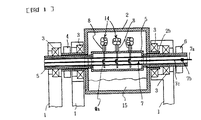
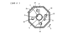
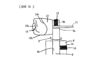
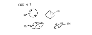
図1は、本発明による義歯用研磨加工機の正面断面図、図2は、図1のA−A断面図、図3は、図1における義歯取付け部の拡大図、図4は、研磨材の拡大図である。
【0010】
同図において、1は軸受用のブラケットで、図示しないベース上に所定の間隔で配置されている。2は軸直角断面が8角形に形成された箱体で、その一面に着脱可能な蓋2aが設けられ、両端には中空の軸2bが形成され、軸受3を介してブラケット1に回転可能に支持されている。4は伝動部材で、前記軸2bに固定され、図示しない電動機からの動力を箱体2に伝える。
【0011】
5は中空の回転軸で、前記軸2bおよび箱体2を回転可能に貫通し、軸受3を介してブラケット1に回転可能に支持されている。6は伝動部材で、前記回転軸5に固定され、図示しない電動機からの動力を回転軸5に伝える。
【0012】
7は伝動軸で、前記回転軸5の軸心部に配置され、図示しない駆動源に接続され摺動する摺動部7aと、回転継ぎ手7bを介して摺動部に接続され、摺動および回転可能な回転部7cで構成されている。
【0013】
8は支持軸で、一端が前記回転軸5に放射状に固定されている。また、支持軸8には、その軸心方向に貫通する穴8bが形成され、かつ、この穴8bと直交するようにねじ穴8cが形成されている。
【0014】
9は揺動棒で、一端が支持軸8の穴8bおよび回転軸5を回転可能に貫通し、回転軸5内部に位置する一端には、クランク部9aが形成されている。このクランク部9aと前記伝動軸7の回転部7cが図示しないリンクを介して接続され、伝動軸7の摺動により揺動棒9が揺動する。この揺動棒9の一端部には、揺動棒9の軸心と直交する穴9aと、軸心にねじ穴9bが形成されている。
【0015】
なお、前記揺動棒9は、ねじ穴8cに螺合する沈みボルト10で支持軸8に固定することもできる。
【0016】
13は支台歯で、臨床的に印象取得された石膏歯形模型あるいは副模型であり、ピン部11が一体に形成されている。前記ピン部11は、前記揺動棒9の穴9aに着脱可能に装着され、ねじ穴9bに螺合する沈みボルト12で固定される。ピン部11の一端に固定される。
【0017】
14は義歯(歯冠)で、支台歯13に接着剤で固定されている。義歯14は、咬合部14a、豊隆部14bおよびマージンライン部14cからなり、特に、マージンラインブ14cの精度が要求されている。
【0018】
15は研磨材で、箱体2内に適量投入されている。この研磨材15は、たとえば、図4に示すように、球形の研磨材15a、三角錐形の研磨材15b、平行多面体形状の研磨材15c、立方錐形の研磨材15dなどを混合して用いることにより、義歯14の咬合部14aに刻まれた裂溝内の研磨を同時に行うことができる。なお、研磨材の形状は上記のほか、さらに他の形状であってもよい。
【0019】
このような構成で、箱体2を矢印A方向に回転させると、箱体2内に投入された研磨材15は、箱体2とともに矢印A方向に移動し、その頂点がある高さに達すると矢印Bのように崩れ落ちる。これにより、研磨材15が撹拌され複数種の研磨材15a〜15dが均一に分布する。また、研磨材15同志が擦れ合うことにより研磨材15自身の目詰まりを防止することができる。
【0020】
同時に、義歯14を取り付けた回転軸5を矢印C(矢印Aと同じ方向)に回転させると、義歯14が研磨材15の中を通過して、義歯14と研磨材15が擦れ合うことにより義歯14の表面が研磨される。この時、取付け金具など義歯14の表面を覆うものがないので、段取り替えをすることなく全面を研磨することができる。また、回転軸5上の取付け位置にかかわりなく、義歯14を均一に研磨することができる。
【0021】
なお、回転軸5を矢印C方向とは逆方向に回転させると、義歯14と研磨材15の相対速度が大きくなり、研磨速度を向上させることができる。
【0022】
また、箱体2を高速回転させて、箱体2に投入された研磨材15をその遠心力により箱体2の内壁に押し広げ、ドーナツ状の研磨材層を形成させると同時に、回転軸5を箱体2とは逆方向に回転させ、義歯14研磨するようにしてもよい。
【0023】
さらに、伝動軸7を摺動させ揺動棒9を矢印D方向に揺動させることにより、影の部分に入るなど比較的研磨されにくい義歯14の豊隆部14bからマージンライン部14cまでの間を、直接研磨材15と擦れ合わせることができ、効率よく研磨することができる。したがって、短時間で義歯14の研磨を行うことができる。研磨終了後は、箱体2から支台歯13とともに義歯14を取り出し、副模型の支台歯13を砕いて義歯14を分離する。
【0024】
なお、上記の実施の形態においては、義歯14を回転軸5の軸心方向に複数列配置する形態について説明したが、義歯14の取付け位置を回転軸5の軸方向に少しづつ変位させて螺旋状に配置してもよい。
【0025】
【発明の効果】
以上述べたごとく、本発明によれば、加工成形された義歯の仕上げ作業を自動化し、作業性を向上させるとともに、臨床上実用的な面性状の均一な仕上がり状態の義歯を安定的に供給することを可能にする義歯用研磨加工機を提供することができる。
【図面の簡単な説明】
【図1】本発明による義歯用研磨加工機の正面断面図。
【図2】図1のA−A断面図。
【図3】図1における義歯取付け部の拡大図。
【図4】本発明による義歯用研磨加工機で使用する研磨材の形状を示す拡大図。
【符号の説明】
2…箱体、5…回転軸、7…伝動軸、9…揺動棒、14…義歯、15…研磨材。[0001]
BACKGROUND OF THE INVENTION
The present invention relates to a denture polishing machine for finishing the surface of a denture formed based on a gypsum tooth model obtained clinically to a mirror surface.
[0002]
[Prior art]
Dentures include inlays, crowns, bridges, partial dentures, and complete dentures. These dentures are based on a gypsum model that has been acquired clinically, and the dental technician examines the meshing condition with the adjacent teeth, counter teeth, etc. The overall shape, such as contact points and margin lines, is determined and formed.
[0003]
Dentures are formed by casting, sintering, NC cutting, machining, die-cutting, etc. It is required to finish the surface of the denture in a mirror shape.
[0004]
As a method of finishing the surface of the denture in a mirror surface, there are a method of polishing by rotating a silicon block, a carbide bar, and a cylindrical wire brush, and a method of polishing by blowing sandblast or the like.
[0005]
[Problems to be solved by the invention]
Whichever finishing method is used, the dentures are finished by hand one by one, so the polishing work takes time and the workability is not only poor, but the finished state depends on the skill level of the operator, It was difficult to stably supply a denture with a uniform finish.
[0006]
In view of the above circumstances, an object of the present invention is to provide a denture for automating finishing work of a processed denture, improving workability, and stably supplying a denture with a uniform finish. It is to provide a polishing machine.
[0007]
[Means for Solving the Problems]
In order to achieve the above object, in the first invention of the present application, there is provided a denture polishing machine for finishing the surface of a denture formed based on a gypsum model obtained clinically to a mirror surface. A box that is rotatable about a horizontal axis, a rotary shaft that passes through the axial center of the box and is rotatably supported separately from the box, and supports a denture at one end. A plurality of oscillating rods that are detachably arranged at predetermined intervals radially toward the inner wall of the box body, oscillating means for reciprocally oscillating the oscillating rod about the axis thereof, and the box body When the rotating shaft is rotated, an abrasive material introduced into the box is provided so that the denture supported by the swinging rod comes into contact in a predetermined section in the rotation direction.
[0008]
Further, in the second invention, a denture polishing machine for finishing the surface of a denture formed based on a gypsum tooth model obtained clinically to a mirror surface, which is rotatable about a horizontal axis And a hollow rotating shaft that is rotatably supported separately from the box body, supports a denture at one end, and faces the inner wall of the box body from the rotating shaft. Are coupled to one end of the swinging rod within the rotating shaft and moved in the axial direction to swing the swinging rod. A transmission shaft to be moved, and an abrasive put into the box so that the denture supported by the swing rod contacts in a predetermined section in the rotation direction when the box and the rotating shaft are rotated. Provided.
[0009]
DETAILED DESCRIPTION OF THE INVENTION
Hereinafter, embodiments of the present invention will be described with reference to the drawings.
1 is a front sectional view of a denture polishing machine according to the present invention, FIG. 2 is a sectional view taken along line AA of FIG. 1, FIG. 3 is an enlarged view of a denture mounting portion in FIG. 1, and FIG. FIG.
[0010]
In the figure,
[0011]
[0012]
[0013]
Reference numeral 8 denotes a support shaft, one end of which is fixed radially to the
[0014]
Reference numeral 9 denotes a swing rod, one end of which is rotatably penetrated through the
[0015]
The rocking bar 9 can be fixed to the support shaft 8 with a
[0016]
[0017]
[0018]
An abrasive 15 is put in an appropriate amount in the
[0019]
In such a configuration, when the
[0020]
At the same time, when the
[0021]
In addition, when the
[0022]
Further, the
[0023]
Further, by sliding the
[0024]
In the above-described embodiment, the description has been given of the form in which the
[0025]
【The invention's effect】
As described above, according to the present invention, the finishing operation of the processed denture is automated, the workability is improved, and a denture having a uniform finish with clinically practical surface properties is stably supplied. It is possible to provide a denture polishing machine that makes it possible.
[Brief description of the drawings]
FIG. 1 is a front sectional view of a denture polishing machine according to the present invention.
FIG. 2 is a cross-sectional view taken along line AA in FIG.
FIG. 3 is an enlarged view of a denture attachment part in FIG. 1;
FIG. 4 is an enlarged view showing the shape of an abrasive used in the denture polishing machine according to the present invention.
[Explanation of symbols]
DESCRIPTION OF
Claims (2)
前記箱体と回転軸を回転させたとき、その回転方向の全周もしくは所定の区間で揺動棒に支持された義歯が接触するように前記箱体内に投入された研磨材とを設けたことを特徴とする義歯用研磨加工機。A denture polishing machine for finishing the surface of a denture formed based on a gypsum model obtained clinically to a mirror surface, the box being rotatable about a horizontal axis, and the box A hollow rotating shaft that penetrates the shaft center and is supported so as to be rotatable separately from the box, supports a denture at one end, and can rotate radially from the rotating shaft toward the inner wall of the box at predetermined intervals. A plurality of oscillating rods, a transmission shaft arranged in the rotating shaft, and the transmission shaft and one end of the oscillating rod are coupled to reciprocate the transmission shaft in its axial direction. Link means for transmitting as a reciprocating rotational motion about the axis of the swinging rod, and when the box and the rotating shaft are rotated, the swinging rod is moved to the swinging rod in the entire circumference or in a predetermined section in the rotation direction. Abrasive material charged into the box is provided so that the supported dentures are in contact with each other. Denture polishing machine.
Priority Applications (1)
| Application Number | Priority Date | Filing Date | Title |
|---|---|---|---|
| JP35521497A JP4040733B2 (en) | 1997-12-24 | 1997-12-24 | Denture polishing machine |
Applications Claiming Priority (1)
| Application Number | Priority Date | Filing Date | Title |
|---|---|---|---|
| JP35521497A JP4040733B2 (en) | 1997-12-24 | 1997-12-24 | Denture polishing machine |
Publications (2)
| Publication Number | Publication Date |
|---|---|
| JPH11178841A JPH11178841A (en) | 1999-07-06 |
| JP4040733B2 true JP4040733B2 (en) | 2008-01-30 |
Family
ID=18442621
Family Applications (1)
| Application Number | Title | Priority Date | Filing Date |
|---|---|---|---|
| JP35521497A Expired - Fee Related JP4040733B2 (en) | 1997-12-24 | 1997-12-24 | Denture polishing machine |
Country Status (1)
| Country | Link |
|---|---|
| JP (1) | JP4040733B2 (en) |
Families Citing this family (2)
| Publication number | Priority date | Publication date | Assignee | Title |
|---|---|---|---|---|
| JP5225497B1 (en) * | 2012-10-29 | 2013-07-03 | 河本デンチャー歯研株式会社 | Dental prosthesis polishing equipment |
| CN115090451B (en) * | 2022-07-01 | 2023-07-14 | 深圳新致美精密齿研有限公司 | False tooth porcelain powder smearing device |
-
1997
- 1997-12-24 JP JP35521497A patent/JP4040733B2/en not_active Expired - Fee Related
Also Published As
| Publication number | Publication date |
|---|---|
| JPH11178841A (en) | 1999-07-06 |
Similar Documents
| Publication | Publication Date | Title |
|---|---|---|
| EP1825955B1 (en) | Oscillating grinding machine | |
| US4766704A (en) | Method and apparatus for the custom shaping of dental inlays, onlays, crowns, bridges and parts thereof | |
| AU2106800A (en) | Brush unit and toothbrush with brush unit | |
| KR101546971B1 (en) | Medical cutting tool manufacturing apparatus and method | |
| US6152813A (en) | Dresser and dressing apparatus | |
| JP4040733B2 (en) | Denture polishing machine | |
| KR20190111901A (en) | Methods and dental processing machines for manufacturing tooth restoration parts | |
| JP4061053B2 (en) | Electric sander | |
| JP5713328B1 (en) | Denture polishing equipment | |
| JPS6315947A (en) | Portable polishing apparatus for dental instrument | |
| JPS59182059A (en) | Polishing machine | |
| JPS5850827B2 (en) | Curved surface grinding device | |
| US2286599A (en) | Mortar and pestle | |
| JP2003048145A (en) | Orbital dental polishing equipment | |
| ITFI950066A1 (en) | IMPROVED HEAD FOR POLISHING MACHINES WITH OSCILLATING SECTOR-HOLDER ARMS | |
| JPS62199351A (en) | Polishing method for trimming and brushing device for trimming and polishing | |
| JPS6090668A (en) | Mirror surface polishing method | |
| JPS629859A (en) | Grinding and polishing method of ball | |
| US2557207A (en) | Polishing machine | |
| JP2517518Y2 (en) | Swivel rotary dresser | |
| JPS6232755Y2 (en) | ||
| EP0997113A2 (en) | Oscillating electric lathe for prosthodontics | |
| JP2001000246A (en) | Rotary brush making oscillatory rotational motion | |
| JP2863809B2 (en) | Dressing equipment | |
| JPS6316378Y2 (en) |
Legal Events
| Date | Code | Title | Description |
|---|---|---|---|
| A621 | Written request for application examination |
Free format text: JAPANESE INTERMEDIATE CODE: A621 Effective date: 20041206 |
|
| A977 | Report on retrieval |
Free format text: JAPANESE INTERMEDIATE CODE: A971007 Effective date: 20070306 |
|
| A131 | Notification of reasons for refusal |
Free format text: JAPANESE INTERMEDIATE CODE: A131 Effective date: 20070403 |
|
| A521 | Written amendment |
Free format text: JAPANESE INTERMEDIATE CODE: A523 Effective date: 20070604 |
|
| TRDD | Decision of grant or rejection written | ||
| A01 | Written decision to grant a patent or to grant a registration (utility model) |
Free format text: JAPANESE INTERMEDIATE CODE: A01 Effective date: 20071016 |
|
| A61 | First payment of annual fees (during grant procedure) |
Free format text: JAPANESE INTERMEDIATE CODE: A61 Effective date: 20071108 |
|
| FPAY | Renewal fee payment (event date is renewal date of database) |
Free format text: PAYMENT UNTIL: 20101116 Year of fee payment: 3 |
|
| R150 | Certificate of patent or registration of utility model |
Free format text: JAPANESE INTERMEDIATE CODE: R150 |
|
| FPAY | Renewal fee payment (event date is renewal date of database) |
Free format text: PAYMENT UNTIL: 20111116 Year of fee payment: 4 |
|
| FPAY | Renewal fee payment (event date is renewal date of database) |
Free format text: PAYMENT UNTIL: 20121116 Year of fee payment: 5 |
|
| FPAY | Renewal fee payment (event date is renewal date of database) |
Free format text: PAYMENT UNTIL: 20121116 Year of fee payment: 5 |
|
| FPAY | Renewal fee payment (event date is renewal date of database) |
Free format text: PAYMENT UNTIL: 20131116 Year of fee payment: 6 |
|
| LAPS | Cancellation because of no payment of annual fees |