JP4040727B2 - Temperature and humidity control device for fan coil unit - Google Patents
Temperature and humidity control device for fan coil unit Download PDFInfo
- Publication number
- JP4040727B2 JP4040727B2 JP28960297A JP28960297A JP4040727B2 JP 4040727 B2 JP4040727 B2 JP 4040727B2 JP 28960297 A JP28960297 A JP 28960297A JP 28960297 A JP28960297 A JP 28960297A JP 4040727 B2 JP4040727 B2 JP 4040727B2
- Authority
- JP
- Japan
- Prior art keywords
- temperature
- humidity
- air volume
- sensor unit
- blower
- Prior art date
- Legal status (The legal status is an assumption and is not a legal conclusion. Google has not performed a legal analysis and makes no representation as to the accuracy of the status listed.)
- Expired - Lifetime
Links
Images

Landscapes
- Air Conditioning Control Device (AREA)
Description
【0001】
【発明の属する技術分野】
本発明は、ファンコイルユニットの温湿度制御装置に関する。
【0002】
【従来の技術】
従来のファンコイルユニットの制御は、送風機を風量が一定の状態で運転させ、室内の温度のみを検知し、図5に示すように、室内の温度が設定温度範囲T1〜T2から外れると、熱交換器への熱源水の通水をバルブのオン・オフで対応しているものや、図示しないが、室内の温度のみを検知し、この温度が設定温度範囲から外れると、送風機の風量をオン・オフするもの等が知られている。
【0003】
【発明が解決しようとする課題】
前記した従来のファンコイルユニットの制御では、いずれも室内の温度の制御はできるが、湿度の制御まではできないので、細かな高品質の空気調和を行なうことができない。
【0004】
本発明は、このような不都合を解消することができる安価なファンコイルユニットの温湿度制御装置を提供することを課題とする。
【0005】
【課題を解決するための手段】
本発明は、前記の課題を解決するために、熱源水を通水させる熱交換器と、送風機とを備えるファンコイルユニットにおいて、室内の温度を検知する温度センサー部と湿度を検知する湿度センサー部とを有する温湿度センサーと、前記送風機の風量を制御する制御手段とを具備し、冷房時、冷房の設定温度とその下限温度との間に設定した風量変化動作温度に達するまでは前記送風機により風量を増大させて送風し、前記温度センサー部が前記風量変化動作温度を検知した時点で風量を低下して、低下した風量で前記温度センサー部が設定温度の下限温度又は前記湿度センサー部が設定湿度の下限湿度を検知するまで送風するように、前記制御手段により前記送風機の風量を制御することを特徴とする。
【0006】
本発明によれば、前記低下した風量により送風後、前記温度センサー部が設定温度の下限温度又は前記湿度センサー部が設定湿度の下限湿度を検知した時点で最小の風量に低下して、前記送風機により最小の風量で前記温度センサー部が設定温度又は前記湿度センサー部が設定湿度の上限湿度を検知するまで送風を続け、前記温度センサー部が設定温度の上限温度に達した場合は風量を増大して送風するように、前記制御手段により前記送風機の風量を制御する。
【0007】
【発明の実施の形態】
本発明の実施の形態を図面を参照して説明する。
【0008】
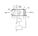
図1は、室内に設置されるファンコイルユニットの温湿度制御装置を示す。
【0009】
同図において、ファンコイルユニット1は、室内空気を取入れる取入れ口2a及び吹出し口2bを備えたケーシング2内に、その取入れ口2aに近接してフィルタ3と、その下流側に送風機4と、その下流側に熱源水を通水させる熱交換用コイル5とを備え、該ケーシング2の取入れ口2a近傍に室内の温度及び湿度を検知する温湿度センサー6を備えたものである。温湿度センサー6は、温度センサー部と湿度センサー部を備え、その各出力信号は、制御手段例えばコンピュータ7に入力し、該コンピュータ7は、前記各出力信号により送風機4を制御するようになっている。
【0010】
すなわち、コンピュータ7は、あらかじめ設定温度Ts、上限温度T1、下限温度T3(設定温度より例えば、1℃低い温度。)及び風量変化動作点温度T2(設定温度より例えば、0.5 ℃低い温度。)と、設定湿度Hs、上限湿度H1及び下限湿度H2と、送風機4の 100%の風量H、除湿量が最大になる風量L及び温度、湿度検知精度が維持できる最小風量LLが記憶されており、前記温湿度センサー6の出力信号により、送風機作動部8を介して送風機4を段階制御又は、無段階制御して、室内温度を設定温度Tsの近傍の上限温度T1 〜下限T3 内に保つと共に湿度を可能な限り好ましい状態、すなわち上限湿度H1〜下限湿度H2に保つように作動する。
【0011】
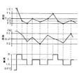
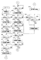
前記温湿度制御装置の作用を、図2の温湿度制御動作図及び図3のフローチャートにより、送風機4の段階制御の場合について更に詳細に説明する。
【0012】
電源をオンにすると、送風機4は100 %の風量Hで送風を開始し、コンピュータ7には、温湿度センサー6により検知された室内の温度及び湿度の出力信号が入力する(図3のステップS1)。コンピュータ7は、上限温度T1より高い室内温度から下限温度T3となるまでは温湿度センサー6の湿度センサー部に優先して温度センサー部の出力信号で作動するようになっており、温度が下降する過程で風量変化動作点温度T2を検知(S2)したとき、送風機4を除湿量が最大となる風量Lにし(S3)、温度が更に風量変化動作点温度T2より低下して下限温度T3を検知(S4)したとき、除湿検出精度が維持できる最小風量LLにする(S5)。最小風量LLにより湿度は設定湿度Hsに近付くが、それに伴い、温度が上昇し、温度が設定温度Tsになったことを検知したとき(S6)、温度センサー部の出力により、送風機4を除湿量が最大となる風量Lに制御する(S7)。温度が設定温度Ts未満で下限温度T3以上の温度範囲で安定した(例えば1分間)とき、コンピュータ7は、温度センサー部の出力による制御から湿度センサー部の出力による制御に変わり、湿度が下限湿度H2になったとき(S8)は、温度、湿度の検出精度が維持できる最小風量LLになるように送風機4を制御する(S9)。その後、温度が設定温度Tsになったとき(S10)は、除湿量が最大となる風量Lになるように送風機4を制御し(S11)、温度センサー部の出力信号により上限温度T1を検知したとき(S12)には、最大の風量Hになるように送風機4を制御する(S13)。この制御により温度が風量変化動作点温度T2に低下したとき(S14)、除湿量が最大となる風量Lになるように送風機4を制御し(S15)、温度が下限温度T3になったとき(S16)は、最小風量LLになるように送風機4を制御する(S17)。この制御により湿度が上限湿度H1に達したとき(S18)は、除湿量が最大となる風量Lに送風機4を制御する(S19)。そして、湿度が下限湿度H2になった場合は、湿度の検出精度が維持できる最小風量LLになるように送風機4を制御し(S20)、これより先に温度が下限温度T3になった場合にも、最小風量LLになるように送風機4を制御する(S21)。その後はステップ10に戻り、それ以降のステップの制御を行なう。すなわち、温度条件がT1〜T3を満足した後、湿度がH1〜H2になるように送風機4を制御する。
【0013】
尚、除湿量が最大となる風量Lは、試験にて決定するが、下記計算式
除湿量={(入口空気絶対温度)−(出口空気絶対温度)}×風量×空気の比重
から除湿値が最大となる風量を決める。
【0014】
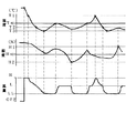
図4は、送風機4を無段階制御した場合の本発明実施の温湿度制御装置のフローチャートを示す。
【0015】
その作用は、前記段階制御の場合とほぼ同様であるので、説明を省略する。
【0016】
尚、暖房運転の場合は、温度のみを温湿度センサーで検知して風量の調節を行なう。
【0017】
【発明の効果】
本発明は、簡単な構成で、安価に室内の温度及び湿度の制御ができ、細かな高品質の空気調和を行なうことができるという効果を有する。
【図面の簡単な説明】
【図1】 本発明実施のファンコイルユニットの温湿度制御装置の線図。
【図2】 前記装置の段階制御の場合の温湿度制御動作図。
【図3】 前記装置の段階制御の場合のフローチャート。
【図4】 前記装置の非段階制御の場合の温湿度制御動作図。
【図5】 従来のファンコイルユニットの温湿度制御動作図。
【符号の説明】
1…ファンコイルユニット 4…送風機
5…熱交換用コイル 6…温湿度センサー
7…コンピュータ[0001]
BACKGROUND OF THE INVENTION
The present invention relates to a temperature / humidity control device for a fan coil unit.
[0002]
[Prior art]
In the conventional fan coil unit control, the fan is operated with a constant air volume, only the indoor temperature is detected, and as shown in FIG. 5, when the indoor temperature is out of the set temperature range T1 to T2, Heat source water flow to the exchanger is supported by turning the valve on and off, and although not shown, only the indoor temperature is detected, and if this temperature falls outside the set temperature range, the air volume of the blower is turned on. -Things that turn off are known.
[0003]
[Problems to be solved by the invention]
In any of the conventional fan coil unit controls described above, the indoor temperature can be controlled, but the humidity cannot be controlled, and therefore, fine high-quality air conditioning cannot be performed.
[0004]
An object of the present invention is to provide an inexpensive fan coil unit temperature / humidity control device capable of eliminating such inconveniences.
[0005]
[Means for Solving the Problems]
In order to solve the above-mentioned problems, the present invention provides a fan coil unit including a heat exchanger that allows heat source water to flow and a blower, a temperature sensor unit that detects an indoor temperature, and a humidity sensor unit that detects humidity. And a control means for controlling the air volume of the blower , and during the cooling, until the air flow change operating temperature set between the set temperature of the cooling and the lower limit temperature is reached by the blower The air volume is increased and the air is blown, and when the temperature sensor unit detects the air volume change operating temperature, the air volume is decreased, and the temperature sensor unit sets the lower limit temperature of the set temperature or the humidity sensor unit with the decreased air volume The air volume of the blower is controlled by the control means so that the air is blown until a lower limit humidity of humidity is detected .
[0006]
According to the present invention, after the air is blown by the reduced air volume, the temperature sensor unit decreases to the minimum air volume when the temperature sensor unit detects the lower limit temperature of the set temperature or the humidity sensor unit detects the lower limit humidity of the set humidity. The air flow is continued until the temperature sensor unit detects the set temperature or the humidity sensor unit detects the upper limit humidity of the set humidity with the minimum air volume.If the temperature sensor unit reaches the upper limit temperature of the set temperature, the air volume is increased. The air volume of the blower is controlled by the control means so that the air is blown.
[0007]
DETAILED DESCRIPTION OF THE INVENTION
Embodiments of the present invention will be described with reference to the drawings.
[0008]
FIG. 1 shows a temperature / humidity control device for a fan coil unit installed indoors.
[0009]
In the figure, a
[0010]
That is, the
[0011]
The operation of the temperature / humidity control device will be described in more detail with reference to the temperature / humidity control operation diagram of FIG. 2 and the flowchart of FIG.
[0012]
When the power is turned on, the
[0013]
Note that the air volume L that maximizes the dehumidification amount is determined by a test, but the following calculation formula dehumidification amount = {(inlet air absolute temperature) − (outlet air absolute temperature)} × air amount × the specific gravity of the air, Determine the maximum air volume.
[0014]
FIG. 4 shows a flowchart of the temperature and humidity control apparatus of the present invention when the
[0015]
Since the operation is almost the same as in the case of the step control, the description is omitted.
[0016]
In the case of heating operation, only the temperature is detected by the temperature / humidity sensor and the air volume is adjusted.
[0017]
【The invention's effect】
The present invention has an effect that the indoor temperature and humidity can be controlled at low cost with a simple configuration, and fine high-quality air conditioning can be performed.
[Brief description of the drawings]
FIG. 1 is a diagram of a temperature / humidity control device for a fan coil unit according to the present invention.
FIG. 2 is a temperature / humidity control operation diagram in the case of stage control of the apparatus.
FIG. 3 is a flowchart in the case of stage control of the apparatus.
FIG. 4 is a temperature and humidity control operation diagram in the case of non-stage control of the apparatus.
FIG. 5 is a temperature / humidity control operation diagram of a conventional fan coil unit.
[Explanation of symbols]
DESCRIPTION OF
Claims (2)
Priority Applications (1)
| Application Number | Priority Date | Filing Date | Title |
|---|---|---|---|
| JP28960297A JP4040727B2 (en) | 1997-10-22 | 1997-10-22 | Temperature and humidity control device for fan coil unit |
Applications Claiming Priority (1)
| Application Number | Priority Date | Filing Date | Title |
|---|---|---|---|
| JP28960297A JP4040727B2 (en) | 1997-10-22 | 1997-10-22 | Temperature and humidity control device for fan coil unit |
Publications (2)
| Publication Number | Publication Date |
|---|---|
| JPH11125451A JPH11125451A (en) | 1999-05-11 |
| JP4040727B2 true JP4040727B2 (en) | 2008-01-30 |
Family
ID=17745370
Family Applications (1)
| Application Number | Title | Priority Date | Filing Date |
|---|---|---|---|
| JP28960297A Expired - Lifetime JP4040727B2 (en) | 1997-10-22 | 1997-10-22 | Temperature and humidity control device for fan coil unit |
Country Status (1)
| Country | Link |
|---|---|
| JP (1) | JP4040727B2 (en) |
Families Citing this family (3)
| Publication number | Priority date | Publication date | Assignee | Title |
|---|---|---|---|---|
| CN102141267B (en) * | 2010-12-23 | 2016-03-30 | 卢娜 | A kind of constant temperature and humidity main frame |
| CN110260590A (en) * | 2019-06-04 | 2019-09-20 | 凯盛光伏材料有限公司 | A kind of air cooling equipment cooling with water |
| CN114294790B (en) * | 2021-12-28 | 2024-01-02 | 中山市爱美泰电器有限公司 | Control method of water source type dehumidifying temperature regulator |
-
1997
- 1997-10-22 JP JP28960297A patent/JP4040727B2/en not_active Expired - Lifetime
Also Published As
| Publication number | Publication date |
|---|---|
| JPH11125451A (en) | 1999-05-11 |
Similar Documents
| Publication | Publication Date | Title |
|---|---|---|
| JPH11287502A5 (en) | ||
| JPH10197028A (en) | Air conditioner | |
| JP4040727B2 (en) | Temperature and humidity control device for fan coil unit | |
| JPS622225B2 (en) | ||
| JPH0436535A (en) | Method of operating indoor fan of air conditioner | |
| JP4710138B2 (en) | Air conditioner with humidification function | |
| JP3143195B2 (en) | Air conditioner | |
| JP2755003B2 (en) | Duct air conditioner | |
| KR19980033782A (en) | Discharge airflow control device and method for air conditioner | |
| JP2776111B2 (en) | Dehumidifier | |
| JPH0593542A (en) | Air conditioner | |
| JPH04110552A (en) | Air conditioner | |
| JPH08276720A (en) | Air conditioner for vehicle | |
| JPH0526487A (en) | Device for automatically operating ventilating fan of simultaneous intake-exhaust type | |
| JP3641119B2 (en) | Air conditioner operation control device | |
| JP2512750B2 (en) | Air-conditioning air flow controller | |
| JPH0351658A (en) | Air conditioner | |
| JPS6284250A (en) | Air conditioner | |
| JP2636553B2 (en) | Air conditioner | |
| JPH04297741A (en) | Air conditioner | |
| JPH04131655A (en) | Centralized type air conditioning apparatus | |
| JPH05133560A (en) | Air conditioner test room | |
| JPH0351657A (en) | Air conditioner | |
| JPH01302057A (en) | Operation control device for air conditioner | |
| JPS6054564B2 (en) | air conditioner |
Legal Events
| Date | Code | Title | Description |
|---|---|---|---|
| A621 | Written request for application examination |
Free format text: JAPANESE INTERMEDIATE CODE: A621 Effective date: 20040701 |
|
| A625 | Written request for application examination (by other person) |
Free format text: JAPANESE INTERMEDIATE CODE: A625 Effective date: 20040701 |
|
| A131 | Notification of reasons for refusal |
Free format text: JAPANESE INTERMEDIATE CODE: A131 Effective date: 20061017 |
|
| A131 | Notification of reasons for refusal |
Free format text: JAPANESE INTERMEDIATE CODE: A131 Effective date: 20070417 |
|
| A521 | Written amendment |
Free format text: JAPANESE INTERMEDIATE CODE: A821 Effective date: 20070517 |
|
| RD02 | Notification of acceptance of power of attorney |
Free format text: JAPANESE INTERMEDIATE CODE: A7422 Effective date: 20070517 |
|
| A521 | Written amendment |
Free format text: JAPANESE INTERMEDIATE CODE: A523 Effective date: 20070607 |
|
| A521 | Written amendment |
Free format text: JAPANESE INTERMEDIATE CODE: A523 Effective date: 20070726 |
|
| TRDD | Decision of grant or rejection written | ||
| A01 | Written decision to grant a patent or to grant a registration (utility model) |
Free format text: JAPANESE INTERMEDIATE CODE: A01 Effective date: 20071023 |
|
| A61 | First payment of annual fees (during grant procedure) |
Free format text: JAPANESE INTERMEDIATE CODE: A61 Effective date: 20071108 |
|
| FPAY | Renewal fee payment (event date is renewal date of database) |
Free format text: PAYMENT UNTIL: 20101116 Year of fee payment: 3 |
|
| R150 | Certificate of patent or registration of utility model |
Free format text: JAPANESE INTERMEDIATE CODE: R150 |
|
| FPAY | Renewal fee payment (event date is renewal date of database) |
Free format text: PAYMENT UNTIL: 20111116 Year of fee payment: 4 |
|
| FPAY | Renewal fee payment (event date is renewal date of database) |
Free format text: PAYMENT UNTIL: 20121116 Year of fee payment: 5 |
|
| FPAY | Renewal fee payment (event date is renewal date of database) |
Free format text: PAYMENT UNTIL: 20131116 Year of fee payment: 6 |
|
| R250 | Receipt of annual fees |
Free format text: JAPANESE INTERMEDIATE CODE: R250 |
|
| R250 | Receipt of annual fees |
Free format text: JAPANESE INTERMEDIATE CODE: R250 |
|
| R250 | Receipt of annual fees |
Free format text: JAPANESE INTERMEDIATE CODE: R250 |
|
| EXPY | Cancellation because of completion of term |