JP4040701B2 - Stereolithography method and apparatus - Google Patents
Stereolithography method and apparatus Download PDFInfo
- Publication number
- JP4040701B2 JP4040701B2 JP18060295A JP18060295A JP4040701B2 JP 4040701 B2 JP4040701 B2 JP 4040701B2 JP 18060295 A JP18060295 A JP 18060295A JP 18060295 A JP18060295 A JP 18060295A JP 4040701 B2 JP4040701 B2 JP 4040701B2
- Authority
- JP
- Japan
- Prior art keywords
- data
- model
- casting
- shape
- condition
- Prior art date
- Legal status (The legal status is an assumption and is not a legal conclusion. Google has not performed a legal analysis and makes no representation as to the accuracy of the status listed.)
- Expired - Fee Related
Links
Images
Classifications
-
- Y—GENERAL TAGGING OF NEW TECHNOLOGICAL DEVELOPMENTS; GENERAL TAGGING OF CROSS-SECTIONAL TECHNOLOGIES SPANNING OVER SEVERAL SECTIONS OF THE IPC; TECHNICAL SUBJECTS COVERED BY FORMER USPC CROSS-REFERENCE ART COLLECTIONS [XRACs] AND DIGESTS
- Y02—TECHNOLOGIES OR APPLICATIONS FOR MITIGATION OR ADAPTATION AGAINST CLIMATE CHANGE
- Y02P—CLIMATE CHANGE MITIGATION TECHNOLOGIES IN THE PRODUCTION OR PROCESSING OF GOODS
- Y02P10/00—Technologies related to metal processing
- Y02P10/25—Process efficiency
Landscapes
- Molds, Cores, And Manufacturing Methods Thereof (AREA)
- Heating, Cooling, Or Curing Plastics Or The Like In General (AREA)
Description
【0001】
【産業上の利用分野】
本発明は光造形方法および装置に関し、特に湯口、湯道およびゲートを付加した鋳造用の消失モデルを形成するための光造形方法および装置に関する。
【0002】
【従来の技術】
従来から、消失モデルを用いてその周囲に鋳型を成型し、次いで該鋳型を加熱して消失モデルを消失させ、その後該鋳型を焼成することにより、内部に空隙を備えた鋳型を形成する技術が知られている。この鋳型に、溶融した金属を注湯し、その後冷却して凝固させると、前記消失モデルと同一の形状の金属製品を得ることができる。
【0003】
前記消失モデルを形成するために、まずマスターモデルを切削等の手法により作成し、次いで該マスターモデルの複製を作成する装置が開発されている。また、真空注型装置を用いて、ワックス製の消失模型を作ることが知られている。さらに、近年では、モデルの図面寸法を基にして3次元画像モデルを形成し、このモデルを基に光ビームを作成し、液状樹脂に該光ビームを照射して光硬化させ、立体的な樹脂モデルを形成する3次元光モデル形成システムが開発されている。
【0004】
【発明が解決しようとする課題】
この3次元光モデル形成システムを用いると、極めて容易にかつ短期間に、マスタモデルを形成することができる。しかしながら、マスタモデルは、単に図面上から複製された製品形状に過ぎず、鋳造を目的としたものではない。したがって、該マスタモデルを鋳造に使用できるようにするためには、湯口、湯道、ゲート等の鋳造補助部分を別途に作成し、該マスタモデルに接続して鋳型を作成しなければならず、生産性が悪いという問題があった。また、このようにして作成した鋳型に溶融された金属を注湯して金属製品を作成すると、該金属製品に巣や引けが発生し、歩留まりが悪くなるという問題があった。
【0005】
本発明の目的は、前記した問題点に鑑み、鋳造に適したマスタモデルを容易に作成することができる光造形方法および装置を提供することにある。他の目的は、金属製品に巣やひけを発生させない鋳型を作成するためのマスタモデルを容易に作成することができる光造形方法および装置を提供することにある。
【0006】
【課題を解決するための手段】
そこで発明者は、前記課題を解決すべく、鋭意、研究を重ねた結果、その発明を、鋳型に消失によりキャビテイを形成するための消失モデルを光造形する方法において、
光造形すべき消失モデルの形状を示す数値データを入力するステップと、
前記消失モデルに付加する湯道及びゲ−トの形状、長さ、断面積、モデルに接続する位置等を含む鋳造補助部分について選択した鋳造補助条件のデータを入力するステップと、
前記消失モデルの形状を示す数値データと前記鋳造補助条件のデータとをもって前記消失モデルの形状と該モデルに付加する鋳造補助部分の形状からなる3次元画像データに基づいて3次元的に作図して表示するステップと、
鋳造金属の種類、溶湯の凝固する温度、凝固速度、熱伝導率等の属性を示すデータを入力するステップと、
使用する鋳型の種類、その熱伝導率等の属性を示すデータを入力するステップと、
鋳造金属の種類、溶湯の凝固する温度、凝固速度、熱伝導率等に関して入力したデ−タと前記使用する鋳型の種類その熱伝導率等に関して入力したデータに基いて鋳造時の鋳型温度、溶湯温度等を含む鋳造条件のデータを入力するステップと
前記鋳造金属の溶湯を湯口から供給し前記湯道及びゲートを通って前記消失モデル形状に充満させて溶湯が凝固する過程をシミュレートして前記3次元画像データと鋳造条件のデータに基いて溶湯の凝固解析を行うステップと、
凝固解析の結果、鋳造品に巣又は引けが生じるか否かを判断し鋳造品に巣または引けが生じている場合にはその旨を表示させるステップと、
巣又は引けが生じている場合には、前記入力した鋳造補助条件のデータを変更し、必要に応じて鋳造条件を補正して凝固解析を繰り返すステップと、
凝固解析の結果、鋳造品に巣又は引けが生じない鋳造補助条件と鋳造条件が確認されると、消失モデル形状の数値データに鋳造補助条件データを付加したデータを最終モデルデータ記憶手段に記憶するステップと、
該最終モデルデータ記憶手段に記憶されたデータに基き、光造形装置を使用して消失材料で構成される液状樹脂に光ビームを照射して光硬化させて消失モデル形状に鋳造補助部分が付加された立体的な樹脂モデルを造形するステップ
とからなることを特徴とする光造形方法とすることにより課題を解決した。
また、本発明は、
鋳型に消失によりキャビテイを形成するための消失モデルを光造形する装置において、
造形すべき消失モデルの形状を示す数値データを入力するためのモデル形状数値入力手段を設けること、
前記モデルに付加する湯道及びゲ−トの形状、長さ、断面積、モデルに接続する位置等を含む鋳造補助部分の鋳造補助条件のデータを選択して入力するための鋳造補助条件設定手段を設けること、
前記モデル形状数値入力手段と鋳造補助条件設定手段により入力されたデ−タをもって前記消失モデルの形状と該モデルに付加する鋳造補助部分の形状を3次元画像として表示するための3次元画像デ−タ生成手段を設けること、
該3次元画像データ生成手段により生成された3次元画像データに基づき3次元的に作図して表示する画像表示手段を設けること、
鋳造金属の種類、溶湯の凝固する温度、凝固速度、熱伝導率等の属性を示すデータを入力するための金属種類入力手段を設けること、
使用する鋳型の種類(石膏等)、その熱伝導率等の属性を示すデータを入力するための鋳型条件入力手段を設けること、前記金属種類入力手段と鋳型条件入力手段により入力されたデ−タに基いて可能となる鋳造時の鋳型温度、溶湯温度等を含む鋳造条件を設定する鋳造条件のデータを入力する手段を設けること、
前記鋳造金属の溶湯を湯口から供給し前記湯道及びゲ−トを通って前記消失モデル形状に充満させて溶湯が凝固する過程をシミュレートして前記3次元画像デ−タと鋳造条件のデータに基いて溶湯の凝固解析を行うための凝固解析手段を設けること、
凝固解析の結果、鋳造品に巣又は引けが生じているか否かを判断し鋳造品に巣または引けが生じている場合にはその旨を表示させる判定手段を設けること、
巣又は引けが生じている場合には、前記入力した鋳造補助条件のデータを変更し、必要に応じて鋳造条件を補正して凝固解析を繰り返すための補正手段を設けること、
凝固解析の結果、鋳造品に巣又は引けが生じない鋳造補助条件と鋳造条件が確認されると、消失モデル形状の数値データに該鋳造補助条件データを付加したデ−タを記憶する最終モデルデ−タ記憶手段を設けることで、
該最終モデルデータ記憶手段に記憶されたデ−タに基き、消失材料で構成される液状樹脂に光ビームを照射して光硬化させて消失モデル形状に鋳造補助部分が付加された立体的な樹脂モデルを造形するようにしたことを特徴とする光造形する装置とすることにより課題を解決した。
【0007】
【作用】
本発明によれば、モデル形状と鋳造時に使用する湯道およびゲートとを組合せてモデリングする。また、鋳造に使用する金属と、鋳型の種類を選択し、これらに基づいて可能となる鋳造条件を設定する。次いで、前記モデリングした3次元の画像データと鋳造条件とにより、溶融金属の凝固解析を行い、鋳造品となるモデル形状内に巣または引け等の不良点が発生するか否かの判定を行う。不良点が発生している場合には前記湯道またはゲートを補正して再度凝固解析を行う。以上の結果、前記モデル形状内に巣または引け等の不良点が発生しなくなると、該モデル形状に湯道およびゲートを付加して、光造形を行う。
【0008】
【実施例】
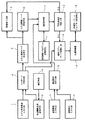
以下に図面を参照して、本発明を詳細に説明する。図1は、本発明の光造形装置の一実施例の概要を示すブロック図である。図において、モデル形状数値入力手段1は例えば消失モデルの2次元6面図の数値データからなるモデル形状数値データを入力する装置からなり、6面図数値データを記憶したフロッピディスク等の磁気媒体等から構成されている。また、コンピュータCADを用いて、2次元6面図数値データから3次元座標軸データを作成し、これをモデル形状数値データとして使用するようにしてもよい。画像表示手段2は液晶パネル、CRT等からなり、前記モデル形状数値入力手段1から入力されたモデル形状あるいは後述する湯口、湯道、ゲート等の鋳造補助部分等を3次元的に作図して表示する。したがって、オペレータは、前記モデル形状数値入力手段1から入力されたモデル形状およびこれに接続された湯口、湯道、ゲート等の鋳造補助部分等を3次元的に目視で確認することができる。
【0009】
鋳造補助条件設定手段3はオペレータが任意の湯道およびゲートを選択することができるように、複数の湯道、ゲート等の鋳造補助部分を用意している。湯道およびゲートは、それぞれ、用意されているものの中から任意の形状の物を選択し、その高さ、断面積、体積等の任意の数値を選択することができる。また、モデル形状に付けるゲートの位置を自由に変更することができる。
【0010】
入力データ記憶手段4では、前記モデル形状数値入力手段1から入力されたデータと鋳造補助条件設定手段3から入力されたデータとを記憶する。3次元画像データ生成手段5ではこれらのデータを合成し、3次元画像データを生成する。該3次元画像データは3次元画像データ記憶手段6に記憶されると共に、画像表示装置2に表示される。
【0011】
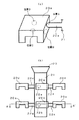
上記の構成の動作の概要を、図2、図3を参照して説明する。図2(a) はモデル形状およびこれに接続されたゲート22aの斜視図を示す。モデル形状数値入力手段1からはモデル形状20aの6面図データが入力される。また、鋳造補助条件設定手段3からはゲート22aの形状(例えば、断面が丸、四角、三角等)、その長さ、断面積、モデル形状20aに接続するゲート位置(A、B、C、D等)の選択等がなされる。また、湯道21の形状、長さ、断面積等の選択が行われる。これらのデータは、入力データ記憶手段4に記憶され、3次元画像データ生成手段5にて3次元画像データに組立てられる。図2(b) は該3次元画像データの一例の概念図である。また、図3は図2(b) のA−A´線断面図である。
【0012】
次に、図1の金属種類入力手段7からは湯口23から供給する鋳造金属(すなわち溶湯)の種類、溶湯の凝固する温度、凝固速度、熱伝導率等の属性が入力される。また、鋳型条件入力手段8からは、使用する鋳型の種類(例えば、石膏等)、その熱伝導率等が入力される。金属種類入力手段7および鋳型条件入力手段8から入力されたデータは鋳型条件設定手段9に送られ、該鋳型条件設定手段9にて鋳造条件が設定される。例えば、鋳造する際の鋳型温度、溶湯温度等の鋳造条件が設定される。
【0013】
凝固解析部10は、前記3次元画像データ記憶手段6に記憶されたモデル形状20a、20b、20c、…、ゲート22a、22b、22c、…、および湯道21からなる3次元画像の湯口23から、鋳型条件設定手段9で設定された鋳造金属からなる溶湯を供給し、該溶湯を湯道21、ゲート22a、22b、22c、…を通って各モデル形状20a、20b、20c、…に充満させ、該鋳造金属が凝固する過程をシミュレートする。凝固解析に使用する制御プログラムは、凝固解析プログラム記憶手段11に記憶されている。鋳造工程では、高温の溶湯から鋳型へ熱が移動し、該溶湯は冷却される。この時、液相から固相への相変態が起こり、潜熱が放出され、また密度変化(凝固収縮)が起こる。この密度変化が、鋳造品に巣や引けを発生する直接の原因となる。凝固解析は、このような凝固現象を数式化し、コンピュータによって凝固速度や、巣および引けが発生する位置を予測する。なお、凝固解析の手法は周知であるので、説明を省略する。
【0014】
不良点検出判定手段11は、前記凝固解析部10の解析結果から、モデル20a〜20fの内部、すなわち鋳造品に、巣または引けが生じているか否かの判断をする。そして、鋳造品に巣または引けが生じている場合には、その旨が前記画像表示手段2に表示される。そこで、オペレータは、補正手段16を用いて、前記鋳造補助条件設定手段3から入力されたゲートをモデル形状に付ける位置を変更したり、その断面積を変えたり、ゲートの種類を変える等の補正を行い、また必要に応じて、鋳造条件設定手段9において設定される溶湯温度や鋳型温度等を補正して、再度凝固解析を行う。この凝固解析によっても、なお鋳造品に、巣または引けが生じる場合には、再度前記鋳造補助条件や鋳造条件を変更して、凝固解析を行う。
【0015】
該凝固解析により、モデル20a〜20fの内部、すなわち鋳造品に、巣または引けが生じない鋳造補助条件や鋳造条件が見つかると、最終モデルデータ記憶手段12に前記入力データ記憶手段4に記憶されているデータ、すなわち図2(b) に示されているようなモデル形状に鋳造補助条件データ、すなわちゲートおよび湯道を付加したデータが記憶される。光造形装置13は、該最終モデルデータ記憶手段12に記憶されたデータに基づいて、液状樹脂に該光ビームを照射して光硬化させ、立体的な樹脂モデルを形成する。この樹脂モデルは、ワックス、プラスチック等の熱により消失する材料から構成されているので、その後の工程で該樹脂モデルを用いて鋳型が形成された場合、この鋳型を使用すれば、鋳造物に巣や引けのない製品を作ることができるようになることは明らかであろう。
【0016】
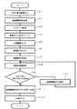
次に、本実施例の動作を、図4のフローチャートを参照して説明する。
【0017】
ステップS1では、モデル形状数値入力手段1からモデル形状を数値入力し、ステップS2では、鋳造補助条件設定手段3からモデルに接続するゲート、湯道等の指定が行われる。ステップS3では、ステップS1で入力されたモデル形状の数値データ、およびステップS2で指定された鋳造補助条件を入力データ記憶手段4に記憶する。ステップS4では、3次元画像データ生成手段5が3次元モデルに前記ゲートおよび湯道を付加して、画像モデルのモデリングをする。このモデリングの結果は、画像表示手段2に表示されると共に3次元画像データ記憶手段6に記憶される。なお、オペレータは該画像表示手段2に表示された画像モデルを見ながら、鋳造補助条件設定手段3を操作することにより、モデルに付加するゲートの形状、大きさ、付加する位置等を自由に変更することができる。
【0018】
ステップS5では、金属種類入力手段7により、鋳造に用いる金属の種類とそれの属性が入力される。すなわち、鋳造金属(溶湯)の種類、溶湯の凝固する温度、凝固速度、熱伝導率等の属性が入力される。ステップS6では、鋳型条件入力手段8から鋳型条件、すなわち使用する鋳型の種類、その熱伝導率等が入力される。ステップS7では、鋳造条件設定手段9はステップS5、S6の設定に基づいて可能となる鋳型温度、溶湯温度等の鋳造条件を設定する。ステップS8では、凝固解析部10は3次元画像データ記憶手段6に記憶されているモデル、ゲート、湯道からなる3次元画像データ、例えば図2(b) のような3次元画像データと、前記金属種類入力手段7、鋳型条件入力手段8および鋳造条件設定手段9によって入力および設定されたデータに基づいて、溶湯の凝固解析を行う。この際、凝固解析部10は凝固解析プログラム記憶手段11に格納されている凝固解析プログラムにより、制御される。
【0019】
ステップS9では、溶湯の凝固解析が終了すると、不良点検出判定手段12にて、モデル内に巣または引けが発生しているか否かの判断がなされる。この判断が肯定の場合には、ステップS10に進んで鋳造補助条件設定手段3から鋳造補助条件の補正が行われる。そして、再びステップS8に戻って溶湯の凝固解析が試みられる。以上の動作が繰り返し行われ、ステップS9の判断が否定になると、すなわちモデル内に巣または引けが発生しないことが確認されると、ステップS11に進んで、最終モデルデータ記憶手段13に、鋳造補助条件をモデル形状に付加したデータが記憶される。ステップS12では、光造形システムプログラム記憶手段15に記憶された光造形システムプログラムを駆使し、かつ前記最終モデルデータ記憶手段13に記憶されているデータを用いて、光造形装置14は光造形を実行する。この結果、例えば図2(b) に示されているような形状の消失材料から構成されたモデルが作成される。このモデルを利用して鋳型を構成した後実際に溶融金属を湯道に流して鋳造品を作成すると、巣や引けのない鋳造品を作成することができ、生産性と信頼性の向上を図ることができるようになる。また、歩留まり良く、鋳造品を製造することができるようになる。
【0020】
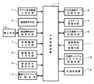
次に、本発明の光造形装置のハード構成を図5のブロック図に示す。図中の図1と同一の符号は、同一物を示す。補正手段16は、鋳造補助条件を補正するために操作される。中央演算装置17は、モデル形状数値入力手段1、鋳造補助条件設定手段3、金属種類入力手段7、鋳型条件入力手段8および鋳造条件設定手段9から入力されたデータを用い、かつ凝固解析プログラム記憶手段11に記憶されている凝固解析プログラムを駆使して、凝固解析のシミュレートを行う。また、最終モデルデータ記憶手段13に記憶されたデータを用い、かつ光造形システムプログラム記憶手段15に記憶されている光造形システムプログラムを駆使して、光造形装置14により光造形を行う。
【0021】
【発明の効果】
本発明によれば、鋳造物に相当するモデルに、ゲートおよび湯道を付加してモデリングをし、凝固解析によりモデル形状内に巣または引け等の不良点が発生しないことを確認した後、光造形を行うようにしているので、鋳造に適したマスタモデルを容易に作成することができる。また、このマスタモデルを用いると、巣やひけのない鋳造製品を歩留まり良く得ることのできる鋳型を容易に作成することができる。
【図面の簡単な説明】
【図1】 本発明の光造形装置の一実施例の構成を説明するためのブロック図である。
【図2】 (a) はモデル形状の一例を示す斜視図、(b) はモデリングした3次元画像の一例を示す概念図である。
【図3】 図2(b) のA−A´線断面図である。
【図4】 本発明の一実施例の動作を説明するためのフローチャートである。
【図5】 本発明のハード構成を示すブロック図である。
【符号の説明】
1…モデル形状数値入力手段、2…画像表示手段、3…鋳造補助条件設定手段、4…入力データ記憶手段、5…3次元画像データ生成手段、6…3次元画像データ記憶手段、7…金属種類入力手段、8…鋳型条件入力手段、9…鋳型条件設定手段、10…凝固解析部、11…凝固解析プログラム記憶手段、12…最終モデルデータ記憶手段、13…光造形装置。[0001]
[Industrial application fields]
The present invention relates to an optical modeling method and apparatus, and more particularly to an optical modeling method and apparatus for forming a casting disappearance model to which a gate, a runner, and a gate are added.
[0002]
[Prior art]
Conventionally, there has been a technique for forming a mold with a void inside by molding a mold around the disappearance model, then heating the mold to disappear the disappearance model, and then firing the mold. Are known. When molten metal is poured into the mold and then cooled and solidified, a metal product having the same shape as the disappearance model can be obtained.
[0003]
In order to form the disappearance model, an apparatus has been developed that first creates a master model by a technique such as cutting, and then creates a duplicate of the master model. It is also known to make a disappearance model made of wax using a vacuum casting apparatus. Further, in recent years, a three-dimensional image model is formed on the basis of the drawing dimensions of the model, a light beam is created based on the model, and the liquid resin is irradiated with the light beam to be photocured to form a three-dimensional resin. A three-dimensional optical model forming system for forming a model has been developed.
[0004]
[Problems to be solved by the invention]
By using this three-dimensional optical model forming system, a master model can be formed very easily and in a short time. However, the master model is merely a product shape reproduced from the drawing, and is not intended for casting. Therefore, in order to be able to use the master model for casting, a casting auxiliary part such as a gate, a runner, and a gate must be separately created and connected to the master model to create a mold, There was a problem of poor productivity. Further, when a metal product is prepared by pouring molten metal into the mold prepared in this way, there is a problem that nests and shrinkage occur in the metal product, resulting in poor yield.
[0005]
In view of the above-described problems, an object of the present invention is to provide an optical modeling method and apparatus that can easily create a master model suitable for casting. Another object is to provide an optical modeling method and apparatus capable of easily creating a master model for creating a mold that does not cause nests or sink marks in a metal product.
[0006]
[Means for Solving the Problems]
Therefore, the inventor, as a result of earnest and research, to solve the above problems, the present invention, in the method of optical modeling the disappearance model for forming the cavity by disappearance in the mold,
Inputting numerical data indicating the shape of the disappearance model to be stereolithographically;
Inputting data of casting auxiliary conditions selected for the casting auxiliary part including the shape, length, cross-sectional area, position to be connected to the model, and the like of the runner and gate to be added to the disappearance model;
Three-dimensional drawing based on the three-dimensional image data comprising the shape of the disappearance model and the shape of the casting auxiliary portion added to the model with numerical data indicating the shape of the disappearance model and data of the auxiliary casting condition Steps to display;
Inputting data indicating attributes such as the type of cast metal, the temperature at which the molten metal solidifies, the solidification rate, and the thermal conductivity;
Inputting data indicating attributes such as the type of mold to be used and its thermal conductivity;
Based on the data entered regarding the type of cast metal, the temperature at which the molten metal solidifies, the solidification rate, the thermal conductivity, etc., and the type of mold used, the data regarding the thermal conductivity, etc., the mold temperature at the time of casting, the molten metal A step of inputting data of casting conditions including temperature and the like, and a process of supplying molten metal of the cast metal from the gate and filling the disappeared model shape through the runner and the gate to simulate the solidification of the molten metal Performing solidification analysis of the molten metal based on the three-dimensional image data and casting condition data;
As a result of solidification analysis, it is determined whether or not a nest or shrinkage occurs in the cast product, and if there is a nest or shrinkage in the cast product, a step of displaying that fact;
If nest or shrinkage has occurred, changing the input casting auxiliary condition data, correcting the casting conditions as necessary, repeating the solidification analysis; and
As a result of the solidification analysis, when the casting auxiliary condition and casting condition in which no casting or shrinkage occurs in the cast product are confirmed, data obtained by adding the casting auxiliary condition data to the numerical data of the disappeared model shape is stored in the final model data storage means. Steps,
Based on the data stored in the final model data storage means, a casting auxiliary part is added to the lost model shape by irradiating a light beam to the liquid resin composed of the lost material using an optical modeling apparatus and photocuring it. The problem was solved by using an optical modeling method characterized by comprising a step of modeling a three-dimensional resin model.
The present invention also provides:
In the device for optical modeling of the disappearance model for forming cavities by disappearance in the mold,
Providing a model shape numerical value input means for inputting numerical data indicating the shape of the disappearing model to be modeled;
Casting auxiliary condition setting means for selecting and inputting the casting auxiliary condition data of the casting auxiliary part including the shape, length, cross-sectional area, position connected to the model, and the like of the runner and gate added to the model Providing
Three-dimensional image data for displaying the shape of the disappearance model and the shape of the casting auxiliary portion added to the model as data in the form inputted by the model shape numerical value input means and the casting auxiliary condition setting means. Providing data generation means,
Providing image display means for drawing and displaying three-dimensionally based on the three-dimensional image data generated by the three-dimensional image data generating means;
Providing a metal type input means for inputting data indicating attributes such as the type of cast metal, the temperature at which the molten metal solidifies, the solidification rate, and the thermal conductivity;
Provided with mold condition input means for inputting data indicating attributes such as the type of mold to be used (gypsum, etc.) and its thermal conductivity, the data input by the metal type input means and the mold condition input means Providing means for inputting casting condition data for setting casting conditions including mold temperature, molten metal temperature, etc. at the time of casting that is possible based on
3D image data and casting condition data are simulated by supplying a molten metal of the cast metal from the gate and filling the disappeared model shape through the runner and gate to solidify the molten metal. Providing solidification analysis means for performing solidification analysis of molten metal based on
As a result of solidification analysis, it is determined whether or not a nest or a shrinkage has occurred in the cast product, and if there is a nest or a shrinkage in the cast product, a determination means for displaying the fact is provided.
If a nest or shrinkage has occurred, change the input casting auxiliary condition data, and if necessary, provide a correction means for correcting the casting condition and repeating the solidification analysis,
As a result of solidification analysis, when the casting auxiliary condition and casting condition in which no casting or shrinkage occurs in the cast product are confirmed, the final model data for storing data obtained by adding the casting auxiliary condition data to the numerical data of the disappeared model shape is stored. Data storage means,
Based on the data stored in the final model data storage means, a three-dimensional resin in which a liquid resin composed of a disappearing material is irradiated with a light beam and light-cured to add a casting auxiliary part to the disappearing model shape The problem was solved by using an optical modeling apparatus characterized by modeling a model.
[0007]
[Action]
According to the present invention, modeling is performed by combining the model shape with the runner and gate used during casting. Moreover, the metal used for casting and the kind of casting_mold | template are selected, and the casting conditions made possible based on these are set. Next, solidification analysis of the molten metal is performed based on the modeled three-dimensional image data and casting conditions, and it is determined whether or not defects such as nests or shrinkage occur in the model shape to be a cast product. If a defective point has occurred, the runner or gate is corrected and solidification analysis is performed again. As a result, when no defects such as nests or shrinkage occur in the model shape, a runner and a gate are added to the model shape to perform optical modeling.
[0008]
【Example】
Hereinafter, the present invention will be described in detail with reference to the drawings. FIG. 1 is a block diagram showing an outline of an embodiment of the optical modeling apparatus of the present invention. In the figure, the model shape numerical value input means 1 comprises, for example, a device for inputting model shape numerical data consisting of numerical data of a two-dimensional six-sided view of the disappearance model, and a magnetic medium such as a floppy disk storing the six-sided numerical value data. It is composed of Alternatively, three-dimensional coordinate axis data may be created from two-dimensional hexahedral numerical data using a computer CAD and used as model shape numerical data. The image display means 2 comprises a liquid crystal panel, CRT, etc., and displays the model shape input from the model shape numerical value input means 1 or a casting auxiliary part such as a gate, a runner, and a gate to be described later in a three-dimensional manner. To do. Therefore, the operator can visually confirm the model shape inputted from the model shape numerical value input means 1 and casting auxiliary parts such as the gate, runner, and gate connected to the model shape in three dimensions.
[0009]
The casting auxiliary condition setting means 3 has a plurality of casting auxiliary parts such as a plurality of runners and gates so that the operator can select any runner and gate. As for the runner and the gate, an object having an arbitrary shape can be selected from those prepared, and arbitrary numerical values such as a height, a cross-sectional area, and a volume can be selected. Further, the position of the gate attached to the model shape can be freely changed.
[0010]
The input data storage means 4 stores the data input from the model shape numerical value input means 1 and the data input from the casting auxiliary condition setting means 3. The three-dimensional image data generating means 5 combines these data to generate three-dimensional image data. The three-dimensional image data is stored in the three-dimensional image data storage means 6 and displayed on the
[0011]
An outline of the operation of the above configuration will be described with reference to FIGS. FIG. 2A shows a perspective view of the model shape and the gate 22a connected thereto. From the model shape numerical value input means 1, 6-face drawing data of the model shape 20 a is input. Further, from the casting auxiliary condition setting means 3, the shape of the gate 22a (for example, round, square, triangular, etc.), its length, cross-sectional area, and the gate position (A, B, C, D connected to the model shape 20a) Etc.) is selected. In addition, the shape, length, cross-sectional area, etc. of the
[0012]
Next, attributes such as the type of cast metal (that is, molten metal) supplied from the
[0013]
The
[0014]
The defective point detection determination means 11 determines from the analysis result of the
[0015]
When a casting auxiliary condition or casting condition that does not cause nest or shrinkage is found in the models 20a to 20f, that is, in the cast product, the final model data storage means 12 stores the input data storage means 4 in the final model data storage means 12. Data, i.e., data obtained by adding casting auxiliary condition data, i.e., a gate and a runner to the model shape as shown in FIG. 2 (b). The
[0016]
Next, the operation of this embodiment will be described with reference to the flowchart of FIG.
[0017]
In step S1, a model shape is numerically input from the model shape numerical value input means 1, and in step S2, a gate, a runner, etc. connected to the model are designated from the casting auxiliary condition setting means 3. In step S3, the numerical data of the model shape input in step S1 and the casting auxiliary conditions specified in step S2 are stored in the input
[0018]
In step S5, the metal type input means 7 inputs the type of metal used for casting and its attributes. That is, attributes such as the type of cast metal (molten metal), the temperature at which the molten metal solidifies, the solidification rate, and the thermal conductivity are input. In step S6, the mold conditions are input from the mold condition input means 8, that is, the type of mold to be used, its thermal conductivity, and the like. In step S7, the casting condition setting means 9 sets casting conditions such as mold temperature and molten metal temperature that are possible based on the settings in steps S5 and S6. In step S8, the
[0019]
In step S9, when the solidification analysis of the molten metal is completed, the defective point
[0020]
Next, the hardware configuration of the optical modeling apparatus of the present invention is shown in the block diagram of FIG. The same reference numerals in FIG. 1 as those in FIG. The correction means 16 is operated to correct the casting auxiliary conditions. The
[0021]
【The invention's effect】
According to the present invention, a model corresponding to a casting is modeled by adding a gate and a runner, and it is confirmed by solidification analysis that no defects such as nests or shrinkage occur in the model shape. Since modeling is performed, a master model suitable for casting can be easily created. Further, when this master model is used, a mold capable of obtaining a cast product free of nests or sink marks with a high yield can be easily created.
[Brief description of the drawings]
FIG. 1 is a block diagram for explaining a configuration of an embodiment of an optical modeling apparatus of the present invention.
2A is a perspective view illustrating an example of a model shape, and FIG. 2B is a conceptual diagram illustrating an example of a modeled three-dimensional image.
FIG. 3 is a cross-sectional view taken along line AA ′ of FIG.
FIG. 4 is a flowchart for explaining the operation of the embodiment of the present invention.
FIG. 5 is a block diagram showing a hardware configuration of the present invention.
[Explanation of symbols]
DESCRIPTION OF
Claims (2)
光造形すべき消失モデルの形状を示す数値データを入力するステップと、
前記消失モデルに付加する湯道及びゲ−トの形状、長さ、断面積、モデルに接続する位置等を含む鋳造補助部分について選択した鋳造補助条件のデータを入力するステップと、
前記消失モデルの形状を示す数値データと前記鋳造補助条件のデータとをもって前記消失モデルの形状と該モデルに付加する鋳造補助部分の形状からなる3次元画像データに基づいて3次元的に作図して表示するステップと、
鋳造金属の種類、溶湯の凝固する温度、凝固速度、熱伝導率等の属性を示すデータを入力するステップと、
使用する鋳型の種類、その熱伝導率等の属性を示すデータを入力するステップと、
鋳造金属の種類、溶湯の凝固する温度、凝固速度、熱伝導率等に関して入力したデ−タと前記使用する鋳型の種類その熱伝導率等に関して入力したデータに基いて鋳造時の鋳型温度、溶湯温度等を含む鋳造条件のデータを入力するステップと、
前記鋳造金属の溶湯を湯口から供給し前記湯道及びゲートを通って前記消失モデル形状に充満させて溶湯が凝固する過程をシミュレートして前記3次元画像データと鋳造条件のデータに基いて溶湯の凝固解析を行うステップと、
凝固解析の結果、鋳造品に巣又は引けが生じるか否かを判断し鋳造品に巣または引けが生じている場合にはその旨を表示させるステップと、
巣又は引けが生じている場合には、前記入力した鋳造補助条件のデータを変更し、必要に応じて鋳造条件を補正して凝固解析を繰り返すステップと、
凝固解析の結果、鋳造品に巣又は引けが生じない鋳造補助条件と鋳造条件が確認されると、消失モデル形状の数値データに鋳造補助条件データを付加したデータを最終モデルデータ記憶手段に記憶するステップと、
該最終モデルデータ記憶手段に記憶されたデータに基き、光造形装置を使用して消失材料で構成される液状樹脂に光ビームを照射して光硬化させて消失モデル形状に鋳造補助部分が付加された立体的な樹脂モデルを造形するステップ
とからなることを特徴とする光造形方法。In the method of optical modeling the disappearance model for forming cavities by disappearance in the mold,
Inputting numerical data indicating the shape of the disappearance model to be stereolithographically;
Inputting data of casting auxiliary conditions selected for the casting auxiliary part including the shape, length, cross-sectional area, position to be connected to the model, and the like of the runner and gate to be added to the disappearance model;
And three-dimensionally plotting and on the basis of the three-dimensional image data composed of the shape of the casting auxiliary part with a data of the numerical data and the casting auxiliary condition indicating a shape of the lost model is added to the shape and the model of the lost model Steps to display;
Inputting data indicating attributes such as the type of cast metal, the temperature at which the molten metal solidifies, the solidification rate, and the thermal conductivity;
Inputting data indicating attributes such as the type of mold to be used and its thermal conductivity;
Based on the data entered regarding the type of cast metal, the temperature at which the molten metal solidifies, the solidification rate, the thermal conductivity, etc., and the type of mold used, the data regarding the thermal conductivity, etc., the mold temperature at the time of casting, the molten metal Inputting data of casting conditions including temperature, etc .;
The molten metal of the cast metal is supplied from the gate and filled into the disappeared model shape through the runner and the gate to simulate the solidification of the molten metal, and based on the three-dimensional image data and the casting condition data. Performing a solidification analysis of
As a result of solidification analysis, it is determined whether or not a nest or shrinkage occurs in the cast product, and if there is a nest or shrinkage in the cast product, a step of displaying that fact;
If nest or shrinkage has occurred, changing the input casting auxiliary condition data , correcting the casting conditions as necessary, repeating the solidification analysis; and
As a result of the solidification analysis, when the casting auxiliary condition and casting condition in which no casting or shrinkage occurs in the cast product are confirmed, data obtained by adding the casting auxiliary condition data to the numerical data of the disappeared model shape is stored in the final model data storage means. Steps,
Based on the data stored in the final model data storage means , a casting auxiliary part is added to the lost model shape by irradiating a light beam to the liquid resin composed of the lost material using an optical modeling apparatus and photocuring it. And a step of modeling a three - dimensional resin model.
造形すべき消失モデルの形状を示す数値データを入力するためのモデル形状数値入力手段を設けること、
前記モデルに付加する湯道及びゲ−トの形状、長さ、断面積、モデルに接続する位置等を含む鋳造補助部分の鋳造補助条件のデータを選択して入力するための鋳造補助条件設定手段を設けること、
前記モデル形状数値入力手段と鋳造補助条件設定手段により入力されたデ−タをもって前記消失モデルの形状と該モデルに付加する鋳造補助部分の形状を3次元画像として表示するための3次元画像デ−タ生成手段を設けること、
該3次元画像データ生成手段により生成された3次元画像データに基づき3次元的に作図して表示する画像表示手段を設けること、
鋳造金属の種類、溶湯の凝固する温度、凝固速度、熱伝導率等の属性を示すデータを入力するための金属種類入力手段を設けること、
使用する鋳型の種類(石膏等)、その熱伝導率等の属性を示すデータを入力するための鋳型条件入力手段を設けること、
前記金属種類入力手段と鋳型条件入力手段により入力されたデ−タに基いて可能となる鋳造時の鋳型温度、溶湯温度等を含む鋳造条件を設定する鋳造条件のデータを入力する手段を設けること、
前記鋳造金属の溶湯を湯口から供給し前記湯道及びゲ−トを通って前記消失モデル形状に充満させて溶湯が凝固する過程をシミュレートして前記3次元画像デ−タと鋳造条件のデ ータに基いて溶湯の凝固解析を行うための凝固解析手段を設けること、
凝固解析の結果、鋳造品に巣又は引けが生じているか否かを判断し鋳造品に巣または引けが生じている場合にはその旨を表示させる判定手段を設けること、
巣又は引けが生じている場合には、前記入力した鋳造補助条件のデータを変更し、必要に応じて鋳造条件を補正して凝固解析を繰り返すための補正手段を設けること、
凝固解析の結果、鋳造品に巣又は引けが生じない鋳造補助条件と鋳造条件が確認されると、消失モデル形状の数値データに該鋳造補助条件データを付加したデ−タを記憶する最終モデルデ−タ記憶手段を設けることで、
該最終モデルデータ記憶手段に記憶されたデ−タに基き、消失材料で構成される液状樹脂に光ビームを照射して光硬化させて消失モデル形状に鋳造補助部分が付加された立体的な樹脂モデルを造形するようにしたことを特徴とする光造形する装置。In the device for optical modeling of the disappearance model for forming cavities by disappearance in the mold,
Providing a model shape numerical value input means for inputting numerical data indicating the shape of the disappearing model to be modeled;
Casting auxiliary condition setting means for selecting and inputting the casting auxiliary condition data of the casting auxiliary part including the shape, length, cross-sectional area, position connected to the model, and the like of the runner and gate added to the model Providing
Three-dimensional image data for displaying the shape of the disappearance model and the shape of the casting auxiliary portion added to the model as data in the form inputted by the model shape numerical value input means and the casting auxiliary condition setting means. Providing data generation means,
Providing image display means for drawing and displaying three-dimensionally based on the three-dimensional image data generated by the three-dimensional image data generating means;
Providing a metal type input means for inputting data indicating attributes such as the type of cast metal, the temperature at which the molten metal solidifies, the solidification rate, and the thermal conductivity;
Providing mold condition input means to input data indicating attributes such as the type of mold used (gypsum, etc.) and its thermal conductivity,
There is provided means for inputting casting condition data for setting casting conditions including casting mold temperature, molten metal temperature and the like, which can be performed based on data input by the metal type input means and the mold condition input means. ,
A process of supplying the molten metal of the cast metal from the gate and filling the disappeared model shape through the runner and the gate to solidify the molten metal to simulate the three-dimensional image data and the casting condition data . Providing solidification analysis means for performing solidification analysis of the molten metal based on the data;
As a result of solidification analysis, it is determined whether or not a nest or a shrinkage has occurred in the cast product, and if there is a nest or a shrinkage in the cast product, a determination means for displaying the fact is provided.
If a nest or shrinkage has occurred, change the input casting auxiliary condition data , and if necessary, provide a correction means for correcting the casting condition and repeating the solidification analysis,
As a result of solidification analysis, when the casting auxiliary condition and casting condition in which no casting or shrinkage occurs in the cast product are confirmed, the final model data for storing data obtained by adding the casting auxiliary condition data to the numerical data of the disappeared model shape is stored. by providing the data storage means,
Based on the data stored in the final model data storage means, a three - dimensional resin in which a liquid resin composed of a disappearing material is irradiated with a light beam and light-cured to add a casting auxiliary part to the disappearing model shape An optical modeling apparatus characterized by modeling a model.
Priority Applications (1)
| Application Number | Priority Date | Filing Date | Title |
|---|---|---|---|
| JP18060295A JP4040701B2 (en) | 1994-09-17 | 1995-06-26 | Stereolithography method and apparatus |
Applications Claiming Priority (3)
| Application Number | Priority Date | Filing Date | Title |
|---|---|---|---|
| JP6-248592 | 1994-09-17 | ||
| JP24859294 | 1994-09-17 | ||
| JP18060295A JP4040701B2 (en) | 1994-09-17 | 1995-06-26 | Stereolithography method and apparatus |
Publications (2)
| Publication Number | Publication Date |
|---|---|
| JPH08132533A JPH08132533A (en) | 1996-05-28 |
| JP4040701B2 true JP4040701B2 (en) | 2008-01-30 |
Family
ID=26500061
Family Applications (1)
| Application Number | Title | Priority Date | Filing Date |
|---|---|---|---|
| JP18060295A Expired - Fee Related JP4040701B2 (en) | 1994-09-17 | 1995-06-26 | Stereolithography method and apparatus |
Country Status (1)
| Country | Link |
|---|---|
| JP (1) | JP4040701B2 (en) |
Families Citing this family (1)
| Publication number | Priority date | Publication date | Assignee | Title |
|---|---|---|---|---|
| TWI462973B (en) * | 2007-04-20 | 2014-12-01 | Heritage Res Group | Polymer-modified asphalt compositions |
-
1995
- 1995-06-26 JP JP18060295A patent/JP4040701B2/en not_active Expired - Fee Related
Also Published As
| Publication number | Publication date |
|---|---|
| JPH08132533A (en) | 1996-05-28 |
Similar Documents
| Publication | Publication Date | Title |
|---|---|---|
| US6691764B2 (en) | Method for producing casting molds | |
| KR100199546B1 (en) | Design device of injection molding mold and design method | |
| JP2698520B2 (en) | How to make a casting plan for a breathable mold | |
| HK1001677A1 (en) | Reduced stereolithographic part distortion through isolation | |
| US20170333980A1 (en) | Method of investment casting using additive manufacturing | |
| KR102047273B1 (en) | Method and apparatus for producing wax model containing precision casting cores | |
| EP1385103B1 (en) | Simulation of fluid flow and structural analysis within thin walled three dimensional geometries | |
| JP4040701B2 (en) | Stereolithography method and apparatus | |
| Popescu et al. | 3D printing bone models extracted from medical imaging data | |
| Raspall et al. | Material Feedback in Robotic Production: Plastic and Elastic Formation of Materials for Reusable Mold-Making | |
| JP4582067B2 (en) | Shape prediction apparatus, shape prediction method, and computer program therefor | |
| JP2004074188A (en) | Casting pattern, production method used for the same, and casting method using casting pattern | |
| Sirilertworakul et al. | Computer prediction of location of heat centres in castings | |
| Shrestha et al. | Simulation and analysis of investment casting process on Francis turbine runner | |
| Zhang et al. | Research for Process on Investment Casting of Mouse Head Based on 3D Printing | |
| JP2010120260A (en) | Matrix for mold, method of manufacturing mold, and shaping mold | |
| JP2003323467A (en) | Method for creating analytical model and method and apparatus for heat transfer analysis | |
| JP3618698B2 (en) | Solidification simulation apparatus, solidification simulation method, and program for causing computer to execute the method | |
| Dmitriev et al. | Design of the gating system for production of casting blanks for space device cases | |
| JPH09314307A (en) | Injection molding product manufacturing plan | |
| Wang et al. | 3-D Modeling and Simulation of Mold Filling Using PCs | |
| Shehbaz et al. | Rapid Prototyping and Tooling Technology to Assist the Development of Low-Cost Dies | |
| Anzai et al. | Solidification simulation and calculation using the HICASS casting CAD system | |
| JP4373353B2 (en) | DIE-CAST SIMULATION METHOD, ITS DEVICE, ITS PROGRAM, AND RECORDING MEDIUM CONTAINING THE PROGRAM | |
| JPH04270467A (en) | Manufacture of casting product |
Legal Events
| Date | Code | Title | Description |
|---|---|---|---|
| A131 | Notification of reasons for refusal |
Free format text: JAPANESE INTERMEDIATE CODE: A131 Effective date: 20040120 |
|
| A521 | Request for written amendment filed |
Free format text: JAPANESE INTERMEDIATE CODE: A523 Effective date: 20040319 |
|
| A02 | Decision of refusal |
Free format text: JAPANESE INTERMEDIATE CODE: A02 Effective date: 20040706 |
|
| A521 | Request for written amendment filed |
Free format text: JAPANESE INTERMEDIATE CODE: A523 Effective date: 20040903 |
|
| A911 | Transfer to examiner for re-examination before appeal (zenchi) |
Free format text: JAPANESE INTERMEDIATE CODE: A911 Effective date: 20040917 |
|
| A912 | Re-examination (zenchi) completed and case transferred to appeal board |
Free format text: JAPANESE INTERMEDIATE CODE: A912 Effective date: 20041105 |
|
| A521 | Request for written amendment filed |
Free format text: JAPANESE INTERMEDIATE CODE: A523 Effective date: 20070928 |
|
| A61 | First payment of annual fees (during grant procedure) |
Free format text: JAPANESE INTERMEDIATE CODE: A61 Effective date: 20071108 |
|
| FPAY | Renewal fee payment (event date is renewal date of database) |
Free format text: PAYMENT UNTIL: 20101116 Year of fee payment: 3 |
|
| R150 | Certificate of patent or registration of utility model |
Free format text: JAPANESE INTERMEDIATE CODE: R150 |
|
| S531 | Written request for registration of change of domicile |
Free format text: JAPANESE INTERMEDIATE CODE: R313531 |
|
| FPAY | Renewal fee payment (event date is renewal date of database) |
Free format text: PAYMENT UNTIL: 20101116 Year of fee payment: 3 |
|
| R350 | Written notification of registration of transfer |
Free format text: JAPANESE INTERMEDIATE CODE: R350 |
|
| FPAY | Renewal fee payment (event date is renewal date of database) |
Free format text: PAYMENT UNTIL: 20111116 Year of fee payment: 4 |
|
| FPAY | Renewal fee payment (event date is renewal date of database) |
Free format text: PAYMENT UNTIL: 20121116 Year of fee payment: 5 |
|
| FPAY | Renewal fee payment (event date is renewal date of database) |
Free format text: PAYMENT UNTIL: 20131116 Year of fee payment: 6 |
|
| LAPS | Cancellation because of no payment of annual fees |