JP4040407B2 - Combination oil ring - Google Patents
Combination oil ring Download PDFInfo
- Publication number
- JP4040407B2 JP4040407B2 JP2002280210A JP2002280210A JP4040407B2 JP 4040407 B2 JP4040407 B2 JP 4040407B2 JP 2002280210 A JP2002280210 A JP 2002280210A JP 2002280210 A JP2002280210 A JP 2002280210A JP 4040407 B2 JP4040407 B2 JP 4040407B2
- Authority
- JP
- Japan
- Prior art keywords
- ring
- oil
- groove
- resin
- metal ring
- Prior art date
- Legal status (The legal status is an assumption and is not a legal conclusion. Google has not performed a legal analysis and makes no representation as to the accuracy of the status listed.)
- Expired - Fee Related
Links
Images

Classifications
-
- F—MECHANICAL ENGINEERING; LIGHTING; HEATING; WEAPONS; BLASTING
- F16—ENGINEERING ELEMENTS AND UNITS; GENERAL MEASURES FOR PRODUCING AND MAINTAINING EFFECTIVE FUNCTIONING OF MACHINES OR INSTALLATIONS; THERMAL INSULATION IN GENERAL
- F16J—PISTONS; CYLINDERS; SEALINGS
- F16J9/00—Piston-rings, e.g. non-metallic piston-rings, seats therefor; Ring sealings of similar construction
- F16J9/06—Piston-rings, e.g. non-metallic piston-rings, seats therefor; Ring sealings of similar construction using separate springs or elastic elements expanding the rings; Springs therefor ; Expansion by wedging
- F16J9/061—Piston-rings, e.g. non-metallic piston-rings, seats therefor; Ring sealings of similar construction using separate springs or elastic elements expanding the rings; Springs therefor ; Expansion by wedging using metallic coiled or blade springs
- F16J9/062—Coiled spring along the entire circumference
Landscapes
- Engineering & Computer Science (AREA)
- General Engineering & Computer Science (AREA)
- Mechanical Engineering (AREA)
- Pistons, Piston Rings, And Cylinders (AREA)
Description
【0001】
【発明の属する技術分野】
本発明は、金属製リングとエキスパンダリングとからなり、前記エキスパンダリングが樹脂製リングよりなる往復動機関用の組合せオイルリングに関する。
【0002】
【従来の技術】
往復動内燃機関用のオイルコントロールリングとしては、外周側に突出する上下2本のレール間に形成されたオイル受容溝の溝底にオイル戻し孔が円周方向に間隔を置いて複数個形成されているオイルリングと、このオイルリングを半径方向外方に押圧するコイルエキスパンダとから構成された2ピースタイプの組合せオイルリングが使用されている(例えば、特許文献1参照。)。
【0003】
一方、外側に金属製リングを配置し、内側に樹脂製リングを配置し、樹脂製リングの合い口が所定温度以上において熱膨張により突き当たり、金属製リングを半径方向外方に押圧する張力を発生する圧力リング用の組合せピストンリングが提案されている(特許文献2参照。)。
【0004】
【特許文献1】
特公平3−29979号公報
【特許文献2】
特開2000−130583号公報
【0005】
【発明が解決しようとする課題】
一般的にエンジン回転数が高くなると、リングのボアへの追従性が悪化し、オイル消費が悪くなる。また、油温も高くなり、粘度が低くなり、蒸発成分の増加により、益々オイル消費が悪化する。しかしながら、コイルエキスパンダでオイルリングを半径方向外方に押圧する組合せオイルリングでは、コイルエキスパンダの張力を大きくすると、油温が低いエンジン始動時に、オイルリングとシリンダの摩擦が大きくなり、始動不良を起こすことがある。一方、コイルエキスパンダの張力を小さくすると、始動性は良いが、高回転時に、オイルリングのシリンダボア変形への追従性が不足して、シール性が悪化することがある。このように、従来のタイプの組合せオイルリングでは、始動時から高回転時にわたって張力を適性の値にすることが難しい問題を有している。
【0006】
一方、樹脂製リングを使用した組合せピストンリングは、温度によって張力が変化し、温度が高くなるに伴って張力が増加する傾向を有している。しかしながら、特開2000−130583号公報記載の組合せピストンリングは圧力リングであって、オイルリングについては記載されていない。
【0007】
本発明は上記点に鑑みてなされたものであり、その課題は、オイルリングをエキスパンダで外側に押圧する組合せオイルリングにおいて、エキスパンダの張力をエンジンの始動時から高回転時にわたって適性な値とすることを可能にした組合せオイルリングを提供することにある。
【0008】
【課題を解決するための手段】
本発明は、上記課題を解決するために、次の手段を採る。すなわち、
本発明は、外周側に突出する上下2本のレール間に形成されたオイル受容溝の溝底にオイル戻し孔を有し、内周側に溝が形成されている金属製リングと、この金属製リングの前記内周溝に装着され金属製リングを半径方向外方に押圧するエキスパンダリングとからなる組合せオイルリングにおいて、
前記エキスパンダリングが、合い口の突き当たった状態で熱膨張により張力が上昇する構造の樹脂製リングであり、前記金属製リングのオイル戻し孔と通じるオイル通路がこの樹脂製リングの上下面の一方又は両方に設けられた内外周を貫通する溝で形成されていることを特徴とする。
【0009】
上記構成によれば、エキスパンダリングが樹脂製リングで、張力は温度によって変化し、温度が高くなるに伴って張力が増加する。したがって、エンジン始動時の低温時には、樹脂製リングの張力を低張力とすることで、金属製リングとシリンダとの間は低摩擦となり、始動性を良好にできる。また、通常運転時においても、比較的低張力が得られ、低燃費化が可能となる。一方、高回転時には、樹脂の熱膨張により、樹脂製リングは高張力が得られ、金属製リングのシリンダボア変形への追従性が良好となり、高いシール性を確保することができる。
【0010】
金属製リングで掻き取ったオイルは、金属製リングのオイル受容溝、オイル戻し孔、樹脂製リングのオイル通路を通ってリング溝内へ流れ、リング溝底やリング溝下面に設けられたオイル戻し通路を経て、クランクケースに戻される。
【0011】
シリンダと摺動するリングを金属製リングとしたことで、高寿命化を図れる。また、剛性も高いことから、薄幅化も可能になる。外周面に窒化、クロムめっき、複合めっき、PVD皮膜等の表面処理を施すことにより、耐摩耗性を向上できる。
【0013】
上下面の一方に溝を形成した場合に比べて、上下面に溝を形成した場合の方が、樹脂製リングの上下方向のバランスが良く、金属製リングの動きに対して追従性を阻害することがなく、オイル掻き性能を向上できる。また、樹脂の膨張量も均一で、金属製リングを押す力を平滑化できるので、金属製リングの姿勢が安定し、オイル掻きが確実に行われる。
【0016】
前記樹脂製リングの外周と金属製リングの内周溝との間に隙間が形成されていることが好ましい。この場合、樹脂製リングが外周に平坦部を有していると、隙間が容易に形成される。
【0017】
金属製リングのオイル戻し孔を通って内周側に流入したオイルが、樹脂製リングの外周と金属製リングの内周溝とで形成される隙間を円周方向に流れ、樹脂製リングに形成されている溝からなるオイル通路を通って、リング溝内へ流出するので、金属製リングで掻き取られたオイルがリング溝内へ円滑に流れていくことができる。
【0018】
【発明の実施の形態】
以下、本発明の一実施形態を図面に基づいて説明する。
【0019】
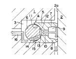
図1において、1はピストン、2はシリンダで、ピストン1の外周に形成されているリング溝3に組合せオイルリング4が装着されている。組合せオイルリング4は2ピースタイプのオイルリングで、金属製リング5と、その内周側に配置され金属製リング5をシリンダ2の内壁2aに押接する樹脂製リング6とから構成されている。
【0020】
金属製リング5は、合い口を有する略I字形断面のリングで、外周側に突出する上下2本のレール7,8間にオイル受容溝9を有し、その溝底に半径方向に貫通しているオイル戻し孔10を円周方向に複数個備えている。また、金属製リング5は、樹脂製リング6が配置される断面円弧形の内周溝11を内周側に有している。この金属製リング5の上下のレール7,8の外周面には窒化、クロムめっき、複合めっき、PVD皮膜等の所定の表面処理が施される。
【0021】
樹脂製リング6は、円形断面の外周に平坦部12を有している欠円形断面のリングである。したがって、樹脂製リング6の外周の平坦部12と、金属製リング5の内周溝11との間に隙間13が円周方向全体にわたって形成される。一方、樹脂製リング6の下面には内外周を貫通する溝14が円周方向に間隔をおいて複数個形成され、金属製リング5のオイル戻し孔10と通じるオイル通路15を形成している。溝14の底面は、外周側から内周側に向かって下傾している。
【0022】
この樹脂製リング6は、合い口を有し、合い口の突き当たった状態で熱膨張により張力が上昇する構造のリングである。すなわち、樹脂製リング6の張力は温度によって変化し、温度が高くなるに伴って張力が増加するようになっている。樹脂材料としては、例えばポリイミド樹脂が用いられる。
【0023】
したがって、樹脂製リング6によってシリンダ2の内壁2aに押し付けられた金属製リング5が、シリンダ2の内壁2aを摺動し、シリンダ2の内壁2aから掻き取ったオイルは、オイル受容溝9からオイル戻し孔10を通って金属製リング5の内周側の隙間13に入り、そこから樹脂製リング6の下面の溝14を通ってリング溝3内に流出し、リング溝3の底部に形成されているオイル戻し通路16からクランクケースに戻される。
【0024】
この際、エンジン始動時の低温時には、樹脂製リング6は低張力とされているため、金属製リング5とシリンダ2の内壁2aとの間は低摩擦となり、始動性が良好になる。また、通常運転時においても、樹脂製リング6は比較的低張力が得られ、低燃費化が可能となる。一方、高回転時には、樹脂製リング6の熱膨張によって、樹脂製リング6は高張力を発生するため、金属製リング6のシリンダ内壁2aへの追従性が良好で、高いシール性を確保することができる。
【0025】
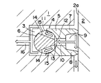
図2は、本発明の別の実施形態2を示している。本実施形態2は、上記実施形態1とは、樹脂製リング6に形成する溝の構成が相違しているだけで、他の構成は上記実施形態1と同じである。
【0026】
本実施形態2では、樹脂製リング6の上下面に半径方向に貫通する溝14を上下対称に形成したものである。樹脂製リング6の下面に形成されている溝14は、底面が上記実施形態1と同じく、外周側から内周側に向かって下傾している。これと対称的に、上面に形成された溝14は、底面が外周側から内周側に向かって上傾している。
【0027】
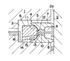
図3及び図4は、本発明の更に別の実施形態3を示している。本実施形態3は、上記第1の実施形態1とは、樹脂製リング6の断面形状が相違しているだけで、他の構成は同じである。
【0028】
本実施形態3では、樹脂製リング6は略正方形断面を備えており、外周側の上下の角部は金属製リング5の内周溝11に沿うよう円弧面に形成されている。そして、樹脂製リング6の下面には内外周を貫通する溝14が円周方向に間隔をおいて複数個形成されており、この溝14の底面も外周側から内周側に向かって下傾している。
【0033】
【発明の効果】
以上説明したように本発明によれば、オイルリングをエキスパンダで外側に押圧する組合せオイルリングにおいて、エキスパンダの張力をエンジンの始動時から高回転時にわたって適性な値とすることができ、エンジン始動時等における低摩擦化と高回転時の高いシール性とを得られる。
【図面の簡単な説明】
【図1】 本発明の一実施形態を示す縦断面図である。
【図2】 本発明の別の実施形態を示す縦断面図である。
【図3】 本発明の更に別の実施形態を示す縦断面図である。
【図4】 樹脂製リングの一部分を示す斜視図である。
【符号の説明】
1 ピストン
2 シリンダ
2a シリンダ内壁
3 リング溝
4 組合せオイルリング
5 金属製リング
6 樹脂製リング
7,8 レール
9 オイル受容溝
10 オイル戻し孔
11 内周溝
12 平坦部
13 隙間
14 溝
15 オイル通路
16 オイル戻し通路[0001]
BACKGROUND OF THE INVENTION
The present invention relates to a combined oil ring for a reciprocating engine comprising a metal ring and an expander ring, wherein the expander ring is a resin ring.
[0002]
[Prior art]
As an oil control ring for a reciprocating internal combustion engine, a plurality of oil return holes are formed at intervals in the circumferential direction at the bottom of an oil receiving groove formed between two upper and lower rails projecting outward. A two-piece type combined oil ring is used, which includes an oil ring and a coil expander that presses the oil ring radially outward (see, for example, Patent Document 1).
[0003]
On the other hand, a metal ring is placed on the outside, a resin ring is placed on the inside, and the joint of the resin ring hits due to thermal expansion above a predetermined temperature, generating tension that pushes the metal ring radially outward A combined piston ring for a pressure ring has been proposed (see Patent Document 2).
[0004]
[Patent Document 1]
Japanese Patent Publication No. 3-29979 [Patent Document 2]
Japanese Patent Laid-Open No. 2000-130583
[Problems to be solved by the invention]
Generally, when the engine speed increases, the followability of the ring to the bore deteriorates and the oil consumption deteriorates. In addition, the oil temperature is increased, the viscosity is decreased, and the oil consumption is further deteriorated due to the increase in evaporation components. However, with a combination oil ring that presses the oil ring radially outward with a coil expander, if the tension of the coil expander is increased, the friction between the oil ring and the cylinder increases at the time of engine start when the oil temperature is low. May occur. On the other hand, when the tension of the coil expander is reduced, the startability is good, but at the time of high rotation, the followability to the cylinder bore deformation of the oil ring is insufficient and the sealing performance may be deteriorated. As described above, the conventional type combined oil ring has a problem that it is difficult to make the tension an appropriate value from the start to the high rotation.
[0006]
On the other hand, a combination piston ring using a resin ring has a tendency that the tension changes depending on the temperature and the tension increases as the temperature increases. However, the combination piston ring described in Japanese Patent Laid-Open No. 2000-130583 is a pressure ring, and no oil ring is described.
[0007]
The present invention has been made in view of the above points, and the problem is that, in a combined oil ring that presses the oil ring outward with an expander, the tension of the expander is an appropriate value from the start of the engine to the high rotation. It is to provide a combination oil ring that makes it possible.
[0008]
[Means for Solving the Problems]
The present invention adopts the following means in order to solve the above problems. That is,
The present invention relates to a metal ring having an oil return hole at the bottom of an oil receiving groove formed between two upper and lower rails protruding to the outer peripheral side, and a groove formed on the inner peripheral side, and the metal In the combined oil ring consisting of an expander ring that is mounted on the inner circumferential groove of the ring and presses the metal ring radially outward,
The expander ring is a resin ring having a structure in which tension is increased by thermal expansion in a state where the abutment is in contact, and an oil passage communicating with an oil return hole of the metal ring is one of the upper and lower surfaces of the resin ring. Or it is formed with the groove | channel which penetrates the inner and outer periphery provided in both .
[0009]
According to the above configuration, the expander ring is a resin ring, and the tension varies depending on the temperature, and the tension increases as the temperature increases. Therefore, by setting the tension of the resin ring to a low tension at a low temperature when starting the engine, the friction between the metal ring and the cylinder becomes low, and the startability can be improved. Further, even during normal operation, a relatively low tension can be obtained, and fuel consumption can be reduced. On the other hand, at the time of high rotation, the resin ring can obtain a high tension due to the thermal expansion of the resin, the followability to the cylinder bore deformation of the metal ring is good, and high sealing performance can be secured.
[0010]
The oil scraped off by the metal ring flows into the ring groove through the oil receiving groove of the metal ring, the oil return hole, and the oil passage of the resin ring, and the oil return provided on the ring groove bottom and the ring groove lower surface. It is returned to the crankcase through the passage.
[0011]
By making the ring that slides with the cylinder a metal ring, the service life can be extended. In addition, since the rigidity is high, the width can be reduced. Abrasion resistance can be improved by subjecting the outer peripheral surface to a surface treatment such as nitriding, chromium plating, composite plating, or PVD coating.
[0013]
As compared with the case of forming the one in the groove of the upper bottom surface, towards the case of form form grooves in the upper and lower surfaces, good vertical balance of the resin ring, the followability to the movement of the metal ring The oil scraping performance can be improved without obstruction. In addition, since the amount of expansion of the resin is uniform and the force pushing the metal ring can be smoothed, the posture of the metal ring is stabilized and oil scraping is reliably performed.
[0016]
It is preferable that a gap is formed between the outer periphery of the resin ring and the inner peripheral groove of the metal ring. In this case, if the resin ring has a flat portion on the outer periphery, the gap is easily formed.
[0017]
The oil that flows into the inner circumference through the oil return hole of the metal ring flows in the circumferential direction through the gap formed by the outer circumference of the resin ring and the inner circumference groove of the metal ring, forming a resin ring. through grooves or Ranaru oil passage being so flows into the ring groove can be oil scraped by the metal ring flows smoothly into the ring groove.
[0018]
DETAILED DESCRIPTION OF THE INVENTION
Hereinafter, an embodiment of the present invention will be described with reference to the drawings.
[0019]
In FIG. 1, 1 is a piston, 2 is a cylinder, and a
[0020]
The
[0021]
The
[0022]
The
[0023]
Accordingly, the
[0024]
At this time, since the
[0025]
FIG. 2 shows another
[0026]
In the second embodiment, the
[0027]
3 and 4 show still another
[0028]
In the third embodiment, the
[0033]
【The invention's effect】
As described above, according to the present invention, in the combined oil ring that presses the oil ring outward with the expander, the tension of the expander can be set to a suitable value from the start of the engine to the high rotation time. Low friction at start-up and high sealing performance at high rotation can be obtained.
[Brief description of the drawings]
FIG. 1 is a longitudinal sectional view showing an embodiment of the present invention.
FIG. 2 is a longitudinal sectional view showing another embodiment of the present invention.
FIG. 3 is a longitudinal sectional view showing still another embodiment of the present invention.
FIG. 4 is a perspective view showing a part of a resin ring.
[Explanation of symbols]
DESCRIPTION OF SYMBOLS 1
Claims (3)
前記エキスパンダリングが、合い口の突き当たった状態で熱膨張により張力が上昇する構造の樹脂製リングであり、前記金属製リングのオイル戻し孔と通じるオイル通路がこの樹脂製リングの上下面の一方又は両方に設けられた内外周を貫通する溝で形成されていることを特徴とする組合せオイルリング。A metal ring having an oil return hole in the groove bottom of the oil receiving groove formed between the upper and lower two rails projecting to the outer peripheral side, and a groove formed on the inner peripheral side; In the combined oil ring consisting of an expander ring mounted on the inner circumferential groove and pressing the metal ring radially outward,
The expander ring is a resin ring having a structure in which tension is increased by thermal expansion in a state where the abutment is in contact, and an oil passage communicating with an oil return hole of the metal ring is one of the upper and lower surfaces of the resin ring. Or it is formed with the groove | channel which penetrates the inner and outer periphery provided in both, The combination oil ring characterized by the above-mentioned.
Priority Applications (1)
| Application Number | Priority Date | Filing Date | Title |
|---|---|---|---|
| JP2002280210A JP4040407B2 (en) | 2002-09-26 | 2002-09-26 | Combination oil ring |
Applications Claiming Priority (1)
| Application Number | Priority Date | Filing Date | Title |
|---|---|---|---|
| JP2002280210A JP4040407B2 (en) | 2002-09-26 | 2002-09-26 | Combination oil ring |
Publications (2)
| Publication Number | Publication Date |
|---|---|
| JP2004116635A JP2004116635A (en) | 2004-04-15 |
| JP4040407B2 true JP4040407B2 (en) | 2008-01-30 |
Family
ID=32274963
Family Applications (1)
| Application Number | Title | Priority Date | Filing Date |
|---|---|---|---|
| JP2002280210A Expired - Fee Related JP4040407B2 (en) | 2002-09-26 | 2002-09-26 | Combination oil ring |
Country Status (1)
| Country | Link |
|---|---|
| JP (1) | JP4040407B2 (en) |
Families Citing this family (1)
| Publication number | Priority date | Publication date | Assignee | Title |
|---|---|---|---|---|
| JP4724080B2 (en) * | 2006-09-14 | 2011-07-13 | トヨタ自動車株式会社 | Combination oil ring |
-
2002
- 2002-09-26 JP JP2002280210A patent/JP4040407B2/en not_active Expired - Fee Related
Also Published As
| Publication number | Publication date |
|---|---|
| JP2004116635A (en) | 2004-04-15 |
Similar Documents
| Publication | Publication Date | Title |
|---|---|---|
| EP1431630B1 (en) | Combined oil ring | |
| KR100566234B1 (en) | Side rail and combination oil control ring | |
| JP2010530045A (en) | Oil scraping ring | |
| KR20090035413A (en) | Piston ring of reciprocating engine | |
| JPH09144881A (en) | Combination oil ring | |
| JPH0329979B2 (en) | ||
| EP2017506A2 (en) | Combination of a piston and a piston ring | |
| JP4749399B2 (en) | Piston of internal combustion engine | |
| JP4382229B2 (en) | Combination oil ring | |
| JP4040407B2 (en) | Combination oil ring | |
| US10197160B2 (en) | Oil ring | |
| JP2005273583A (en) | piston ring | |
| JP4236910B2 (en) | Combination oil ring | |
| JP4900222B2 (en) | Piston of internal combustion engine | |
| JP7045383B2 (en) | piston ring | |
| US12037960B2 (en) | Piston and method for producing same | |
| JP4008327B2 (en) | Combination piston ring | |
| JP4008326B2 (en) | Combination piston ring | |
| JP4184041B2 (en) | Combination piston ring | |
| JP4323773B2 (en) | Piston device | |
| EP4502357A1 (en) | Piston unit, top land member, and combination of piston unit parts | |
| JPH08303590A (en) | Seal structure | |
| JP2004197820A (en) | Combination oil ring | |
| JP2008240718A (en) | Piston structure of two cycle internal combustion engine | |
| JPH08303298A (en) | Combination ring and seal structure equipped with it |
Legal Events
| Date | Code | Title | Description |
|---|---|---|---|
| A621 | Written request for application examination |
Free format text: JAPANESE INTERMEDIATE CODE: A621 Effective date: 20050616 |
|
| A977 | Report on retrieval |
Free format text: JAPANESE INTERMEDIATE CODE: A971007 Effective date: 20070427 |
|
| A131 | Notification of reasons for refusal |
Free format text: JAPANESE INTERMEDIATE CODE: A131 Effective date: 20070508 |
|
| A521 | Written amendment |
Free format text: JAPANESE INTERMEDIATE CODE: A523 Effective date: 20070702 |
|
| TRDD | Decision of grant or rejection written | ||
| A01 | Written decision to grant a patent or to grant a registration (utility model) |
Free format text: JAPANESE INTERMEDIATE CODE: A01 Effective date: 20071106 |
|
| A61 | First payment of annual fees (during grant procedure) |
Free format text: JAPANESE INTERMEDIATE CODE: A61 Effective date: 20071107 |
|
| FPAY | Renewal fee payment (prs date is renewal date of database) |
Free format text: PAYMENT UNTIL: 20101116 Year of fee payment: 3 |
|
| R150 | Certificate of patent (=grant) or registration of utility model |
Free format text: JAPANESE INTERMEDIATE CODE: R150 |
|
| FPAY | Renewal fee payment (prs date is renewal date of database) |
Free format text: PAYMENT UNTIL: 20101116 Year of fee payment: 3 |
|
| FPAY | Renewal fee payment (prs date is renewal date of database) |
Free format text: PAYMENT UNTIL: 20111116 Year of fee payment: 4 |
|
| S533 | Written request for registration of change of name |
Free format text: JAPANESE INTERMEDIATE CODE: R313533 |
|
| R350 | Written notification of registration of transfer |
Free format text: JAPANESE INTERMEDIATE CODE: R350 |
|
| FPAY | Renewal fee payment (prs date is renewal date of database) |
Free format text: PAYMENT UNTIL: 20121116 Year of fee payment: 5 |
|
| S531 | Written request for registration of change of domicile |
Free format text: JAPANESE INTERMEDIATE CODE: R313531 |
|
| FPAY | Renewal fee payment (prs date is renewal date of database) |
Free format text: PAYMENT UNTIL: 20121116 Year of fee payment: 5 |
|
| R350 | Written notification of registration of transfer |
Free format text: JAPANESE INTERMEDIATE CODE: R350 |
|
| FPAY | Renewal fee payment (prs date is renewal date of database) |
Free format text: PAYMENT UNTIL: 20121116 Year of fee payment: 5 |
|
| FPAY | Renewal fee payment (prs date is renewal date of database) |
Free format text: PAYMENT UNTIL: 20131116 Year of fee payment: 6 |
|
| LAPS | Cancellation because of no payment of annual fees |