JP4040142B2 - Flashing indicator - Google Patents
Flashing indicator Download PDFInfo
- Publication number
- JP4040142B2 JP4040142B2 JP18934397A JP18934397A JP4040142B2 JP 4040142 B2 JP4040142 B2 JP 4040142B2 JP 18934397 A JP18934397 A JP 18934397A JP 18934397 A JP18934397 A JP 18934397A JP 4040142 B2 JP4040142 B2 JP 4040142B2
- Authority
- JP
- Japan
- Prior art keywords
- solenoid
- coil
- lid
- current
- flashing indicator
- Prior art date
- Legal status (The legal status is an assumption and is not a legal conclusion. Google has not performed a legal analysis and makes no representation as to the accuracy of the status listed.)
- Expired - Lifetime
Links
Images


Landscapes
- Measurement Of Current Or Voltage (AREA)
- Electromagnets (AREA)
Description
【0001】
【発明の属する技術分野】
本発明は、送電線を支持する支持物に落雷があったことを表示する閃絡表示器に関するものである。
【0002】
【従来の技術】
電力の送配電線路への落雷事故を防止するため、電力線の上部に架空地線が張られている。この架空地線による遮蔽が効かず、電力線に落雷したときには、電力線の電位が大幅に上昇して碍子の絶縁能力を越え、送電線支持物である鉄塔にを経て大地に閃絡電流が流れ込む。また鉄塔に直接落雷したときには、鉄塔の電位が大幅に上昇し、碍子の絶縁能力を越えいわゆる逆閃絡電流が発生することもある。これらの閃絡事故により一旦放電路が形成されると、以後、送電中の電流がその放電路にそって大地に流れ込み、安全な送電状態を維持できなくなることがある。そのため、閃絡事故のあった鉄塔を速やかに発見し、補修対策を取らなければならない。
【0003】
落雷のあった鉄塔を発見する装置として、閃絡表示器が知られている。例えば実用新案登録第2529349号公報には、雷撃電流を検出してフラッシュランプを発光させ、その機械的強度の低下を利用し、バネの力によって蓋を開き表示布を表示する閃絡表示器が開示されている。実開平4−79268号公報には、雷撃電流を検出して内部回路が動作し、内蔵電源によりソレノイドを動作させて表示器の蓋を開け、表示布を表示する閃絡表示器が開示されている。
【0004】
【発明が解決しようとする課題】
上記した実用新案登録第2529349号の閃絡表示器は不可逆的な動作をするものであり、一度、表示器が表示動作をしてしまうと、以後使用できないため、その都度、新品の表示器に付け替えたり、部品の交換をしなければならなかった。一方、実開平4−79268号公報の閃絡表示器は可逆的な動作をするものであるが、動作の頻度や周囲温度、経年変化により内部電源の性能が劣化して動作の確実性が損なわれる危険があった。
【0005】
また従来の閃絡表示器は、雷撃電流の検知センサとなる変流器に空芯コイルを使用していた。空芯コイルは、出力電流が微少で安定しないため、閃絡表示器が誤動作することもあった。また空芯コイルで出力電流を変更するには、コイルの巻数を調節したり、出力側の抵抗を変えたり、あるいは閃絡表示器が取り付けられる鉄塔とコイルとの距離を微妙に調整するといった面倒な操作が必要になる。
【0006】
本発明はこれらの諸問題を解消するためになされたものである。内部電源を必要とせず、表示作動後に簡単な操作で容易にリセットして繰り返し使用でき、また検知センサであるコイルに安定した出力電流が得られるようにするとともに、出力電流を簡単な操作で変更できるようにし、保守やメンテナンスが容易な閃絡表示器を提供することを目的とする。
【0007】
【課題を解決するための手段】
前記の目的を達成するためになされた本発明を適用する閃絡表示器を実施例に対応する図面により説明すると以下のとおりである。
【0008】
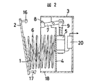
本発明の閃絡表示器は、図1、図2に示すとおり、表示媒体1を収納してある蓋2付き容器3と、蓋2および容器3のいずれか一方の側に固設され、もう一方の側に掛合したソレノイド5と、雷撃電流を検出する検出コイル11とを有し、検出コイル11の出力がソレノイド5の駆動源として連結され、ソレノイド5の駆動により前記掛合が解除されて蓋2が開くことにより表示媒体1が露出(図3参照)するように構成されている。図4に示すとおり、検出コイル11の巻き芯12の中空に、磁性材13を挿脱可能にする。
【0009】
同じく図1に示すとおり、蓋2と容器3との間がコイルバネ6により連結され、コイルバネ6の中心部の空間に表示媒体1である布を屏風たたみにして収納することで適切に実施できる。
【0010】
検出コイル11の巻き芯12の中空に、磁性材13を挿脱可能にすることで、検出コイル11の出力電流を調整することができる。
検出コイル11の出力がソレノイド5の駆動源として連結される回路20として、図5に示すとおり、検出コイル11の出力電流を整流する整流回路21、および整流回路21の出力電流を充電しておくコンデンサ22を有し、その放電電流でソレノイド5が動作するように構成されている。この回路20が存在することにより、ソレノイド5は雷撃電流を由来とする電流エネルギーで駆動されることになり、閃絡表示器自体は格別な動作電源を持たなくても済む。
【0011】
【発明の実施の形態】
以下、本発明の実施例を図面により詳細に説明する。図1は本発明を適用する閃絡表示器の動作待機状態の要部を示す断面図、図2は同じく動作途中の状態を示す断面図、図3は動作後の状態を示す全体斜視図である。
【0012】
閃絡表示器の全体は、蓋2が嵌められた容器3の中にソレノイド5、コイルバネ6、表示布1、回路20が収納され、コイルケース10に収納された検出コイル11が回路20を介してソレノイド5に連結している。容器3はコイルケース10に取り付けられ、コイルケース10が雷撃電流を検出すべき送電線鉄塔30の適当な箇所に密接して取り付けられる。
【0013】
ソレノイド5は常時吸引のラッチング型であり、容器3と一体的なシャーシ4に取り付けられている。そのプランジャ9に連結した回動レバー7はシャーシ4に軸支され、回動レバー7の先端鉤8が蓋2に取り付けられた掛止鉤16と離脱可能に掛合している。また蓋2に取り付けられた掛止鉤17は容器3に取り付けられた掛止孔18に緩嵌している。
【0014】
一方、シャーシ4と蓋2にはコイルバネ6が連結し、圧縮状態で挟み込まれている。さらにコイルバネ6の中心部の空間には、コイルバネ6が伸張したときの長さと略同等程度の長さを持つ表示用の巾布1がシャーシ4および蓋2に両端を連結して屏風たたみで納められている。
【0015】
検出コイル11は、図4に示すとおり、矩形のボビン(巻き芯)12に巻いてあるものである。ボビン12の中空には板状の磁性材13を複数枚挿入してあり、これらは抜きとることもでき、磁性材13を任意の枚数挿入して検出コイル11の出力電流を調整できるようになっている。検出コイル11はコイルケース10に収納され、ケース10の側面に窺たれた孔からリード線が導出され回路20に連結されている。ケース10の両端は端板14で覆われている。
【0016】
図5に示す回路20は、入力が検出コイル11の出力に連結しており、バリスタ23、整流回路21、コンデンサ24、リレー25、コンデンサ22を有し、出力がソレノイド5に連結されている。バリスタ23は検出コイル11の出力電圧からサージ電圧を吸収し、安定な電圧を得るものである。整流回路21はダイオードがブリッジに組まれて全波整流をする。コンデンサ24は整流回路21の出力電流を蓄えるものである。コンデンサ22は同じく整流回路21の出力電流を蓄えるものであるが容量がコンデンサ24よりも大きい。
【0017】
この閃絡表示器は、図3に示すとおり、送電線鉄塔30に取り付けられ、落雷等により鉄塔30に雷撃電流が流れると周囲に磁界が発生し、その磁界を検出コイル11が検出して電流が出力される。
【0018】
この出力電流は、回路20に流れ込み、整流回路21で整流され、コンデンサ24、コンデンサ22に蓄えられてからリレー25のコイルに電流が流れる。そのためリレー25がオンになるので、ソレノイド5に出力電流が流れる。このとき雷撃電流が既に途絶えていてもコンデンサ22に蓄積された電気量によりソレノイド5が動作するに充分な電流が流れる。
【0019】
ソレノイド5に電流が流れると、図1に示す状態から、ソレノイド5のプランジャ9が押され、回動レバー7が反時計方向に回動するので、先端鉤8が掛止鉤16との掛合から離れ、蓋2の掛止が解放される。ここで圧縮状態のバネ6の反発力により蓋2が押され、掛止鉤17が掛止孔18から抜ける(図2参照)。蓋2はバネ6が伸張しきるまで落ちてぶら下がり、表示布1の屏風たたみはのびて拡がり、コイルバネ6の線条の間を通して遠方からでも表示布1を視認できるようになる(図3参照)。
【0020】
この表示状態にある閃絡表示器を以下の手順でリセットする。回路20のコンデンサ22は既に放電しているので、ソレノイド5は回動レバー7を時計方向に人手にて戻すことにより、動作前のプランジャ9が吸引状態になる。そしてぶら下がっている蓋2を人手にて持ち、掛止鉤17を掛止孔18に合わせて容器3に蓋2を填め込むと、掛止鉤16が先端鉤8を押し、回動レバー7が若干回動してから戻り、掛止鉤16と先端鉤8とが掛り合い、さらに掛止鉤17が掛止孔18に緩嵌して蓋2が容器3に安定して填る。このときコイルバネ6は圧縮されてゆき、同時に表示布1は折り癖により、屏風たたみされて収納される。すなわち閃絡表示器は図1に示す初期状態に復帰する。
【0021】
上記のように、この閃絡表示器は、表示布1の復帰動作がコイルバネ6を戻す作業、すなわち蓋2を容器3に填める作業と連動しているため、表示布1を巻き上げる等の格別な作業が不要となり、きわめて簡単にリセットを完了することができる。
【0022】
さらに、この閃絡表示器は、検出コイル11のボビン12の中空には磁性材13を挿入してあるため、鉄塔30を流れる雷撃電流に対する検出コイルの感度が上がり、検出コイル11からソレノイド5を動作させるために充分な電流を得られ、ソレノイド5を動作させるための格別な電源を必要としない。
【0023】
また、ボビン12の中空に挿入する磁性材13の挿入数を自在に調整できるので、検出コイル11の出力電流を容易に変えることができる。なお、ボビン12の形状は図示の矩形のみならず円形でもよいし、中空に挿入する磁性材13は板状のみならず棒状の複数本または単数本でもよい。磁性材13の挿入数を調整するだけではなく、磁性材13の挿入深さを調整して検出コイル11の出力電流を変えることもできる。
【0024】
磁性材13の挿入数が検出コイル11の出力電流に与える影響を調べるため、図6に示す試験回路の装置を作成して測定を行った。この試験回路は、高電圧電源31、手動スイッチ32、コンデンサ33および34、ソレノイドスイッチ35、波形調整用コイル36、抵抗37を有している。この試験回路で、手動スイッチ32を入れると高電圧電源31からコンデンサ33および34が充電される。次いで手動スイッチ32を切り、ソレノイドスイッチ35を入れてコンデンサ33および34を放電すると、鉄塔の材質と同等のアングル材30Aに模擬的な雷撃電流が流れる。この模擬雷撃電流はシャント抵抗38により電圧変換されて図示外のオシロスコープにて観察することができる。アングル材30Aには、図4に示すコイルケース10に収納された検出コイル11が取り付けられており、模擬雷撃電流を検知して出力電流が得られる。検出コイル11には、図5に示す回路20が接続されている。図5では回路20の出力はソレノイド5に接続されているが、ここでは出力エネルギの測定のためであるから、ソレノイド5の替わりに図示外のオシロスコープに接続しておく。したがって検出コイル11から回路20を通った後の出力電気エネルギーがオシロスコープで観測できる。
【0025】
この試験回路の装置により、検出コイル11のボビン12の中空に挿入する磁性材13の枚数を種々に変え、検出コイル11から回路20を通った後の出力電気エネルギーをオシロスコープで測定した結果を図7に示す。磁性材13としてはパーマロイ系の磁性材を使用した。模擬雷撃電流は800Aのインパルス電流、インパルス波頭長/波尾長時間は8/20μsで、オシロスコープにて観察された。アングル材30AのサイズはL65×65である。また検出コイル11については巻数が4巻、6巻、10巻、12巻のもについて、各々測定した。
【0026】
【発明の効果】
以上、詳細に説明したように本発明を適用する閃絡表示器は、表示作動後に簡単な操作で容易に初期状態に復帰して繰り返し使用できる。雷撃電流のセンサである検出コイルに安定した高出力電流が得られるため閃絡表示器自身を作動させるための格別な電源を必要としない。また検出コイルの出力電流を簡単な操作で変更できるようになる。したがって、閃絡表示器の調整、保守やメンテナンスが非常に容易なものとなる。
【図面の簡単な説明】
【図1】本発明を適用する閃絡表示器の動作待機状態の要部を示す断面図である。
【図2】本発明を適用する閃絡表示器の動作途中の状態を示す断面図である。
【図3】本発明を適用する閃絡表示器の動作後の状態を示す全体斜視図である。
【図4】本発明を適用する閃絡表示器に使用される検出コイルの詳細な斜視図である。
【図5】本発明を適用する閃絡表示器の回路図である。
【図6】本発明を適用する閃絡表示器の性能評価をする装置の回路図である。
【図7】本発明を適用する閃絡表示器の性能評価の結果を示す図である。
【符号の説明】
1は表示布、2は蓋、3は容器、4はシャーシ、5はソレノイド、6はコイルバネ、7は回動レバー、8は先端鉤、9はプランジャ、10はコイルケース、11は検出コイル、12はボビン、13は磁性材、14は端板、16は掛止鉤、17は掛止鉤、18は掛止孔、19は、20は回路、21は整流回路、22はコンデンサ、23はバリスタ、24はコンデンサ、25はリレー、30は送電線鉄塔、31は高電圧電源、32は手動スイッチ、33はコンデンサ、34はコンデンサ、35はソレノイドスイッチ、36は波形調整用コイル、37は抵抗、38はシャント抵抗、30Aはアングル材。[0001]
BACKGROUND OF THE INVENTION
The present invention relates to a flashing indicator that indicates that a lightning strike has occurred on a support that supports a power transmission line.
[0002]
[Prior art]
In order to prevent lightning strikes on the power transmission and distribution line, an overhead ground line is installed above the power line. When the overhead ground wire is not shielded and lightning strikes the power line, the potential of the power line rises significantly and exceeds the insulation capacity of the insulator, and a flash current flows into the ground through the steel tower that supports the transmission line. In addition, when a lightning strikes directly on the tower, the potential of the tower rises significantly, and the so-called reverse flash current may occur, exceeding the insulation capacity of the insulator. Once a discharge path is formed due to these flashing accidents, a current during power transmission may flow into the ground along the discharge path, and a safe power transmission state may not be maintained. For this reason, it is necessary to promptly find the tower where the flash accident occurred and take repair measures.
[0003]
A flashing indicator is known as a device for detecting a lightning-powered tower. For example, Japanese Utility Model Registration No. 2529349 discloses a flashing indicator that detects a lightning strike current, causes a flash lamp to emit light, uses a decrease in mechanical strength, and opens a lid by a spring force to display a display cloth. It is disclosed. Japanese Utility Model Publication No. 4-79268 discloses a flashing indicator that detects a lightning strike current, operates an internal circuit, operates a solenoid by a built-in power supply to open a lid of the display, and displays a display cloth. Yes.
[0004]
[Problems to be solved by the invention]
The flashing indicator of the utility model registration No. 2529349 described above operates irreversibly, and once the display unit performs display operation, it cannot be used thereafter. I had to change or replace parts. On the other hand, the flashing indicator disclosed in Japanese Utility Model Publication No. 4-79268 is reversible, but the performance of the internal power supply deteriorates due to the frequency of operation, ambient temperature, and aging, and the certainty of the operation is lost. There was a risk of being caught.
[0005]
In addition, the conventional flashing indicator uses an air-core coil as a current transformer serving as a lightning current detection sensor. Since the air-core coil has a small output current and is not stable, the flashing indicator sometimes malfunctions. Also, changing the output current with an air-core coil requires the trouble of adjusting the number of turns of the coil, changing the resistance on the output side, or finely adjusting the distance between the tower to which the flashing indicator is attached and the coil. Operation is required.
[0006]
The present invention has been made to solve these various problems. It does not require an internal power supply, can be easily reset and used repeatedly after a display operation, and a stable output current can be obtained in the coil that is the detection sensor, and the output current can be changed with a simple operation. You can make it in, and it is an object of maintenance and maintenance to provide easy blende fault indicator.
[0007]
[Means for Solving the Problems]
A flashing indicator to which the present invention is applied to achieve the above object will be described below with reference to the drawings corresponding to the embodiments.
[0008]
As shown in FIGS. 1 and 2, the flashing indicator of the present invention is fixed to a
[0009]
Similarly, as shown in FIG. 1, the
[0010]
Hollow of the
As a
[0011]
DETAILED DESCRIPTION OF THE INVENTION
Hereinafter, embodiments of the present invention will be described in detail with reference to the drawings. FIG. 1 is a cross-sectional view showing a main part of an operation standby state of a flashlight display to which the present invention is applied, FIG. 2 is a cross-sectional view showing a state during operation, and FIG. 3 is an overall perspective view showing a state after operation. is there.
[0012]
The whole flashing indicator has a
[0013]
The
[0014]
On the other hand, a
[0015]
The
[0016]
The
[0017]
As shown in FIG. 3, this flashing indicator is attached to the
[0018]
This output current flows into the
[0019]
When a current flows through the
[0020]
The flashing indicator in this display state is reset by the following procedure. Since the
[0021]
As described above, this flashing indicator is operated in a manner that the returning operation of the
[0022]
Further, in this flashing indicator, since the
[0023]
Further, since the number of
[0024]
In order to investigate the influence of the number of inserted
[0025]
The results of measuring the output electrical energy after passing through the
[0026]
【The invention's effect】
As described above in detail, the flashing indicator to which the present invention is applied can be easily used after being returned to the initial state by a simple operation after the display operation. Since a stable high output current is obtained in the detection coil which is a lightning current sensor, no special power source for operating the flashing indicator itself is required. In addition, the output current of the detection coil can be changed with a simple operation. Therefore, adjustment, maintenance, and maintenance of the flashing indicator become very easy.
[Brief description of the drawings]
FIG. 1 is a cross-sectional view showing a main part of an operation standby state of a flashing indicator to which the present invention is applied.
FIG. 2 is a cross-sectional view showing a state during operation of a flashing indicator to which the present invention is applied.
FIG. 3 is an overall perspective view showing a state after the operation of the flashing indicator to which the present invention is applied.
FIG. 4 is a detailed perspective view of a detection coil used in a flashing indicator to which the present invention is applied.
FIG. 5 is a circuit diagram of a flashing indicator to which the present invention is applied.
FIG. 6 is a circuit diagram of an apparatus for evaluating the performance of a flashing indicator to which the present invention is applied.
FIG. 7 is a diagram showing the results of performance evaluation of a flashing indicator to which the present invention is applied.
[Explanation of symbols]
1 is a display cloth, 2 is a lid, 3 is a container, 4 is a chassis, 5 is a solenoid, 6 is a coil spring, 7 is a rotating lever, 8 is a tip rod, 9 is a plunger, 10 is a coil case, 11 is a detection coil, 12 is a bobbin, 13 is a magnetic material, 14 is an end plate, 16 is a latching rod, 17 is a latching rod, 18 is a latching hole, 19 is a circuit, 21 is a rectifier circuit, 22 is a capacitor, and 23 is Varistor, 24 is a capacitor, 25 is a relay, 30 is a transmission line tower, 31 is a high voltage power source, 32 is a manual switch, 33 is a capacitor, 34 is a capacitor, 35 is a solenoid switch, 36 is a coil for adjusting a waveform, 37 is a resistor , 38 is a shunt resistor, and 30A is an angle material.
Claims (3)
Priority Applications (1)
| Application Number | Priority Date | Filing Date | Title |
|---|---|---|---|
| JP18934397A JP4040142B2 (en) | 1997-07-15 | 1997-07-15 | Flashing indicator |
Applications Claiming Priority (1)
| Application Number | Priority Date | Filing Date | Title |
|---|---|---|---|
| JP18934397A JP4040142B2 (en) | 1997-07-15 | 1997-07-15 | Flashing indicator |
Publications (2)
| Publication Number | Publication Date |
|---|---|
| JPH1140315A JPH1140315A (en) | 1999-02-12 |
| JP4040142B2 true JP4040142B2 (en) | 2008-01-30 |
Family
ID=16239753
Family Applications (1)
| Application Number | Title | Priority Date | Filing Date |
|---|---|---|---|
| JP18934397A Expired - Lifetime JP4040142B2 (en) | 1997-07-15 | 1997-07-15 | Flashing indicator |
Country Status (1)
| Country | Link |
|---|---|
| JP (1) | JP4040142B2 (en) |
Families Citing this family (1)
| Publication number | Priority date | Publication date | Assignee | Title |
|---|---|---|---|---|
| EP2278670B1 (en) * | 2009-07-23 | 2012-03-21 | Société Anonyme des Ets. CATU | Signalisation device of the short-circuit state of an overvoltage protection arrester of one phase of an electric transport net |
-
1997
- 1997-07-15 JP JP18934397A patent/JP4040142B2/en not_active Expired - Lifetime
Also Published As
| Publication number | Publication date |
|---|---|
| JPH1140315A (en) | 1999-02-12 |
Similar Documents
| Publication | Publication Date | Title |
|---|---|---|
| US7576960B2 (en) | Circuit protection device with automatic monitoring of operation fault | |
| US8154832B2 (en) | Leak detection and leak protection circuit | |
| US9118174B2 (en) | GFCI with voltage level comparison and indirect sampling | |
| WO2015109041A2 (en) | Self-test gfci device with dual solenoid coil electronic control | |
| CA2978772A1 (en) | Apparatus for mounting an overhead monitoring device | |
| CN101227076A (en) | Fault self-checking circuit of earthing fault breaker | |
| US20160181047A1 (en) | Ground fault circuit interrupter (gfci) system and method | |
| CN110632450B (en) | Intelligent low-voltage distribution network patrol instrument device | |
| JP4040142B2 (en) | Flashing indicator | |
| CN100501897C (en) | Flameproof protection switch | |
| CN103091600B (en) | Electric power circuit fault indicator | |
| CN214585908U (en) | Indicator light detector | |
| JP4127895B2 (en) | Surge current detection display device and sensitivity setting method thereof | |
| CN210605978U (en) | Load fire alarm circuit | |
| CN114937982A (en) | PT inrush current suppression method based on national net core terminal monitoring data source | |
| JP5499269B2 (en) | Surge counter | |
| CN113299494A (en) | Ground Fault Circuit Interrupter (GFCI) systems and methods | |
| CN200983344Y (en) | Fireproof protection switch | |
| CN212723154U (en) | Monitor structure for lightning arrester | |
| CN215910569U (en) | Power adapter aging testing box | |
| CN219758470U (en) | Safety detection device | |
| CN211044183U (en) | Computer power-off prevention device | |
| CN202975235U (en) | Mutual inductor polarity testing miniature operation box | |
| CN221039226U (en) | On-line monitoring circuit for voltage of opening and closing operation coil of circuit breaker | |
| CN210442495U (en) | Closed electrical equipment internal short circuit detection stick |
Legal Events
| Date | Code | Title | Description |
|---|---|---|---|
| A521 | Written amendment |
Free format text: JAPANESE INTERMEDIATE CODE: A523 Effective date: 20040713 |
|
| A621 | Written request for application examination |
Free format text: JAPANESE INTERMEDIATE CODE: A621 Effective date: 20040713 |
|
| A977 | Report on retrieval |
Free format text: JAPANESE INTERMEDIATE CODE: A971007 Effective date: 20070307 |
|
| A131 | Notification of reasons for refusal |
Free format text: JAPANESE INTERMEDIATE CODE: A131 Effective date: 20070403 |
|
| A521 | Written amendment |
Free format text: JAPANESE INTERMEDIATE CODE: A523 Effective date: 20070601 |
|
| TRDD | Decision of grant or rejection written | ||
| A01 | Written decision to grant a patent or to grant a registration (utility model) |
Free format text: JAPANESE INTERMEDIATE CODE: A01 Effective date: 20071023 |
|
| A61 | First payment of annual fees (during grant procedure) |
Free format text: JAPANESE INTERMEDIATE CODE: A61 Effective date: 20071107 |
|
| FPAY | Renewal fee payment (event date is renewal date of database) |
Free format text: PAYMENT UNTIL: 20101116 Year of fee payment: 3 |
|
| R150 | Certificate of patent or registration of utility model |
Free format text: JAPANESE INTERMEDIATE CODE: R150 |
|
| FPAY | Renewal fee payment (event date is renewal date of database) |
Free format text: PAYMENT UNTIL: 20101116 Year of fee payment: 3 |
|
| FPAY | Renewal fee payment (event date is renewal date of database) |
Free format text: PAYMENT UNTIL: 20101116 Year of fee payment: 3 |
|
| FPAY | Renewal fee payment (event date is renewal date of database) |
Free format text: PAYMENT UNTIL: 20111116 Year of fee payment: 4 |
|
| FPAY | Renewal fee payment (event date is renewal date of database) |
Free format text: PAYMENT UNTIL: 20111116 Year of fee payment: 4 |
|
| FPAY | Renewal fee payment (event date is renewal date of database) |
Free format text: PAYMENT UNTIL: 20121116 Year of fee payment: 5 |
|
| FPAY | Renewal fee payment (event date is renewal date of database) |
Free format text: PAYMENT UNTIL: 20121116 Year of fee payment: 5 |
|
| FPAY | Renewal fee payment (event date is renewal date of database) |
Free format text: PAYMENT UNTIL: 20121116 Year of fee payment: 5 |
|
| FPAY | Renewal fee payment (event date is renewal date of database) |
Free format text: PAYMENT UNTIL: 20121116 Year of fee payment: 5 |
|
| FPAY | Renewal fee payment (event date is renewal date of database) |
Free format text: PAYMENT UNTIL: 20131116 Year of fee payment: 6 |
|
| FPAY | Renewal fee payment (event date is renewal date of database) |
Free format text: PAYMENT UNTIL: 20131116 Year of fee payment: 6 |
|
| R250 | Receipt of annual fees |
Free format text: JAPANESE INTERMEDIATE CODE: R250 |
|
| R250 | Receipt of annual fees |
Free format text: JAPANESE INTERMEDIATE CODE: R250 |
|
| R250 | Receipt of annual fees |
Free format text: JAPANESE INTERMEDIATE CODE: R250 |
|
| EXPY | Cancellation because of completion of term |