JP4039745B2 - Image recording / playback device - Google Patents
Image recording / playback device Download PDFInfo
- Publication number
- JP4039745B2 JP4039745B2 JP20428798A JP20428798A JP4039745B2 JP 4039745 B2 JP4039745 B2 JP 4039745B2 JP 20428798 A JP20428798 A JP 20428798A JP 20428798 A JP20428798 A JP 20428798A JP 4039745 B2 JP4039745 B2 JP 4039745B2
- Authority
- JP
- Japan
- Prior art keywords
- mode
- recording
- image
- playback
- digital camera
- Prior art date
- Legal status (The legal status is an assumption and is not a legal conclusion. Google has not performed a legal analysis and makes no representation as to the accuracy of the status listed.)
- Expired - Lifetime
Links
Images


Description
【0001】
【発明の属する技術分野】
本発明は、撮像素子の出力に基づく画像データを、適用された記録媒体に記録し、或いは、該記録媒体に記録された画像を再生するようになされた、例えば画像再生機能付きのディジタルカメラ等の画像記録再生装置に関する。
【0002】
【従来の技術】
従来、例えばディジタルカメラ等の画像記録再生装置においては、撮像素子の出力に基づく画像データを適用された記録媒体に記録する記録モードとこの記録媒体に記録された画像データを読み出して表示器に可視像として再生するための再生モードとの何れのモードで動作させるかの選択切り換えを行なう場合、その都度、動作モードの選択切り換え操作を行ってモードを切り換えるのが普通であった。
【0003】
従って、ディジタルカメラで撮影を行なうに際して、既に再生モードに設定されているときには、単純にレリーズスイッチ(記録トリガスイッチ)を押すだけでは撮影動作が起動しないので先ず記録モードへの選択切り換え操作を行なう必要がある。このため、常にその時点でカメラに設定されている動作モードが記録モードであるのか再生モードであるのかを意識しておかなくてはならなず、操作が煩雑である。
【0004】
尚、記録モード、再生モード、および、消去モードの動作モードを有する電子スチルカメラに関する従来技術を記載した文献として、例えば次のようなものがある。
・実開昭63−99479号公報
【0005】
上記公報には、電子スチルカメラにおいて、撮影のためのトリガスイッチである記録スイッチを消去モードでの消去動作を起動させるためのスイッチとしても兼用させるようにすることで、スイッチの数を少なくして構成を簡素化することが提案されている。
【0006】
上記公報に開示された電子スチルカメラでは、モード選択手段によって消去モードが選択されているときに記録スイッチを操作すると、記録媒体に記録されている画像が消去されるように構成されている。
【0007】
上記公報の電子スチルカメラでは、既に再生モードに設定されている状態でこれから撮影しようとする場合には、先ず再生モードから記録モードへのモード切り換え操作を行なう必要があり、従って、撮影を意図したときにカメラに設定されている動作モードが記録モードであるのか再生モードであるのかを意識して操作しなくてはならなず、取り扱いが煩雑である。しかしながら、上記公報にはこのような視点からの課題や解決手段などについては一切開示されていない。
【0008】
【発明が解決しようとする課題】
本発明は叙上のような事情に鑑みてなされたものであり、動作モードが記録モードであるのか再生モードであるのかを意識せずに操作しても撮影を行なうことができるように構成された取り扱いが容易な新規なこの種の画像記録再生装置を提供することを目的とする。
【0009】
【課題を解決するための手段および作用】
上記課題を解決するために本願発明の画像記録再生装置は、所定の操作を繰り返す毎に、撮像素子の出力に基づく画像データを、適用された記録媒体に記録する記録モードと、当該記録媒体に記録された画像データを読み出して、適用された表示器に可視像として再生するための再生モードとに交互に切り換えるためのモード切り換えスイッチと、記録動作を行わせるためのレリーズスイッチと、再生モードが選択されているとき、前記レリーズスイッチが操作されたとき自動的に記録モードに切り換える制御手段と、を備えたことを特徴とするものである。
【0016】
【発明の実施の形態】
以下、図面を用いて本願発明の実施の形態について詳細に説明することにより本発明を明らかにする。
【0017】
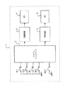
図1は、本発明の一つの実施の形態としての画像記録再生装置であるディジタルカメラの制御系統の構成を示す概念図である。
【0018】
図2は、図1のディジタルカメラを斜め上方から見た斜視図である。
【0019】
図3は、図1のディジタルカメラを背面側斜め下方から見た斜視図である。
【0020】
図1、図2及び図3に示されたディジタルカメラ1では、システムコントローラ2によって系全体が統括的に制御される。このシステムコントローラ2が記録回路3に指令を与え、該記録回路3を介して撮像素子としてのCCD4を駆動させて所定の撮像動作を行わしめるように構成されている。記録回路3はこの撮像動作により生成されたCCD4の出力に基づいて画像データを形成し、このディジタルカメラ1に適用されたメモリカード等の公知の記録媒体(不図示)に記録するように構成されている。また、システムコントローラ2が再生回路5に指令を与え、該再生回路5を介して表示素子としてのLCD6を駆動させて所定の画像表示動作を行わしめるように構成されている。
【0021】
図2の斜視図に示されるように、全体として撮像レンズ7が前方に向けて突出した形状のこのディジタルカメラ1のボディ上面側に、時計方向または反時計方向への回動操作によってテレ側またはワイド側へのズーム操作を行なうための、環状部材の一部に操作子が外側に突出した形状のズームレバー8が図示のように設けられ、環状のこのズームレバー8の内側に同心的に位置するようにしてレリーズボタン9が設けられている。
【0022】
また、このディジタルカメラ1では、ボディ上面側の図示の位置に、再生モードボタン10が設けられ、この再生モードボタン10の操作に応じてオンする再生モードスイッチ10-1による操作信号がシステムコントローラ2に入力されるように構成されている。再生モードボタン10が操作されることによってこの操作信号がシステムコントローラ2に入力されると、これに基づいてディジタルカメラ1は再生モードで動作するようになる。尚、この実施の形態では、再生モードボタン10に対する再度の操作により初回の操作で一旦再生モードでの動作状態になったディジタルカメラ1を記録モードでの動作に復帰させるための指令をシステムコントローラ2に入力するように機能する(実際にはシステムコントローラ側で入力指令をこのように認識する)構成になされている。
【0023】
図2のレリーズボタン9は公知の2段操作型のもので、その1段目の操作に応じてオンすることによりフォーカシング動作等を起動させるための1段目トリガスイッチ9-1と2段目の操作に応じてオンすることにより画像の記録を行なうための2段目トリガスイッチ9-2との各スイッチによる操作信号がシステムコントローラ2に入力されるように構成されている。
【0024】
また、このズームレバー8はその時計方向への回動操作によってオンするワイド側ズームスイッチ8-1と、その反時計方向への回動操作によってオンするテレ側ズームスイッチ8-2とを動作させ、ワイド側へのズーム操作を行なうための操作信号またはテレ側へのズーム操作を行なうための操作信号をシステムコントローラ2に入力するように構成されている。
【0025】
このディジタルカメラ1は、CCD4の出力に基づく画像データをメモリカード等の適用された記録媒体に記録する記録モードとこの記録媒体に記録された画像データを読み出して表示器であるLCD6に可視像として再生するための再生モードとの何れかのモードを選択的にとって動作するようになされた画像記録再生装置であって、上述のシステムコントローラ2によって記録モードまたは再生モードが選択的に設定される。
【0026】
図3の斜視図に示されるように、このディジタルカメラ1の背面11側にLCD6による表示画面12が配され、また、この表示画面12で表示される再生画像を選択するための画像選択ボタン13,14が図示のように設けられている。この画像選択ボタン13,14は、例えば、一方側(13)に対する毎回の操作で画像のコマ番号が順次遡及する方向の、また、他方側(14)の操作で画像のコマ番号が順次進む方向の選択操作を行なうためのものである。
【0027】
図4は図1〜図3を用いて説明したディジタルカメラの動作を説明するためのフローチャートである。
【0028】
次に、この図4のフローチャートを用いて上述したディジタルカメラ1の動作について詳細に説明する。
電源を投入して起動させると(S101)、このディジタルカメラ1はシステムコントローラ2による制御により先ず撮像素子の出力に基づく画像データを適用された記録媒体(メモリカード)に記録する記録モードで動作する状態に設定される(S102)。
【0029】
電源を切断する指令の有無が監視され(S103)、この指令が有ると認識されれば動作を終了するが、この指令が認識されない間は、再生モードボタン10の操作に応動する再生モードスイッチ10-1からの操作信号が発生したか否かを監視しつつ(S104)、この操作信号の発生が認識されない限り記録モードでの動作を継続する。
【0030】
記録モードが設定されているときには、上述のズームレバー8によるズーム操作が有効に行われ、また、レリーズボタン9への1段目の操作に応動してフォーカシング動作が行われ、2段目の操作に応動して適用されたメモリカードに画像データを格納する記録動作が行なわれる。
【0031】
一方、上記記録モードが設定されているときに再生モードボタン10が操作されると(S104)、システムコントローラ2により再生モードの経過時間のカウントが開始され(S105)、ディジタルカメラ1は再生モードで動作する状態に設定される(S106)。
【0032】
記録モードが設定されているときには、このディジタルカメラ1に適用された記録媒体(メモリカード)に記録された画像データが読み出され表示器である上述の表示画面12に可視像として再生表示される。既述のように、画像選択ボタン13,14に対する毎回の操作で画像のコマ番号が順次遡及し、または、順次進むように再生画像の選択操作が行なわれ得る。
【0033】
電源を切断する指令の有無が監視され(S107)、この指令が発されたと認識されれば、これで動作を終了するが、この指令が発されない限り上記ステップ(S105)で開始した再生モードの経過時間のカウント値が所定値を越えたか否かの判断動作に移行する(S108)。
【0034】
上記ステップ(S108)で、再生モードでの経過時間(カウント値)が所定値を越えと判断されたときには上記(S102)の記録モードで動作する状態に自動的に復帰する。これ以降は既述の各ステップ(S103)〜(S107)までと同様となる。
【0035】
一方、上記ステップ(S108)で、再生モードでの経過時間(カウント値)が所定値を越えていないと判断されたときには、再生モードボタンを押したか否か(ステップS104で一度押されているので、このステップでは再度押されたか否か)が判断される(S109)。既述のとおり、再生モードボタンを再度押すとシステムコントローラ2は記録モードを設定する指令が入力されたものと認識する。
【0036】
上記ステップ(S109)で再生モードボタンを押したと判断されたときにも上記(S102)の記録モードで動作する状態に自動的に復帰する。これ以降は既述の各ステップ(S103)〜(S108)までと同様となる。
【0037】
一方、上記ステップ(S109)で、再生モードボタンが押されていないと判断されたときには、次のステップ(S110)でズームレバーを操作したか否かが判断される。
【0038】
上記ステップ(S110)でズームレバーを操作したと判断されたときにも上記(S102)の記録モードで動作する状態に自動的に復帰する。これ以降は既述の各ステップ(S103)〜(S109)までと同様となる。
【0039】
一方、上記ステップ(S110)で、ズームレバーが操作されていないと判断されたときには、レリーズボタンを押したか否かが判断される(S111)。
【0040】
上記ステップ(S111)でレリーズボタンを押したと判断されたときにも上記(S102)の記録モードで動作する状態に自動的に復帰する。これ以降は既述の各ステップ(S103)〜(S110)までと同様となる。
【0041】
上記ステップ(S111)で、レリーズボタンを押していないと判断されたときには、ステップ(S106)で設定されたとおりのディジタルカメラ1を再生モードで動作させる状態を維持する。
【0042】
つまり、本実施の形態のディジタルカメラでは、一度再生モードボタンを操作して再生モードを設定した後、再生モードでの動作が所定時間継続したとき、再生ボタンを再度押したとき(即ち記録モード設定の操作をしたとき)、ズームレバーを操作したとき、および、レリーズボタンを押したときの何れかに該当するに到ったときには、自動的に記録モードに復帰する。また、一度再生モードボタンを操作して再生モードを設定した後、これらの何れにも該当しない間は再生モードが継続することになる。
【0043】
図5は本発明の他の実施の形態であるディジタルカメラについて説明するためのフローチャートである。このディジタルカメラでは、既述のものと同様の再生モードでの動作の継続時間、即ち、記録モードに自動復帰するまでの時間の設定を可変設定できるように構成され、また、セルフタイマーの動作、異なる測光モードの選択切換、露光量の設定等の記録に係る設定が行われたことをシステムコントローラが認識して、この認識がされるとシステムコントローラが記録モードの起動信号を生成することにより記録モードに自動復帰するように構成されたものである。
【0044】
図5はこのディジタルカメラの再生モードスイッチが操作されたときのフローチャートである。先ず再生モードスイッチが操作されると、再生モードでの動作の継続時間のカウントが開始されて(S201)、ここから再生モードにはいる(S202)。
【0045】
上記ステップ(S202)で再生モードにはいり、このモードで動作しているときに、所定の操作部への操作に基づいて記録モードに自動復帰するまでの設定時間が変更されると(S203でY)、改めて再生モードでの動作の継続時間のカウントを開始し、変更後の設定時間に相当する値までカウントアップされたときに記録モードに自動復帰する(S204)。
【0046】
また、変更後の設定時間に相当する値までカウントアップされないうちに、セルフタイマーの動作、異なる測光モードの選択切換、露光量の設定等の記録に係る設定が行われたときにも(S205)、この設定をシステムコントローラが認識し、これに基づいてシステムコントローラが記録モードを起動する信号を生成することにより記録モードに自動復帰する(S207)。
【0047】
また、上述のような記録に係る設定が行われないときでもズームレバーへの操作によってワイド側ズームスイッチまたはテレ側ズームスイッチが作動したとき、または、レリーズスイッチが操作されこれに対応するスイッチが作動したときには(S206)、これをシステムコントローラが認識し、これに基づいてシステムコントローラが記録モードを起動する信号を生成することにより記録モードに自動復帰する(S207)。
【0048】
以上のように、図5を用いて説明した実施の形態では、記録モードへ復帰する時間の設定を変更でき、また、記録モードへ復帰させることにつながる操作も種々多様であり、高機能である。
【0049】
【発明の効果】
以上のように、本発明によれば、動作モードが記録モードであるのか再生モードであるのかを意識せずに操作しても撮影を行なうことができ、画像記録再生装置としての使い勝手が向上する。
【図面の簡単な説明】
【図1】本発明の一つの実施の形態としての画像記録再生装置であるディジタルカメラの制御系統の構成を示す概念図である。
【図2】図1のディジタルカメラを斜め上方から見た斜視図である。
【図3】図1のディジタルカメラを背面側斜め下方から見た斜視図である。
【図4】本発明の一つの実施の形態としてのディジタルカメラの動作を説明するためのフローチャートである。
【図5】本発明の他の実施の形態であるディジタルカメラについて説明するためのフローチャートである。
【符号の説明】
1 ディジタルカメラ
2 システムコントローラ
3 記録回路
4 CCD
5 再生回路
6 LCD
7 撮像レンズ
8 ズームレバー
9 レリーズボタン
10 再生モードボタン
11 背面
12 表示画面
13 画像選択ボタン
14 画像選択ボタン[0001]
BACKGROUND OF THE INVENTION
The present invention records image data based on the output of an image sensor on an applied recording medium or reproduces an image recorded on the recording medium, for example, a digital camera with an image reproducing function, etc. The present invention relates to an image recording / reproducing apparatus.
[0002]
[Prior art]
Conventionally, in an image recording / reproducing apparatus such as a digital camera, for example, a recording mode for recording image data based on an output of an image sensor on a recording medium to which the image data is applied and image data recorded on the recording medium can be read out and displayed on a display device. When switching between the playback mode and the playback mode for playback as a visual image, it is common to switch the mode by performing an operation mode selection switching operation each time.
[0003]
Therefore, when shooting with a digital camera, if the playback mode has already been set, the shooting operation cannot be started simply by pressing the release switch (record trigger switch). There is. For this reason, it is necessary to always be aware of whether the operation mode set for the camera at that time is the recording mode or the reproduction mode, and the operation is complicated.
[0004]
For example, the following is a document describing the prior art relating to an electronic still camera having an operation mode of a recording mode, a reproduction mode, and an erasing mode.
・ Japanese Utility Model Publication No. 63-99479 [0005]
In the above publication, in an electronic still camera, a recording switch, which is a trigger switch for photographing, is also used as a switch for starting the erasing operation in the erasing mode, thereby reducing the number of switches. It has been proposed to simplify the configuration.
[0006]
The electronic still camera disclosed in the above publication is configured to erase an image recorded on a recording medium when a recording switch is operated while the erasing mode is selected by the mode selecting means.
[0007]
In the electronic still camera disclosed in the above publication, when shooting is to be performed in a state where the playback mode has already been set, it is necessary to first perform a mode switching operation from the playback mode to the recording mode. Sometimes, it is necessary to operate the camera in consideration of whether the operation mode set in the camera is the recording mode or the playback mode, and handling is complicated. However, the above publication does not disclose any problems and solutions from such a viewpoint.
[0008]
[Problems to be solved by the invention]
The present invention has been made in view of the above circumstances, and is configured so that shooting can be performed even if an operation is performed without being aware of whether the operation mode is the recording mode or the reproduction mode. An object of the present invention is to provide a novel image recording / reproducing apparatus of this kind that is easy to handle.
[0009]
[Means and Actions for Solving the Problems]
In order to solve the above problems, the image recording / reproducing apparatus of the present invention has a recording mode for recording image data based on the output of the image sensor on the applied recording medium every time a predetermined operation is repeated, and the recording medium. A mode changeover switch for reading out recorded image data and alternately switching to a reproduction mode for reproducing as a visible image on an applied display, a release switch for performing a recording operation, and a reproduction mode There when selected, also the in which it characterized by and a control means for switching the automatic recording mode when said release switch is operated.
[0016]
DETAILED DESCRIPTION OF THE INVENTION
Hereinafter, the present invention will be clarified by describing embodiments of the present invention in detail with reference to the drawings.
[0017]
FIG. 1 is a conceptual diagram showing the configuration of a control system of a digital camera which is an image recording / reproducing apparatus as one embodiment of the present invention.
[0018]
FIG. 2 is a perspective view of the digital camera of FIG. 1 as viewed obliquely from above.
[0019]
FIG. 3 is a perspective view of the digital camera of FIG.
[0020]
In the digital camera 1 shown in FIGS. 1, 2, and 3, the entire system is comprehensively controlled by the system controller 2. The system controller 2 is configured to give a command to the recording circuit 3 and drive a CCD 4 as an imaging device via the recording circuit 3 to perform a predetermined imaging operation. The recording circuit 3 is configured to form image data based on the output of the CCD 4 generated by this imaging operation and record it on a known recording medium (not shown) such as a memory card applied to the digital camera 1. ing. Further, the system controller 2 gives a command to the reproduction circuit 5 and drives the LCD 6 as a display element via the reproduction circuit 5 to perform a predetermined image display operation.
[0021]
As shown in the perspective view of FIG. 2, the image pickup lens 7 as a whole protrudes forward on the body upper surface side of the digital camera 1 by rotating it clockwise or counterclockwise. A
[0022]
Further, in this digital camera 1, a
[0023]
The
[0024]
The
[0025]
The digital camera 1 reads a recording mode in which image data based on the output of the CCD 4 is recorded on a recording medium to which a memory card or the like is applied, and reads out the image data recorded on the recording medium, and displays a visible image on an LCD 6 as a display. As an image recording / reproducing apparatus which selectively operates in any one of the reproduction modes for reproducing as described above, the recording mode or the reproduction mode is selectively set by the system controller 2 described above.
[0026]
As shown in the perspective view of FIG. 3, a
[0027]
FIG. 4 is a flowchart for explaining the operation of the digital camera described with reference to FIGS.
[0028]
Next, the operation of the digital camera 1 described above will be described in detail using the flowchart of FIG.
When the power is turned on and activated (S101), the digital camera 1 operates in a recording mode in which image data based on the output of the image sensor is first recorded on a recording medium (memory card) to which the image sensor is applied under the control of the system controller 2. The state is set (S102).
[0029]
The presence / absence of a command to turn off the power is monitored (S103). If it is recognized that the command is present, the operation ends. However, while the command is not recognized, the
[0030]
When the recording mode is set, the zoom operation by the
[0031]
On the other hand, when the
[0032]
When the recording mode is set, the image data recorded on the recording medium (memory card) applied to the digital camera 1 is read and reproduced and displayed as a visible image on the
[0033]
The presence / absence of a command to turn off the power is monitored (S107), and if it is recognized that this command has been issued, the operation is terminated. However, unless this command is issued, the playback mode started in the above step (S105) is terminated. The process proceeds to a determination operation as to whether or not the elapsed time count value exceeds a predetermined value (S108).
[0034]
When it is determined in the step (S108) that the elapsed time (count value) in the playback mode exceeds a predetermined value, the state automatically operates in the recording mode (S102). The subsequent steps are the same as the steps (S103) to (S107) described above.
[0035]
On the other hand, if it is determined in step (S108) that the elapsed time (count value) in the playback mode does not exceed the predetermined value, whether or not the playback mode button has been pressed (because it has been pressed once in step S104). In this step, it is determined whether or not it has been pressed again (S109). As described above, when the playback mode button is pressed again, the system controller 2 recognizes that a command for setting the recording mode has been input.
[0036]
Even when it is determined in step (S109) that the playback mode button has been pressed, the apparatus automatically returns to the state of operation in the recording mode (S102). The subsequent steps are the same as the steps (S103) to (S108) described above.
[0037]
On the other hand, if it is determined in step (S109) that the playback mode button has not been pressed, it is determined in the next step (S110) whether or not the zoom lever has been operated.
[0038]
Even when it is determined in step (S110) that the zoom lever has been operated, the apparatus automatically returns to the state of operation in the recording mode (S102). The subsequent steps are the same as the steps (S103) to (S109) described above.
[0039]
On the other hand, if it is determined in step (S110) that the zoom lever has not been operated, it is determined whether or not the release button has been pressed (S111).
[0040]
Even when it is determined in step (S111) that the release button has been pressed, the apparatus automatically returns to the state of operation in the recording mode (S102). The subsequent steps are the same as the steps (S103) to (S110) described above.
[0041]
If it is determined in step (S111) that the release button has not been pressed, the digital camera 1 as set in step (S106) is maintained in the playback mode.
[0042]
That is, in the digital camera of the present embodiment, after setting the playback mode by operating the playback mode button once, when the operation in the playback mode continues for a predetermined time, when the playback button is pressed again (that is, the recording mode setting). When the zoom lever is operated, or when the release button is pressed, the recording mode is automatically restored. In addition, once the playback mode button is operated to set the playback mode, the playback mode is continued while none of these are satisfied.
[0043]
FIG. 5 is a flowchart for explaining a digital camera according to another embodiment of the present invention. This digital camera is configured to be able to variably set the duration of the operation in the playback mode similar to that described above, that is, the time until the recording mode is automatically restored, and the operation of the self-timer, The system controller recognizes that settings relating to recording such as selection switching of different metering modes and exposure amount settings have been made, and when this is recognized, the system controller generates a recording mode start signal to record. It is configured to automatically return to the mode.
[0044]
FIG. 5 is a flowchart when the playback mode switch of this digital camera is operated. First, when the playback mode switch is operated, counting of the duration of the operation in the playback mode is started (S201), and the playback mode is entered from here (S202).
[0045]
In the step (S202), the playback mode is entered. When operating in this mode, if the set time until the recording mode is automatically restored is changed based on an operation on a predetermined operation unit (Y in S203). ) Counting the duration of the operation in the playback mode is started again, and when it is counted up to a value corresponding to the set time after the change, the recording mode is automatically returned (S204).
[0046]
Also, when settings related to recording such as operation of the self-timer, selection switching of different metering modes, setting of exposure amount, etc. are performed before the value corresponding to the set time after change is counted up (S205). The system controller recognizes this setting, and based on this, the system controller automatically generates a signal for starting the recording mode, thereby automatically returning to the recording mode (S207).
[0047]
Even when the recording setting is not performed as described above, when the wide-side zoom switch or tele-side zoom switch is activated by operating the zoom lever, or when the release switch is operated, the corresponding switch is activated. When this occurs (S206), the system controller recognizes this, and based on this, the system controller automatically generates a signal for starting the recording mode, thereby automatically returning to the recording mode (S207).
[0048]
As described above, in the embodiment described with reference to FIG. 5, the setting of the time for returning to the recording mode can be changed, and various operations leading to the return to the recording mode are various and highly functional. .
[0049]
【The invention's effect】
As described above, according to the present invention, shooting can be performed even if the operation mode is the recording mode or the playback mode without being conscious of whether the operation mode is the playback mode, and usability as an image recording / playback apparatus is improved. .
[Brief description of the drawings]
FIG. 1 is a conceptual diagram showing a configuration of a control system of a digital camera which is an image recording / reproducing apparatus as one embodiment of the present invention.
FIG. 2 is a perspective view of the digital camera of FIG. 1 as viewed obliquely from above.
FIG. 3 is a perspective view of the digital camera of FIG.
FIG. 4 is a flowchart for explaining the operation of the digital camera as one embodiment of the present invention.
FIG. 5 is a flowchart for explaining a digital camera according to another embodiment of the present invention.
[Explanation of symbols]
1 Digital Camera 2 System Controller 3 Recording Circuit 4 CCD
5 Playback circuit 6 LCD
7
Claims (1)
Priority Applications (1)
| Application Number | Priority Date | Filing Date | Title |
|---|---|---|---|
| JP20428798A JP4039745B2 (en) | 1998-07-03 | 1998-07-03 | Image recording / playback device |
Applications Claiming Priority (1)
| Application Number | Priority Date | Filing Date | Title |
|---|---|---|---|
| JP20428798A JP4039745B2 (en) | 1998-07-03 | 1998-07-03 | Image recording / playback device |
Publications (3)
| Publication Number | Publication Date |
|---|---|
| JP2000023025A JP2000023025A (en) | 2000-01-21 |
| JP2000023025A5 JP2000023025A5 (en) | 2005-09-08 |
| JP4039745B2 true JP4039745B2 (en) | 2008-01-30 |
Family
ID=16487989
Family Applications (1)
| Application Number | Title | Priority Date | Filing Date |
|---|---|---|---|
| JP20428798A Expired - Lifetime JP4039745B2 (en) | 1998-07-03 | 1998-07-03 | Image recording / playback device |
Country Status (1)
| Country | Link |
|---|---|
| JP (1) | JP4039745B2 (en) |
Families Citing this family (1)
| Publication number | Priority date | Publication date | Assignee | Title |
|---|---|---|---|---|
| JP5410887B2 (en) * | 2008-09-11 | 2014-02-05 | パナソニック株式会社 | Display device and imaging device |
-
1998
- 1998-07-03 JP JP20428798A patent/JP4039745B2/en not_active Expired - Lifetime
Also Published As
| Publication number | Publication date |
|---|---|
| JP2000023025A (en) | 2000-01-21 |
Similar Documents
| Publication | Publication Date | Title |
|---|---|---|
| US5986700A (en) | Recording operation control device | |
| US5043816A (en) | Electronic still camera including photographing timing control | |
| EP1303126A1 (en) | Hybrid cameras that revise stored electronic image metadata at film unit removal and methods | |
| CN101335835B (en) | Image pickup device, image display control method | |
| EP1303129A1 (en) | Hybrid cameras that download electronic images in selected geometric formats and methods | |
| EP1303127A1 (en) | Hybrid cameras that download electronic images with reduced metadata and methods | |
| EP1303128A1 (en) | Hybrid cameras having optional irreversible clearance of electronic images with film unit removal and methods | |
| TWI297099B (en) | Image capture device having multiple operation modes and recording medium recorded with mode switching program | |
| JP3501035B2 (en) | Digital camera | |
| JP2000138888A (en) | Video recording and reproducing apparatus | |
| JP4039745B2 (en) | Image recording / playback device | |
| JP2003348432A (en) | Digital still camera | |
| US7023478B2 (en) | Hybrid cameras having electronic image conversion to selected geometric formats and methods | |
| US7113209B2 (en) | Image taking apparatus capable of optically and electrically changing magnification of taken images | |
| JP2753514B2 (en) | Electronic still camera | |
| JPH04179379A (en) | Recording method for still picture recording/reproducing device | |
| JP4046814B2 (en) | Image editing system | |
| EP1303125A2 (en) | Cameras having film unit dependent demonstration mode image deletion and methods | |
| GB2224412A (en) | Electronic still cameras | |
| JPH0713329Y2 (en) | Electronic still camera | |
| JPH02172366A (en) | Electronic still camera | |
| JPH089312A (en) | Image recorder | |
| JP3948004B2 (en) | Electronic camera | |
| JP3064491B2 (en) | Camera with lens fine adjustment dial | |
| JP4687007B2 (en) | Digital camera and display method |
Legal Events
| Date | Code | Title | Description |
|---|---|---|---|
| A521 | Request for written amendment filed |
Free format text: JAPANESE INTERMEDIATE CODE: A523 Effective date: 20050322 |
|
| A621 | Written request for application examination |
Free format text: JAPANESE INTERMEDIATE CODE: A621 Effective date: 20050322 |
|
| A977 | Report on retrieval |
Free format text: JAPANESE INTERMEDIATE CODE: A971007 Effective date: 20071022 |
|
| TRDD | Decision of grant or rejection written | ||
| A01 | Written decision to grant a patent or to grant a registration (utility model) |
Free format text: JAPANESE INTERMEDIATE CODE: A01 Effective date: 20071102 |
|
| A61 | First payment of annual fees (during grant procedure) |
Free format text: JAPANESE INTERMEDIATE CODE: A61 Effective date: 20071106 |
|
| FPAY | Renewal fee payment (event date is renewal date of database) |
Free format text: PAYMENT UNTIL: 20101116 Year of fee payment: 3 |
|
| FPAY | Renewal fee payment (event date is renewal date of database) |
Free format text: PAYMENT UNTIL: 20101116 Year of fee payment: 3 |
|
| FPAY | Renewal fee payment (event date is renewal date of database) |
Free format text: PAYMENT UNTIL: 20101116 Year of fee payment: 3 |
|
| FPAY | Renewal fee payment (event date is renewal date of database) |
Free format text: PAYMENT UNTIL: 20111116 Year of fee payment: 4 |
|
| FPAY | Renewal fee payment (event date is renewal date of database) |
Free format text: PAYMENT UNTIL: 20111116 Year of fee payment: 4 |
|
| FPAY | Renewal fee payment (event date is renewal date of database) |
Free format text: PAYMENT UNTIL: 20121116 Year of fee payment: 5 |
|
| FPAY | Renewal fee payment (event date is renewal date of database) |
Free format text: PAYMENT UNTIL: 20131116 Year of fee payment: 6 |
|
| S531 | Written request for registration of change of domicile |
Free format text: JAPANESE INTERMEDIATE CODE: R313531 |
|
| R350 | Written notification of registration of transfer |
Free format text: JAPANESE INTERMEDIATE CODE: R350 |
|
| EXPY | Cancellation because of completion of term |