JP4038584B2 - Gas range for cooking soup - Google Patents
Gas range for cooking soup Download PDFInfo
- Publication number
- JP4038584B2 JP4038584B2 JP06058899A JP6058899A JP4038584B2 JP 4038584 B2 JP4038584 B2 JP 4038584B2 JP 06058899 A JP06058899 A JP 06058899A JP 6058899 A JP6058899 A JP 6058899A JP 4038584 B2 JP4038584 B2 JP 4038584B2
- Authority
- JP
- Japan
- Prior art keywords
- range
- outside air
- cold air
- range body
- box
- Prior art date
- Legal status (The legal status is an assumption and is not a legal conclusion. Google has not performed a legal analysis and makes no representation as to the accuracy of the status listed.)
- Expired - Fee Related
Links
Images


Description
【0001】
【発明の属する技術分野】
本発明は、スープ等の調理用ガスレンジに関するものである。
【0002】
【従来の技術】
従来のスープ等の調理用ガスレンジは、ガスバーナー等を内蔵するレンジ本体の三方や四方を枠壁で囲い、ガスバーナー等からの炎または熱ガスを五徳に支えられている寸胴鍋に直接接触させ、スープ等の調理を可能にしていた。
【0003】
【発明が解決しようとする課題】
しかしながら、上述のような用途のガスレンジにあっては、寸胴鍋の周面に沿って上昇するガスバーナー等の排気熱が調理室内に拡散したり、排気熱によって、レンジ本体の枠壁が過熱するために、調理室内の温度が上昇して調理室内の調理環境を悪化させるという問題点があった。
【0004】
【課題を解決するための手段】
本発明は、上述のような問題点を解決することを目的としてなされたもので、詳しくは請求項1に係る発明は、
ガスバーナーの排気熱等によってレンジ本体の枠壁が過熱するのを防止する手段と、レンジ本体内に配置される寸胴鍋の周面に沿って上昇するガスバーナーの排気熱がレンジ本体の上部に拡散するのを防止する手段を含むスープ等の調理用ガスレンジであって、
前者の防止手段は、レンジ本体の前部に装脱自在に取り付けられる冷気(外気)循環ボックスと、レンジ本体の左右側壁を構成している二重壁体間の冷気(外気)導入通路によって形成され、
後者の防止手段はレンジ本体の前部に取り付けられる前記冷気(外気)循環ボックスと、レンジ本体の上面を覆う温度上昇防止用天板と、によって構成されることを特徴とするものである。
【0005】
請求項2に係る発明は、前記冷気(外気)循環ボックスは、冷気(外気)がボックスの前板に開口する下穴よりボックス内部を流れ、ボックスの前板に開口する上穴よりレンジ本体の外側に流れるような冷気(外気)循環通路を形成してなることを特徴とするものである。
【0006】
【発明の実施の形態】
本発明の実施の形態を図面に基き説明する。
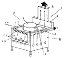
図1は本発明に係るガスレンジの一例での概略斜視図、図2はその概略側面図、図3は冷気(外気)循環ボックスの構成と温度上昇防止用天板の構成を示す斜視図、図4は左右側壁の一部を切欠したガスレンジの概略斜視図、図5は左右側壁の斜視図で、これら図において符号Aはガスレンジを示し、ステンレス等の鋼板で製作されたレンジ本体1内の下部にガスバーナー2を配置し、その上部に五徳(図示しない)を配置し、五徳に寸胴鍋3が載置される。
【0007】
レンジ本体1の後部壁4には排気口5が開口され、この排気口5に排気筒6が接続されている。
【0008】
図面符号8はレンジ本体1の左右側壁を示し、この左右側壁8は、二重壁体9によって構成され、この二重壁体9の間隙に冷気(外気)導入通路11が形成され、この二重壁体9の上端に框10が固装されている。
【0009】
図面符号12は温度上昇防止用天板を示し、この天板12に彎曲状切欠13が設けられている。
【0010】
図面符号14は冷気(外気)循環ボックスを示し、このボックス14の前板15には上下の冷気(外気)循環穴16が開口され、上板17に取手18が固装され、後板19は彎曲面20を形成している。
【0011】
図1,図2,図3,図4は、ガスバーナー2の五徳(図示しない)に寸胴鍋3を配置した状態を示しており、この寸胴鍋3の外周面をレンジ本体1の前部に取り付けられる冷気(外気)循環ボックス14の彎曲面20(後板19の彎曲面のこと)と、レンジ本体1の上面を覆う温度上昇防止用天板12の彎曲状切欠13が囲むかたちとなり、このような寸胴鍋3の配置態様をもって寸胴鍋3内のスープ等は、ガスバーナー2の燃焼によって煮沸されることになり、レンジ本体1内には、ガスバーナー2の排気熱が蓄熱する。
【0012】
然して、レンジ本体1内に蓄熱されるガスバーナー2の排気熱は、レンジ本体1の後部壁4に開口する排気口5に接続している排気筒6を介して、レンジフード7の方向に流れ、調理室内の壁に設置されるファン等を介して調理室の外部に排気させることができる。
【0013】
又、レンジ本体1の左右側壁8は二重壁体9を形成し、二重壁体9の間隙に冷気(外気)導入通路11が形成されている。そのため、左右側壁8の内側面がレンジ本体1内の排気熱により高温となっても、冷気(外気)導入通路11にレンジ本体下方からの冷気(外気)が流れ、その過程において左右側壁8の外表面が高温になるのを防ぐことができる。なお、前記冷気(外気)導入通路11内の冷気(外気)は、二重壁体9の上端に設けた框10の開口端より外部に排出される。
排気熱が厨房室内に拡散するのを抑制させる作用・効果がある。
【0014】
更に、レンジ本体1内の前部には冷気(外気)循環ボックス14が装着される。即ち、冷気(外気)循環ボックス14は、その前板15に上下の冷気(外気)循環穴16が開口されている(図4では、上穴23,下穴22)。このため、冷気(外気)循環ボックス14の内部21に冷気(外気)が流れる過程においてはレンジ本体1の前部側に排気熱が伝熱するのを防ぐことができ、また、レンジ本体1内の排気熱はレンジ本体1の後部壁4に開口した排気口5に接続される排気筒6を通過してレンジフード7方向に流れ、調理室内の壁に設置されるファン等を介して調理室の外部に排気可能となる。
【0015】
【発明の効果】
然して、本発明によれば、レンジ本体の前部(前カバー部分)に装着されている冷気(外気)循環ボックスの内部に冷気(外気)循環通路が形成され、この冷気(外気)循環通路を通過する過程の冷気(外気)の流れと冷気(外気)循環ボックス14の内部21に斉らされる空気断熱作用によってレンジ本体の前部側が高温になるのを防ぐことができる。
【0016】
また、この冷気(外気)循環ボックスに固装した取手の使用によって、冷気(外気)循環ボックスの装脱を容易にすることができ、更に、冷気(外気)循環ボックスの取外しによって寸胴鍋の取出しや、ガスバーナー、五徳、レンジ本体内部等の点検,保守,交換,掃除作業等を楽に行うことができる。
【0017】
しかも、レンジ本体の左右側壁を二重壁体の間隙に設けた冷気(外気)導入通路に対して、レンジ本体下方からの冷気(外気)が流入し、この冷気(外気)導入通路において生ずる冷気(外気)の流れの過程でレンジ本体の左右側壁の外表面が高温になるのを防ぐことができる。
【0018】
更に、本発明にあっては、レンジ本体内に配置される寸胴鍋の外周面を冷気(外気)循環ボックスの彎曲面(後部)と、温度上昇防止用天板の彎曲状切欠が囲み、レンジ本体の上面を温度上昇防止用天板が覆うかたちとなるので、寸胴鍋の外周面に沿って立ち上がるガスバーナーの排気熱がレンジ本体の上部に拡散していくのを防ぐことができ、そのため、寸胴鍋の加熱効率を良好に保てることができる。
【0019】
このように、本発明の実施態様によれば、調理現場の環境を悪化させるという懸念やレンジ本体の前部,左右側壁に調理従事者が触手しても火傷を被る等の危険を解消し、スープ等調理の安全性を確保することができる。
【0020】
【図面の簡単な説明】
【図1】 本発明に係るガスレンジの一例での概略斜視図である。
【図2】 同上の概略側面図である。
【図3】 冷気(外気)循環ボックスの構成と温度上昇防止用天板の構成を示す斜視図である。
【図4】 左右側壁の一部を切欠したガスレンジの概略図である。
【図5】 左右側壁の斜視図である。
【符号の説明】
A ガスレンジ
1 レンジ本体
2 ガスバーナー
3 寸胴鍋
4 後部壁
5 排気口
6 排気筒
7 レンジフード
8 左右側壁
9 二重壁体
10 框
11 冷気(外気)導入通路
12 温度上昇防止用天板
13 彎曲状切欠
14 冷気(外気)循環ボックス
15 前板
16 冷気(外気)循環穴
17 上板
18 取手
19 後板
20 彎曲面
21 内部
22 下穴
23 上穴[0001]
BACKGROUND OF THE INVENTION
The present invention relates to a gas range for cooking such as soup.
[0002]
[Prior art]
Conventional cooking gas ranges for soups, etc., are surrounded by a frame wall on the three or four sides of the range body with a built-in gas burner, etc., and directly contact the hot pot supported by the five virtues with the flame or hot gas from the gas burner etc. And made it possible to cook soups.
[0003]
[Problems to be solved by the invention]
However, in the gas range for the above-mentioned applications, exhaust heat from the gas burner or the like rising along the circumference of the small pan is diffused into the cooking chamber or the frame wall of the range body is overheated by the exhaust heat. Therefore, there is a problem that the temperature in the cooking chamber rises and the cooking environment in the cooking chamber is deteriorated.
[0004]
[Means for Solving the Problems]
The present invention has been made for the purpose of solving the above-described problems. Specifically, the invention according to
Means to prevent the frame wall of the range body from overheating due to the exhaust heat of the gas burner, etc., and the exhaust heat of the gas burner rising along the peripheral surface of the inked pan placed in the range body are at the top of the range body A gas range for cooking such as soup including means for preventing diffusion,
The former prevention means is formed by a cool air (outside air) circulation box that is detachably attached to the front of the range body, and a cold air (outside air) introduction passage between the double walls constituting the left and right side walls of the range body. And
The latter prevention means is constituted by the cold air (outside air) circulation box attached to the front part of the range body and the temperature rise prevention top plate covering the upper surface of the range body.
[0005]
The invention according to
[0006]
DETAILED DESCRIPTION OF THE INVENTION
Embodiments of the present invention will be described with reference to the drawings.
FIG. 1 is a schematic perspective view of an example of a gas range according to the present invention, FIG. 2 is a schematic side view thereof, and FIG. 3 is a perspective view showing the configuration of a cold air (outside air) circulation box and the configuration of a temperature rise prevention top plate. 4 is a schematic perspective view of a gas range with a part of the left and right side walls cut away, FIG. 5 is a perspective view of the left and right side walls. In these figures, symbol A indicates the gas range, and the
[0007]
An
[0008]
[0009]
Reference numeral 12 denotes a top plate for preventing temperature rise, and the top plate 12 is provided with a curved notch 13.
[0010]
Reference numeral 14 denotes a cold air (outside air) circulation box. Upper and lower cold air (outside air) circulation holes 16 are opened in the front plate 15 of the box 14, and a handle 18 is fixed to the
[0011]
1, 2, 3, and 4 show a state in which a small-
[0012]
However, the exhaust heat of the
[0013]
The left and
This has the effect of suppressing the diffusion of exhaust heat into the kitchen chamber.
[0014]
Further, a cold air (outside air) circulation box 14 is mounted on the front portion in the
[0015]
【The invention's effect】
However, according to the present invention, a cold air (outside air) circulation passage is formed inside the cold air (outside air) circulation box attached to the front portion (front cover portion) of the range body. It is possible to prevent the front side of the range body from becoming hot due to the flow of cold air (outside air) in the process of passing and the air heat insulation effect that is made uniform in the inside 21 of the cold air (outside air) circulation box 14.
[0016]
In addition, the use of a handle fixed to the cold air (outside air) circulation box makes it easy to attach and detach the cold air (outside air) circulation box. In addition, inspection, maintenance, replacement, and cleaning of the gas burner, virtues, the inside of the range body, etc. can be performed easily.
[0017]
Moreover, the cool air (outside air) from below the range body flows into the cool air (outside air) introduction passage in which the left and right side walls of the range body are provided in the gap between the double walls, and the cold air generated in the cold air (outside air) introduction passage. It is possible to prevent the outer surfaces of the left and right side walls of the range body from becoming hot during the course of (outside air) flow.
[0018]
Further, in the present invention, the outer peripheral surface of the size pan placed in the range body surrounds the curved surface (rear part) of the cold air (outside air) circulation box and the curved notch of the top plate for preventing temperature rise. Since the top surface of the main body is covered with a temperature rise prevention top plate, it is possible to prevent the exhaust heat of the gas burner rising along the outer peripheral surface of the short pan from diffusing to the top of the range body, The heating efficiency of the small pot can be kept good.
[0019]
Thus, according to the embodiment of the present invention, the risk of worsening the environment of the cooking site, the front of the range body, the risk of suffering burns even if the cooking worker touches the left and right side walls, The safety of cooking soups can be ensured.
[0020]
[Brief description of the drawings]
FIG. 1 is a schematic perspective view of an example of a gas range according to the present invention.
FIG. 2 is a schematic side view of the above.
FIG. 3 is a perspective view showing a configuration of a cold air (outside air) circulation box and a configuration of a top plate for preventing temperature increase.
FIG. 4 is a schematic view of a gas range in which a part of left and right side walls is cut away.
FIG. 5 is a perspective view of left and right side walls.
[Explanation of symbols]
A
Claims (2)
前者の防止手段はレンジ本体の前部に装脱自在に取り付けられる冷気(外気)循環ボックスと、レンジ本体の左右側壁を構成している二重壁体の間隙の冷気(外気)通路によって形成され、
後者の防止手段は、レンジ本体の前部に取り付けられる前記冷気(外気)循環ボックスと、レンジ本体の上面を覆う温度上昇防止用天板と、によって構成されることを特徴とするスープ等の調理用ガスレンジ。Means to prevent the frame wall of the range body from overheating due to the exhaust heat of the gas burner, etc., and the exhaust heat of the gas burner rising along the peripheral surface of the inked pan placed in the range body are at the top of the range body A gas range for cooking such as soup including means for preventing diffusion,
The former prevention means is formed by a cold air (outside air) circulation box that is detachably attached to the front of the range body, and a cold air (outside air) passage in the gap between the double walls constituting the left and right side walls of the range body. ,
The latter prevention means is composed of the cold air (outside air) circulation box attached to the front of the range body, and a temperature rise prevention top plate that covers the upper surface of the range body. Gas range.
Priority Applications (1)
| Application Number | Priority Date | Filing Date | Title |
|---|---|---|---|
| JP06058899A JP4038584B2 (en) | 1999-02-01 | 1999-02-01 | Gas range for cooking soup |
Applications Claiming Priority (1)
| Application Number | Priority Date | Filing Date | Title |
|---|---|---|---|
| JP06058899A JP4038584B2 (en) | 1999-02-01 | 1999-02-01 | Gas range for cooking soup |
Publications (3)
| Publication Number | Publication Date |
|---|---|
| JP2000217707A JP2000217707A (en) | 2000-08-08 |
| JP2000217707A5 JP2000217707A5 (en) | 2006-11-30 |
| JP4038584B2 true JP4038584B2 (en) | 2008-01-30 |
Family
ID=13146558
Family Applications (1)
| Application Number | Title | Priority Date | Filing Date |
|---|---|---|---|
| JP06058899A Expired - Fee Related JP4038584B2 (en) | 1999-02-01 | 1999-02-01 | Gas range for cooking soup |
Country Status (1)
| Country | Link |
|---|---|
| JP (1) | JP4038584B2 (en) |
Families Citing this family (11)
| Publication number | Priority date | Publication date | Assignee | Title |
|---|---|---|---|---|
| JP4225494B2 (en) * | 2004-05-25 | 2009-02-18 | ホシザキ電機株式会社 | Flyer |
| KR100625830B1 (en) * | 2005-03-30 | 2006-09-22 | 서선자 | Apparatus for discharging the smell in the lid of cooking receptacle |
| JP2011130987A (en) * | 2009-12-25 | 2011-07-07 | Osaka Gas Co Ltd | Cooker with tub |
| KR100979339B1 (en) * | 2010-03-05 | 2010-08-31 | 화신주방산업(주) | A caldron for cooking |
| JP5941829B2 (en) * | 2012-11-09 | 2016-06-29 | 株式会社マルゼン | Gas stove |
| JP5998039B2 (en) * | 2012-12-19 | 2016-09-28 | 株式会社マルゼン | Gas stove |
| CN104032933B (en) * | 2014-05-22 | 2016-08-17 | 同济大学 | A kind of pressure-balancing type kitchen twin shafts consentrated air supply smoke evacuation system device |
| CN106871164A (en) * | 2017-03-26 | 2017-06-20 | 六盘水市钟山区常冶金属加工厂 | A kind of gas air-return stove |
| CN112294109B (en) * | 2019-07-30 | 2021-12-24 | 安庆诚旺厨具科技有限公司 | Special flue system for noodle cooking machine |
| CN111520788B (en) * | 2020-05-29 | 2022-08-02 | 宁波方太厨具有限公司 | Control method of range hood |
| CN116025930B (en) * | 2023-02-06 | 2023-09-15 | 中山市艾利普电器有限公司 | Improved energy-saving electromagnetic oven |
-
1999
- 1999-02-01 JP JP06058899A patent/JP4038584B2/en not_active Expired - Fee Related
Also Published As
| Publication number | Publication date |
|---|---|
| JP2000217707A (en) | 2000-08-08 |
Similar Documents
| Publication | Publication Date | Title |
|---|---|---|
| JP4038584B2 (en) | Gas range for cooking soup | |
| US7059240B2 (en) | Double heating-type pots | |
| JP3629129B2 (en) | Liquid heating device | |
| JP4453907B2 (en) | Gas stove | |
| JP4182085B2 (en) | Gas burner and furnace | |
| JP2000217707A5 (en) | ||
| JP4758802B2 (en) | Gas stove | |
| JP4575255B2 (en) | Continuous rice cooker | |
| JP5758828B2 (en) | Five virtues | |
| JP5580698B2 (en) | Cooking equipment | |
| JP2005069546A (en) | Gas cooking stove | |
| JPH0531486Y2 (en) | ||
| JP3712463B2 (en) | Flame leak prevention stove | |
| JPH0533844Y2 (en) | ||
| JP3703950B2 (en) | Drop-in stove | |
| JPH11211089A (en) | Portable cooking stove with inner-flame-type burner | |
| JP2004100976A (en) | Gas range | |
| JP3230202B2 (en) | Stove | |
| JPH0112681Y2 (en) | ||
| KR100763241B1 (en) | Electric Cooking Sauce Cooker | |
| JPH09250751A (en) | Cooking stove capable of preventing leakage of flame | |
| JP6588411B2 (en) | Cooking pot | |
| JP3137472B2 (en) | Combustion equipment | |
| JPS5920806Y2 (en) | gas rice cooker | |
| JP3184952B2 (en) | Stove |
Legal Events
| Date | Code | Title | Description |
|---|---|---|---|
| A621 | Written request for application examination |
Free format text: JAPANESE INTERMEDIATE CODE: A621 Effective date: 20050926 |
|
| A521 | Written amendment |
Free format text: JAPANESE INTERMEDIATE CODE: A523 Effective date: 20060908 |
|
| A131 | Notification of reasons for refusal |
Free format text: JAPANESE INTERMEDIATE CODE: A131 Effective date: 20070515 |
|
| A521 | Written amendment |
Free format text: JAPANESE INTERMEDIATE CODE: A523 Effective date: 20070609 |
|
| TRDD | Decision of grant or rejection written | ||
| A01 | Written decision to grant a patent or to grant a registration (utility model) |
Free format text: JAPANESE INTERMEDIATE CODE: A01 Effective date: 20070911 |
|
| A61 | First payment of annual fees (during grant procedure) |
Free format text: JAPANESE INTERMEDIATE CODE: A61 Effective date: 20071016 |
|
| FPAY | Renewal fee payment (event date is renewal date of database) |
Free format text: PAYMENT UNTIL: 20101116 Year of fee payment: 3 |
|
| R150 | Certificate of patent or registration of utility model |
Free format text: JAPANESE INTERMEDIATE CODE: R150 |
|
| FPAY | Renewal fee payment (event date is renewal date of database) |
Free format text: PAYMENT UNTIL: 20101116 Year of fee payment: 3 |
|
| FPAY | Renewal fee payment (event date is renewal date of database) |
Free format text: PAYMENT UNTIL: 20101116 Year of fee payment: 3 |
|
| FPAY | Renewal fee payment (event date is renewal date of database) |
Free format text: PAYMENT UNTIL: 20101116 Year of fee payment: 3 |
|
| FPAY | Renewal fee payment (event date is renewal date of database) |
Free format text: PAYMENT UNTIL: 20131116 Year of fee payment: 6 |
|
| R250 | Receipt of annual fees |
Free format text: JAPANESE INTERMEDIATE CODE: R250 |
|
| R250 | Receipt of annual fees |
Free format text: JAPANESE INTERMEDIATE CODE: R250 |
|
| R250 | Receipt of annual fees |
Free format text: JAPANESE INTERMEDIATE CODE: R250 |
|
| LAPS | Cancellation because of no payment of annual fees |