JP4038541B2 - Heat treatment method for steel wire - Google Patents
Heat treatment method for steel wire Download PDFInfo
- Publication number
- JP4038541B2 JP4038541B2 JP2004066582A JP2004066582A JP4038541B2 JP 4038541 B2 JP4038541 B2 JP 4038541B2 JP 2004066582 A JP2004066582 A JP 2004066582A JP 2004066582 A JP2004066582 A JP 2004066582A JP 4038541 B2 JP4038541 B2 JP 4038541B2
- Authority
- JP
- Japan
- Prior art keywords
- wire
- heating
- heat treatment
- quenching
- cross
- Prior art date
- Legal status (The legal status is an assumption and is not a legal conclusion. Google has not performed a legal analysis and makes no representation as to the accuracy of the status listed.)
- Expired - Fee Related
Links
Images


Classifications
-
- Y—GENERAL TAGGING OF NEW TECHNOLOGICAL DEVELOPMENTS; GENERAL TAGGING OF CROSS-SECTIONAL TECHNOLOGIES SPANNING OVER SEVERAL SECTIONS OF THE IPC; TECHNICAL SUBJECTS COVERED BY FORMER USPC CROSS-REFERENCE ART COLLECTIONS [XRACs] AND DIGESTS
- Y02—TECHNOLOGIES OR APPLICATIONS FOR MITIGATION OR ADAPTATION AGAINST CLIMATE CHANGE
- Y02P—CLIMATE CHANGE MITIGATION TECHNOLOGIES IN THE PRODUCTION OR PROCESSING OF GOODS
- Y02P10/00—Technologies related to metal processing
- Y02P10/25—Process efficiency
Landscapes
- Metal Extraction Processes (AREA)
- Heat Treatment Of Strip Materials And Filament Materials (AREA)
Description
本発明は、焼入焼戻し鋼線の製造方法に関するものである。 The present invention relates to a method for producing a quenched and tempered steel wire.
焼入焼戻し鋼線はばね用、コンクリート補強用、機械部品等に広く使用されている。一般的製造方法は、熱間圧延線材を材料にしてまず製品径まで伸線加工しコイル状の中間材とする。次ぎに該コイルを連続熱処理装置に供給し、直線状に走行させ全長を同一条件で加熱、焼入、焼戻しした後再びコイル状に巻き取り製品コイルとする。このプロセスを実施する際、2方式が競合している。 Quenched and tempered steel wire is widely used for springs, concrete reinforcement, machine parts, etc. A general manufacturing method uses a hot-rolled wire as a material and first draws it to the product diameter to obtain a coiled intermediate material. Next, the coil is supplied to a continuous heat treatment apparatus, is linearly run, heated, quenched, and tempered under the same conditions, and then wound into a coil again to obtain a product coil. Two schemes are competing when performing this process.
第1の方法は、低速多ストランド方式と称され、複数の中間材を同時平行処理するもので、通常火炎式加熱炉、油焼入槽、焼戻し炉の順に通過させそれぞれ個別の巻取機に巻き取られる。第2の方法は高速単ストランド方式で、1本の中間材を高速で上記処理する。加熱方法として高周波誘導加熱又は直接通電加熱等が使用される。10mm径前後の太径製品には有力な方法である。本方法は急熱による結晶粒微細化と平滑美麗な表面等製品品質には有利であるが、電力、人件費等操業コスト及び設備コストが割高である。特に鋼種、品種、寸法が多種多様なばね用や機械部品用の鋼線等の製造に適用すると、工程切り替えが頻繁になる。さらに今日の短納期、在庫削減に対処する小ロット生産が重なると生産能率・設備能力の半減、歩留まりの低下、作業工数の増大等問題が大きい。 The first method is called a low-speed multi-strand system, and processes a plurality of intermediate materials in parallel. Usually, a flame-type heating furnace, an oil quenching tank, and a tempering furnace are passed through each in the order of individual winders. It is wound up. The second method is a high-speed single-strand method, in which one intermediate material is processed at a high speed. As a heating method, high-frequency induction heating or direct current heating is used. This is an effective method for large-diameter products around 10 mm in diameter. This method is advantageous for product refinement such as crystal grain refinement and smooth and beautiful surface by rapid heating, but operation cost and equipment cost such as electric power and labor cost are expensive. In particular, when applied to the manufacture of steel wires for springs and machine parts having a wide variety of steel types, varieties, and dimensions, process switching is frequent. In addition, today's short delivery times and small lot production to cope with inventory reductions have many problems such as halving production efficiency and equipment capacity, lowering yield, and increasing work man-hours.
どちらの熱処理方式を採用しても、焼入焼戻し鋼線の製造コスト上の大きな負担は、熱処理に先行して伸線工程が不可欠となっていることである。その第1の理由は、熱間圧延線材の寸法は段階的に集約、標準化されているが鋼線寸法は任意に設定されるためであり、第2の理由は、鋼線寸法の許容範囲は小さく、熱間圧延ではその精度に到達できないからである。偏径差(=断面の長径・短径差)についても全く同様である。
第3の理由は、熱間圧延線材には多少なりとも表面傷が残存する。そのため伸線工程では通常、探傷検査により手入れ、処置がなされる。伸線を省略すると当該作業が熱処理工程に持ち込まれ生産性を阻害する。以上のように熱延線材をそのまま焼入焼戻し鋼線用に使用することは現在では至難の技である。
Regardless of which heat treatment method is employed, a major burden on the manufacturing cost of the quenched and tempered steel wire is that the wire drawing step is indispensable prior to the heat treatment. The first reason is that the dimensions of hot-rolled wire rods are aggregated and standardized in stages, but the steel wire dimensions are arbitrarily set, and the second reason is that the allowable range of the steel wire dimensions is This is because it is small and the accuracy cannot be reached by hot rolling. The same is true for the difference in eccentric diameter (= difference between major axis and minor axis of the cross section).
The third reason is that some surface scratches remain in the hot-rolled wire. For this reason, in the wire drawing process, care and treatment are usually performed by flaw detection inspection. If the wire drawing is omitted, the operation is brought into the heat treatment process and the productivity is hindered. As described above, it is extremely difficult to use a hot-rolled wire as it is for a quenched and tempered steel wire.
生産性問題の他に、焼入焼戻し鋼にはつきものの慢性的材質問題として”遅れ破壊”が挙げられる。これは応力下における含有Hの特異な挙動により製造直後より材料欠陥部が徐々に拡大し、破壊に到る現象である。対策として溶鋼精錬における真空脱ガスの適用や、製品熱処理後に再び低温時効熱処理の附加等がなされコスト増等問題が大きい。 In addition to productivity problems, “delayed fracture” is an inherent chronic material problem in hardened and tempered steel. This is a phenomenon in which the material defect portion gradually expands immediately after production due to the unique behavior of the contained H under stress, leading to destruction. As countermeasures, the application of vacuum degassing in molten steel refining, and the addition of low-temperature aging heat treatment after product heat treatment, etc. are serious problems such as cost increase.
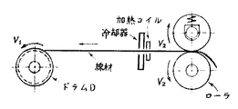
上記問題の部分解決に応用できそうな研究が文献1、文献2に詳述されている。提起された新プロセスのダイレス引抜はダイス等工具を一切使用せずに引抜を行うものである。図3に示すように鋼線に一定の張力を作用させつつ走行させ、局所的に誘導加熱により急熱し直後に急冷することによって高温部で延伸させる。本プロセスの特徴・要点を以下に示す。
1) 加工前後の鋼線の断面積比は加工前後の線速比に正確に反比例し、加工前後の鋼線の断面形状は正確に相似である。
2) 減面率40%以上の加工が可能であり、熱的条件を適切に制御することにより硬化、軟化等の熱処理の付加が可能である。
3) 当該メカニズムの第1の安定化条件は、延伸直前・直後の変形抵抗比(加工後/加工前、低温側/高温側)は断面積比(加工前/加工後)を上回らなければならない。即ち冷却の強さにある。条件が外れると低温側で破断する。
4) 第2の安定化条件は、加熱部と急冷部を接近させなければならない。条件が外れると高温側で絞り切れが発生する。理由は、速度差に対応して高温部が延伸する。冷却タイミングが遅れると単純な熱間引張加工になる。最初に延伸した部分の応力が延伸に反比例して増加するのに対して加工硬化は途中で追いつかれ、又冷却による硬化も遅れる。結果、該延伸部のみに歪みが集中するからである。
1) The cross-sectional area ratio of the steel wire before and after processing is exactly inversely proportional to the wire speed ratio before and after processing, and the cross-sectional shape of the steel wire before and after processing is exactly similar.
2) Processing with a reduction in area of 40% or more is possible, and heat treatment such as hardening and softening can be added by appropriately controlling the thermal conditions.
3) The first stabilization condition of the mechanism is that the deformation resistance ratio (after processing / before processing, low temperature side / high temperature side) immediately before and after stretching must exceed the cross-sectional area ratio (before processing / after processing). . That is, it is in the strength of cooling. If the conditions are not met, it breaks on the low temperature side.
4) As for the 2nd stabilization conditions, a heating part and a quenching part must be brought close. If the conditions are not met, the drawing out occurs on the high temperature side. The reason is that the high temperature portion is stretched corresponding to the speed difference. When the cooling timing is delayed, a simple hot tensile process is performed. While the stress of the first stretched portion increases in inverse proportion to the stretching, work hardening is caught up in the middle, and hardening by cooling is also delayed. As a result, strain concentrates only on the stretched portion.
上記ダイレス引抜を高速単ストランドの焼入焼戻しラインに適用して製品線径の自在変更可能になれば好都合であるが、多くの問題が予測される。
A) 上記研究における実験条件の1桁大きい速度で上記プロセスを安定させなければならない。増速の結果、加熱部、延伸部、冷却部はそれぞれ走行方向に拡張する。特に加熱部の拡張は第2条件に対して不都合に作用する。誘導加熱能力の強化で対処すると表皮の過熱をもたらす。高速化への対処が困難且つ未知であることが当該プロセスが未だ生産に供されていない大きな理由である。
It would be advantageous to apply the dieless drawing to a high-speed single strand quenching and tempering line so that the product wire diameter can be freely changed, but many problems are expected.
A) The process must be stabilized at an order of magnitude greater than the experimental conditions in the study. As a result of the speed increase, the heating part, the extending part, and the cooling part are each expanded in the traveling direction. In particular, the expansion of the heating unit adversely affects the second condition. Dealing with the enhancement of induction heating capacity leads to overheating of the epidermis. The fact that it is difficult and unknown to cope with high speed is a major reason that the process has not yet been put into production.
B) ダイレス加工のための適正熱的条件と本来の熱処理条件が整合しなければならない。問題の例1として、通常、加熱工程ではオーステナイト化した後、炭化物溶体化のための適度の保持がなされている。これは上記第2条件にそぐわない。例2として、エネルギー効率が高く均熱性に優れた直接通電方式の加熱は電極スペース等構造上、上記第2条件には適応できない。 B) Appropriate thermal conditions for dieless processing must match the original heat treatment conditions. As Example 1 of the problem, usually, in the heating process, after austenitization, moderate holding for carbide solution is performed. This does not meet the second condition. As Example 2, direct energization heating with high energy efficiency and excellent thermal uniformity cannot be applied to the second condition because of the structure of the electrode space and the like.
C) 製品断面寸法の管理に対して、熱的、機械的な要因の変動により従来には無かった軸方向変動が新たに加わる。
D) 延伸による縮径が適切に制御できても材料の偏径差は解消されない。即ち熱延線材の直接使用には無理がある。
E) 一種の加工熱処理となるので金属組織や表面性状が従来製品とは異なる。材質上の問題が解らないと言う問題がある。
C) For the management of product cross-sectional dimensions, there is a new axial variation that did not exist in the past due to variations in thermal and mechanical factors.
D) Even if the diameter reduction by stretching can be controlled appropriately, the difference in diameter of the material is not eliminated. That is, it is impossible to use the hot-rolled wire directly.
E) Since it is a kind of thermomechanical processing, the metal structure and surface properties are different from the conventional products. There is a problem that the material problem is not understood.
他方、未解決の遅れ破壊問題に対して、近年文献3において改良オースフォーム処理(熱間加工直後に焼入焼戻しする方法)が該問題の解決に有効と解明された。当該技術の応用に際する問題は、オースフォーム処理(過冷オーステナイトの加工+焼入焼戻し)は古い技術であるが煩雑故に特定鋼材以外は実用されていない。上記研究においても複数パスの熱間圧延の先行処理を要し、既存の焼入焼戻しラインに挿入するには同様に極めて煩雑になる。
On the other hand, for the unresolved delayed fracture problem, in recent years, it has been elucidated in
本発明は従来の焼入焼戻し鋼線の熱処理方法における問題即ち以下の項目を解決すべき課題としている。
1) 熱処理ライン内で一定の直径の中間材から種々の直径の焼入焼戻し鋼線を無停止操業で効率的に造り分け、生産性向上を図る。
2) 中間材を造る伸線工程を省略し、熱間圧延線材を直接、熱処理用の材料として使用し、コスト削減を図る。
3) 耐遅れ破壊性を改善する。
The present invention addresses the problems in the conventional heat treatment method for quenched and tempered steel wires, that is, the following items.
1) In the heat treatment line, hardened and tempered steel wires of various diameters are efficiently formed from non-fixed intermediate materials in a non-stop operation to improve productivity.
2) Omit the wire drawing process to make the intermediate material and use the hot-rolled wire directly as the material for heat treatment to reduce the cost.
3) Improve delayed fracture resistance.
上記の大きな3課題を解決するため以下の問題の解決策を提供する。
a) ダイレス引抜を実用化する。
b) そのため現行熱処理条件とダイレス引抜の熱的・機械的条件を整合させる。
c) 高速ダイレス引抜の安定化方法を考案する。
d) 耐遅れ破壊性改善のためのオースフォーム処理を実施容易とする。
e) 材料間の溶接をライン無停止で実施できるよう材料供給方式を改善する。
f) 熱延線材に不可避の偏径差不適合をライン内で解消する。
g) 稼働率向上のため製品断面の寸法基準を合理的に改善する。
h) 断面寸法制御に外れた部分を効率的に排除する。
i) 熱延線材に不可避の表面傷を効率的に処理する。
In order to solve the above three major problems, the following solutions are provided.
a) Practical use of dieless drawing.
b) Therefore, the current heat treatment conditions are matched with the thermal and mechanical conditions of dieless drawing.
c) Devise a stabilization method for high-speed dieless drawing.
d) Ausfoam treatment for improving delayed fracture resistance is easy to implement.
e) Improve the material supply system so that welding between materials can be performed without stopping the line.
f) Eliminating inconsistencies in the deviation in diameter that are unavoidable with hot-rolled wires.
g) Reasonably improve product cross-sectional dimension standards to improve availability.
h) Efficiently eliminate the part outside the cross-sectional dimension control.
i) Efficiently treats inevitable surface flaws on hot-rolled wire.
上記課題を解決するため、材料、伸線、熱処理、ばね加工を総合検討して以下の指針を得た。第1に熱処理と加工の整合に対しては、主として熱処理のための1次加熱と主としてダイレス引抜のための2次加熱の2段加熱法を着想し、適用した。第2にダイレス引抜は条件次第でオースフォーム、改良オースフォームを包含することに気づいた。両技術を統合して2段加熱に伴う適正金属組織からの偏りに対してはオースフォーム効果で解消するという新規の策に期待し、引張試験機を使用した簡単な予備的試験でその効果を確認した。その結果確信を持ってダイレス引抜とオースフォーム処理の適合を進めることとなった。第3に2段加熱法はダイレス引抜の高速化条件に対しても適切であることが明らかとなった。第4に伸線工程の省略に当たって、熱延線材に不可避の偏径差を解消するためダイレス引抜機構の上流側にダイス引抜を巧みに付加した。第5に高速ダイレス引抜の寸法制御に関して、従来の製品寸法仕様の規定・意図を尊重しつつ必要にして充分な新規の寸法、断面積規定がより合理性があることを解明し且つ適用し稼働率向上に役立てた。第6にメカニズムが従来より複雑になること且つ熱延線材を直接使用することから場合により不良が増加する。対策として下流のばね加工工程を含めた不良部の排除システムを考案し本プロセス全体の信頼性を上げた。 In order to solve the above problems, the following guidelines were obtained by comprehensively examining materials, wire drawing, heat treatment, and spring processing. First, for the matching of heat treatment and processing, a two-step heating method of primary heating mainly for heat treatment and secondary heating mainly for dieless drawing was conceived and applied. Secondly, it was found that dieless drawing includes aus forms and modified aus forms depending on the conditions. Expecting a new measure to eliminate the bias from the appropriate metal structure due to the two-stage heating by integrating both technologies with the Ausfoam effect, the effect is achieved by a simple preliminary test using a tensile tester. confirmed. As a result, we decided to proceed with dieless drawing and ausfoam processing with certainty. Thirdly, it has been clarified that the two-stage heating method is appropriate for the speed-up conditions of dieless drawing. Fourthly, in order to eliminate the wire drawing step, a die drawing was skillfully added to the upstream side of the dieless drawing mechanism in order to eliminate the inevitable deviation in the diameter of the hot-rolled wire. Fifth, with regard to dimensional control of high-speed dieless drawing, we have clarified, applied and operated the new dimensions and cross-sectional area specifications that are necessary and sufficient while respecting the specifications and intentions of conventional product dimensional specifications. It helped to improve the rate. Sixth, since the mechanism becomes more complicated than before and the hot-rolled wire is used directly, the number of defects may increase. As a countermeasure, we devised a system for eliminating defective parts, including the downstream spring machining process, and improved the reliability of the entire process.
本発明の第1は、鋼線材を直線状に走行させ全長を同一条件で加熱、焼入、焼戻しするライン式連続熱処理方法において、それぞれ、1)該線材に張力を作用させ該線材の高温部において断面積を20%以上縮小させるダイレス引抜を行い、2)該張力を与える方法が、加熱の上流側と焼入の下流側にそれぞれ配置された二つの線材送給装置の速度差によってなされ、3)加熱する方法が、AC3点上50℃以上、150℃以下に1次加熱した後、冷却・焼入部位の上流側直近において高周波誘導加熱により該1次加熱温度より50℃以上、250℃以下の高温へ急速に2次加熱することからなり、4)焼入冷却速度と冷却時間をダイレス引抜と焼入に対してそれぞれ必要な大きさの大きい方以上とし、 5)製品断面寸法を調整する方法が、縮小前後の断面積比を該両線材送給装置の速度比に反比例させる
ことによってなされる、ことを特徴とする鋼線材の連続熱処理方法である。
The first of the present invention is a line-type continuous heat treatment method in which a steel wire travels linearly and is heated, quenched, and tempered under the same conditions. 1) A high temperature part of the wire is made to act on the wire. 2) A method of applying the tension to reduce the cross-sectional area by 20% or more is performed by the difference in speed between the two wire feeding devices arranged on the upstream side of heating and the downstream side of quenching, 3) The method of heating is 50 ° C. or more and 250 ° C. higher than the primary heating temperature by high-frequency induction heating in the immediate vicinity of the upstream side of the cooling / quenching part after primary heating to 50 ° C. or more and 150 ° C. or less on the AC3 point. It consists of rapid secondary heating to the following high temperatures: 4) The quenching cooling rate and cooling time are set to be larger than the larger one required for dieless drawing and quenching, respectively. 5) Product cross-sectional dimensions are adjusted. How to It is a continuous heat treatment method for steel wire, characterized in that the cross-sectional area ratio before and after reduction is made inversely proportional to the speed ratio of the both wire feeders.
第2の発明は、両線材送給装置の速度比を連続的に変更して新所定値に再設定することにより製品径を変更する方法によって、過渡期部分を除き一定の直径の線材から種々の直径の鋼線を無停止で造り分けることを特徴とする第1発明に記載の連続熱処理方法である。 According to a second aspect of the present invention, there is provided a method for changing a product diameter by continuously changing a speed ratio of both wire feeding devices and resetting the speed to a new predetermined value. The continuous heat treatment method according to the first aspect of the present invention is characterized in that steel wires having a diameter of 5 mm are formed without stopping.
第3の発明は、供給される鋼線材が熱間圧延線材であり、該線材コイルを静置した状態で一端を該コイルの軸方向に引き出してラインに供給し、上流側線材送給装置は1個の引抜ダイス(重ねダイスを含む)とキャプスタンからなり、該線材送給装置により該線材をダイス引抜して真円又は楕円又は卵形のいずれかの形状に成形することを特徴とする第1又は第2の発明に記載の連続熱処理方法である。 According to a third aspect of the present invention, the steel wire to be supplied is a hot-rolled wire, and with the wire coil stationary, one end is pulled out in the axial direction of the coil and supplied to the line. It consists of a single drawing die (including overlapping dies) and a capstan, and is characterized in that the wire is die-drawn by the wire feeding device and shaped into a perfect circle, ellipse or egg shape. It is the continuous heat processing method as described in 1st or 2nd invention.
第4の発明は、焼入と焼戻し間で検知・算出された断面積が規格範囲を外れた場合、又は同区間で表面欠陥が検知された場合、それぞれ当該部分に対して焼戻し温度を所定値より50℃以上、100℃以下の高温に変更して過剰軟化させることを特徴とする第1又は第2又は第3の発明に記載の連続熱処理方法である。 In the fourth aspect of the present invention, when the cross-sectional area detected and calculated between quenching and tempering is out of the standard range, or when a surface defect is detected in the same section, the tempering temperature is set to a predetermined value for the corresponding part. more 50 ° C. or higher, a first or second or third continuous heat treatment method according to the invention is characterized in 100 ° C. to cause excessive softening is changed to a high temperature of below.
本発明によると、第1に一定の直径の伸線された中間材からそれより細い種々の直径の焼入焼戻し鋼線を無停止、連続的且つ効率的に造り分けることができる。従来の製品寸法仕様は合理的に緩和され、歩留まり、稼働率、作業能率、設備能力の向上等を通してコスト低減が図られる。 According to the present invention, a hardened and tempered steel wire having various diameters thinner than that of a drawn intermediate material having a constant diameter can be produced without interruption, continuously and efficiently. Conventional product dimensional specifications are rationally relaxed, and costs can be reduced through improvements in yield, operating rate, work efficiency, and facility capacity.
第2に、煩雑であったオースフォーム処理が容易に従来の焼入焼戻しラインに組み込まれる。その結果焼入焼戻し鋼の慢性材料問題であった耐遅れ破壊性の向上が充分期待される。 Secondly, the complicated ausfoam treatment is easily incorporated into a conventional quenching and tempering line. As a result, the delayed fracture resistance, which has been a chronic material problem in quenched and tempered steel, is expected to be sufficiently improved.
第3に、中間材の代わりに熱間圧延線材を直接使用することが可能になり、コストの大幅削減の他、造り分けと伸線省略を通して納期が短縮される。 Thirdly, it becomes possible to directly use a hot-rolled wire instead of an intermediate material, and the delivery time is shortened through manufacturing and omission of wire drawing in addition to significant cost reduction.
熱延線材の直接使用に伴う新たな品質欠陥の誘発に対しては、下流のばね加工等の成形工程と統合した排除システムにより不良部分のみが確実に除去されるので総合歩留まりが向上するとともに新プロセスの信頼性が向上する。 For the induction of new quality defects due to the direct use of hot-rolled wire, only the defective part is reliably removed by the removal system integrated with the molding process such as downstream spring processing, so the overall yield is improved and new Improves process reliability.
図1は第1から第4の発明の焼入焼戻し方法を実施する装置を例示する概略側面図である。図2は図1に示した方法の代替方法の例を示す。以下、すべての要素を網羅する第4発明を図面に従って説明する。
材料として円断面の熱間圧延線材2が使用され、コイル架台1に静置された該線材2のコイルの一端がコイル軸方向に引き出され焼入焼戻しライン3に供給される。この繰り出し方式は一般にデッド・サプライと言われる。該ラインは順次下流に向けて、脱膜装置4、引抜ダイス5、キャプスタン6、1次加熱装置7、2次加熱装置8、冷却装置9、鋼線プロフィルメーター10、ピンチロール11、探傷器12、焼戻し装置13、焼戻し冷却装置14及び巻取機15から成る。
FIG. 1 is a schematic side view illustrating an apparatus for carrying out the quenching and tempering methods of the first to fourth aspects of the invention. FIG. 2 shows an example of an alternative method to the method shown in FIG. The fourth invention covering all elements will be described below with reference to the drawings.
A hot-rolled
処理される線材2はまずショット・ブラスト等の脱膜装置4を通過して表面の酸化膜が除去され引抜の予備処理がなされる。次ぎに引抜ダイス5とキャプスタン6により1パスの引抜加工がなされ線材2の断面が真円もしくは所定の異形になる。該キャプスタン6は上流側線材送給装置の機能も併せ持つ。該線材2は下流側線材送給装置であるピンチロール11によりキャプスタン6の周速より大きい速度で引っ張られながら走行する。中間材を使用する場合は上記ダイス引抜機構は不要で、上流側線材送給装置だけでよい。
The
次ぎに該線材2は通常のソレノイド型高周波加熱コイルからなる1次加熱装置6を貫通しA C3 点の上方、50℃以上、150℃以下に加熱され、短時間保持される。当該温度は焼入に適切な通常の温度範囲の下限近傍である。材料の金属組織はオーステナイトとなる。次ぎに該線材2は通常のソレノイド型高周波加熱コイルからなる2次加熱装置8を貫通して1次加熱温度上50℃以上、250℃以下に過熱され、一層軟化する。張力により延伸が発生する。
Next to該線
次ぎに該線材2は2次加熱装置8に接近配置された強力な水冷ノズルからなる冷却装置9を貫通し冷却される。変形抵抗が増加して延伸が停止しその後焼入が進む。冷却速度と冷却時間は完全焼入に対しても又ダイレス加工に対しても必要・充分な大きさに設定されている。該線材2は2次加熱装置8と冷却装置9間の狭い部分のみで延伸する。その結果通常の焼入とは異なるオースフォーム処理を受けることになる。断面形状は延伸前後で相似となる。
Next, the
キャプスタン6、ピンチロール11ともスリップが生じないよう設計・維持されているので、延伸前後の断面積比は延伸前後の速度比に正確に反比例する。従って速度比のみの設定により線材2を所望の鋼線径に加工することができる。
製品径を変更する場合、該速度比を連続的に変更して変更後の直径に適合する所定速度比に再設定する。このようにして一定の直径の材料からそれより細い種々の直径の鋼線を過渡期部分を除いて連続的に造り分けることができる。
Since both the
When the product diameter is changed, the speed ratio is continuously changed and reset to a predetermined speed ratio that matches the changed diameter. In this way, steel wires of various diameters thinner than that can be continuously formed from a material having a constant diameter, excluding the transition period.
ピンチロール11の上流側には鋼線プロフィルメーター10が配置され、加工の状況を監視する。計測・算出された断面積に対応してピンチロール11の速度が速度制御器18を介して微調整され、該断面積は通常は基準値の±2.0%以内に制御される。ここで基準値とは線径が規格中心値の場合の断面積である。許容幅の値は線径許容値(通常±1.0%)に対応している。異形断面についても同様である。
A steel
所定範囲の寸法になった線材はその後表面傷を検出する探傷器12、誘導加熱による焼戻し装置13、水冷ノズルで構成された焼戻し冷却装置14を経て焼入焼戻し鋼線16となり、巻取り機15により製品コイルとされる。鋼線プロフィルメーター10による断面形状測定において、寸法が管理範囲を超えた部分に対しては、焼戻し温度を焼戻し制御器19を介して所定温度(鋼種、サイズにより異なり、通常430℃以上、530℃以下)より50℃ないし100℃上昇させて過剰軟化させる。即ち寸法不良部を強度不良部に包含させて、後述のように後工程で排除する。
The wire rod having a dimension within a predetermined range then becomes a quenched and tempered
熱延線材を直接使用する場合、既述のように表面傷の残存が問題となる。探傷器12によって表面傷が検出された部分に対しても上記同様に過剰軟化させ且つ同様に処理する。軟化度は特に厳密性を要するものではない。
When the hot-rolled wire is used directly, the remaining surface scratches are a problem as described above. The portion where the surface flaw is detected by the
以上に説明した実施方法において種々の代替手段が考えられる。図2に従い、例えば線材送給装置としてキャプスタン6の代わりにエンドレス・ベルト式駆動装置21を使用することができる。1次加熱に対しては、誘導加熱にかえ直接通電加熱装置22を使用すると熱効率が向上する。この場合、通電安定化のため脱膜装置20により予め酸化膜を除去しておく。ダイス引抜に代えて軽圧下圧延機23を適用する方法もある。断面プロフィルメーターとして、市販の旋回機構を保有するレーザー測長器にかえ、図2の固定式プロフィルメーター24のように測長センサーを数点固定配置して計測する方法もある。断面は真円と前提して1点測定測長センサーで済ませることもできる。
Various alternatives are conceivable in the implementation method described above. According to FIG. 2, for example, an endless belt
線材2をラインに供給するに当たり、デッド・サプライ方式と限定した理由は以下である。第1の理由は、ラインが稼働中でも線材はコイル架台1に静置されているのでコイル毎の溶接が容易で無停止操業を可能にする。第2の理由は、伸線された中間材の強度は約1500MPaに増大し、線径が大きい場合には捻り抵抗のためデッドサプライは困難であるが、熱延線材のそれは1000MPa程度で比較的容易に可能となるからである。
The reason for limiting the dead supply method to supplying the
次ぎに加熱を2段階にした理由は以下である。第1に、ダイレス引抜安定化のためには冷却直前のみを高温軟化させねばならない。他方正常な焼入加熱には上限温度があり且つ適正な保持が必要である。両条件の整合のため1次加熱として既述のように焼入に必要な最低限の温度と時間を確保し、2次加熱として1次より高温でダイレス引抜の適正温度域とし且つ焼入に対して多少不適切になってもオースフォーム効果により解消し得る温度とした。
第2の理由は、ダイレス引抜の高速化に際して、既述の安定化2条件を厳守するにはライン方向に拡張する加熱・冷却帯を極力短縮することが不可欠であり、必然的に実効加熱帯長を限定し得る2段加熱にならざるを得ないことである。
Next, the reason why the heating is performed in two stages is as follows. First, in order to stabilize the dieless drawing, it is necessary to soften at high temperature only just before cooling. On the other hand, normal quenching heating has an upper limit temperature and must be properly maintained. As described above, the minimum temperature and time required for quenching are secured as the primary heating for matching both conditions, and the appropriate temperature range for dieless drawing is set as the secondary heating at a temperature higher than the primary and for quenching. On the other hand, even if it became somewhat inappropriate, the temperature was set so that it could be eliminated by the ausfoam effect.
The second reason is that, when speeding up the dieless drawing, it is indispensable to shorten the heating / cooling zone that extends in the line direction as much as possible in order to strictly observe the above-mentioned
1次加熱温度は対象鋼種のAC3点上50℃以上、150℃以下とした理由は、前記焼入に必要な最低限の温度と2次加熱とを合わせて適正溶体化条件とするためである。2次加熱は1次加熱温度上の50℃以上、250℃上に過熱されるが、その程度は主に加工度に依存する。低加工度なら低過熱でよい。高加工度で低過熱なら変形抵抗の低下不足により延伸が上流に及ぶ危険性が生ずる。250℃を超えると2次加熱後の保持時間が無いとは言えオーステナイト結晶粒が不均一、不適切に成長し易く不都合である。過熱度をこのように大きくできる根拠は、高加工度ほど結晶粒微細化を通してオースフォーム効果により上記問題を解消できるからである。減面率を20%以上と特定した理由は、オースフォーム効果を得るため減面率は少なくとも20〜25%必要であるからである。 The reason why the primary heating temperature is set to 50 ° C. or higher and 150 ° C. or lower on the AC3 point of the target steel type is to combine the minimum temperature necessary for the quenching and the secondary heating to obtain an appropriate solution condition. . The secondary heating is overheated to 50 ° C. or higher and 250 ° C. above the primary heating temperature, and the degree mainly depends on the degree of processing. If the degree of processing is low, low overheating is sufficient. If the degree of processing is high and the degree of superheat is low, there is a risk that the stretching may be upstream due to insufficient deformation resistance. If it exceeds 250 ° C., the austenite crystal grains are not uniform and are likely to grow improperly, although there is no holding time after secondary heating. The reason why the degree of superheat can be increased in this way is that the higher the degree of work, the more the above problem can be solved by the Ausfoam effect through crystal grain refinement. The reason for specifying the area reduction rate as 20% or more is that the area reduction rate needs to be at least 20 to 25% in order to obtain the Ausfoam effect.
冷却速度及び冷却時間をダイレス引抜と焼入に対してそれぞれ必要な大きさの大きい方以上と限定した第1の理由は、両プロセスにそれぞれ適切な冷却速度・時間自体は鋼種、線径、延伸比、焼き割れなどの異常品質防止等により色々異なるが、多少困難があっても品質上両立が不可欠であるからである。
第2の理由は、前述した2次加熱と該冷却部における強力な冷却の相互作用により延伸帯を極力縮小、加工時間を短縮して加工組織の再結晶を抑制し、オースフォーム効果を逃がさないためである。
The first reason for limiting the cooling rate and cooling time to the larger one required for dieless drawing and quenching is that the appropriate cooling rate and time for both processes are the steel type, wire diameter, and drawing. This is because it is indispensable in terms of quality even if there are some difficulties, although it varies depending on the ratio and abnormal quality prevention such as burn cracking.
The second reason is that the stretch zone is reduced as much as possible by the interaction between the secondary heating described above and the strong cooling in the cooling section, the processing time is shortened, the recrystallization of the processed structure is suppressed, and the ausforming effect is not lost. Because.
上流側線材送給装置をキャプスタンと特定した理由は、ダイス引抜には簡便・最適であり、ダイレス引抜に対しても充分な張力を生む摩擦力が容易に得られ、共用できるからである。 The reason for specifying the upstream wire feeding device as a capstan is that it is simple and optimal for die drawing, and a frictional force that generates sufficient tension for dieless drawing can be easily obtained and shared.
次ぎに伸線工程を経た従来の焼入焼戻し鋼線が、熱延線材をダイス引抜・ダイレス引抜・オースフォームの三つを組み合わせた工程により製造された本発明の鋼線に代替される根拠をばね用について説明する。
ばねの基本性能としてばね定数k(=荷重/歪み)が重視される。該定数はコイルばねでは(1)式で示されように線径の4乗に比例するので線径のみが厳しく規制され、許容幅は特殊規格では±0.5%となっている。該値は断面積では2倍の±1.0%に相当する。ばね定数は±2.0%以内に限定される。
k=d4G/8D3N −−−−−−−−−−−−−−−(1)
(d;線径、 G;横弾性係数、 D;コイル径、 N;巻数)
Next, there is a basis for replacing the conventional hardened and tempered steel wire that has undergone the wire drawing process with the steel wire of the present invention, which is manufactured by combining the hot-rolled wire material with die drawing, dieless drawing, and ausforming. The spring will be described.
The spring constant k (= load / strain) is emphasized as the basic performance of the spring. In the coil spring, the constant is proportional to the fourth power of the wire diameter as shown by the equation (1), so that only the wire diameter is strictly regulated, and the allowable width is ± 0.5% in the special standard. This value corresponds to ± 1.0%, which is twice the cross-sectional area. The spring constant is limited to within ± 2.0%.
k = d4G / 8D3N -------------- (1)
(D: wire diameter, G: transverse elastic modulus, D: coil diameter, N: number of turns)
ばね定数に及ぼす真円度の影響を検討する。長径、短径がそれぞれ上記特殊規格の2倍の中央値+1.0%,中央値−1.0%の楕円断面(α=1.02,0.98)で、長径方向がコイル軸に平行、直角のそれぞれの場合について、ばね定数k’を文献4から誘導された(2)式に従い試算した。
k’≒2GS2/(π2ND3)×(2.1α−1.1)/α2 −−−(2)
(α;断面アスペクト比(=幅/厚さ)、 S;断面積)
アスペクト比の±2.0%の変動に対するばね定数k’のそれの計算結果は真円に比較してそれぞれ+0.15%、−0.25%であり軽視できると解明された。
Examine the effect of roundness on the spring constant. The major axis and minor axis are elliptical sections (α = 1.02, 0.98) with median value + 1.0% and median value -1.0%, respectively, twice the special standard, and the major axis direction is parallel to the coil axis. In each case of right angle, the spring constant k ′ was estimated according to equation (2) derived from
k′≈2GS2 / (π2ND3) × (2.1α−1.1) / α2 −−− (2)
(Α: sectional aspect ratio (= width / thickness), S: sectional area)
It was clarified that the calculation result of the spring constant k ′ with respect to the variation of the aspect ratio of ± 2.0% was + 0.15% and −0.25%, respectively, compared with the perfect circle, and can be neglected.
線径の許容値に関するJIS規格では大部分±1.0%以内、特定の仕様では±0.5%以内である。精密ばね用として後者を採用するなら、この許容幅は断面積では±1.0%に相当する。第1の発明の実施において断面積は基準値±2×線径許容値(%)以内に制御すればよい。その後該特定下において長・短径の許容値を上記の2倍即ち±1.0%に拡大してもばね定数については問題はない。従来、断面寸法は伸線工程で極め細かく管理されている。本発明では断面積がダイレス引抜制御において厳密に管理される。長・短径は簡素な管理で済ませられる。あえて許容範囲を拡張するのは、ダイス交換に伴う稼働率低下を防止するためである。以上の議論はばね用に限らず多くの用途でも相通ずる。
他の視点として、ばねは多くの場合捻り応力が利用される。即ち剪断降伏応力が大きく且つ一定であることが望ましい。しかるに一般には規格として引張強度で代用されている。前者のロット間ばらつきは後者のそれより、また線径の4乗のそれより相当大きいことが知られている。従って寸法精度に拘るより捻り性能の安定化を向上させる方が精密ばね用材料として理が通っている。
本発明は捻り性能の安定に有利である。なぜなら伸線された中間材は強い曲がり癖を持ち、それはライン式熱処理でも充分に解消されず、捻り性能のばらつきの一因になる。本発明では張力下で熱間伸直と熱処理がなされるので高度に伸直な鋼線が得られる。
As another point of view, the spring often uses torsional stress. That is, it is desirable that the shear yield stress is large and constant. However, the tensile strength is generally substituted as a standard. It is known that the former variation among lots is considerably larger than that of the latter and that of the fourth power of the wire diameter. Therefore, it is more reasonable as a material for precision springs to improve the stabilization of torsional performance than dimensional accuracy.
The present invention is advantageous in stabilizing the twisting performance. This is because the drawn intermediate material has a strong bending wrinkle, which is not sufficiently eliminated even by line-type heat treatment, and causes a variation in twisting performance. In the present invention, hot straightening and heat treatment are performed under tension, so that a highly straight steel wire can be obtained.
ところでばね成形工程においては今日ではほぼ全自動で加工され、場合により全数寸法測定、強度測定されて規格外品は排除されるシステムが整備されている。本発明では当該システムを活用する。即ち既述のように鋼線の寸法不良部を過剰軟化させて強度不足にすると、ばねは異常な寸法、異常な強度になって確実に不良品として排除される。該新規の不良品排除方法はばね成形時の歩留まりを下げることがあるが、部分的・局所的であるから、線材からの総合歩留まり、総合コストでは明らかに有利になる。 By the way, in the spring forming process, there is a system that is processed almost automatically nowadays, and in some cases all the dimensions are measured and the strength is measured, and non-standard products are eliminated. In the present invention, this system is utilized. In other words, as described above, when the defective dimension portion of the steel wire is excessively softened and the strength becomes insufficient, the spring has an abnormal size and abnormal strength and is surely excluded as a defective product. The new defective product elimination method may lower the yield at the time of forming the spring, but since it is partial and local, it is clearly advantageous in terms of the overall yield from the wire and the overall cost.
本発明のメカニズムと効果を検証するため以下の実験を行った。図1の原型となっている従来のライン式焼入焼戻し装置を使用し、伸線されたSi−Cr鋼、1700MPaの強度の4.0mm径鋼線を回転台上のコイルから80m/minの速度でラインに供給し、表面930℃に誘導加熱、3秒保持、熱伝達率約5000〜10000W/m2Kで4秒の水冷、490℃×7秒の焼戻しを行った。通常生産では上下ピンチロールの速度差は2%としているが、実験では15%まで増加させた。10%以下では順調に延伸したがその後は部分絞りによる断線が発生した。2次加熱コイルを付設して1030℃に急熱すると30%までの延伸は問題が生じなかった。 The following experiment was conducted to verify the mechanism and effect of the present invention. Using the conventional line-type quenching and tempering apparatus, which is the prototype of FIG. 1, a drawn Si-Cr steel, a 4.0 mm diameter steel wire having a strength of 1700 MPa is applied at 80 m / min from a coil on a turntable. It was supplied to the line at a speed, and the surface was heated to 930 ° C. by induction heating, held for 3 seconds, water-cooled for 4 seconds at a heat transfer rate of about 5000 to 10,000 W / m 2 K, and tempered at 490 ° C. for 7 seconds. In normal production, the speed difference between the upper and lower pinch rolls is 2%, but in the experiment it was increased to 15%. When it was less than 10%, the film was stretched smoothly, but thereafter, breakage due to partial drawing occurred. When a secondary heating coil was attached and heated rapidly to 1030 ° C., no problem occurred with stretching up to 30%.
得られた鋼線の直径は長さ方向に多少ばらついていたが部分絞りは無かった。線表面には上流側のピンチロールにより4条の圧痕が生じていた。鋼線の伸直性は格段に改善された。鋼線の抗張力は通常より約30MPa高めになった。オースフォーム効果が作用したと考えられる。従ってオフラインで510℃の再焼戻しをすると強度は調整され伸び、絞り値はわずかだが従来より向上した。 The diameters of the obtained steel wires varied somewhat in the length direction, but there was no partial drawing. On the surface of the wire, four indentations were generated by the upstream pinch roll. The straightness of the steel wire was greatly improved. The tensile strength of the steel wire was about 30 MPa higher than usual. It is thought that the ausform effect worked. Therefore, when re-tempering at 510 ° C. off-line, the strength was adjusted and the elongation was slightly improved, but the aperture value was slightly improved.
以上の実験結果から1)2段加熱の有効性が確認され、2)精密速度制御の導入の必要性と合理性が裏付けられ、本発明の妥当性が証明された。 From the above experimental results, 1) the effectiveness of the two-stage heating was confirmed, 2) the necessity and rationality of the introduction of precision speed control were supported, and the validity of the present invention was proved.
1:コイル架台 2:熱間圧延線材 3:焼入焼戻しライン 4:脱膜装置 5:引抜ダイス 6:キャプスタン 7:1次加熱装置 8:2次加熱装置 9:冷却装置 10:鋼線プロフィルメーター 11:ピンチロール 12:探傷器 13:焼戻し装置 14:焼戻し冷却装置 15:巻取り機 16:焼入焼戻し鋼線 18:速度制御器 19:焼戻し制御器 20:通電用脱膜装置 21:ベルト式駆動装置 22:直接通電加熱装置 23:軽圧下圧延機 24:固定式プロフィルメーター
1: Coil mount 2: Hot rolled wire 3: Quenching and tempering line 4: Film removal device 5: Drawing die 6: Capstan 7: Primary heating device 8: Secondary heating device 9: Cooling device 10: Steel wire profile Meter 11: Pinch roll 12: Flaw detector 13: Tempering device 14: Tempering cooling device 15: Winding machine 16: Quenching and tempering steel wire 18: Speed controller 19: Tempering controller 20: Delaminating device for energization 21: Belt Type drive device 22: Direct current heating device 23: Light rolling mill 24: Fixed profile meter
Claims (4)
Priority Applications (1)
| Application Number | Priority Date | Filing Date | Title |
|---|---|---|---|
| JP2004066582A JP4038541B2 (en) | 2003-04-16 | 2004-03-10 | Heat treatment method for steel wire |
Applications Claiming Priority (2)
| Application Number | Priority Date | Filing Date | Title |
|---|---|---|---|
| JP2003111031 | 2003-04-16 | ||
| JP2004066582A JP4038541B2 (en) | 2003-04-16 | 2004-03-10 | Heat treatment method for steel wire |
Publications (3)
| Publication Number | Publication Date |
|---|---|
| JP2004332107A JP2004332107A (en) | 2004-11-25 |
| JP2004332107A5 JP2004332107A5 (en) | 2007-03-29 |
| JP4038541B2 true JP4038541B2 (en) | 2008-01-30 |
Family
ID=33513187
Family Applications (1)
| Application Number | Title | Priority Date | Filing Date |
|---|---|---|---|
| JP2004066582A Expired - Fee Related JP4038541B2 (en) | 2003-04-16 | 2004-03-10 | Heat treatment method for steel wire |
Country Status (1)
| Country | Link |
|---|---|
| JP (1) | JP4038541B2 (en) |
Cited By (1)
| Publication number | Priority date | Publication date | Assignee | Title |
|---|---|---|---|---|
| WO2019164082A1 (en) * | 2018-02-20 | 2019-08-29 | 주식회사 삼원강재 | Method and apparatus for manufacturing steel wire |
Families Citing this family (4)
| Publication number | Priority date | Publication date | Assignee | Title |
|---|---|---|---|---|
| AT501551B1 (en) * | 2005-03-07 | 2008-03-15 | Evg Entwicklung Verwert Ges | METHOD AND APPARATUS FOR PRODUCING HIGH-DUCTILE STEEL WIRE FROM HOT-ROLLED ROLLING WIRE |
| CN103170561B (en) * | 2013-04-15 | 2015-02-18 | 重庆金猫纺织器材有限公司 | Machining process of TP (topaz) bead ring for spinning |
| JP6286627B1 (en) * | 2017-01-19 | 2018-02-28 | 山田 榮子 | Manufacturing method of highly ductile hardened steel wire |
| CN110125195B (en) * | 2019-05-17 | 2024-04-05 | 江苏胜达科技有限公司 | Tire bead wire fine-drawing production line and fine-drawing process thereof |
-
2004
- 2004-03-10 JP JP2004066582A patent/JP4038541B2/en not_active Expired - Fee Related
Cited By (1)
| Publication number | Priority date | Publication date | Assignee | Title |
|---|---|---|---|---|
| WO2019164082A1 (en) * | 2018-02-20 | 2019-08-29 | 주식회사 삼원강재 | Method and apparatus for manufacturing steel wire |
Also Published As
| Publication number | Publication date |
|---|---|
| JP2004332107A (en) | 2004-11-25 |
Similar Documents
| Publication | Publication Date | Title |
|---|---|---|
| WO2004092424A1 (en) | Heat treating method for steel wire | |
| JP4038541B2 (en) | Heat treatment method for steel wire | |
| EP1402965B1 (en) | Method for manufacturing heat- treated deformed steel | |
| JP2013081982A (en) | Extra-fine steel wire having excellent delamination-resistance characteristics and method for manufacturing the same | |
| JP7311764B2 (en) | Cold tandem rolling equipment and cold tandem rolling method | |
| KR19980032838A (en) | Method of manufacturing stainless steel strip | |
| Mazur et al. | Efficient cold rolling and coiling modes | |
| JP6286627B1 (en) | Manufacturing method of highly ductile hardened steel wire | |
| JPH06346146A (en) | Production of wire rod for cold forming coil spring and device therefor | |
| JP4215413B2 (en) | Manufacturing method of heat-treated deformed steel wire | |
| JP5479366B2 (en) | Cold rolled steel sheet manufacturing method and manufacturing equipment thereof | |
| JP2020059050A (en) | Rolling equipment and rolling method of steel plate | |
| JP6724435B2 (en) | Hot rolled wire rod and method for manufacturing the same | |
| JP3682323B2 (en) | Manufacturing method of steel bars for prestressed concrete | |
| JP2002282982A (en) | Method and device for manufacturing double tapered spring steel wire | |
| KR100513594B1 (en) | Method of preventing hot coil strip from bing scratched for producing cold rolled high strength steel | |
| RU2750872C1 (en) | MANUFACTURE OF WIRE FROM (α+β)-TITANIUM ALLOYS WITH LENGTH OF AT LEAST 8500 M FOR ADDITIVE TECHNOLOGIES | |
| WO2021205687A1 (en) | Cold-rolled steel strip manufacturing facility and method for manufacturing cold-rolled steel strip | |
| JP5761071B2 (en) | Temper rolling method, temper rolling equipment and rolling line for high strength steel plate | |
| JPH0754102A (en) | Pc steel wire or steel bar excellent in straightness and heading property | |
| JP2002146433A (en) | Double tapered steel wire, and method and system for its continuous heat treatment | |
| JP2001192771A (en) | Hot rolled wire rod with fine diameter | |
| JPH05255748A (en) | Method and equipment for wire rod for wiredrawing | |
| US20150298190A1 (en) | Mandrel of coil box | |
| JPS62199724A (en) | Hardening and tempering method for large-diameter wire by direct electric heating |
Legal Events
| Date | Code | Title | Description |
|---|---|---|---|
| A521 | Written amendment |
Free format text: JAPANESE INTERMEDIATE CODE: A523 Effective date: 20070205 |
|
| A621 | Written request for application examination |
Free format text: JAPANESE INTERMEDIATE CODE: A621 Effective date: 20070205 |
|
| A871 | Explanation of circumstances concerning accelerated examination |
Free format text: JAPANESE INTERMEDIATE CODE: A871 Effective date: 20070205 |
|
| A521 | Written amendment |
Free format text: JAPANESE INTERMEDIATE CODE: A523 Effective date: 20070531 |
|
| A975 | Report on accelerated examination |
Free format text: JAPANESE INTERMEDIATE CODE: A971005 Effective date: 20070720 |
|
| A131 | Notification of reasons for refusal |
Free format text: JAPANESE INTERMEDIATE CODE: A131 Effective date: 20070731 |
|
| A521 | Written amendment |
Free format text: JAPANESE INTERMEDIATE CODE: A523 Effective date: 20070807 |
|
| TRDD | Decision of grant or rejection written | ||
| A01 | Written decision to grant a patent or to grant a registration (utility model) |
Free format text: JAPANESE INTERMEDIATE CODE: A01 Effective date: 20070904 |
|
| A61 | First payment of annual fees (during grant procedure) |
Free format text: JAPANESE INTERMEDIATE CODE: A61 Effective date: 20070907 |
|
| FPAY | Renewal fee payment (event date is renewal date of database) |
Free format text: PAYMENT UNTIL: 20101116 Year of fee payment: 3 |
|
| R150 | Certificate of patent or registration of utility model |
Free format text: JAPANESE INTERMEDIATE CODE: R150 |
|
| FPAY | Renewal fee payment (event date is renewal date of database) |
Free format text: PAYMENT UNTIL: 20131116 Year of fee payment: 6 |
|
| S802 | Written request for registration of partial abandonment of right |
Free format text: JAPANESE INTERMEDIATE CODE: R311802 |
|
| R350 | Written notification of registration of transfer |
Free format text: JAPANESE INTERMEDIATE CODE: R350 |
|
| R250 | Receipt of annual fees |
Free format text: JAPANESE INTERMEDIATE CODE: R250 |
|
| LAPS | Cancellation because of no payment of annual fees |