JP4037005B2 - Side airbag device - Google Patents
Side airbag device Download PDFInfo
- Publication number
- JP4037005B2 JP4037005B2 JP08373999A JP8373999A JP4037005B2 JP 4037005 B2 JP4037005 B2 JP 4037005B2 JP 08373999 A JP08373999 A JP 08373999A JP 8373999 A JP8373999 A JP 8373999A JP 4037005 B2 JP4037005 B2 JP 4037005B2
- Authority
- JP
- Japan
- Prior art keywords
- airbag
- bulging
- head
- occupant
- inflator
- Prior art date
- Legal status (The legal status is an assumption and is not a legal conclusion. Google has not performed a legal analysis and makes no representation as to the accuracy of the status listed.)
- Expired - Fee Related
Links
Images


Description
【0001】
【発明の属する技術分野】
本発明は自動車の衝突時の衝撃から乗員を保護するエアバック装置に関し、特に側方からの衝撃に対して乗員の胸部と頭部を保護するサイドエアバッグ装置に関するものである。
【0002】
【従来の技術】
車体側方からの衝撃に対して乗員の胸部と頭部を保護する従来のサイドエアバッグ装置は、例えば特開平9−188214号公報に開示されているように、エアバッグとエアバッグ内に所要時にガスを吹き出すインフレータとを筐体内に収納して構成されている。このサイドエアバッグ装置がシートバックの一側部、即ちシート上に座った乗員の後方一側部に配設され、側突時にインフレータからの噴出ガスによってエアバッグが前方に向けて膨出し、サイドドアと乗員の胸部及び頭部の各側部を保護するように構成されている。
【0003】
図7を参照して一例を説明すると、サイドエアバッグ装置21はシートバック22の側部に配設され、そのエアバッグ23は折り畳み状態でインフレータ24とともに筐体25内に配置され、側突時にインフレータ24からガスが胸部の中央部に向けて矢印Aの如く噴出し、エアバッグ23が仮想線で示すように乗員(図示例では、ダミー形状で表示している)Mの胸部及び頭部の側方を保護するように前方に膨張展開するように構成されている。
【0004】
【発明が解決しようとする課題】
ところが、図7のようにエアバッグ23で乗員Mの胸部Mcから頭部Mhにわたって一体のもので、インフレータ24のガス噴出口24aがその下部に配置されている場合、エアバッグ23は、図7に矢印Bで示すように、乗員Mの腕Maの下部から上方に展開することになり、乗員Mの腕Maと干渉することがあるという問題があった。
【0005】
また、インフレータ24のガス噴出口24aからバッグ23の上端部までの距離が長く、ガスが胸部Mcから頭部Mhへと回り込んで流れるため、頭部Mhの保護が遅れ勝ちになるとともに、バッグ23にその基部を中心とした後方への回転モーメントが働いてバッグ23が後方に倒れ易くなり、その結果頭部Mhの保持時間が短く、頭部Mhの保護作用が安定しないという問題がある。
【0006】
なお、上記公報には、頭部エアバッグと胸部エアバッグを独立して設けるとともに、それぞれにインフレータを設けたものも開示されているが、両インフレータの作動の同時性の保証がなく、両エアバッグの作動がばらついたときの保護作用に問題がある。
【0007】
また、特開平9−123864号公報や特開平9−220993号公報には、頭部エアバッグと胸部エアバッグを完全に又はほぼ完全に独立して設け、単一のインフレータからの噴出ガスを両エアバッグに向けて噴出するように構成したものが開示されているが、インフレータからの噴出ガスを主としてかつ先行して胸部エアバッグに向けて噴出させるようにようになっているため、頭部Mhの保護が遅れ勝ちになり、頭部Mhの保護作用が安定しないという問題がある。
【0008】
本発明は、上記従来の問題点に鑑み、腕と干渉する恐れがなくかつ頭部と胸部をともに安定的に保護できるサイドエアバッグ装置を提供することを目的とする。
【0009】
【課題を解決するための手段】
本発明のサイドエアバッグ装置は、エアバッグとエアバッグ内に所要時にガスを吹き出すインフレータとを備え、シートバックの側部に配設されて側方からの衝撃に対して乗員の胸部と頭部を保護するサイドエアバッグ装置であって、エアバッグは、シート上に座った乗員の肩部ないし腋下部の後部の基部と基部から頭部の側部に向けて斜め前方上方にほぼ同じ幅で真っ直ぐに膨出する上方膨出部と基部から乗員の胸部の側部に向けて斜め前方下方に膨出する下方膨出部とを有する略ハート形状に構成され、インフレータは、そのガス噴出部を基部における両膨出部の膨出方向の交点位置近傍に配置しかつ両膨出部の膨出方向に向けて2方向にガスを吹き出すように構成し、両膨出部がほぼ同時に膨張展開するようにしたものであり、側方からの衝撃によってインフレータが作動すると、その噴出ガスによってエアバッグは基部から上方膨出部と下方膨出部がそれぞれ斜め上方前方と斜め下方前方に膨出展開し、したがって腕と干渉する恐れがなくかつ展開した上方膨出部と下方膨出部にてそれぞれ頭部と胸部が共に保護されるため、従来のように頭部の保護時間が短くなることはなく、頭部と胸部を安定的に保護することができ、さらにインフレータから両膨出部の膨出方向に向けて2方向にガスを吹き出し、噴出ガスによって両膨出部がほぼ同時に確実に膨出展開されるので、上記作用効果が一層安定して得られる。
【0011】
また、エアバッグの上方膨出部と下方膨出部との間に、乗員の肩部より後方に入り込む切り込み空間部を設けると、腕と干渉することをさらに確実に防止できる。
【0013】
また、エアバッグを、上方膨出部のほぼ全体をその他の部分の内部に裏返しつつ押し込むように入れ込んだ後、先端側からジャバラ折りして収納すると、エアバッグの膨出展開時に、上部膨出部が側方から立ち上がるように膨出展開するのではなく、斜め前方上方に向けて真っ直ぐに突き出すように膨出展開するので、頭部の保護作用の一層の安定化を図ることができる。
【0014】
【発明の実施の形態】
以下、本発明のサイドエアバッグ装置の一実施形態について、図1、図2を参照して説明する。
【0015】
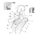
図1において、1は、シートバック2の側部に配設されたサイドエアバッグ装置であり、そのエアバッグ3が折り畳み状態でインフレータ4とともに筐体5(詳細構造は省略)内に配置されている。そして、側突時に側方からの衝撃を受けると、インフレータ4からガスが噴出し、エアバッグ3が前方に膨張展開して、仮想線で示すように乗員(図示例では、ダミー形状で表示している)Mの胸部Mc及び頭部Mhの側方を保護するように構成されている。
【0016】
上記エアバッグ3は、シート上に座った乗員Mの肩部Msないし腋下部の後部の基部6と基部6から乗員Mの頭部Mhの側部に向けて斜め前方上方に膨出する上方膨出部7と基部6から乗員Mの胸部Mcの側部に向けて斜め前方下方に膨出する下方膨出部8とを有する略ハート形状に構成されている。
【0017】
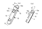
インフレータ4は、そのガス噴出部9が基部6における両膨出部7、8の膨出方向の交点位置近傍に配置されている。さらに、図2(a)、(b)に示すように、ガス噴出部9は両膨出部7、8の膨出方向に向けて2方向にガスを吹き出すようにその噴出口が設けられている。また、インフレータ4は、シートバック2の側面に沿って上下方向に配設された筒状保持ケース10内に配置固定されており、その筒状保持ケース10は複数の取付ねじ15にて筐体5に固定される。インフレータ4のガス噴出部9は筒状保持ケース10内の上端開口10aの近傍に配置され、筒状保持ケース10の周壁のガス噴出部9の下部位置に開口10bが形成されている。そして、ガス噴出部9の一方の噴出口から噴出したガスは主として上端開口10aから上方膨出部7に向けて流出し、他方の噴出口から噴出したガスは主として開口10bから下方膨出部8に向けて流出するように配置構成され、上端開口10aが上方膨出部7に向けてガスを流出する第1のガス噴出開口11を構成し、開口10bが下方膨出部8に向けてガスを流出する第2のガス噴出開口12を構成している。
【0018】
以上の構成において、側方からの衝撃によってインフレータ4が作動すると、その噴出ガスによってエアバッグ3は図1に仮想線で示すように基部6から上方膨出部7と下方膨出部8がそれぞれ斜め上方前方と斜め下方前方に膨出展開する。したがって、乗員Mの腕Maと干渉する恐れがなくかつ展開した上方膨出部7と下方膨出部8にてそれぞれ乗員Mの頭部Mhと胸部Mcが共に保護されるため、従来のように頭部Mhの保護時間が短くなることはなく、頭部Mhと胸部Mcを安定的に保護することができる。
【0019】
また、インフレータ4のガス噴出部9から筒状保持ケース10の第1のガス噴出開口11及び第2のガス噴出開口12を通して両膨出部7、8の膨出方向に向けて2方向にガスを吹き出すように構成されているので、噴出ガスによって両膨出部7、8がほぼ同時に確実に膨出展開され、上記作用効果が一層安定して得られる。
【0020】
次に、本発明のサイドエアバッグ装置の第2の実施形態について、図3を参照して説明する。
【0021】
本実施形態では、エアバッグ3の上方膨出部7と下方膨出部8との間のV字状の空間を基部6側に乗員Mの肩部Msより後方に入り込むように切り込んで、切り込み空間部13を形成している。
【0022】
このように構成すると、エアバッグ3を膨出展開させた時に、腕Maと干渉することをさらに確実に防止することができる。
【0023】
次に、本発明のサイドエアバッグ装置の第3の実施形態について、図4を参照して説明する。
【0024】
上記実施形態では、図4(a)に示すように、上方膨出部7をほぼ同じ幅で斜め上方前方に延出した例を示したが、本実施形態では、上方膨出部7の先端側に、斜め前方下方及び斜め後方上方に向けて突出する突出部14a、14bを形成して先端側に向けて幅の広くなる先太形状に形成している。
【0025】
このように構成すると、頭部Mhの保護領域を広くでき、頭部Mhが前後に移動しても確実に保護することができる。
【0026】
次に、本発明のサイドエアバッグ装置の第4の実施形態について、図5、図6を参照して説明する。
【0027】
エアバッグ3の一般的な折り畳み方法は、図5(a)に示すように、ジャバラ状に折り畳む方向と直交する方向に大きく突出する部分、上記実施形態では上方膨出部7の先端部を裏返しつつ内部に押し込むように入れ込み、その後先端側からシャバラ状に折り畳み、最後にその両側部を内側に折り込んでコンパクトな折り畳み状態を得ているが、その場合エアバッグ3の膨出展開時に、図6(a)に示すように、上方膨出部7が矢印Cの如く側方から立ち上がるように膨出展開することになり、膨出展開が円滑に行われず、完全に膨出するまでに時間がかかる恐れがある。
【0028】
そこで、本実施形態では、図5(b)に示すように、エアバッグ3の上方膨出部7のほぼ全体を、基部6及び下方膨出部8の内部に裏返しつつ押し込むように入れ込み、その後先端側からジャバラ状に折り畳み、最後にその両側を内側に折り込んでコンパクトな折り畳み状態にして筐体5内に収納している。
【0029】
このように構成すると、エアバッグ3の膨出展開時に、図6(b)に示すように、上方膨出部7が斜め前方上方に向けて真っ直ぐ突き出すように円滑に膨出展開し、乗員Mの頭部Mhの保護作用の一層の安定化を図ることができる。
【0030】
【発明の効果】
本発明のサイドエアバッグ装置によれば、以上のようにエアバッグをシート上に座った乗員の肩部ないし腋下部の後部の基部と基部から頭部の側部に向けて斜め前方上方にほぼ同じ幅で真っ直ぐに膨出する上方膨出部と基部から乗員の胸部の側部に向けて斜め前方下方に膨出する下方膨出部とを有する略ハート形状に構成し、インフレータを基部における両膨出部の膨出方向の交点位置近傍に配置したので、インフレータからの噴出ガスによってエアバッグは基部から上方膨出部と下方膨出部がそれぞれ斜め上方前方と斜め下方前方に膨出展開し、したがって腕と干渉する恐れがなくかつ展開した上方膨出部と下方膨出部にて頭部と胸部を共に安定的に保護することができ、さらにインフレータから両膨出部の膨出方向に向けて2方向にガスを吹き出し、両膨出部がほぼ同時に確実に膨出展開されるので、上記作用効果を一層安定して得ることができる。
【0032】
また、エアバッグの上方膨出部と下方膨出部との間に、乗員の肩部より後方に入り込む切り込み空間部を設けると、腕と干渉することをさらに確実に防止できる。
【0034】
また、エアバッグを、上方膨出部のほぼ全体をその他の部分の内部に裏返しつつ押し込むように入れ込んだ後、先端側からジャバラ折りして収納すると、エアバッグの膨出展開時に、上部膨出部が斜め前方上方に向けて突き出すように膨出展開して頭部の保護作用の一層の安定化を図ることができる。
【図面の簡単な説明】
【図1】本発明のサイドエアバッグ装置の第1の実施形態の側面図である。
【図2】同実施形態におけるインフレータを示し、(a)は斜視図、(b)は(a)のD−D矢視断面図である。
【図3】本発明のサイドエアバッグ装置の第2の実施形態の側面図である。
【図4】本発明のサイドエアバッグ装置の第3の実施形態の説明図で、(a)は比較として示した要部の側面図、(b)は本実施形態の要部の側面図である。
【図5】本発明のサイドエアバッグ装置の第4の実施形態の説明図で、(a)は比較として示した一般的なエアバッグの折り畳み工程の説明図、(b)は本実施形態のエアバッグの折り畳み工程の説明図である。
【図6】同実施形態の作用説明図で、(a)は比較として示した一般的なエアバッグの膨出工程の状態説明図、(b)は本実施形態のエアバッグの膨出工程の状態説明図である。
【図7】従来例におけるサイドエアバッグ装置の側面図である。
【符号の説明】
1 サイドエアバッグ装置
2 シートバック
3 エアバッグ
4 インフレータ
6 基部
7 上方膨出部
8 下方膨出部
13 切り込み空間部
14a、14b 突出部
M 乗員
Mh 頭部
Mc 胸部
Ma 腕
Ms 肩部[0001]
BACKGROUND OF THE INVENTION
The present invention relates to an airbag device that protects an occupant from an impact at the time of an automobile collision, and more particularly to a side airbag device that protects an occupant's chest and head against an impact from a side.
[0002]
[Prior art]
A conventional side airbag device that protects an occupant's chest and head against an impact from the side of a vehicle body is required in the airbag and the airbag as disclosed in, for example, Japanese Patent Laid-Open No. 9-188214. An inflator that blows out gas sometimes is housed in a housing. This side airbag device is disposed on one side of the seatback, that is, one side of the rear of an occupant sitting on the seat, and the airbag is inflated forward by the gas ejected from the inflator at the time of a side collision. It is comprised so that each side part of a door and a passenger | crew's chest and head may be protected.
[0003]
An example will be described with reference to FIG. 7. The
[0004]
[Problems to be solved by the invention]
However, in the case where the
[0005]
Further, since the distance from the gas outlet 24a of the
[0006]
In addition, the above publication discloses a head airbag and a chest airbag that are provided independently and each provided with an inflator, but there is no guarantee of the simultaneous operation of both inflators, and both airbags are not guaranteed. There is a problem with the protective action when the operation of the bag varies.
[0007]
In Japanese Patent Laid-Open Nos. 9-123864 and 9-220993, a head airbag and a chest airbag are provided completely or almost completely independently, and the gas ejected from a single inflator is both supplied. Although what was comprised so that it may inject toward an airbag is disclosed, since it is made to inject the ejection gas from an inflator mainly and ahead toward a chest airbag, head Mh There is a problem that the protection of the head Mh is not stable because the protection of the head Mh is delayed.
[0008]
In view of the above-described conventional problems, an object of the present invention is to provide a side airbag device that can stably protect both the head and the chest without interfering with the arm.
[0009]
[Means for Solving the Problems]
A side airbag device according to the present invention includes an airbag and an inflator that blows out gas into the airbag when necessary, and is disposed on a side portion of a seat back so that an occupant's chest and head are affected by a side impact. A side airbag device that protects the vehicle, and the airbag has a shoulder portion or a rear base portion of a passenger seated on a seat with a substantially same width obliquely forward and upward from the base portion to the side portion of the head portion. The inflator is configured in a substantially heart shape having an upper bulging portion that bulges straight and a lower bulging portion that bulges obliquely forward and downward from the base toward the side of the chest of the occupant. It is arranged near the intersection of the bulging direction of both bulging parts in the base and is configured to blow out gas in two directions toward the bulging direction of both bulging parts. It ’s like a side or When the inflator is actuated by the shock of the air bag, the air bag causes the upper bulging portion and the lower bulging portion to bulge and expand from the base to the diagonally upper front and the diagonally lower front, respectively, so that there is no risk of interference with the arm and Since both the head and chest are protected by the expanded upper and lower bulges, the protection time for the head is not shortened and the head and chest are protected stably. Further, gas is blown out in two directions from the inflator toward the bulging direction of the two bulging portions, and both the bulging portions are surely bulged and deployed almost simultaneously by the blown gas. Obtained stably.
[0011]
In addition, if a notch space portion is provided between the upper bulging portion and the lower bulging portion of the airbag so as to enter the rear from the shoulder portion of the occupant, interference with the arm can be more reliably prevented.
[0013]
If the airbag is inserted so that almost the entire upper bulging portion is pushed inside the other portion while being turned over, and then folded and stored from the tip side, the upper bulging portion is expanded when the airbag is bulged and deployed. Since the protruding portion does not bulge and expand so as to stand up from the side, it bulges and expands so as to protrude straight upward and obliquely upward, so that the head protecting action can be further stabilized.
[0014]
DETAILED DESCRIPTION OF THE INVENTION
Hereinafter, an embodiment of a side airbag device of the present invention will be described with reference to FIGS. 1 and 2.
[0015]
In FIG. 1,
[0016]
The
[0017]
In the
[0018]
In the above configuration, when the
[0019]
Further, gas flows in two directions from the
[0020]
Next, a second embodiment of the side airbag device of the present invention will be described with reference to FIG.
[0021]
In the present embodiment, the V-shaped space between the upper bulging
[0022]
If comprised in this way, when the
[0023]
Next, a third embodiment of the side airbag device of the present invention will be described with reference to FIG.
[0024]
In the above embodiment, as shown in FIG. 4A, an example in which the upper bulging
[0025]
If comprised in this way, the protection area | region of the head Mh can be enlarged, and even if the head Mh moves back and forth, it can protect reliably.
[0026]
Next, a fourth embodiment of the side airbag device of the present invention will be described with reference to FIGS.
[0027]
As shown in FIG. 5 (a), a general folding method of the
[0028]
Therefore, in the present embodiment, as shown in FIG. 5B, almost the entire upper bulging
[0029]
With this configuration, when the
[0030]
【The invention's effect】
According to the side airbag device of the present invention, as described above, the rear portion of the shoulder portion or the lower portion of the heel of the occupant sitting on the seat and the base portion of the rear portion from the base portion to the side portion of the head portion are substantially obliquely forward and upward. An inflator is formed in a substantially heart shape having an upper bulging portion that bulges straight with the same width and a lower bulging portion that bulges obliquely forward and downward from the base toward the side of the chest of the occupant. Since it is arranged near the intersection position of the bulging part in the bulging direction, the airbag bulges from the base part to the upper bulging part and the lower bulging part from the base to the diagonally upper front and the diagonally lower front, respectively. Therefore, there is no risk of interference with the arm, and the head and chest can be stably protected together with the expanded upper and lower bulges, and the bulges of both bulges from the inflator can be protected. Gas in two directions Balloon, since both bulging portions are substantially simultaneously reliably inflated to deploy, can be obtained by the above operation and effect more stable.
[0032]
In addition, if a notch space portion is provided between the upper bulging portion and the lower bulging portion of the airbag so as to enter the rear from the shoulder portion of the occupant, interference with the arm can be more reliably prevented.
[0034]
If the airbag is inserted so that almost the entire upper bulging portion is pushed inside the other portion while being turned over, and then folded and stored from the tip side, the upper bulging portion is expanded when the airbag is bulged and deployed. By further expanding and projecting so that the protruding portion protrudes obliquely upward and upward, the head protecting function can be further stabilized.
[Brief description of the drawings]
FIG. 1 is a side view of a first embodiment of a side airbag device of the present invention.
2A and 2B show an inflator according to the embodiment, wherein FIG. 2A is a perspective view, and FIG. 2B is a cross-sectional view taken along line DD in FIG.
FIG. 3 is a side view of a second embodiment of the side airbag device of the present invention.
4A and 4B are explanatory views of a third embodiment of the side airbag device of the present invention, in which FIG. 4A is a side view of a main part shown as a comparison, and FIG. 4B is a side view of the main part of the present embodiment. is there.
5A and 5B are explanatory views of a fourth embodiment of the side airbag device of the present invention. FIG. 5A is an explanatory view of a general airbag folding process shown as a comparison, and FIG. 5B is an explanatory view of the embodiment. It is explanatory drawing of the folding process of an airbag.
6A and 6B are operation explanatory views of the embodiment, in which FIG. 6A is a state explanatory view of a general airbag inflating process shown as a comparison, and FIG. 6B is an airbag inflating process of the present embodiment; It is a state explanatory view.
FIG. 7 is a side view of a side airbag device in a conventional example.
[Explanation of symbols]
DESCRIPTION OF
Claims (3)
Priority Applications (1)
| Application Number | Priority Date | Filing Date | Title |
|---|---|---|---|
| JP08373999A JP4037005B2 (en) | 1999-03-26 | 1999-03-26 | Side airbag device |
Applications Claiming Priority (1)
| Application Number | Priority Date | Filing Date | Title |
|---|---|---|---|
| JP08373999A JP4037005B2 (en) | 1999-03-26 | 1999-03-26 | Side airbag device |
Publications (2)
| Publication Number | Publication Date |
|---|---|
| JP2000272463A JP2000272463A (en) | 2000-10-03 |
| JP4037005B2 true JP4037005B2 (en) | 2008-01-23 |
Family
ID=13810902
Family Applications (1)
| Application Number | Title | Priority Date | Filing Date |
|---|---|---|---|
| JP08373999A Expired - Fee Related JP4037005B2 (en) | 1999-03-26 | 1999-03-26 | Side airbag device |
Country Status (1)
| Country | Link |
|---|---|
| JP (1) | JP4037005B2 (en) |
Families Citing this family (11)
| Publication number | Priority date | Publication date | Assignee | Title |
|---|---|---|---|---|
| JP2001171468A (en) * | 1999-12-13 | 2001-06-26 | Toyoda Gosei Co Ltd | Side air bag device |
| WO2004065179A1 (en) * | 2003-01-20 | 2004-08-05 | Toyota Jidosha Kabushiki Kaisha | Vehicle occupant protection device |
| JP2005047471A (en) * | 2003-07-31 | 2005-02-24 | Toyoda Gosei Co Ltd | Method for folding air bag and air bag device |
| JP2006088851A (en) * | 2004-09-22 | 2006-04-06 | Toyoda Gosei Co Ltd | Method of folding up airbag and airbag device |
| WO2006049101A1 (en) * | 2004-11-05 | 2006-05-11 | Autoliv Development Ab | Side air bag device and side air bag system |
| JP4808437B2 (en) * | 2005-05-18 | 2011-11-02 | 富士重工業株式会社 | Side airbag device and method for folding the airbag |
| JP4245031B2 (en) | 2006-09-28 | 2009-03-25 | トヨタ自動車株式会社 | Side airbag device for vehicle |
| JP5035004B2 (en) * | 2008-02-18 | 2012-09-26 | 豊田合成株式会社 | Side airbag device |
| DE102008063794B4 (en) | 2008-12-17 | 2014-04-03 | TAKATA Aktiengesellschaft | Airbag for a vehicle occupant restraint system |
| KR101260468B1 (en) * | 2011-03-03 | 2013-05-06 | 아우토리브 디벨롭먼트 아베 | Vehicles seat mounted side airbag apparatus |
| JP5885514B2 (en) * | 2012-01-18 | 2016-03-15 | オートリブ ディベロップメント エービー | Side airbag |
-
1999
- 1999-03-26 JP JP08373999A patent/JP4037005B2/en not_active Expired - Fee Related
Also Published As
| Publication number | Publication date |
|---|---|
| JP2000272463A (en) | 2000-10-03 |
Similar Documents
| Publication | Publication Date | Title |
|---|---|---|
| JP6263627B2 (en) | Airbag device | |
| JP6491739B2 (en) | Airbag device | |
| WO2016147683A1 (en) | Air bag device | |
| JP3520836B2 (en) | Head protection airbag device | |
| JP3365271B2 (en) | Airbag device for automobile side collision | |
| JP6265189B2 (en) | Side airbag device for rear seats | |
| KR101708217B1 (en) | Airbag apparatus for vehicle | |
| JP6281462B2 (en) | Vehicle seat with movable armrest with side airbag | |
| US11752965B2 (en) | Side airbag device and method for manufacturing side airbag device | |
| CN114174128B (en) | Airbag device | |
| JP2003285713A (en) | Side air bag device | |
| JP4037005B2 (en) | Side airbag device | |
| JP3982423B2 (en) | Airbag | |
| JP6450833B2 (en) | Airbag device | |
| JP4123048B2 (en) | Head protection airbag device | |
| JP2016153262A (en) | Air bag device | |
| JP2005041460A (en) | Air bag device for back seat and air bag system | |
| KR102543716B1 (en) | Side airbag apparatus for vehicle | |
| JPH07215160A (en) | Side air bag device | |
| JP2020050085A (en) | Side airbag device | |
| JP6559847B2 (en) | Airbag device | |
| JP7083909B2 (en) | Airbag device | |
| JP3532132B2 (en) | Side airbag device | |
| JP7059913B2 (en) | Airbag device | |
| KR101867061B1 (en) | Curtain airbag for vehicle |
Legal Events
| Date | Code | Title | Description |
|---|---|---|---|
| A977 | Report on retrieval |
Free format text: JAPANESE INTERMEDIATE CODE: A971007 Effective date: 20040629 |
|
| A131 | Notification of reasons for refusal |
Free format text: JAPANESE INTERMEDIATE CODE: A131 Effective date: 20040727 |
|
| A521 | Written amendment |
Free format text: JAPANESE INTERMEDIATE CODE: A523 Effective date: 20040902 |
|
| A02 | Decision of refusal |
Free format text: JAPANESE INTERMEDIATE CODE: A02 Effective date: 20050329 |
|
| A521 | Written amendment |
Free format text: JAPANESE INTERMEDIATE CODE: A523 Effective date: 20050516 |
|
| A521 | Written amendment |
Free format text: JAPANESE INTERMEDIATE CODE: A523 Effective date: 20050502 |
|
| A911 | Transfer of reconsideration by examiner before appeal (zenchi) |
Free format text: JAPANESE INTERMEDIATE CODE: A911 Effective date: 20050606 |
|
| A912 | Removal of reconsideration by examiner before appeal (zenchi) |
Free format text: JAPANESE INTERMEDIATE CODE: A912 Effective date: 20050708 |
|
| A521 | Written amendment |
Free format text: JAPANESE INTERMEDIATE CODE: A523 Effective date: 20070511 |
|
| A59 | Written plea |
Free format text: JAPANESE INTERMEDIATE CODE: A59 Effective date: 20070524 |
|
| A61 | First payment of annual fees (during grant procedure) |
Free format text: JAPANESE INTERMEDIATE CODE: A61 Effective date: 20071031 |
|
| R150 | Certificate of patent or registration of utility model |
Free format text: JAPANESE INTERMEDIATE CODE: R150 |
|
| FPAY | Renewal fee payment (event date is renewal date of database) |
Free format text: PAYMENT UNTIL: 20101109 Year of fee payment: 3 |
|
| FPAY | Renewal fee payment (event date is renewal date of database) |
Free format text: PAYMENT UNTIL: 20111109 Year of fee payment: 4 |
|
| FPAY | Renewal fee payment (event date is renewal date of database) |
Free format text: PAYMENT UNTIL: 20111109 Year of fee payment: 4 |
|
| FPAY | Renewal fee payment (event date is renewal date of database) |
Free format text: PAYMENT UNTIL: 20121109 Year of fee payment: 5 |
|
| FPAY | Renewal fee payment (event date is renewal date of database) |
Free format text: PAYMENT UNTIL: 20121109 Year of fee payment: 5 |
|
| FPAY | Renewal fee payment (event date is renewal date of database) |
Free format text: PAYMENT UNTIL: 20131109 Year of fee payment: 6 |
|
| LAPS | Cancellation because of no payment of annual fees |