JP4036616B2 - Solar cell module - Google Patents
Solar cell module Download PDFInfo
- Publication number
- JP4036616B2 JP4036616B2 JP2001007564A JP2001007564A JP4036616B2 JP 4036616 B2 JP4036616 B2 JP 4036616B2 JP 2001007564 A JP2001007564 A JP 2001007564A JP 2001007564 A JP2001007564 A JP 2001007564A JP 4036616 B2 JP4036616 B2 JP 4036616B2
- Authority
- JP
- Japan
- Prior art keywords
- solar cell
- film
- resin
- moisture
- resin film
- Prior art date
- Legal status (The legal status is an assumption and is not a legal conclusion. Google has not performed a legal analysis and makes no representation as to the accuracy of the status listed.)
- Expired - Fee Related
Links
Images


Classifications
-
- B—PERFORMING OPERATIONS; TRANSPORTING
- B32—LAYERED PRODUCTS
- B32B—LAYERED PRODUCTS, i.e. PRODUCTS BUILT-UP OF STRATA OF FLAT OR NON-FLAT, e.g. CELLULAR OR HONEYCOMB, FORM
- B32B17/00—Layered products essentially comprising sheet glass, or glass, slag, or like fibres
- B32B17/06—Layered products essentially comprising sheet glass, or glass, slag, or like fibres comprising glass as the main or only constituent of a layer, next to another layer of a specific material
- B32B17/10—Layered products essentially comprising sheet glass, or glass, slag, or like fibres comprising glass as the main or only constituent of a layer, next to another layer of a specific material of synthetic resin
- B32B17/10005—Layered products essentially comprising sheet glass, or glass, slag, or like fibres comprising glass as the main or only constituent of a layer, next to another layer of a specific material of synthetic resin laminated safety glass or glazing
- B32B17/1055—Layered products essentially comprising sheet glass, or glass, slag, or like fibres comprising glass as the main or only constituent of a layer, next to another layer of a specific material of synthetic resin laminated safety glass or glazing characterized by the resin layer, i.e. interlayer
- B32B17/10788—Layered products essentially comprising sheet glass, or glass, slag, or like fibres comprising glass as the main or only constituent of a layer, next to another layer of a specific material of synthetic resin laminated safety glass or glazing characterized by the resin layer, i.e. interlayer containing ethylene vinylacetate
-
- B—PERFORMING OPERATIONS; TRANSPORTING
- B32—LAYERED PRODUCTS
- B32B—LAYERED PRODUCTS, i.e. PRODUCTS BUILT-UP OF STRATA OF FLAT OR NON-FLAT, e.g. CELLULAR OR HONEYCOMB, FORM
- B32B17/00—Layered products essentially comprising sheet glass, or glass, slag, or like fibres
- B32B17/06—Layered products essentially comprising sheet glass, or glass, slag, or like fibres comprising glass as the main or only constituent of a layer, next to another layer of a specific material
- B32B17/10—Layered products essentially comprising sheet glass, or glass, slag, or like fibres comprising glass as the main or only constituent of a layer, next to another layer of a specific material of synthetic resin
- B32B17/10005—Layered products essentially comprising sheet glass, or glass, slag, or like fibres comprising glass as the main or only constituent of a layer, next to another layer of a specific material of synthetic resin laminated safety glass or glazing
- B32B17/10009—Layered products essentially comprising sheet glass, or glass, slag, or like fibres comprising glass as the main or only constituent of a layer, next to another layer of a specific material of synthetic resin laminated safety glass or glazing characterized by the number, the constitution or treatment of glass sheets
- B32B17/10018—Layered products essentially comprising sheet glass, or glass, slag, or like fibres comprising glass as the main or only constituent of a layer, next to another layer of a specific material of synthetic resin laminated safety glass or glazing characterized by the number, the constitution or treatment of glass sheets comprising only one glass sheet
-
- H—ELECTRICITY
- H10—SEMICONDUCTOR DEVICES; ELECTRIC SOLID-STATE DEVICES NOT OTHERWISE PROVIDED FOR
- H10F—INORGANIC SEMICONDUCTOR DEVICES SENSITIVE TO INFRARED RADIATION, LIGHT, ELECTROMAGNETIC RADIATION OF SHORTER WAVELENGTH OR CORPUSCULAR RADIATION
- H10F19/00—Integrated devices, or assemblies of multiple devices, comprising at least one photovoltaic cell covered by group H10F10/00, e.g. photovoltaic modules
- H10F19/80—Encapsulations or containers for integrated devices, or assemblies of multiple devices, having photovoltaic cells
-
- B—PERFORMING OPERATIONS; TRANSPORTING
- B32—LAYERED PRODUCTS
- B32B—LAYERED PRODUCTS, i.e. PRODUCTS BUILT-UP OF STRATA OF FLAT OR NON-FLAT, e.g. CELLULAR OR HONEYCOMB, FORM
- B32B2327/00—Polyvinylhalogenides
- B32B2327/12—Polyvinylhalogenides containing fluorine
-
- Y—GENERAL TAGGING OF NEW TECHNOLOGICAL DEVELOPMENTS; GENERAL TAGGING OF CROSS-SECTIONAL TECHNOLOGIES SPANNING OVER SEVERAL SECTIONS OF THE IPC; TECHNICAL SUBJECTS COVERED BY FORMER USPC CROSS-REFERENCE ART COLLECTIONS [XRACs] AND DIGESTS
- Y02—TECHNOLOGIES OR APPLICATIONS FOR MITIGATION OR ADAPTATION AGAINST CLIMATE CHANGE
- Y02E—REDUCTION OF GREENHOUSE GAS [GHG] EMISSIONS, RELATED TO ENERGY GENERATION, TRANSMISSION OR DISTRIBUTION
- Y02E10/00—Energy generation through renewable energy sources
- Y02E10/50—Photovoltaic [PV] energy
Landscapes
- Photovoltaic Devices (AREA)
Description
【0001】
【発明の属する技術分野】
この発明は、太陽電池モジュールに係り、特に、表面部材及び裏面部材が透光性を有することにより、表裏両面側からの光入射を可能とした両面入射型太陽電池モジュールに関するものである。
【0002】
【従来の技術】
光エネルギーを直接電気エネルギーに変換する太陽電池装置は、無尽蔵な太陽光をエネルギー源としているため、環境問題等から石油・石炭等の化石エネルギーに代わるエネルギー源として期待され、実用化が進められている。かかる太陽電池装置を実際のエネルギー源として用いるためには、通常複数個の太陽電池素子を電気的に直列、或いは並列に接続することによりその出力を高めた太陽電池モジュールが使用されている。
【0003】
従来の太陽電池モジュールは、片面発電のものとしては、図14に示すように、表面ガラス100と裏面部材101との間に複数個の太陽電池素子110…がEVA(エチレン・ビニル・アセテート)などの透光性且つ絶縁性を有する樹脂102で封止された構造になっている。
【0004】
太陽電池素子110は、単結晶シリコン、多結晶シリコンなどの半導体材料から構成され、各太陽電池素子110間は銅箔板などの金属薄板からなる接続部材111…で直列に接続されている。また、裏面部材101には裏面からの水分の浸入を防ぐためにプラスチックフィルムでアルミニウム(Al)箔などの金属箔をサンドイッチした積層フィルムが用いられている。
【0005】
上記した太陽電池モジュールは、表面ガラス100と裏面部材101の間に厚みが0.4〜0.8mm程度のEVA等の樹脂シートをそれぞれ介在させて太陽電池素子110…を挟み、減圧下で加熱することにより、一体化して形成されている。
【0006】
また、太陽電池素子の光の有効利用を図るべく、光入射側の電極のみならず裏面側の電極まで透明電極の構成にし、太陽電池素子の表裏両面から光を入射させるように構成した両面入射型タイプの太陽電池素子が提案されている。このような構造においては、裏面部材も透光性部材が用いられる。
【0007】
【発明が解決しようとする課題】
太陽電池モジュールは、一般に屋外で長期間使用されるため耐候性に優れている必要がある。上述した両面入射型タイプの構造においては、裏面部材も透光性部材が用いられる。この裏面部材として透光性の樹脂フィルムを用いた場合には、金属箔をプラスチックフィルムでサンドイッチした積層フィルムに比べ水分が侵入しやすくなるため、さらに水分侵入の対策の必要がある。また、かかる透光性の樹脂フィルムとして水分透過率の小さいフィルムを用いることも提案されているが、依然として改善の余地が残っていた。
【0008】
この発明は、上述した従来の問題点を解消するためになされたものにして、耐湿性を改善することにより信頼性の向上した太陽電池モジュールを提供することを目的とする。
【0009】
【課題を解決するための手段】
まず、この発明者らは上述した水分の侵入による発電性能の低下の原因を調べるために、図14に示す構造において、裏面部材101にアルミニウム(Al)箔をポリ弗化ビニル(PVF)フィルムでサンドイッチした積層フィルムを用いた太陽電池モジュールと、PVFフィルムだけを用いた太陽電池モジュールの2種類のモジュールを作成し、それぞれについて耐湿試験(JIS C8917)を行った。この試験は、85℃、湿度93%に保持された恒温漕中に1000時間入れた前後での太陽電池特性を調べるもので、出力値が95%以上であることが合格の基準として定められている。ここでは、恒温漕中に入れる時間を1000時間として試験を行った。その結果、得られた出力変化率は裏面部材に積層フィルムを用いた場合99.0%であり、膜厚50μmのPVFフィルムを用いた場合は、92.0%であった。
【0010】
そして、この2種類の太陽電池モジュールについて鋭意検討したところ、太陽電池素子を封止する樹脂1g中に存在するナトリウム量が、積層フィルムを用いた場合0.3μg/gであるのに対して、PVFフィルムを用いた場合は3μg/gであり、出力変化率と相関関係にあり、樹脂中のナトリウム量が多いほど発電性能が低下する傾向があることが分かった。
【0011】
かかるナトリウム量の増加はモジュール中に侵入した水分の存在によるものと考えられる。すなわち、裏面部材に積層フィルムを用いた場合は太陽電池モジュールの外周部から水分が侵入する。これに対して、裏面部材に樹脂フィルムを用いた場合には、太陽電池モジュールの外周部に加えて、樹脂フィルムを透過しても水分が侵入することになる。この結果、樹脂フィルムを裏面部材に用いた方がモジュール中に侵入する水分量が多くなる。
【0012】
そして、モジュール中に水分が侵入すると、表面ガラスから析出したナトリウムイオンが水分を含んだ樹脂内を移動して太陽電池素子表面まで達し、さらに太陽電池素子内部にまで拡散することにより太陽電池素子の発電性能を低下させることになる。このために、発電性能は裏面部材に樹脂フィルムを用いた方が積層フィルムを用いたものに比べて低下したものと推察される。
【0013】
従って、この発明の目的は、裏面部材に樹脂フィルムを用いた場合においても表面ガラスへの水分の到達量を減らし、表面ガラスから析出されるナトリウムが太陽電池素子表面に達することを抑制することにより、信頼性を向上せんとするものである。
【0014】
この発明の太陽電池モジュールは、上記のことを考慮してなされたものにして、少なくともナトリウムを含有するガラスからなる表面側光透過部材と、裏面樹脂フィルムと、前記表面側光透過部材と裏面樹脂フィルムとの間に封止樹脂で封止された複数個の太陽電池素子と、を備えた太陽電池モジュールであって、前記太陽電池素子と前記表面側光透過部材との間に、相隣接する前記太陽電池素子の間に存在する少なくとも間隙部を含む位置に配置される水分透過防止層を備え、前記水分透過防止層は、12.6g/m 2 ・day以下の水蒸気透過度を有する透明樹脂フィルムからなることを特徴とする。
【0016】
上記した構成によれば、裏面樹脂フィルムを通して浸入した水分が、水分透過防止層によりブロックされ、表面ガラスと太陽電池素子間の封止樹脂の水分含有量の増加を防ぐことができる。
【0025】
前記水分透過防止層は、前記封止樹脂中に太陽電池素子間を覆うように形成してもよい。
【0026】
上記した構成によれば、裏面樹脂フィルムを通して浸入した水分が、水分透過防止層と太陽電池素子とによりブロックされ、表面ガラスと太陽電池素子間の封止樹脂の水分含有量の増加を防ぐことができる。
【0031】
【発明の実施の形態】
以下、この発明の実施の形態につき図面を参照して説明する。
まず、この発明に用いられる太陽電池素子1の一例につき図1を参照して説明する。図1は、表裏両面から光を入射させるように構成した太陽電池素子の一例を示す模式的斜視図である。この太陽電池素子は、単結晶シリコン基板と非晶質シリコン層との間に実質的に真性の非晶質シリコンを挟み、その界面での欠陥を低減し、ヘテロ接合界面の特性を改善した構造(以下、HIT構造という)において、表裏両面から光を入射可能にした太陽電池素子である。
【0032】
図1に示すように、この太陽電池素子1は、n型単結晶シリコン基板10上に、真性の非晶質シリコン層11が形成され、その上にp型非晶質シリコン層12が形成されている。そして、p型非晶質シリコン層12の全面にITOなどからなる受光面側の透明電極13が設けられ、この受光面側透明電極13上に銀(Ag)等からなる櫛形集電極14が形成されている。また、基板10の裏面は基板裏面に内部電界を導入したいわゆるBSF(Back Surface Field)型構造になっている。すなわち、基板10の裏面側に真性非晶質シリコン層15を介してハイドープn型非晶質シリコン層16が設けられている。このハイドープn型非晶質シリコン層16の全面にITOなどからなる裏面側透明電極17が形成され、この上に銀(Ag)等からなる櫛形集電極18が形成されている。このように、裏面側も結晶シリコン基板とハイドープ非晶質シリコン層との間に真性の非晶質シリコン層を挟み、その界面での欠陥を低減し、ヘテロ接合界面の特性を改良したBSF構造になっている。
【0033】
上記した図1に示す太陽電池素子1が図示しない接続部材により複数個直列に接続される。そして、表面ガラス20と裏面樹脂フィルム5との間にEVA(エチレン・ビニル・アセテート)樹脂を用いて複数個の太陽電池素子1…が封止されて、太陽電池モジュールが形成される。
【0034】
この実施形態では、裏面樹脂フィルム5には透明樹脂フィルムとしてPVF(ポリ弗化ビニル)フィルム、PET(ポリエチレン・テレフタレート)フィルムなどの耐熱性フィルムが用いられている。
【0035】
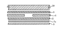
図2および図3に示す実施例1では、厚さ50μmのPETフィルムからなる裏面樹脂フィルム5の全面に水蒸気バリア性のあるSiOx等を蒸着して、水分透過防止層7aを形成したものを用いている。この構造において、裏面樹脂フィルム5側から浸入する水分をEVA樹脂よりも小さい水分透過率を有する水分透過防止層7aによりブロックするものである。
【0036】
尚、水分透過防止層7aとして、光を透過できる程度に薄い金属箔を用いる場合には、太陽電池素子1,1間が短絡しないように絶縁処理などを施している。
【0037】
表面ガラス20と太陽電池素子1…との間に0.6mm厚のEVA樹脂シート3を1枚介在させる。また、太陽電池素子1と裏面樹脂フィルム5の水分透過防止層7a側との間には0.6mm厚のEVA樹脂シート2を1枚介在させている。
【0038】
表面ガラス20上に、図2に示すように、各部材を重ね、100Pa程度に真空引きされた漕中に保持する。その後、全体を150℃程度に加熱し、裏面樹脂フィルム5側からシリコーンシートにて大気圧を用いて圧着する。このプロセスにてEVA2,3を軟化させ仮接着を行った後に、改めて150℃程度の恒温漕中にて1時間程度保持し、EVA2,3を架橋し、図3に示す太陽電池モジュールが形成される。
【0039】
図3に示す構造においては、裏面樹脂フィルム5を通して浸入した水分が、水分透過防止層7aによりブロックされ、表面ガラス20と太陽電池素子1…間のEVA樹脂3の水分含有量の増加を防ぐことができる。この結果、表面ガラス20から析出したナトリウムイオンの移動が抑制され、太陽電池素子の発電性能の低下を防止することができる。
【0040】
上記した水分透過防止層7aとしては、厚さ0.005〜0.1mmの薄板ガラスを用いることもできる。薄板ガラスを用いる場合にはPVFフィルムやPETフィルムからなる裏面樹脂フィルム5に接合し、裏面樹脂フィルム5とEVAシート2のとの間に、介在させれば良い。
【0041】
また、裏面樹脂フィルム5としては、PETフィルム以外に、PVF(ポリ弗化ビニル)、PVDF(ポリ弗化ビニリデン)、FEP(テトラフルオロエチレン−ヘキサフルオロポロピレン共重合体)、ETFE(エチレン−テトラフルオロエチレン共重合体)、PC(ポリカーボネート)、PVC(ポリ塩化ビニル)、PMMA(アクリル)、PETなどの耐熱性フィルムを用いることができる。この耐熱性フィルムに無機酸化物(アルミニウム酸化物、珪素酸化物)、窒化物(SiN)、弗化物(HgF,CaF)等を蒸着させて水分透過防止層7aを形成したものを用いることができる。無機酸化物等を蒸着すると、無機酸化物等に水蒸気バリア性があるため水分透過防止層として機能する。
【0042】
次に、この発明の実施例2につき図4及び図5に従い説明する。尚、実施例1と同じ部分には同じ符号を付し、説明の重複を避けるために、ここではその説明を省略する。
【0043】
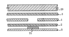
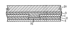
実施例1においては、水分透過防止層は裏面樹脂フィルム5の全面に設けたが、この実施例2においては、太陽電池素子1,1間の隙間を覆うように、厚さ50μmのPETフィルムからなる裏面樹脂シート5の一部に水分透過防止層7bを設けたものである。この水分透過防止層7bは、実施例1と同様に、水蒸気バリア性のあるSiOx等を蒸着して形成する。この水分透過防止層7bは、太陽電池素子1の端部を2mm程度覆うように太陽電池素子1,1間の間隔より大きくしている。
【0044】
そして、図4に示すように、水分透過防止層7bを設けた裏面樹脂フィルム5と太陽電池素子1…間にEVA樹脂シート2を介在させる。
【0045】
図4に示す実施例では、表面ガラス20と太陽電池素子1間のEVA樹脂を0.6mm厚のシート3を1枚用い、太陽電池素子1と水分透過防止層7bを設けた裏面樹脂フィルム5との間には0.6mm厚のEVAシート2を用いている。
【0046】
実施例1と同様に、表面ガラス20上に、図4に示すように、各部材を重ね、100Pa程度に真空引きされた漕中に保持する。その後、全体を150℃程度に加熱し、裏面樹脂フィルム5側からシリコーンシートにて大気圧を用いて圧着する。このプロセスにてEVA2、3を軟化させ仮接着を行った後に、改めて150℃程度の恒温漕中にて1時間程度保持し、EVA2、3を架橋し、図5に示す太陽電池モジュールが形成される。
【0047】
図5に示す構造においては、水分透過防止層7bと太陽電池素子1により水分の侵入がブロックされ、表面ガラス20と太陽電池素子1…間のEVA樹脂3の水分含有量の増加を防ぐことができる。
【0048】
次に、この発明の実施例3につき図6に従い説明する。尚、実施例1、2と同じ部分には同じ符号を付し、説明の重複を避けるために、ここではその説明を省略する。
【0049】
図6に示すように、表面ガラス20上に、各部材を重ね、100Pa程度に真空引きされた漕中に保持する。その後、全体を150℃程度に加熱し、裏面樹脂フィルム5側からシリコーンシートにて大気圧を用いて圧着する。このプロセスにてEVA2,3を軟化させ仮接着を行った後に、改めて150℃程度の恒温漕中にて1時間程度保持し、EVA2,3を架橋し、太陽電池モジュールが形成される。
【0050】
そして、この実施例3は、図6に示すように、厚さ50μmのPVFフィルムからなる裏面樹脂フィルム5の外側で且つ太陽電池素子1,1の隙間に相当する箇所に金属箔又はブチルゴムなどからなる水分透過防止層7cを設けている。水分透過防止層7cとして、アルミニウムなどの金属箔を用いる場合には、両面テープなどの接着剤を用いて裏面樹脂フィルム5に取り付ければよい。また、水分透過防止層7cとして、防湿性ブチルゴムを用いる場合には、該当部分にブチルゴムを塗りつければよい。
【0051】
図6に示す構造においては、水分透過防止層7cと太陽電池素子1により水分の侵入がブロックされ、表面ガラス20と太陽電池素子1…間のEVA樹脂3の水分含有量の増加を防ぐことができる。
【0052】
次に、この発明の実施例4につき図7および図8に従い説明する。尚、実施例1と同じ部分には同じ符号を付し、説明の重複を避けるために、ここではその説明を省略する。
【0053】
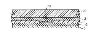
図7及び図8に示す実施例4では、太陽電池素子1,1間に金属箔又はブチルゴムなどからなる水分透過防止層7dが介在されている。尚、水分透過防止層7dとして金属箔を用いる場合には、太陽電池素子1,1間が短絡しないように絶縁処理などを施している。
【0054】
表面ガラス20と太陽電池素子1…との間に0.6mm厚のEVA樹脂シート3を1枚介在させる。また、太陽電池素子1と厚さ50μmのPVFフィルムからなる裏面樹脂フィルム5との間には0.6mm厚のEVA樹脂シート2を1枚介在させている。
【0055】
表面ガラス20上に、図7に示すように、各部材を重ね、100Pa程度に真空引きされた漕中に保持する。その後、全体を150℃程度に加熱し、裏面樹脂フィルム5側からシリコーンシートにて大気圧を用いて圧着する。このプロセスにてEVA2,3を軟化させ仮接着を行った後に、改めて150℃程度の恒温漕中にて1時間程度保持し、EVA2,3を架橋し、図8に示す太陽電池モジュールが形成される。
【0056】
図8に示す構造においては、裏面樹脂フィルム5を通して浸入した水分が、太陽電池素子1と水分透過防止層7dとによりブロックされ、表面ガラス20と太陽電池素子1…間のEVA樹脂3の水分含有量の増加を防ぐことができる。この結果、表面ガラス20から析出したナトリウムイオンの移動が抑制され、太陽電池素子の発電性能の低下を防止することができる。
【0057】
また、水分透過防止層7dとしてアルミニウムなどの金属箔を用いた場合、金属箔表面(表面ガラス20側)の反射率を高めると太陽電池素子1,1間に入射した光が金属箔面で反射し、EVA樹脂3を通り表面ガラス20面で再反射し、太陽電池素子1,1に入射する。その結果、太陽電池素子1,1の発電特性を高めることができる。
【0058】
次に、この発明の実施例5につき図9及び図10に従い説明する。尚、実施例1,4と同じ部分には同じ符号を付し、説明の重複を避けるために、ここではその説明を省略する。
【0059】
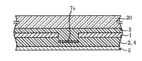
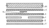
図9に示すように、厚さ50μmのPVFフィルムからなる裏面樹脂フィルム5と太陽電池素子1…間に2枚のEVA樹脂シート2,4を介在させる。そして、両樹脂シート2,4の間に太陽電池素子1,1間の隙間を覆うようにアルミニウムなどの金属箔からなる水分透過防止層7eを介在させる。この水分透過防止層7eは、太陽電池素子1の端部を2mm程度覆うように太陽電池素子1,1間の間隔より大きくしている。
【0060】
図10に示す実施例では、表面ガラス20と太陽電池素子1間のEVA樹脂を0.6mm厚のシート3を1枚用い、太陽電池素子1と裏面樹脂フィルム5との間には0.6mm厚のEVAシート2、4を2枚用いている。
【0061】
実施例4と同様に、表面ガラス20上に、図9に示すように、各部材を重ね、100Pa程度に真空引きされた漕中に保持する。その後、全体を150℃程度に加熱し、裏面樹脂フィルム5側からシリコーンシートにて大気圧を用いて圧着する。このプロセスにてEVA2,4,3を軟化させ仮接着を行った後に、改めて150℃程度の恒温漕中にて1時間程度保持し、EVA2,4,3を架橋し、図10に示す太陽電池モジュールが形成される。
【0062】
図10に示す構造においては、裏面樹脂フィルム5を通して浸入した水分が、水分透過防止層7eと太陽電池素子1とによりブロックされ、表面ガラス20と太陽電池素子1…間のEVA樹脂3の水分含有量の増加を防ぐことができる。この結果、表面ガラス20から析出したナトリウムイオンの移動が抑制され、太陽電池素子の発電性能の低下を防止することができる。
【0063】
次に、この発明の実施例6につき図11及び図12に従い説明する。尚、実施例1、4,5と同じ部分には同じ符号を付し、説明の重複を避けるために、ここではその説明を省略する。
【0064】
図11に示すように、表面ガラス20と太陽電池素子1…間の2枚のEVA樹脂シート3,4を介在させる。そして、両樹脂シートの3,4の間に太陽電池素子1,1間の隙間を覆うようにアルミニウムなどの金属箔からなる水分透過防止層7eを介在させる。この水分透過防止層7eは、太陽電池素子1の端部を2mm程度覆うように太陽電池素子1,1間の間隔より大きくしている。
【0065】
図11に示す実施例では、表面ガラス20と太陽電池素子1間に0.6mm厚のEVA樹脂シート3,4を2枚用い、太陽電池素子1と厚さ50μmのPVFフィルムからなる裏面樹脂フィルム5との間には0.6mm厚のEVAシート2を1枚用いている。
【0066】
実施例4、5と同様に、表面ガラス20上に、図11に示すように、各部材を重ね、100Pa程度に真空引きされた漕中に保持する。その後、全体を150℃程度に加熱し、裏面樹脂フィルム5側からシリコーンシートにて大気圧を用いて圧着する。このプロセスにてEVA2,4,3を軟化させ仮接着を行った後に、改めて150℃程度の恒温漕中にて1時間程度保持し、EVA2,4,3を架橋し、図12に示す太陽電池モジュールが形成される。
【0067】
図12に示す構造においては、裏面樹脂フィルム5を通して浸入した水分が、太陽電池素子1と水分透過防止層7eによりブロックされ、表面ガラス20と太陽電池素子1…間のEVA樹脂3の水分含有量の増加を防ぐことができる。この結果、表面ガラス20から析出したナトリウムイオンの移動が抑制され、太陽電池素子の発電性能の低下を防止することができる。
【0068】
また、図11に示す太陽電池モジュールにおいては、表面ガラス2と太陽電池素子1間の距離が実施例4のものより稼げることになり、例えば、0.6mmのEVAシート1枚のものに比べると2倍となり、その結果表面ガラス20から析出したナトリウムイオンが太陽電池素子1に到達するまでの時間を稼ぐことができる。従って、太陽電池の素子発電性能を低下させるまでの時間をのばし、ひいては、屋外におけるさらに長期な使用に耐えうる高い信頼性の太陽電池モジュールを供給することができる。
【0069】
次に、この発明の実施例7につき図13に従い説明する。尚、実施例1と同じ部分には同じ符号を付し、説明の重複を避けるために、ここではその説明を省略する。
【0070】
図13に示す実施の形態は、図3に示す実施例1のものに比べて、更に、表面ガラス20側のEVAシート3,4の間に封止樹脂よりも水蒸気透過度が小さい樹脂層である厚さ50μmのPETフィルム6を設けている。尚、図13において、図3と同一部分には同一符号を付している。
【0071】
この図13に示すように、表面ガラス20と太陽電池素子1との間に封止樹脂よりも水蒸気透過度が小さい樹脂層を介在させることで、表面ガラス20から析出したナトリウムイオンが太陽電池素子1…に到達することが抑制され、太陽電池素子1…の発電性能の低下をより防ぐことができる。
【0072】
次に、この発明による太陽電池モジュールと比較サンプルをそれぞれ形成し、耐湿試験(JIS C8917)を行った。この試験は85℃、湿度93%に保持された恒温漕中に1000時間入れた前後での太陽電池の特性を調べるもので、出力値は95%以上であることが合格の基準として定められている。
【0073】
1番のサンプルは、裏面材として、裏面からの水分の浸入を防ぐためにPVF(ポリ弗化ビニル)でアルミニウム(Al)箔をサンドイッチした積層フィルムを用いて、表面ガラス20との間にEVA樹脂を用いて太陽電池素子1…を樹脂封止したものである。2番のサンプルは、裏面材として、PVFフィルムを用いたものである。3番目のサンプルは、この発明の実施例1に示す構造のものである。4番目のサンプルは、この発明の実施例2に示す構造のものである。5番目のサンプルは、この発明の実施例3に示す構造のものである。6番目に示すサンプルは、この発明の実施例4に示す構造のものである。7番目のサンプルは、この発明の実施例5に示す構造のものである。8番目のサンプルは、この発明の実施例6に示す構造のものである。9番目のサンプルは、この発明の実施例7に示す構造のものである。各サンプルは、表に示した以外の条件は全て同じものであり、太陽電池素子1は両面入射タイプのHIT構造のものを用いた。
【0074】
上記各サンプルを上記に示す条件の恒温漕内に入れ同時に耐湿試験を施した。その結果を表1に示す。また、1000時間経過後の封止樹脂1g中に存在するナトリウム(Na)量を測定した結果を併せて示す。
【0075】
【表1】
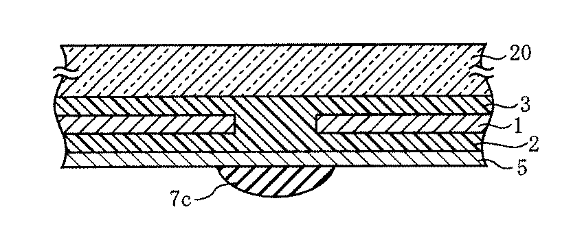
表1より、1000時間経過後において、裏面樹脂フィルムとして、透明樹脂フィルムを用いた本発明の太陽電池モジュールにおいても、裏面に積層フィルムを用いたものと遜色がないものが得られ、初期特性より95%以上の特性を満足しており、JISの規格はクリアしているものが得られる。
【0077】
尚、上記した実施の形態において、封止樹脂としてEVAを用いているが、シリコーン樹脂、ポリ塩化ビニル、PVB(ポリビニルブチラール)、ポリウレタンを用いることができる。
【0078】
次に、各材料の水蒸気透過度につき説明する。水蒸気透過度は、モコン法(JIS Z 0208−73で規定)で測定した。
【0079】
0.6mmの厚さのEVA樹脂は63g/m2・day、50μmの厚さのPETフィルムは12.6g/m2・day、50μmの厚さのPVFフィルムは15g/m2・dayである。
【0080】
また、水蒸気透過度は厚さに反比例し、例えば、厚さが2倍になると水蒸気透過度は半分になる。従って、EVA樹脂の厚さが1.0mmでは、水蒸気透過度は37.8g/m2・dayとなる。
【0081】
以上のことから、表面ガラス20と太陽電池素子1との間、裏面樹脂フィルムと太陽電池素子1との間の樹脂層の厚さを厚くしたり、裏面樹脂シートの厚さを厚くすることで、水分の透過を抑制できる。
【0082】
特に、両面入射型タイプでは、透過型の樹脂フィルムを用いる。透過型樹脂フィルムとして、PETフィルムとPVFフィルムを用いて各サンプルを作成し、耐湿性試験を行った。この試験は85℃、湿度93%に保持された恒温漕中に1000時間入れた前後での太陽電池の特性を調べるもので、出力値は95%以上であることが合格の基準として定められている。この結果を表2に示す。サンプルは、裏面部材5として、従来例としてサンプル番号1に裏面からの水分の浸入を防ぐために、PVFフィルムでAl箔をサンドイッチした積層フィルムを用い、裏面側のEVA樹脂2の厚みは0.6mmのものを用い且つ表面側のEVA樹脂の厚さが0.6mmのものを用いた。
【0083】
サンプル2は裏面部材5に厚み50μmのPVFフィルムを用い、且つ表面側のEVA樹脂の厚さが0.6mmのものを用いた以外は上記従来例と同じ構成のものを用意した。サンプル3は裏面部材5に厚み50μmのPETフィルムを用い、且つ表面側のEVA樹脂の厚さが0.6mmのものを用いた以外は従来例と同じ構成のものを用意した。サンプル4は裏面部材5に厚み100μmのPETフィルムを用い、且つ表面側のEVA樹脂の厚さが0.6mmのものを用いた以外は従来例と同じ構成のものを用意した。サンプル5は、裏面部材5に厚み100μmのPETフィルムを用い、表面側にそれぞれ0.6mm厚と0.4mm厚の2枚のEVAシート3,4を用いて表面側のEVA樹脂の厚みを1.0mmにしたものである。これら各サンプルは、サンプル1が表面ガラス20側からのみ光が入射する片面発電モジュールタイプであり、この他のサンプルは表裏両面から光が入射する両面入射型タイプである。これら各サンプルの初期特性からの劣化の度合いを測定した。また、1000時間経過後において、封止樹脂1g中に存在するナトリウム(Na)量を測定した結果も併せて示す。
【0084】
【表2】
表3より、裏面部材5に100μmのPETフィルムを用いたサンプル4の場合には、95%以上の特性が維持できるが、サンプル2及び3の場合には95%以上の特性を維持することができなかった。また、サンプル5に示すように、表面側のEVA樹脂の厚みを増やすと、サンプル3との比較より95%をクリアしているのがわかる。
【0086】
また、水蒸気透過度は100μmの厚さのPETフィルムは6.3g/m2・day、50μmの厚さPVFフィルムは15g/m2・dayである。
【0087】
表2より、両面入射型タイプの構造を用いる場合には、裏面側からの水蒸気の透過を極力避けることが必要である。この発明のように、水分透過防止層を設けることが表面ガラスからのナトリウムイオンの析出を抑制し、太陽電池素子の発電性能の低下を防ぐことができる。また、上記表2より、裏面樹脂フィルム5の膜厚を厚くし、水蒸気透過度を6.3g/m2・day以下にするとこの裏面樹脂フィルムが水分透過防止層の機能を果たすことになる。
【0088】
上記した実施例においては、太陽電池素子として、HIT構造の太陽電池素子を用いた場合につき説明したが、他の結晶系太陽電池素子、非晶質系太陽電池素子を用いた太陽電池モジュールにも本発明は適用することができる。
【0089】
【発明の効果】
以上説明したように、この発明によれば、表面ガラスからのナトリウムイオンの析出が抑制され、太陽電池素子の発電性能を低下させるまでの時間が延び、屋外におけるさらに長期な使用に耐えうる高い信頼性の太陽電池モジュールを提供することができる。
【図面の簡単な説明】
【図1】表裏から光を入射させるように構成した太陽電池素子の一例を示す模式的斜視図である。
【図2】この発明の実施例1に係る太陽電池モジュールの分解側面図である。
【図3】この発明の実施例1に係る太陽電池モジュールの側面図である。
【図4】この発明の実施例2に係る太陽電池モジュールの分解側面図である。
【図5】この発明の実施例2に係る太陽電池モジュールの側面図である。
【図6】この発明の実施例3に係る太陽電池モジュールの側面図である。
【図7】この発明の実施例4に係る太陽電池モジュールの分解側面図である。
【図8】この発明の実施例4に係る太陽電池モジュールの側面図である。
【図9】この発明の実施例5に係る太陽電池モジュールの分解側面図である。
【図10】この発明の実施例5に係る太陽電池モジュールの側面図である。
【図11】この発明の実施例6に係る太陽電池モジュールの分解側面図である。
【図12】この発明の実施例6に係る太陽電池モジュールの側面図である。
【図13】この発明の実施例7に係る太陽電池モジュールの側面図である。
【図14】従来の太陽電池モジュールの側面図である。
【符号の説明】
1 太陽電池素子
2、3,4 EVAシート
5 裏面樹脂フィルム
7a〜7e 水分透過防止層[0001]
BACKGROUND OF THE INVENTION
The present invention relates to a solar cell module, and more particularly to a double-sided solar cell module that allows light to be incident from both front and back sides by having a translucent surface member and back member.
[0002]
[Prior art]
Solar cell devices that directly convert light energy into electrical energy use inexhaustible sunlight as an energy source, and are expected to be an alternative energy source to fossil energy such as oil and coal due to environmental issues, and are being put to practical use. Yes. In order to use such a solar cell device as an actual energy source, a solar cell module whose output is increased by connecting a plurality of solar cell elements electrically in series or in parallel is generally used.
[0003]
As shown in FIG. 14, the conventional solar cell module has a plurality of
[0004]
The
[0005]
The solar cell module described above is sandwiched between the
[0006]
In addition, in order to make effective use of the light of the solar cell element, the double-sided incident is configured so that light is incident from both the front and back sides of the solar cell element, so that not only the light incident side electrode but also the back side electrode is configured as a transparent electrode. A type solar cell element has been proposed. In such a structure, a translucent member is used for the back member.
[0007]
[Problems to be solved by the invention]
Since a solar cell module is generally used outdoors for a long time, it needs to have excellent weather resistance. In the double-sided incident type structure described above, a translucent member is used as the back surface member. When a translucent resin film is used as the back member, moisture easily enters compared to a laminated film in which a metal foil is sandwiched with a plastic film, and therefore further countermeasures against moisture penetration are required. In addition, it has been proposed to use a film having a low water permeability as the translucent resin film, but there is still room for improvement.
[0008]
The present invention has been made to solve the above-described conventional problems, and an object thereof is to provide a solar cell module with improved reliability by improving moisture resistance.
[0009]
[Means for Solving the Problems]
First, in order to investigate the cause of the decrease in power generation performance due to the intrusion of moisture described above, the present inventors used an aluminum (Al) foil as a
[0010]
And when intensively examining these two types of solar cell modules, the amount of sodium present in 1 g of the resin sealing the solar cell element is 0.3 μg / g when using a laminated film, When the PVF film was used, it was 3 μg / g, which was correlated with the output change rate, and it was found that the power generation performance tends to decrease as the amount of sodium in the resin increases.
[0011]
This increase in the amount of sodium is thought to be due to the presence of moisture that has entered the module. That is, when a laminated film is used for the back member, moisture enters from the outer periphery of the solar cell module. On the other hand, when a resin film is used for the back member, moisture penetrates through the resin film in addition to the outer periphery of the solar cell module. As a result, the amount of moisture entering the module increases when the resin film is used as the back member.
[0012]
When moisture enters the module, sodium ions precipitated from the surface glass move through the resin containing moisture to reach the surface of the solar cell element, and further diffuse into the solar cell element. Power generation performance will be reduced. For this reason, it is surmised that the power generation performance is lower when the resin film is used for the back member than when the laminated film is used.
[0013]
Therefore, the object of the present invention is to reduce the amount of moisture reaching the surface glass even when a resin film is used for the back member, and to suppress the sodium precipitated from the surface glass from reaching the surface of the solar cell element. To improve reliability.
[0014]
The solar cell module of the present invention is made in consideration of the above, and contains at least sodium.Made of glassA plurality of solar cell elements sealed with a sealing resin between the front surface side light transmissive member, the back surface resin film, and the front surface side light transmissive member and the back surface resin film;A solar cell module comprising the solar cell element and the surface side light transmitting member,Moisture permeation preventive layer disposed at a position including at least a gap existing between adjacent solar cell elementsThe moisture permeation preventive layer is 12.6 g / m 2 -It consists of a transparent resin film having a water vapor permeability of not more than day.It is characterized by.
[0016]
According to the configuration described above, moisture that has entered through the back resin film is blocked by the moisture permeation preventive layer, and an increase in the moisture content of the sealing resin between the front glass and the solar cell element can be prevented.
[0025]
The moisture permeation preventing layer may be formed in the sealing resin so as to cover between the solar cell elements.
[0026]
According to the configuration described above, moisture that has entered through the back surface resin film is blocked by the moisture permeation preventive layer and the solar cell element, thereby preventing an increase in the moisture content of the sealing resin between the surface glass and the solar cell element. it can.
[0031]
DETAILED DESCRIPTION OF THE INVENTION
Embodiments of the present invention will be described below with reference to the drawings.
First, an example of the
[0032]
As shown in FIG. 1, in this
[0033]
A plurality of the
[0034]
In this embodiment, a heat resistant film such as a PVF (polyvinyl fluoride) film or a PET (polyethylene terephthalate) film is used for the
[0035]
In Example 1 shown in FIG. 2 and FIG. 3, use is made by forming a moisture permeation
[0036]
In addition, when using a metal foil thin enough to transmit light as the moisture permeation
[0037]
One
[0038]
As shown in FIG. 2, each member is stacked on the
[0039]
In the structure shown in FIG. 3, moisture that has entered through the
[0040]
As the moisture
[0041]
In addition to the PET film, the back
[0042]
Next, a second embodiment of the present invention will be described with reference to FIGS. In addition, the same code | symbol is attached | subjected to the same part as Example 1, and the description is abbreviate | omitted here in order to avoid duplication of description.
[0043]
In Example 1, the moisture permeation prevention layer was provided on the entire surface of the back
[0044]
And as shown in FIG. 4, the
[0045]
In the example shown in FIG. 4, the
[0046]
Similar to Example 1, as shown in FIG. 4, each member is stacked on the
[0047]
In the structure shown in FIG. 5, moisture penetration is blocked by the moisture permeation
[0048]
Next, a third embodiment of the present invention will be described with reference to FIG. In addition, the same code | symbol is attached | subjected to the same part as Example 1, 2, and the description is abbreviate | omitted here in order to avoid duplication of description.
[0049]
As shown in FIG. 6, each member is stacked on the
[0050]
And, as shown in FIG. 6, this Example 3 is made of a metal foil or butyl rubber on the outside of the back
[0051]
In the structure shown in FIG. 6, moisture penetration is blocked by the moisture permeation
[0052]
Next, a fourth embodiment of the present invention will be described with reference to FIGS. In addition, the same code | symbol is attached | subjected to the same part as Example 1, and the description is abbreviate | omitted here in order to avoid duplication of description.
[0053]
In Example 4 shown in FIGS. 7 and 8, a moisture permeation
[0054]
One
[0055]
As shown in FIG. 7, each member is stacked on the
[0056]
In the structure shown in FIG. 8, the moisture that has entered through the
[0057]
Further, when a metal foil such as aluminum is used as the moisture
[0058]
Next, a fifth embodiment of the present invention will be described with reference to FIGS. In addition, the same code | symbol is attached | subjected to the same part as Example 1, 4, and the description is abbreviate | omitted here in order to avoid duplication of description.
[0059]
As shown in FIG. 9, two
[0060]
In the example shown in FIG. 10, one sheet of 0.6 mm thick EVA resin between the
[0061]
As in Example 4, each member is stacked on the
[0062]
In the structure shown in FIG. 10, moisture that has entered through the
[0063]
Next, a sixth embodiment of the present invention will be described with reference to FIGS. In addition, the same code | symbol is attached | subjected to the same part as Example 1, 4, 5, and the description is abbreviate | omitted here in order to avoid duplication of description.
[0064]
As shown in FIG. 11, two
[0065]
In the embodiment shown in FIG. 11, two 0.6 mm thick
[0066]
As in Examples 4 and 5, as shown in FIG. 11, each member is stacked on the
[0067]
In the structure shown in FIG. 12, the moisture that has entered through the
[0068]
Moreover, in the solar cell module shown in FIG. 11, the distance between the
[0069]
Next, a seventh embodiment of the present invention will be described with reference to FIG. In addition, the same code | symbol is attached | subjected to the same part as Example 1, and the description is abbreviate | omitted here in order to avoid duplication of description.
[0070]
The embodiment shown in FIG. 13 is a resin layer having a water vapor permeability smaller than that of the sealing resin between the
[0071]
As shown in FIG. 13, a sodium ion deposited from the
[0072]
Next, a solar cell module according to the present invention and a comparative sample were formed, respectively, and a moisture resistance test (JIS C8917) was performed. This test examines the characteristics of the solar cell before and after 1000 hours in a constant temperature bath maintained at 85 ° C. and 93% humidity, and the output value is determined to be 95% or more as a criterion for acceptance. Yes.
[0073]
The first sample is an EVA resin between the
[0074]
Each of the above samples was placed in a constant temperature bath under the conditions described above and simultaneously subjected to a moisture resistance test. The results are shown in Table 1. Moreover, the result of having measured the amount of sodium (Na) present in 1 g of the sealing resin after 1000 hours is also shown.
[0075]
[Table 1]
From Table 1, after 1000 hours, the solar cell module of the present invention using a transparent resin film as the back resin film can be obtained which is not inferior to that using the laminated film on the back surface. Satisfies 95% or more of the characteristics, and a product satisfying the JIS standard can be obtained.
[0077]
In the embodiment described above, EVA is used as the sealing resin, but silicone resin, polyvinyl chloride, PVB (polyvinyl butyral), and polyurethane can be used.
[0078]
Next, the water vapor permeability of each material will be described. The water vapor transmission rate was measured by the Mokon method (specified by JIS Z 0208-73).
[0079]
0.6mm thick EVA resin is 63g / m2Day, PET film with a thickness of 50 μm is 12.6 g / m2-Day, PVF film with a thickness of 50 μm is 15 g / m2-Day.
[0080]
Further, the water vapor permeability is inversely proportional to the thickness. For example, when the thickness is doubled, the water vapor permeability is halved. Therefore, when the thickness of the EVA resin is 1.0 mm, the water vapor permeability is 37.8 g / m.2-It becomes day.
[0081]
From the above, by increasing the thickness of the resin layer between the
[0082]
In particular, in the double-sided incident type, a transmissive resin film is used. Each sample was prepared using a PET film and a PVF film as a transmissive resin film, and a moisture resistance test was performed. This test examines the characteristics of the solar cell before and after 1000 hours in a constant temperature bath maintained at 85 ° C. and 93% humidity, and the output value is determined to be 95% or more as a criterion for acceptance. Yes. The results are shown in Table 2. In order to prevent moisture from entering from the back surface of Sample No. 1 as a conventional example, the sample is a laminated film obtained by sandwiching an Al foil with a PVF film, and the thickness of the
[0083]
[0084]
[Table 2]
From Table 3, in the case of
[0086]
The water vapor permeability is 6.3 g / m for a PET film having a thickness of 100 μm.2-Day, 50 μm thick PVF film is 15 g / m2-Day.
[0087]
From Table 2, when using a double-sided incident type structure, it is necessary to avoid the transmission of water vapor from the back side as much as possible. As in the present invention, the provision of the moisture permeation preventive layer can suppress the precipitation of sodium ions from the surface glass and prevent the power generation performance of the solar cell element from being lowered. Moreover, from the said Table 2, the film thickness of the back
[0088]
In the above-described embodiments, the case where the solar cell element having the HIT structure is used as the solar cell element has been described. However, the solar cell module using other crystalline solar cell elements and amorphous solar cell elements is also used. The present invention is applicable.
[0089]
【The invention's effect】
As described above, according to the present invention, the precipitation of sodium ions from the surface glass is suppressed, the time until the power generation performance of the solar cell element is reduced is extended, and high reliability that can withstand long-term use outdoors. A solar cell module can be provided.
[Brief description of the drawings]
FIG. 1 is a schematic perspective view showing an example of a solar cell element configured to allow light to enter from the front and back sides.
FIG. 2 is an exploded side view of the solar cell module according to
FIG. 3 is a side view of the solar cell module according to
FIG. 4 is an exploded side view of a solar cell module according to
FIG. 5 is a side view of a solar cell module according to
FIG. 6 is a side view of a solar cell module according to
FIG. 7 is an exploded side view of a solar cell module according to
FIG. 8 is a side view of a solar cell module according to
FIG. 9 is an exploded side view of a solar cell module according to
FIG. 10 is a side view of a solar cell module according to
FIG. 11 is an exploded side view of a solar cell module according to
FIG. 12 is a side view of a solar cell module according to
FIG. 13 is a side view of a solar cell module according to Embodiment 7 of the present invention.
FIG. 14 is a side view of a conventional solar cell module.
[Explanation of symbols]
1 Solar cell element
2,3,4 EVA sheet
5 Back side resin film
7a-7e Moisture permeation prevention layer
Claims (2)
前記太陽電池素子と前記表面側光透過部材との間に、相隣接する前記太陽電池素子の間に存在する少なくとも間隙部を含む位置に配置される水分透過防止層を備え、
前記水分透過防止層は、12.6g/m 2 ・day以下の水蒸気透過度を有する透明樹脂フィルムからなることを特徴とする太陽電池モジュール。The surface-side light transmitting member made of glass containing at least sodium, and the back resin film, a plurality of solar cell elements sealed with a sealing resin between the surface-side light-transmitting member and the back surface resin film A solar cell module comprising
A moisture permeation preventive layer disposed between the solar cell element and the surface side light transmitting member and disposed at a position including at least a gap existing between the solar cell elements adjacent to each other ;
The moisture permeation preventive layer is formed of a transparent resin film having a water vapor permeability of 12.6 g / m 2 · day or less .
Priority Applications (2)
| Application Number | Priority Date | Filing Date | Title |
|---|---|---|---|
| JP2001007564A JP4036616B2 (en) | 2000-01-31 | 2001-01-16 | Solar cell module |
| US09/772,994 US6818819B2 (en) | 2000-01-31 | 2001-01-31 | Solar cell module |
Applications Claiming Priority (5)
| Application Number | Priority Date | Filing Date | Title |
|---|---|---|---|
| JP2000-22092 | 2000-01-31 | ||
| JP2000022094 | 2000-01-31 | ||
| JP2000-22094 | 2000-01-31 | ||
| JP2000022092 | 2000-01-31 | ||
| JP2001007564A JP4036616B2 (en) | 2000-01-31 | 2001-01-16 | Solar cell module |
Publications (2)
| Publication Number | Publication Date |
|---|---|
| JP2001291880A JP2001291880A (en) | 2001-10-19 |
| JP4036616B2 true JP4036616B2 (en) | 2008-01-23 |
Family
ID=27342189
Family Applications (1)
| Application Number | Title | Priority Date | Filing Date |
|---|---|---|---|
| JP2001007564A Expired - Fee Related JP4036616B2 (en) | 2000-01-31 | 2001-01-16 | Solar cell module |
Country Status (2)
| Country | Link |
|---|---|
| US (1) | US6818819B2 (en) |
| JP (1) | JP4036616B2 (en) |
Families Citing this family (63)
| Publication number | Priority date | Publication date | Assignee | Title |
|---|---|---|---|---|
| JP2001148500A (en) * | 1999-11-22 | 2001-05-29 | Sanyo Electric Co Ltd | Solar cell module |
| JP2001291881A (en) * | 2000-01-31 | 2001-10-19 | Sanyo Electric Co Ltd | Solar cell module |
| JP3557148B2 (en) * | 2000-02-21 | 2004-08-25 | 三洋電機株式会社 | Solar cell module |
| JP3889644B2 (en) * | 2002-03-25 | 2007-03-07 | 三洋電機株式会社 | Solar cell module |
| EP1560272B1 (en) * | 2004-01-29 | 2016-04-27 | Panasonic Intellectual Property Management Co., Ltd. | Solar cell module |
| US20050178428A1 (en) * | 2004-02-17 | 2005-08-18 | Solar Roofing Systems Inc. | Photovoltaic system and method of making same |
| JP5010468B2 (en) * | 2005-03-24 | 2012-08-29 | 京セラ株式会社 | Photoelectric conversion element, method for producing the same, and photoelectric conversion module using the same |
| JP2007067203A (en) * | 2005-08-31 | 2007-03-15 | Sanyo Electric Co Ltd | Solar cell module and method for manufacturing solar cell module |
| EP1997126A2 (en) * | 2006-03-13 | 2008-12-03 | Nanogram Corporation | Thin silicon or germanium sheets and photovoltaics formed from thin sheets |
| US8158450B1 (en) | 2006-05-05 | 2012-04-17 | Nanosolar, Inc. | Barrier films and high throughput manufacturing processes for photovoltaic devices |
| US20070295389A1 (en) * | 2006-05-05 | 2007-12-27 | Nanosolar, Inc. | Individually encapsulated solar cells and solar cell strings having a hybrid organic/inorganic protective layer |
| US8039739B1 (en) * | 2006-05-05 | 2011-10-18 | Nanosolar, Inc. | Individually encapsulated solar cells and solar cell strings |
| US20100297798A1 (en) * | 2006-07-27 | 2010-11-25 | Adriani Paul M | Individually Encapsulated Solar Cells and/or Solar Cell Strings |
| JP2008085293A (en) * | 2006-08-30 | 2008-04-10 | Keiwa Inc | Back sheet for solar cell module and solar cell module using the same |
| US20080053516A1 (en) | 2006-08-30 | 2008-03-06 | Richard Allen Hayes | Solar cell modules comprising poly(allyl amine) and poly (vinyl amine)-primed polyester films |
| US20080115825A1 (en) * | 2006-09-20 | 2008-05-22 | Patel Rajen M | Electronic Device Module Comprising an Ethylene Multi-Block Copolymer |
| US20080128018A1 (en) | 2006-12-04 | 2008-06-05 | Richard Allen Hayes | Solar cells which include the use of certain poly(vinyl butyral)/film bilayer encapsulant layers with a low blocking tendency and a simplified process to produce thereof |
| FR2910711B1 (en) * | 2006-12-20 | 2018-06-29 | Centre Nat Rech Scient | HETEROJUNCTION WITH INTRINSEALLY AMORPHOUS INTERFACE |
| US8197928B2 (en) | 2006-12-29 | 2012-06-12 | E. I. Du Pont De Nemours And Company | Intrusion resistant safety glazings and solar cell modules |
| JP5526461B2 (en) * | 2007-03-19 | 2014-06-18 | 三洋電機株式会社 | Photovoltaic device |
| WO2008136095A1 (en) * | 2007-04-24 | 2008-11-13 | Mitsubishi Electric Corporation | Solar battery module |
| TWI405340B (en) * | 2007-08-31 | 2013-08-11 | Nexpower Technology Corp | Thin film solar cell and manufacturing method thereof |
| US7810286B2 (en) * | 2007-11-01 | 2010-10-12 | Patrina Eiffert | Photovoltaic membrane system |
| US20110067327A1 (en) * | 2007-11-01 | 2011-03-24 | Patrina Eiffert | Isolation mount and photovoltaic module and roofing system incorporating the same |
| EP2234177A4 (en) * | 2007-12-10 | 2012-12-26 | Toyota Motor Co Ltd | SOLAR CELL MODULE |
| TWI440198B (en) * | 2008-03-13 | 2014-06-01 | Nexpower Technology Corp | Thin film laminated solar cell and manufacturing method thereof |
| CA2716191A1 (en) * | 2008-03-26 | 2009-10-01 | E. I. Du Pont De Nemours And Company | High performance anti-spall laminate article |
| US20090320896A1 (en) * | 2008-06-25 | 2009-12-31 | Gerhardinger Peter F | Moisture resistant solar panel and method of making same |
| US7641965B1 (en) | 2008-06-30 | 2010-01-05 | E.I. Du Pont De Nemours And Company | Transparent light-weight safety glazings |
| JP5436805B2 (en) * | 2008-07-04 | 2014-03-05 | 三洋電機株式会社 | Solar cell module |
| US20100101561A1 (en) * | 2008-10-24 | 2010-04-29 | Christopher Frank | Solar panels systems and methods |
| US20100294341A1 (en) * | 2008-10-24 | 2010-11-25 | Christopher Frank | Apparatus and methods for frameless building integrated photovoltaic panel |
| WO2010051522A1 (en) | 2008-10-31 | 2010-05-06 | E. I. Du Pont De Nemours And Company | Solar cells modules comprising low haze encapsulants |
| US20100154867A1 (en) | 2008-12-19 | 2010-06-24 | E. I. Du Pont De Nemours And Company | Mechanically reliable solar cell modules |
| JP5984241B2 (en) * | 2008-12-31 | 2016-09-06 | イー・アイ・デュポン・ドウ・ヌムール・アンド・カンパニーE.I.Du Pont De Nemours And Company | Solar cell module including an encapsulant sheet having low haze and high moisture resistance |
| DE102009000450A1 (en) * | 2009-01-28 | 2010-07-29 | Evonik Degussa Gmbh | Transparent, weather-resistant barrier film, production by lamination, extrusion lamination or extrusion coating |
| JP5306112B2 (en) * | 2009-02-17 | 2013-10-02 | 三洋電機株式会社 | Solar cell and solar cell module |
| DE102009003225A1 (en) * | 2009-05-19 | 2010-11-25 | Evonik Degussa Gmbh | Transparent, weather-resistant barrier film, production by lamination, extrusion lamination or extrusion coating |
| CN102859863A (en) * | 2009-07-31 | 2013-01-02 | 纳幕尔杜邦公司 | Cross-linkable encapsulants for photovoltaic cells |
| US8188363B2 (en) * | 2009-08-07 | 2012-05-29 | Sunpower Corporation | Module level solutions to solar cell polarization |
| WO2011034143A1 (en) * | 2009-09-17 | 2011-03-24 | 三洋電機株式会社 | Transparent conductive film and device comprising same |
| US8211265B2 (en) | 2010-06-07 | 2012-07-03 | E. I. Du Pont De Nemours And Company | Method for preparing multilayer structures containing a perfluorinated copolymer resin layer |
| US8211264B2 (en) | 2010-06-07 | 2012-07-03 | E I Du Pont De Nemours And Company | Method for preparing transparent multilayer film structures having a perfluorinated copolymer resin layer |
| US8609980B2 (en) | 2010-07-30 | 2013-12-17 | E I Du Pont De Nemours And Company | Cross-linkable ionomeric encapsulants for photovoltaic cells |
| US8409379B2 (en) | 2010-07-30 | 2013-04-02 | E I Du Pont De Nemours And Company | Multilayer structures containing a fluorinated copolymer resin layer and an ethylene terpolymer layer |
| JP2013537494A (en) | 2010-07-30 | 2013-10-03 | イー・アイ・デュポン・ドウ・ヌムール・アンド・カンパニー | Multilayer film comprising a fluorinated copolymer resin layer and a sealing layer |
| DE112011102882T5 (en) * | 2010-08-31 | 2013-06-06 | Global Solar Energy, Inc. | Flexible building-integrated photovoltaic structure |
| KR101616131B1 (en) * | 2010-10-05 | 2016-04-27 | 엘지전자 주식회사 | Solar cell module |
| US20120312366A1 (en) | 2010-12-22 | 2012-12-13 | E. I. Du Pont De Nemours And Company | Fire resistant back-sheet for photovoltaic module |
| US9050784B2 (en) | 2010-12-22 | 2015-06-09 | E I Du Pont De Nemours And Company | Fire resistant back-sheet for photovoltaic module |
| CN102954915A (en) * | 2011-08-21 | 2013-03-06 | 上海汉测试验设备有限公司 | Experiment table for mechanical loading of solar cell module |
| WO2013145975A1 (en) * | 2012-03-30 | 2013-10-03 | 株式会社フジクラ | Dye-sensitized solar battery |
| CN104584257B (en) | 2012-05-02 | 2017-06-20 | 汉高知识产权控股有限责任公司 | Curable encapsulants and uses thereof |
| JP5950154B2 (en) * | 2012-05-09 | 2016-07-13 | パナソニックIpマネジメント株式会社 | Solar cell module |
| WO2014100313A1 (en) | 2012-12-19 | 2014-06-26 | E.I. Du Pont De Nemours And Company | Cross-linked polymers and their use in packaging films and injection molded articles |
| US20140196773A1 (en) * | 2013-01-11 | 2014-07-17 | International Business Machines Corporation | Multi-junction iii-v solar cell |
| US9978895B2 (en) * | 2013-10-31 | 2018-05-22 | National Technology & Engineering Solutions Of Sandia, Llc | Flexible packaging for microelectronic devices |
| CN106232725A (en) | 2014-04-29 | 2016-12-14 | 纳幕尔杜邦公司 | There is the photovoltaic cell of the backboard of improvement |
| WO2015168068A1 (en) | 2014-04-29 | 2015-11-05 | E. I. Du Pont De Nemours And Company | Photovoltaic cells with improved multilayer backsheet |
| WO2015168073A1 (en) | 2014-04-29 | 2015-11-05 | E. I. Du Pont De Nemours And Company | Solar cell modules with improved backsheet |
| EP3157066A4 (en) * | 2014-06-13 | 2017-06-21 | Panasonic Intellectual Property Management Co., Ltd. | Solar cell module |
| TWI679259B (en) | 2014-08-11 | 2019-12-11 | 德商漢高智慧財產控股公司 | Optically clear hot melt adhesives and uses thereof |
| CN112447870A (en) * | 2019-08-16 | 2021-03-05 | 福建金石能源有限公司 | High-waterproof packaging material for solar cell |
Family Cites Families (15)
| Publication number | Priority date | Publication date | Assignee | Title |
|---|---|---|---|---|
| EP0018924B2 (en) * | 1979-05-08 | 1989-01-04 | Saint Gobain Vitrage International | Method of manufacturing solar-cell panels and panels obtained by this method |
| JPS60164348A (en) * | 1984-02-07 | 1985-08-27 | Toppan Printing Co Ltd | Backside protecting sheet for solar battery module |
| JP3226953B2 (en) | 1991-02-14 | 2001-11-12 | 旭硝子株式会社 | Laminated glass structure |
| JPH09210472A (en) | 1996-01-31 | 1997-08-12 | Canon Inc | Heat collecting panel and passive solar system |
| BR9711418B1 (en) * | 1996-09-26 | 2010-06-29 | photovoltaic sheet, and, process for manufacturing a photovoltaic sheet. | |
| JPH10112549A (en) * | 1996-10-08 | 1998-04-28 | Canon Inc | Solar cell module |
| JP4154004B2 (en) * | 1997-01-06 | 2008-09-24 | キヤノン株式会社 | Manufacturing method of solar cell module |
| US6077722A (en) * | 1998-07-14 | 2000-06-20 | Bp Solarex | Producing thin film photovoltaic modules with high integrity interconnects and dual layer contacts |
| JP2000124341A (en) * | 1998-10-21 | 2000-04-28 | Sony Corp | Semiconductor device and method of manufacturing the same |
| AU731869B2 (en) * | 1998-11-12 | 2001-04-05 | Kaneka Corporation | Solar cell module |
| WO2000035025A1 (en) * | 1998-12-07 | 2000-06-15 | Bridgestone Corporation | Cover material for solar cell, sealing film and solar cell |
| US6265653B1 (en) * | 1998-12-10 | 2001-07-24 | The Regents Of The University Of California | High voltage photovoltaic power converter |
| EP1039554B1 (en) * | 1999-03-25 | 2003-05-14 | Kaneka Corporation | Method of manufacturing thin film solar cell-modules |
| JP2000294813A (en) * | 1999-04-07 | 2000-10-20 | Bridgestone Corp | Back cover material for solar cell and solar cell |
| US6034322A (en) * | 1999-07-01 | 2000-03-07 | Space Systems/Loral, Inc. | Solar cell assembly |
-
2001
- 2001-01-16 JP JP2001007564A patent/JP4036616B2/en not_active Expired - Fee Related
- 2001-01-31 US US09/772,994 patent/US6818819B2/en not_active Expired - Lifetime
Also Published As
| Publication number | Publication date |
|---|---|
| JP2001291880A (en) | 2001-10-19 |
| US20010011552A1 (en) | 2001-08-09 |
| US6818819B2 (en) | 2004-11-16 |
Similar Documents
| Publication | Publication Date | Title |
|---|---|---|
| JP4036616B2 (en) | Solar cell module | |
| US6667434B2 (en) | Solar cell module | |
| JP3557148B2 (en) | Solar cell module | |
| US6307145B1 (en) | Solar cell module | |
| JP3738129B2 (en) | Solar cell module | |
| JP3222361B2 (en) | Method of manufacturing solar cell module and solar cell module | |
| JPH08139347A (en) | Solar cell module and method of manufacturing the same | |
| US20090242020A1 (en) | Thin-film photovoltaic cell, thin-film photovoltaic module and method of manufacturing thin-film photovoltaic cell | |
| JPWO2019146366A1 (en) | Solar cell module | |
| JPH08139350A (en) | Solar cell module | |
| WO2012053042A1 (en) | Solar cell module and method of manufacturing the same | |
| JP2012243996A (en) | Thin film silicon based solar cell module | |
| JP2001244486A (en) | Solar cell module | |
| JP2009032779A (en) | Thin-film solar cell module | |
| JP4194457B2 (en) | Solar cell module | |
| JP5340312B2 (en) | Photoelectric conversion module | |
| JP2022087356A (en) | Solar cell module | |
| JP4330241B2 (en) | Solar cell module | |
| KR102896710B1 (en) | Double window system including buiding integrated photovoltaic module | |
| KR20090105822A (en) | Thin film solar cell and manufacturing method, thin film solar cell module | |
| TWI463680B (en) | Transparent thin film solar cells | |
| JP2016025119A (en) | Solar cell module and method for manufacturing solar cell module | |
| KR102101728B1 (en) | Solar cell module | |
| CN205790006U (en) | A kind of cover-plate glass for solar module and solar module | |
| CN218548450U (en) | Back packaging adhesive film for photovoltaic module and photovoltaic module with back packaging adhesive film |
Legal Events
| Date | Code | Title | Description |
|---|---|---|---|
| A977 | Report on retrieval |
Free format text: JAPANESE INTERMEDIATE CODE: A971007 Effective date: 20070316 |
|
| A131 | Notification of reasons for refusal |
Free format text: JAPANESE INTERMEDIATE CODE: A131 Effective date: 20070327 |
|
| A521 | Request for written amendment filed |
Free format text: JAPANESE INTERMEDIATE CODE: A523 Effective date: 20070524 |
|
| A131 | Notification of reasons for refusal |
Free format text: JAPANESE INTERMEDIATE CODE: A131 Effective date: 20070710 |
|
| A521 | Request for written amendment filed |
Free format text: JAPANESE INTERMEDIATE CODE: A523 Effective date: 20070904 |
|
| TRDD | Decision of grant or rejection written | ||
| A01 | Written decision to grant a patent or to grant a registration (utility model) |
Free format text: JAPANESE INTERMEDIATE CODE: A01 Effective date: 20071002 |
|
| A61 | First payment of annual fees (during grant procedure) |
Free format text: JAPANESE INTERMEDIATE CODE: A61 Effective date: 20071030 |
|
| FPAY | Renewal fee payment (event date is renewal date of database) |
Free format text: PAYMENT UNTIL: 20101109 Year of fee payment: 3 |
|
| FPAY | Renewal fee payment (event date is renewal date of database) |
Free format text: PAYMENT UNTIL: 20101109 Year of fee payment: 3 |
|
| FPAY | Renewal fee payment (event date is renewal date of database) |
Free format text: PAYMENT UNTIL: 20111109 Year of fee payment: 4 |
|
| FPAY | Renewal fee payment (event date is renewal date of database) |
Free format text: PAYMENT UNTIL: 20111109 Year of fee payment: 4 |
|
| FPAY | Renewal fee payment (event date is renewal date of database) |
Free format text: PAYMENT UNTIL: 20121109 Year of fee payment: 5 |
|
| FPAY | Renewal fee payment (event date is renewal date of database) |
Free format text: PAYMENT UNTIL: 20121109 Year of fee payment: 5 |
|
| FPAY | Renewal fee payment (event date is renewal date of database) |
Free format text: PAYMENT UNTIL: 20131109 Year of fee payment: 6 |
|
| LAPS | Cancellation because of no payment of annual fees |