JP4035895B2 - Image conversion apparatus and method, and recording medium - Google Patents
Image conversion apparatus and method, and recording medium Download PDFInfo
- Publication number
- JP4035895B2 JP4035895B2 JP19527798A JP19527798A JP4035895B2 JP 4035895 B2 JP4035895 B2 JP 4035895B2 JP 19527798 A JP19527798 A JP 19527798A JP 19527798 A JP19527798 A JP 19527798A JP 4035895 B2 JP4035895 B2 JP 4035895B2
- Authority
- JP
- Japan
- Prior art keywords
- pixel data
- class
- image signal
- prediction
- tap
- Prior art date
- Legal status (The legal status is an assumption and is not a legal conclusion. Google has not performed a legal analysis and makes no representation as to the accuracy of the status listed.)
- Expired - Fee Related
Links
- 238000006243 chemical reaction Methods 0.000 title claims description 31
- 238000000034 method Methods 0.000 title claims description 16
- 238000000605 extraction Methods 0.000 claims description 75
- 238000004364 calculation method Methods 0.000 claims description 29
- 238000012545 processing Methods 0.000 claims description 19
- 238000007906 compression Methods 0.000 claims description 6
- 230000006835 compression Effects 0.000 claims description 6
- 238000005311 autocorrelation function Methods 0.000 claims description 4
- 238000013144 data compression Methods 0.000 claims 2
- 238000010586 diagram Methods 0.000 description 9
- 239000000284 extract Substances 0.000 description 5
- 230000008569 process Effects 0.000 description 4
- 230000008859 change Effects 0.000 description 2
- 230000007423 decrease Effects 0.000 description 2
- 230000003044 adaptive effect Effects 0.000 description 1
- 230000005540 biological transmission Effects 0.000 description 1
- 238000004891 communication Methods 0.000 description 1
- 238000004590 computer program Methods 0.000 description 1
- 238000012937 correction Methods 0.000 description 1
- 230000000694 effects Effects 0.000 description 1
- 230000006872 improvement Effects 0.000 description 1
- 238000012986 modification Methods 0.000 description 1
- 230000004048 modification Effects 0.000 description 1
- 238000010606 normalization Methods 0.000 description 1
- 230000011218 segmentation Effects 0.000 description 1
- 238000004088 simulation Methods 0.000 description 1
- 239000007787 solid Substances 0.000 description 1
Images


Description
【0001】
【発明の属する技術分野】
本発明は、画像変換装置および方法、並びに記録媒体に関し、特に、入力された画像信号を同一フォーマットもしくは異なるフォーマットの画像信号に変換する際に、入力された画像データの画質が悪くとも、確実に画質が補正されたもしくは画質が改善された画像信号を提供できるようにした画像変換装置および方法、並びに記録媒体に関する。
【0002】
【従来の技術】
本出願人は、例えば、特開平8−51599号として、より高解像度の画素データを得ることができるようにする技術を提案している。この提案においては、例えばSD(Standard Definition)画素データからなる画像データからHD(High Definition)画素データからなる画像データを創造する場合、創造するHD画素データの近傍に位置するSD画素データを用いてクラス分類を行い(クラスを決定し)、それぞれのクラス毎に、予測係数値を学習させておき、画像静止部においては、画面内(空間的)相関を利用し、動き部においては、フィールド内相関を利用して、より真値に近いHD画素データを得るようにしている。
【0003】
【発明が解決しようとする課題】
ところで、この技術を用いて、例えば、非常に画質の悪い(画像のぼけた)画像を良好な画質の画像に補正することができる。しかしながら、非常に画質が悪い(高周波成分が失われている)画像データの場合、この非常に画質が悪い画像データを用いてクラス分類を行うと、適切なクラス分類を行うことができず、適切なクラスを決定することができない。適切なクラスを求めることができないと、適切な予測係数値のセットを得ることができず、結局、充分な画質の補正を行うことができない課題があった。
【0004】
本発明はこのような状況に鑑みてなされたものであり、入力された画像データの画質が悪くとも、確実に画質を補正することを可能にするものである。
【0005】
【課題を解決するための手段】
本発明の画像変換装置は、第1の画像信号を構成する複数の画素データのうち、1つの画素データを注目画素データに指定し、注目画素データの周辺に位置する複数の画素データを、注目画素データに対応するクラスコードを生成するための複数の画素データからなるクラスタップとして抽出する第1の抽出手段と、クラスタップを構成する複数の画素データに対して圧縮処理を行い、圧縮処理結果のデータをいずれかのクラスに分類し、分類したクラスを表すクラスコードを発生するクラス分類手段と、クラスタップを構成する複数の画素データに ADRC 処理を行うことにより、クラスタップをいずれかのクラスに分類し、分類したクラスを表すクラスコードを発生するクラス分類手段と、クラスコードに対応付けて予測係数が記録されているテーブルから、発生されたクラスコードに対応する予測係数を読み出す予測係数発生手段と、第1の画像信号を構成する複数の画素データのうち、1つの画素データを注目画素データに指定し、注目画素の周辺に位置する複数の画素データを、第2の画像信号を構成する画素データを生成するための複数の画素データからなる予測タップとして抽出する第2の抽出手段と、読み出された予測係数と抽出された予測タップを構成する複数の画素データとを積和演算することにより第2の画像信号を構成する画素データを生成する生成手段と、第1の画像信号の局所的な自己相関関数における、所定量だけシフトした自己相関係数を演算する演算手段と、演算された自己相関係数の値が大きい程、第1の抽出手段によって抽出されるクラスタップまたは第2の抽出手段によって抽出される予測タップの少なくとも一方の抽出範囲を広げるように制御する制御手段とを備えることを特徴とする。
【0006】
本発明の画像変換方法は、第1の画像信号を構成する複数の画素データのうち、1つの画素データを注目画素データに指定し、注目画素データの周辺に位置する複数の画素データを、注目画素データに対応するクラスコードを生成するための複数の画素データからなるクラスタップとして抽出する第1の抽出ステップと、クラスタップを構成する複数の画素データに対して圧縮処理を行い、圧縮処理結果のデータをいずれかのクラスに分類し、分類したクラスを表すクラスコードを発生するクラス分類ステップと、クラスタップを構成する複数の画素データに ADRC 処理を行うことにより、クラスタップをいずれかのクラスに分類し、分類したクラスを表すクラスコードを発生するクラス分類ステップと、クラスコードに対応付けて予測係数が記録されているテーブルから、発生されたクラスコードに対応する予測係数を読み出す予測係数発生ステップと、第1の画像信号を構成する複数の画素データのうち、1つの画素データを注目画素データに指定し、注目画素の周辺に位置する複数の画素データを、第2の画像信号を構成する画素データを生成するための複数の画素データからなる予測タップとして抽出する第2の抽出ステップと、読み出された予測係数と抽出された予測タップを構成する複数の画素データとを積和演算することにより第2の画像信号を構成する画素データを生成する生成ステップと、第1の画像信号の局所的な自己相関関数における、所定量だけシフトした自己相関係数を演算する演算ステップと、演算された自己相関係数の値が大きい程、第1の抽出ステップで抽出されるクラスタップまたは第2の抽出ステップで抽出される予測タップの少なくとも一方の抽出範囲を広げるように制御する制御ステップとを含むことを特徴とする。
【0007】
本発明の記録媒体は、第1の画像信号を構成する複数の画素データのうち、1つの画素データを注目画素データに指定し、注目画素データの周辺に位置する複数の画素データを、注目画素データに対応するクラスコードを生成するための複数の画素データからなるクラスタップとして抽出する第1の抽出ステップと、クラスタップを構成する複数の画素データに対して圧縮処理を行い、圧縮処理結果のデータをいずれかのクラスに分類し、分類したクラスを表すクラスコードを発生するクラス分類ステップと、クラスコードに対応付けて予測係数が記録されているテーブルから、発生されたクラスコードに対応する予測係数を読み出す予測係数発生ステップと、第1の画像信号を構成する複数の画素データのうち、1つの画素データを注目画素データに指定し、注目画素の周辺に位置する複数の画素データを、第2の画像信号を構成する画素データを生成するための複数の画素データからなる予測タップとして抽出する第2の抽出ステップと、読み出された予測係数と抽出された予測タップを構成する複数の画素データとを積和演算することにより第2の画像信号を構成する画素データを生成する生成ステップと、第1の画像信号の局所的な自己相関関数における、所定量だけシフトした自己相関係数を演算する演算ステップと、演算された自己相関係数の値が大きい程、第1の抽出ステップで抽出されるクラスタップまたは第2の抽出ステップで抽出される予測タップの少なくとも一方の抽出範囲を広げるように制御する制御ステップとを含む処理を画像変換装置のコンピュータに実行させるプログラムが記録されていることを特徴とする。
【0008】
本発明の画像変換装置および方法、並びに記録媒体のプログラムにおいては、第1の画像信号を構成する複数の画素データのうち、1つの画素データが注目画素データに指定され、注目画素データの周辺に位置する複数の画素データが、注目画素データに対応するクラスコードを生成するための複数の画素データからなるクラスタップとして抽出され、クラスタップを構成する複数の画素データに対して圧縮処理が施され、圧縮処理結果のデータがいずれかのクラスに分類され、分類されたクラスを表すクラスコードが発生され、クラスコードに対応付けて予測係数が記録されているテーブルから、発生されたクラスコードに対応する予測係数が読み出される。また、第1の画像信号を構成する複数の画素データのうち、1つの画素データが注目画素データに指定され、注目画素の周辺に位置する複数の画素データが、第2の画像信号を構成する画素データを生成するための複数の画素データからなる予測タップとして抽出され、読み出された予測係数と抽出された予測タップを構成する複数の画素データとが積和演算されることにより第2の画像信号を構成する画素データが生成される。そして、第1の画像信号の局所的な自己相関関数における、所定量だけシフトした自己相関係数が演算され、演算された自己相関係数の値が大きい程、抽出されるクラスタップまたは抽出される予測タップの少なくとも一方の抽出範囲が広げられる。
【0009】
請求項5に記載の画像変換方法、および請求項6に記載の提供媒体においては、第1の抽出ステップで、第1の画像信号の中からクラスコードを生成するための複数の画像データをクラスタップとして抽出し、クラス分類ステップで、クラスタップをクラス分類することによりそのクラスを表すクラスコードを発生し、予測係数発生ステップで、クラスコードに対応する予測係数を発生し、第2の抽出ステップで、第1の画像信号の中から予測タップを抽出し、生成ステップで、予測係数および予測タップを用いて第2の画像信号を生成し、演算ステップで、第1の画像信号の局所的な自己相関係数を演算し、制御ステップで、演算ステップで演算した自己相関係数に基づいて、第1の抽出ステップで抽出するクラスタップまたは第2の抽出ステップで抽出する予測タップを制御する。
【0010】
【発明の実施の形態】
以下に本発明の実施の形態を説明するが、特許請求の範囲に記載の発明の各手段と以下の実施の形態との対応関係を明らかにするために、各手段の後の括弧内に、対応する実施の形態(但し一例)を付加して本発明の特徴を記述すると、次のようになる。
【0011】
すなわち、本発明の画像変換装置は、第1の画像信号を構成する複数の画素データのうち、1つの画素データを注目画素データに指定し、注目画素データの周辺に位置する複数の画素データを、注目画素データに対応するクラスコードを生成するための複数の画素データからなるクラスタップとして抽出する第1の抽出手段(例えば、図1の領域切り出し部1)と、クラスタップを構成する複数の画素データに対して圧縮処理を行い、圧縮処理結果のデータをいずれかのクラスに分類し、分類したクラスを表すクラスコードを発生するクラス分類手段(例えば、図1のADRCパターン抽出部4)と、クラスコードに対応付けて予測係数が記録されているテーブルから、発生されたクラスコードに対応する予測係数を読み出す予測係数発生手段(例えば、図1のROMテーブル6)と、第1の画像信号を構成する複数の画素データのうち、1つの画素データを注目画素データに指定し、注目画素の周辺に位置する複数の画素データを、第2の画像信号を構成する画素データを生成するための複数の画素データからなる予測タップとして抽出する第2の抽出手段(例えば、図1の領域切り出し部2)と、読み出された予測係数と抽出された予測タップを構成する複数の画素データとを積和演算することにより第2の画像信号を構成する画素データを生成する生成手段(例えば、図1の予測演算部7)と、第1の画像信号の局所的な自己相関関数における、所定量だけシフトした自己相関係数を演算する演算手段(例えば、図4のステップS1)と、演算された自己相関係数の値が大きい程、第1の抽出手段によって抽出されるクラスタップまたは第2の抽出手段によって抽出される予測タップの少なくとも一方の抽出範囲を広げるように制御する制御手段(例えば、図1の特徴量抽出部3)とを備えることを特徴とする。
【0012】
但し勿論この記載は、各手段を記載したものに限定することを意味するものではない。
【0013】
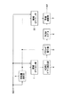
以下に、本発明の実施の形態について説明する。図1は、本発明を適用した、画像変換装置の構成例を示すブロック図である。同図には、例えば画質の悪い(高周波成分が少なくてぼけた画像の)SD画像データ(または、HD画像データ)を、画質改善されたSD画像データ(または、HD画像データ)に変換する構成例が示されている。以下においては、入力画像データがSD画像データである場合について説明する。
【0014】
例えば、画質の悪い(高周波成分が少なくてぼけた画像の)SD画像データが、入力端子を介して画像変換装置に入力される。入力された画像データは、領域切り出し部1、領域切り出し部2、および特徴量抽出部3に供給される。特徴量抽出部3は、入力されたSD画像データのぼけ量を表す特徴量を検出し、その検出した特徴量を領域切り出し部1、領域切り出し部2、およびクラスコード発生部5に出力する。領域切り出し部1は、入力された画像データから所定の範囲の画素データをクラスタップのセットとして切り出し、これをADRC(Adaptive Dynamic Range Coding)パターン抽出部4に出力する。領域切り出し部1において切り出されるクラスタップは、特徴量抽出部3の出力する特徴量に対応して制御される。ADRCパターン抽出部4は、空間内の波形表現を目的としたクラス分類を行うようになされている。
【0015】
クラスコード発生部5は、ADRCパターン抽出部4より出力されたクラスおよび特徴量抽出部3から出力された特徴量に対応するクラスコードを発生し、ROMテーブル6に出力する。ROMテーブル6には、各クラス(クラスコード)に対応して予め所定の予測係数のセットが記憶されており、クラスコードに対応する予測係数のセットが予測演算部7に出力される。
【0016】
領域切り出し部2は、入力された画像データから所定範囲の画素データを予測タップのセットとして切り出し、その予測タップを構成する画素データを予測演算部7に出力する。この領域切り出し部2により切り出される予測タップのセットは、特徴量抽出部3の出力するぼけ量を表す特徴量に対応して制御される。予測演算部7は、領域切り出し部2より入力された予測タップのセットと、ROMテーブル6より入力された予測係数のセットとから予測演算を行い、その演算結果を、画質を補正した画像データとして出力する。この出力された画像データが、例えば図示しない表示デバイスで表示されたり、記録デバイスに記録されたり、伝送デバイスで伝送される。
【0017】
次に、その動作について説明する。領域切り出し部1は、画像データが入力されると、入力された画像データの中から、所定の画素データをクラスタップとして切り出す処理を実行する。例えば、図2に示すように、所定の注目画素データを中心として、その注目画素データに対応する位置のデータ画素と、上下左右に隣接する画素データの合計5個の画素データをクラスタップとして切り出す。あるいは、図3に示すように、注目画素データに対応する画素データと、上下左右方向に3画素分離れた位置に隣接する画素データをクラスタップとして抽出する。どのような画素データがクラスタップとして切り出されるかは、特徴量抽出部3の出力するぼけ量を表す特徴量に対応して決定される。
【0018】
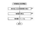
ここで、図4のフローチャートを参照して、特徴量抽出部3の特徴量抽出処理について説明する。最初にステップS1において、特徴量抽出部3は、入力された各画素データに対する自己相関係数をフレーム内の所定の領域(局所)毎に、算出する。そして、この自己相関係数を画素データのぼけ量を表す特徴量の尺度に利用する。
【0019】
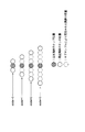
すなわち、例えば図5に示すように、水平方向に連続する3個のタップTAP[0]乃至TAP[2]を自己相関係数算出用のタップとした場合、自己相関係数cc[n](いまの場合、nは3以下の数)は、図6に示すように、タップTAP[0]乃至TAP[2]の画素値と、それをnタップだけシフトした画素値とが、それぞれ積算され、それらが加算されて求められる。すなわち、自己相関係数cc[0]は710(=15×15+14×14+17×17)であり、自己相関係数cc[1]は448(=15×0+14×15+17×14)であり、自己相関係数cc[2]は255(=15×0+14×0+17×15)である。
【0020】
自己相関係数cc[n]の最大値は、図7(A)に示すように、常に自己相関係数cc[0]であり、自己相関係数cc[n]の値はnが増加するとともに減少する。図7は、水平方向に連続する7個のタップTAP[0]乃至TAP[7]を自己相関係数算出用のタップとした場合における自己相関係数cc[n]とnの関係を示しているものであるが、図5および図6に示した例(3個のタップTAP[0]乃至TAP[2]を自己相関係数算出用のタップとした場合)においても、自己相関係数cc[0]が最大値となる。
【0021】
なお、実際には、n個全ての自己相関係数cc[0]乃至cc[n]が算出されるわけではなく、最大値である自己相関係数cc[0]と所定の自己相関係数cc[k](kはn以下の任意の値)との2個の自己相関係数が算出される。
【0022】
ステップS2において、特徴量抽出部3は、図7(A)に示すように、ステップS1で算出した自己相関係数cc[k](図7(A)の例の場合、K=3)を、最大値である自己相関係数cc[0]で割って(正規化して)、正規化された自己相関係数ncc[k](傾斜量)を算出する。
【0023】
ステップS3において、特徴量抽出部3は、ステップS2で算出された正規化された自己相関係数(傾斜量)ncc[k]が、傾斜量の最大値NCQ_MAX(<1.0)乃至最小値NCQ_MIN(>0.0)の間に予め設定されている複数のコード(図7(B)に示す例の場合、0乃至7)のうちのいずれのコードに対応するかを判定し、判定結果に対応するコードを出力する。なお、傾斜量の最大値NCQ_MAXおよび最小値NCQ_MINは、画像データから統計的に設定される。
【0024】
このように、特徴量はコードとして求められ、領域切り出し部1、領域切り出し部2、およびクラスコード発生部5に出力される。
【0025】
領域切り出し部1は、特徴量抽出部3から特徴量として、例えば、コード0が入力された場合、図8に示すように、注目画素に連続して配置されている画素データ(図2に対応する)をクラスタップとして切り出す(抽出する)。また、コード2が入力された場合、領域切り出し部1は、コード0の場合より広い間隔で配置されている画素データ(図8の例では注目画素から2画素離れている画素データ、図3に相当する)をクラスタップとして切り出す(抽出する)。すなわち、特徴量を示すコードが大きくなる(高周波成分が少なく)につれて、注目画素から離れた画素がクラスタップとされる。
【0026】
このように、ぼけ量を表す特徴量(コード)に応じて、クラスタップとして切り出す画素データを局所領域でダイナミックに変化させるようにすることで、より適切なクラスタップを切り出すことが可能となる。
【0027】
図示は省略するが、領域切り出し部2における予測タップも、領域切り出し部1におけるクラスタップの切り出しと同様に、特徴量抽出部3の出力する特徴量に対応して、予測タップとして切り出す画素データをダイナミックに変化させる。なお、この領域切り出し部2において切り出される予測タップ(画素データ)は、領域切り出し部1において切り出されるクラスタップ(画素データ)と同一にしてもよいし、異なるものとしてもよい。
【0028】
ADRCパターン抽出部4は、領域切り出し部1で切り出されたクラスタップに対してADRC処理を実行してクラス分類を行う(クラスを決定する)。すなわち、クラスタップとして抽出された5つの画素データのうちのダイナミックレンジをDR、ビット割当をn、クラスタップとしての各画素データのレベルをL、再量子化コードをQとするとき、次式を演算する。
Q={(L−MIN+0.5)×2 n /DR}
DR=MAX−MIN+1
【0029】
なお、ここで{ }は切り捨て処理を意味する。また、MAXとMINは、クラスタップを構成する5つの画素データ内の最大値と最小値をそれぞれ表している。これにより、例えば領域切り出し部1で切り出されたクラスタップを構成する5個の画素データが、それぞれ例えば8ビット(n=8)で構成されているとすると、これらがそれぞれ2ビットに圧縮される。従って、合計10(=2×5)ビットで表される空間クラスを表すデータが、クラスコード発生部5に供給される。
【0030】
クラスコード発生部5は、ADRCパターン抽出部4より入力された空間クラスを表すデータに、特徴量抽出部3より供給されるぼけ量を表す特徴量を表すビットを付加してクラスコードを発生する。例えば、ぼけ量を表す特徴量が2ビットで表されるとすると、12ビットのクラスコードが発生され、ROMテーブル6に供給される。このクラスコードは、ROMテーブル6のアドレスに対応している。
【0031】
ROMテーブル6には、各クラス(クラスコード)に対応する予測係数のセットがクラスコードに対応するアドレスにそれぞれ記憶されており、クラスコード発生部5より供給されたクラスコードに基づいて、そのクラスコードに対応するアドレスに記憶されている予測係数のセットω1乃至ωnが読み出され、予測演算部7に供給される。
【0032】
予測演算部7は、領域切り出し部2より供給された予測タップを構成する画素データx1乃至xnと、予測係数ω1乃至ωnに対して、次式に示すように、積和演算を行うことで、予測結果yを演算する。
y=ω1x1+ω2x2+・・・+ωnxn
【0033】
この予測値yが、画質(ぼけ)が補正された画素データとなる。
【0034】
図9は、ROMテーブル6に記憶するクラス毎(クラスコード毎)の予測係数のセットを学習によって得るための構成例を表している。この構成例においては、例えば、画質の良好な教師信号(学習信号)としてのSD画像データ(または、HD画像データ)を用いてクラス毎(クラスコード毎)の予測係数のセットを生成する構成が示されている。なお、以下に説明する構成例は、本実施の形態の図1の画像変換装置に対応するクラス毎の予測係数のセットを生成するための例である。
【0035】
例えば、画質の良好な教師信号(学習信号)としての画像データが、正規方程式演算部27に入力されるとともに、ローパスフィルタ(LPF)21に入力される。ローパスフィルタ21は、入力された教師信号(学習信号)としての画像データの低域成分を除去することで、画質の劣化した生徒信号(学習信号)を生成する。ローパスフィルタ21から出力された、画質の劣化した生徒信号(学習信号)は、クラスタップとして所定の範囲の画素データを切り出す(抽出する)領域切り出し部22、予測タップとして所定の範囲の画素データを切り出す(抽出する)領域切り出し部23、および、ぼけ量を表す特徴量を抽出する特徴量抽出部24に入力される。特徴量抽出部24は、入力された画質の劣化した生徒信号(学習信号)の画素データのぼけ量を表す特徴量を抽出し、抽出したその特徴量を、領域切り出し部22、領域切り出し部23、およびクラスコード発生部26に供給する。領域切り出し部22と、領域切り出し部23は、入力されたぼけ量を表す特徴量に対応して、クラスタップ、または予測タップとして切り出す画素データをダイナミックに変化させる。
【0036】
ADRCパターン抽出部25は、領域切り出し部22より入力されたクラスタップとしての画素データのクラス分類を行い(クラスを決定し)、その分類結果をクラスコード発生部26に出力する。クラスコード発生部26は、分類されたクラスとぼけ量を表す特徴量とからクラスコードを発生し、正規方程式演算部27に出力する。なお、上述した領域切り出し部22、領域切り出し部23、特徴量抽出部24、ADRCパターン抽出部25およびクラスコード発生部26のそれぞれの構成および動作は、図1に示された領域切り出し部1、領域切り出し部2、特徴量抽出部3、ADRCパターン抽出部4およびクラスコード発生部6と同一であるため、ここでは説明を省略する。
【0037】
正規方程式演算部27は、入力される教師信号(学習信号)と領域切り出し部23から供給される予測タップとしての画素データとから、クラス毎(クラスコード毎)に正規方程式を生成し、その正規方程式を予測係数決定部28に供給する。そして、クラス毎に必要な数の正規方程式が求められたとき、正規方程式演算部27は、例えば、クラス毎に最小自乗法を用いて正規方程式を解き、クラス毎の予測係数のセットを演算する。求められたクラス毎の予測係数のセットは、予測係数決定部28からメモリ29に供給され、記憶される。このメモリ29に記憶されたクラス毎の予測係数のセットが、図1のROMテーブル6に書き込まれることになる。
【0038】
上述した例では、クラス毎の予測係数のセットを、図9に示される構成によって演算して求めるようにしたが、コンピュータを用いてシミュレーションで演算して求めるようにしてもよい。
【0039】
また、本実施の形態においては、図1に示されるROMテーブル6に記憶された、図9に示される方法で演算されたクラス毎の予測係数のセットと、予測タップとして切り出された画素データとから画質改善(ぼけ改善)された画素データを生成するようになされているが、本発明はこれに限らず、ROMテーブル6に学習によって演算されたクラス毎(クラスコード毎)の画素データの予測値そのものを記憶しておき、クラスコードによってその予測値を読み出すようにしてもよい。
【0040】
この場合、図1に示される領域切り出し部2および図9に示される領域切り出し部23は省略でき、図1に示される予測演算部7は、ROMテーブル6から出力された画素データを出力デバイスに対応したフォーマットに変換して出力するようになされる。さらに、この場合は、図9に示される正規方程式演算部27および予測係数決定部28のかわりに、重心法を用いてクラス毎の予測値が生成され、このクラス毎の予測値がメモリ29に記憶される。
【0041】
さらに、クラス毎の予測値そのもののかわりに、クラス毎の予測値のそれぞれを基準値で正規化し、クラス毎の正規化された予測値をROMテーブル6に記憶しておいてもよい。この場合、図1に示される予測演算部7では、基準値に基づいて正規化された予測値から予測値を演算することになる。
【0042】
さらに、本実施の形態において、クラスタップまたは予測タップとして切り出される画素データの数は、5個であったが、これに限らず、クラスタップまたは予測タップとして切り出される画素データの数はいくつであってもよい。ただし、クラスタップまたは予測タップとして切り出す数を多くすればするほど画質改善の精度は高くなるが、演算量が多くなり、メモリが大きくなり、演算量、ハード面での負荷が大きくなるため、最適な数を設定する必要がある。
【0043】
また、本実施の形態においては、SD画像信号からSD画像信号への変換(SD−SD変換)、HD画像信号からHD画像信号への変換(HD−HD変換)について説明されているが、本発明はこれに限らず、他のフォーマット(インターレース信号、ノンインターレース信号など)の変換にももちろん適用可能である。さらに、SD画像信号からHD画像信号への変換(SD−HD変換)やインターレース信号からノンインターレース信号への変換(インター−ノンインター変換)など、異なるフォーマット間の変換にも本発明は適用が可能である。ただし、この場合には、クラスタップまたは予測タップとして画像データを切り出す際には、注目画素データとなる画素は実際には存在しないため、切り出しの対象画素データとはならない。
【0044】
なお、本発明の主旨を逸脱しない範囲において、さまざまな変形や応用例が考えられる。従って、本発明の要旨は本実施の形態に限定されるものではない。
【0045】
また、上記したような処理を行うコンピュータプログラムをユーザに提供する提供媒体としては、磁気ディスク、CD-ROM、固体メモリなどの記録媒体の他、ネットワーク、衛星などの通信媒体を利用することができる。
【0046】
【発明の効果】
以上のように、本発明によれば、入力される画像データの画質が悪くても、クラスタップまたは予測タップとして最適な画素データを抽出することができ、適切な予測処理を行うことが可能となる。
【図面の簡単な説明】
【図1】本発明を適用した画像変換装置の構成を示すブロック図である。
【図2】図1の領域切り出し部1における切り出し処理を説明する図である。
【図3】図1の領域切り出し部1における切り出し処理を説明する図である。
【図4】図1の特徴量抽出部3における特徴量抽出処理を説明するフローチャートである。
【図5】図4のステップS1における自己相関係数の演算を説明する図である。
【図6】図4のステップS1における自己相関係数の演算を説明する図である。
【図7】図4のステップS2の正規化処理を説明する図である。
【図8】コードの対応するクラスタップの例を示す図である。
【図9】図1のROMテーブル6の予測係数の学習処理を行うための構成を示すブロック図である。
【符号の説明】
1,2 領域切り出し部, 3 特徴量抽出部, 4 ADRCパターン抽出部,
5 クラスコード発生部, 6 ROMテーブル, 7 予測演算部[0001]
BACKGROUND OF THE INVENTION
The present invention relates to an image conversion apparatus and method, andRecordRegarding media, in particular, when an input image signal is converted to an image signal of the same format or a different format, even if the image quality of the input image data is poor, the image is surely corrected or improved in image quality Image conversion apparatus and method capable of providing signal, andRecordIt relates to the medium.
[0002]
[Prior art]
For example, Japanese Patent Laid-Open No. 8-51599 proposes a technique for obtaining higher resolution pixel data. In this proposal, for example, when creating image data composed of HD (High Definition) pixel data from image data composed of SD (Standard Definition) pixel data, SD pixel data located in the vicinity of the created HD pixel data is used. Perform class classification (determine the class), learn the prediction coefficient value for each class, use the in-screen (spatial) correlation in the image still part, and in the field in the motion part By using the correlation, HD pixel data closer to the true value is obtained.
[0003]
[Problems to be solved by the invention]
By the way, using this technique, for example, it is possible to correct an image with very poor image quality (blurred image) into an image with good image quality. However, in the case of image data with very poor image quality (having lost high-frequency components), if class classification is performed using image data with very poor image quality, appropriate class classification cannot be performed. Class cannot be determined. If an appropriate class cannot be obtained, an appropriate set of prediction coefficient values cannot be obtained, and eventually there has been a problem that sufficient image quality correction cannot be performed.
[0004]
The present invention has been made in view of such circumstances, and makes it possible to reliably correct the image quality even if the image quality of the input image data is poor.
[0005]
[Means for Solving the Problems]
The present inventionThe image conversion apparatus includes a plurality of pixel data constituting the first image signal.Among them, one pixel data is designated as the target pixel data, and a plurality of pixel data located around the target pixel data is composed of a plurality of pixel data for generating a class code corresponding to the target pixel data.First extraction means for extracting as a class tap;Data is compressed as a result of compressing multiple pixel data that make up a class tap.TheAny classClassificationAnd classifiedA classifying means for generating a class code representing a class;For multiple pixel data that make up a class tap ADRC By doing the processing,Class tapAny classClassificationAnd classifiedA classifying means for generating a class code representing a class;It was generated from the table where the prediction coefficient is recorded in association with the class code.Prediction coefficient corresponding to class coderead outPrediction coefficient generating means and first image signalAmong the plurality of pixel data constituting the pixel, the pixel data is designated as the target pixel data, and the plurality of pixel data located around the target pixel is generated to generate the pixel data constituting the second image signal Composed of multiple pixel dataPrediction tapAsSecond extracting means for extracting;Read outWith prediction factorExtractedPrediction tapBy multiplying and multiplying multiple pixel dataThe second image signalConfigure the pixel dataGeneration means for generating and local autocorrelation of the first image signalAutocorrelation shifted by a predetermined amount in the functionCalculation means for calculating coefficients and calculationWasAutocorrelation coefficientThe larger the value ofFirst extraction meansExtracted byClass tap or second extraction meansExtracted byPrediction tapTo expand the extraction range of at least one ofAnd a control means for controlling.
[0006]
The present inventionThe image conversion method includes a plurality of pixel data constituting the first image signal.Among them, one pixel data is designated as the target pixel data, and a plurality of pixel data located around the target pixel data is composed of a plurality of pixel data for generating a class code corresponding to the target pixel data.A first extraction step for extracting as a class tap;Data is compressed as a result of compressing multiple pixel data that make up a class tap.TheAny classClassificationAnd classifiedA classification step for generating a class code representing the class;For multiple pixel data that make up a class tap ADRC By doing the processing,Class tapAny classClassificationAnd classifiedA classification step for generating a class code representing the class;It was generated from the table where the prediction coefficient is recorded in association with the class code.Prediction coefficient corresponding to class coderead outPrediction coefficient generation step and first image signalAmong the plurality of pixel data constituting the pixel, the pixel data is designated as the target pixel data, and the plurality of pixel data located around the target pixel is generated to generate the pixel data constituting the second image signal Composed of multiple pixel dataPrediction tapAsA second extraction step to extract;Read outWith prediction factorExtractedPrediction tapBy multiplying and multiplying multiple pixel dataThe second image signalConfigure the pixel dataGeneration step to generate and local autocorrelation of the first image signalAutocorrelation shifted by a predetermined amount in the functionCalculation steps for calculating coefficients and calculationWasAutocorrelation coefficientThe larger the value ofIn the first extraction stepExtractedIn the class tap or the second extraction stepExtractedPrediction tapTo expand the extraction range of at least one ofAnd a control step for controlling.
[0007]
Record of the present inventionThe medium is a plurality of pixel data constituting the first image signalAmong them, one pixel data is designated as the target pixel data, and a plurality of pixel data located around the target pixel data is composed of a plurality of pixel data for generating a class code corresponding to the target pixel data.A first extraction step for extracting as a class tap;Data is compressed as a result of compressing multiple pixel data that make up a class tap.TheAny classClassificationAnd classifiedA classification step for generating a class code representing the class;It was generated from the table where the prediction coefficient is recorded in association with the class code.Prediction coefficient corresponding to class coderead outPrediction coefficient generation step and first image signalAmong the plurality of pixel data constituting the pixel, the pixel data is designated as the target pixel data, and the plurality of pixel data located around the target pixel is generated to generate the pixel data constituting the second image signal Composed of multiple pixel dataPrediction tapAsA second extraction step to extract;Read outWith prediction factorExtractedPrediction tapBy multiplying and multiplying multiple pixel dataThe second image signalConfigure the pixel dataGeneration step to generate and local autocorrelation of the first image signalAutocorrelation shifted by a predetermined amount in the functionCalculation steps for calculating coefficients and calculationWasAutocorrelation coefficientThe larger the value ofIn the first extraction stepExtractedIn the class tap or the second extraction stepExtractedPrediction tapTo expand the extraction range of at least one ofControl steps to control andA program for causing the computer of the image conversion apparatus to execute processing including the above is recorded.
[0008]
Image conversion apparatus and method, and recording medium program of the present inventionInAmong the plurality of pixel data constituting the first image signal, one pixel data is designated as the target pixel data, and the plurality of pixel data located around the target pixel data has a class code corresponding to the target pixel data. It is extracted as a class tap consisting of a plurality of pixel data for generation, compression processing is applied to the plurality of pixel data constituting the class tap, and the data of the compression processing result is assigned to any classClassificationAnd classifiedA class code representing the class is generated,The prediction coefficient corresponding to the generated class code is read from the table in which the prediction coefficient is recorded in association with the class code. In addition, among the plurality of pixel data constituting the first image signal, one pixel data is designated as the target pixel data, and the plurality of pixel data positioned around the target pixel constitutes the second image signal. Extracted as a prediction tap composed of a plurality of pixel data for generating pixel data, and a second sum is calculated by multiplying the read prediction coefficient and the plurality of pixel data constituting the extracted prediction tap. Pixel data constituting the image signal is generated. Then, an autocorrelation coefficient shifted by a predetermined amount in the local autocorrelation function of the first image signal is calculated. As the calculated autocorrelation coefficient is larger, the extracted class tap or the extracted The extraction range of at least one of the prediction taps is expanded.
[0009]
Claim5And an image conversion method according to claim 1.6In the providing medium described in the above, a plurality of image data for generating a class code is extracted from the first image signal as a class tap in the first extraction step, and the class tap is classified into a class in the class classification step. A class code representing the class is generated by classification, a prediction coefficient corresponding to the class code is generated in the prediction coefficient generation step, and a prediction tap is extracted from the first image signal in the second extraction step And generating a second image signal using the prediction coefficient and the prediction tap in the generation step, calculating a local autocorrelation coefficient of the first image signal in the calculation step,controlIn step, autocorrelation coefficient calculated in calculation stepOn the basis of the,The class tap extracted in the first extraction step or the prediction tap extracted in the second extraction step is controlled.
[0010]
DETAILED DESCRIPTION OF THE INVENTION
Embodiments of the present invention will be described below, but in order to clarify the correspondence between each means of the invention described in the claims and the following embodiments, in parentheses after each means, The features of the present invention will be described with the corresponding embodiment (however, an example) added.
[0011]
That is,The present inventionThe image conversion apparatus includes a plurality of pixel data constituting the first image signal.Among them, one pixel data is designated as the target pixel data, and a plurality of pixel data located around the target pixel data is composed of a plurality of pixel data for generating a class code corresponding to the target pixel data.First extraction means (for example, the
[0012]
However, of course, this description does not mean that each means is limited to the description.
[0013]
Embodiments of the present invention will be described below. FIG. 1 is a block diagram illustrating a configuration example of an image conversion apparatus to which the present invention is applied. In the figure, for example, SD image data (or HD image data) with poor image quality (blurred image with few high-frequency components) is converted to SD image data (or HD image data) with improved image quality. An example is shown. Hereinafter, a case where the input image data is SD image data will be described.
[0014]
For example, SD image data with a poor image quality (a blurred image with few high-frequency components) is input to the image conversion apparatus via the input terminal. The input image data is supplied to the
[0015]
The class
[0016]
The
[0017]
Next, the operation will be described. When the image data is input, the
[0018]
Here, the feature amount extraction processing of the feature
[0019]
That is, for example, as shown in FIG. 5, when three taps TAP [0] to TAP [2] continuous in the horizontal direction are used as taps for calculating the autocorrelation coefficient, the autocorrelation coefficient cc [n] ( In this case, n is a number of 3 or less), as shown in FIG. 6, the pixel values of the taps TAP [0] to TAP [2] and the pixel values shifted by n taps are respectively integrated. , They are added and determined. That is, the autocorrelation coefficient cc [0] is 710 (= 15 × 15 + 14 × 14 + 17 × 17), the autocorrelation coefficient cc [1] is 448 (= 15 × 0 + 14 × 15 + 17 × 14), and the self-phase The relation number cc [2] is 255 (= 15 × 0 + 14 × 0 + 17 × 15).
[0020]
As shown in FIG. 7A, the maximum value of the autocorrelation coefficient cc [n] is always the autocorrelation coefficient cc [0], and the value of the autocorrelation coefficient cc [n] increases by n. Decreases with time. FIG. 7 shows the relationship between autocorrelation coefficient cc [n] and n when seven taps TAP [0] to TAP [7] that are continuous in the horizontal direction are used as taps for calculating the autocorrelation coefficient. However, in the example shown in FIGS. 5 and 6 (when the three taps TAP [0] to TAP [2] are taps for calculating the autocorrelation coefficient), the autocorrelation coefficient cc [0] is the maximum value.
[0021]
Actually, not all n autocorrelation coefficients cc [0] to cc [n] are calculated, but the autocorrelation coefficient cc [0] which is the maximum value and a predetermined autocorrelation coefficient Two autocorrelation coefficients with cc [k] (k is an arbitrary value less than or equal to n) are calculated.
[0022]
In step S2, the feature
[0023]
In step S3, the feature
[0024]
In this way, the feature amount is obtained as a code, and is output to the
[0025]
For example, when a
[0026]
As described above, it is possible to cut out more appropriate class taps by dynamically changing the pixel data to be cut out as class taps in the local region in accordance with the feature amount (code) representing the blur amount.
[0027]
Although illustration is omitted, the prediction tap in the
[0028]
The ADRC
Q = {(L−MIN + 0.5) ×2 n / DR}
DR = MAX−
[0029]
Here, {} means a truncation process. MAX and MIN represent the maximum value and the minimum value in the five pixel data constituting the class tap, respectively. Thus, for example, if the five pixel data constituting the class tap cut out by the
[0030]
The class
[0031]
In the ROM table 6, a set of prediction coefficients corresponding to each class (class code) is stored at an address corresponding to the class code. Based on the class code supplied from the class
[0032]
The
y = ω1x1+ Ω2x2+ ... + ωnxn
[0033]
This predicted value y becomes pixel data with corrected image quality (blur).
[0034]
FIG. 9 shows a configuration example for obtaining a set of prediction coefficients for each class (for each class code) stored in the ROM table 6 by learning. In this configuration example, for example, a configuration in which a set of prediction coefficients for each class (for each class code) is generated using SD image data (or HD image data) as a teacher signal (learning signal) with good image quality. It is shown. Note that the configuration example described below is an example for generating a set of prediction coefficients for each class corresponding to the image conversion apparatus in FIG. 1 of the present embodiment.
[0035]
For example, image data as a teacher signal (learning signal) with good image quality is input to the normal equation calculation unit 27 and also input to the low-pass filter (LPF) 21. The low-
[0036]
The ADRC
[0037]
The normal equation calculation unit 27 generates a normal equation for each class (for each class code) from the input teacher signal (learning signal) and pixel data as a prediction tap supplied from the
[0038]
In the above-described example, the set of prediction coefficients for each class is calculated and calculated by the configuration shown in FIG. 9, but may be calculated and calculated by simulation using a computer.
[0039]
Further, in the present embodiment, a set of prediction coefficients for each class calculated by the method shown in FIG. 9 stored in the ROM table 6 shown in FIG. 1, pixel data cut out as a prediction tap, and However, the present invention is not limited to this, and prediction of pixel data for each class (each class code) calculated by learning in the ROM table 6 is performed. The value itself may be stored, and the predicted value may be read by the class code.
[0040]
In this case, the
[0041]
Furthermore, instead of the predicted value itself for each class, each predicted value for each class may be normalized with a reference value, and the normalized predicted value for each class may be stored in the ROM table 6. In this case, the
[0042]
Furthermore, in this embodiment, the number of pixel data cut out as class taps or prediction taps is five, but the number of pixel data cut out as class taps or prediction taps is not limited to this. May be. However, the more the number of class taps or prediction taps to be extracted, the higher the accuracy of image quality improvement. However, the amount of computation increases, the memory becomes larger, and the amount of computation and hardware increases. It is necessary to set a large number.
[0043]
In the present embodiment, conversion from an SD image signal to an SD image signal (SD-SD conversion) and conversion from an HD image signal to an HD image signal (HD-HD conversion) are described. The invention is not limited to this, and can be applied to conversion of other formats (interlace signal, non-interlace signal, etc.). Furthermore, the present invention can also be applied to conversion between different formats such as conversion from SD image signals to HD image signals (SD-HD conversion) and conversion from interlace signals to non-interlace signals (inter-non-inter conversion). It is. However, in this case, when image data is cut out as a class tap or a prediction tap, there is actually no pixel that is pixel-of-interest data.
[0044]
Various modifications and application examples can be considered without departing from the gist of the present invention. Therefore, the gist of the present invention is not limited to the present embodiment.
[0045]
Further, as a providing medium for providing a computer program for performing the processing as described above to a user, a communication medium such as a network or a satellite can be used in addition to a recording medium such as a magnetic disk, a CD-ROM, or a solid memory. .
[0046]
【The invention's effect】
As aboveThe present inventionAccording toEnterEven if the image quality of the input image data is poor, the optimum pixel data can be extracted as a class tap or a prediction tap, and an appropriate prediction process can be performed.
[Brief description of the drawings]
FIG. 1 is a block diagram illustrating a configuration of an image conversion apparatus to which the present invention is applied.
FIG. 2 is a diagram for explaining cutout processing in a
FIG. 3 is a diagram for explaining cut-out processing in a region cut-out
FIG. 4 is a flowchart for explaining feature amount extraction processing in a feature
FIG. 5 is a diagram for explaining calculation of an autocorrelation coefficient in step S1 of FIG.
6 is a diagram for explaining calculation of an autocorrelation coefficient in step S1 of FIG.
FIG. 7 is a diagram for explaining the normalization process in step S2 of FIG.
FIG. 8 is a diagram illustrating an example of a class tap corresponding to a code.
9 is a block diagram showing a configuration for performing learning processing of a prediction coefficient of the ROM table 6 of FIG.
[Explanation of symbols]
1, 2 area segmentation unit, 3 feature extraction unit, 4 ADRC pattern extraction unit,
5 Class code generator, 6 ROM table, 7 Predictive calculator
Claims (5)
前記第1の画像信号を構成する複数の画素データのうち、1つの画素データを注目画素データに指定し、前記注目画素データの周辺に位置する複数の画素データを、前記注目画素データに対応するクラスコードを生成するための複数の画素データからなるクラスタップとして抽出する第1の抽出手段と、
前記クラスタップを構成する複数の画素データに対して圧縮処理を行い、前記圧縮処理結果のデータをいずれかのクラスに分類し、分類したクラスを表すクラスコードを発生するクラス分類手段と、
前記クラスコードに対応付けて予測係数が記録されているテーブルから、発生された前記クラスコードに対応する前記予測係数を読み出す予測係数発生手段と、
前記第1の画像信号を構成する複数の画素データのうち、1つの画素データを注目画素データに指定し、前記注目画素の周辺に位置する複数の画素データを、前記第2の画像信号を構成する画素データを生成するための複数の画素データからなる予測タップとして抽出する第2の抽出手段と、
読み出された前記予測係数と抽出された前記予測タップを構成する複数の画素データとを積和演算することにより前記第2の画像信号を構成する画素データを生成する生成手段と、
前記第1の画像信号の局所的な自己相関関数における、所定量だけシフトした自己相関係数を演算する演算手段と、
演算された前記自己相関係数の値が大きい程、前記第1の抽出手段によって抽出される前記クラスタップまたは前記第2の抽出手段によって抽出される前記予測タップの少なくとも一方の抽出範囲を広げるように制御する制御手段と
を備えることを特徴とする画像変換装置。In an image conversion apparatus for converting a first image signal composed of a plurality of pixel data into a second image signal which is a signal whose image quality is improved from that of the first image signal composed of a plurality of pixel data,
Among the plurality of pixel data constituting the first image signal , one pixel data is designated as the target pixel data, and the plurality of pixel data located around the target pixel data corresponds to the target pixel data. First extraction means for extracting as a class tap composed of a plurality of pixel data for generating a class code ;
It performs compression processing for a plurality of pixel data constituting the class tap, and class classification means for classifying the data of the compression processing result into any class, generating a class code representing the class obtained by classifying,
Prediction coefficient generation means for reading the prediction coefficient corresponding to the generated class code from the table in which the prediction coefficient is recorded in association with the class code;
Among the plurality of pieces of pixel data constituting the first image signal , one piece of pixel data is designated as target pixel data, and a plurality of pieces of pixel data located around the target pixel are formed as the second image signal. Second extraction means for extracting as a prediction tap comprising a plurality of pixel data for generating pixel data to be performed ;
Generating means for generating pixel data constituting the second image signal by performing a product-sum operation on the read prediction coefficient and the plurality of pixel data constituting the extracted prediction tap;
A computing means for computing an autocorrelation coefficient shifted by a predetermined amount in the local autocorrelation function of the first image signal;
As the value of the computed the autocorrelation coefficient is large, so to expand at least one of the extraction range of the prediction taps extracted by the class tap or the second extraction means is extracted by said first extraction means And a control means for controlling the image conversion apparatus.
前記正規化手段で正規化された前記自己相関係数に対応して前記第1の画像信号の統計的な特徴量を表すコードを発生するコード発生手段と
をさらに備え、
前記制御手段は、前記コード発生手段によって発生された前記コードにも対応して前記第1の抽出手段によって抽出される前記クラスタップまたは前記第2の抽出手段によって抽出される前記予測タップの少なくとも一方の抽出範囲の広さを制御する
ことを特徴とする請求項1に記載の画像変換装置。Normalizing means for normalizing the autocorrelation coefficient calculated by the calculating means to a value in a predetermined range ;
Code generating means for generating a code representing a statistical feature quantity of the first image signal corresponding to the autocorrelation coefficient normalized by the normalizing means; and
Wherein, at least one of the prediction taps extracted by the class tap or the second extraction means is extracted by said also supports the code generated first extraction means by said code generating means The image conversion apparatus according to claim 1, wherein the width of the extraction range of the image is controlled.
前記第1の画像信号を構成する複数の画素データのうち、1つの画素データを注目画素データに指定し、前記注目画素データの周辺に位置する複数の画素データを、前記注目画素データに対応するクラスコードを生成するための複数の画素データからなるクラスタップとして抽出する第1の抽出ステップと、
前記クラスタップを構成する複数の画素データに対して圧縮処理を行い、前記圧縮処理結果のデータをいずれかのクラスに分類し、分類したクラスを表すクラスコードを発生するクラス分類ステップと、
前記クラスコードに対応付けて予測係数が記録されているテーブルから、発生された前記クラスコードに対応する前記予測係数を読み出す予測係数発生ステップと、
前記第1の画像信号を構成する複数の画素データのうち、1つの画素データを注目画素データに指定し、前記注目画素の周辺に位置する複数の画素データを、前記第2の画像信号を構成する画素データを生成するための複数の画素データからなる予測タップとして抽出する第2の抽出ステップと、
読み出された前記予測係数と抽出された前記予測タップを構成する複数の画素データとを積和演算することにより前記第2の画像信号を構成する画素データを生成する生成ステップと、
前記第1の画像信号の局所的な自己相関関数における、所定量だけシフトした自己相関係数を演算する演算ステップと、
演算された前記自己相関係数の値が大きい程、前記第1の抽出ステップで抽出される前記クラスタップまたは前記第2の抽出ステップで抽出される前記予測タップの少なくとも一方の抽出範囲を広げるように制御する制御ステップと
を含むことを特徴とする画像変換方法。In an image conversion method of an image conversion apparatus for converting a first image signal composed of a plurality of pixel data into a second image signal which is a signal whose image quality is improved from that of the first image signal composed of a plurality of pixel data,
Among the plurality of pixel data constituting the first image signal , one pixel data is designated as the target pixel data, and the plurality of pixel data located around the target pixel data corresponds to the target pixel data. A first extraction step of extracting as a class tap comprising a plurality of pixel data for generating a class code ;
Performs compression processing for a plurality of pixel data constituting the class tap, and the classification step of the data compression processing results are classified into one of classes, for generating a class code representing the class classified,
A prediction coefficient generation step of reading out the prediction coefficient corresponding to the generated class code from the table in which the prediction coefficient is recorded in association with the class code;
Among the plurality of pieces of pixel data constituting the first image signal , one piece of pixel data is designated as target pixel data, and a plurality of pieces of pixel data located around the target pixel are formed as the second image signal. A second extraction step of extracting as a prediction tap composed of a plurality of pixel data for generating pixel data to be performed ;
A generation step of generating pixel data constituting the second image signal by performing a product-sum operation on the read prediction coefficient and the plurality of pixel data constituting the extracted prediction tap;
A calculation step of calculating an autocorrelation coefficient shifted by a predetermined amount in the local autocorrelation function of the first image signal;
As the value of the computed the autocorrelation coefficient is large, so to expand at least one of the extraction range of the prediction taps extracted by the first of the class tap or the second extraction step is extracted in the extraction step And a control step for controlling the image.
前記第1の画像信号を構成する複数の画素データのうち、1つの画素データを注目画素データに指定し、前記注目画素データの周辺に位置する複数の画素データを、前記注目画素データに対応するクラスコードを生成するための複数の画素データからなるクラスタップとして抽出する第1の抽出ステップと、
前記クラスタップを構成する複数の画素データに対して圧縮処理を行い、前記圧縮処理結果のデータをいずれかのクラスに分類し、分類したクラスを表すクラスコードを発生するクラス分類ステップと、
前記クラスコードに対応付けて予測係数が記録されているテーブルから、発生された前記クラスコードに対応する前記予測係数を読み出す予測係数発生ステップと、
前記第1の画像信号を構成する複数の画素データのうち、1つの画素データを注目画素データに指定し、前記注目画素の周辺に位置する複数の画素データを、前記第2の画像信号を構成する画素データを生成するための複数の画素データからなる予測タップとして抽出する第2の抽出ステップと、
読み出された前記予測係数と抽出された前記予測タップを構成する複数の画素データとを積和演算することにより前記第2の画像信号を構成する画素データを生成する生成ステップと、
前記第1の画像信号の局所的な自己相関関数における、所定量だけシフトした自己相関係数を演算する演算ステップと、
演算された前記自己相関係数の値が大きい程、前記第1の抽出ステップで抽出される前記クラスタップまたは前記第2の抽出ステップで抽出される前記予測タップの少なくとも一方の抽出範囲を広げるように制御する制御ステップと
を含む処理を画像変換装置のコンピュータに実行させるプログラムが記録されていることを特徴とする記録媒体。 A program for controlling an image conversion apparatus for converting a first image signal composed of a plurality of pixel data into a second image signal which is a signal whose image quality is improved from that of the first image signal composed of a plurality of pixel data. And
Among the plurality of pixel data constituting the first image signal , one pixel data is designated as the target pixel data, and the plurality of pixel data located around the target pixel data corresponds to the target pixel data. A first extraction step of extracting as a class tap comprising a plurality of pixel data for generating a class code ;
Performs compression processing for a plurality of pixel data constituting the class tap, and the classification step of the data compression processing results are classified into one of classes, for generating a class code representing the class classified,
A prediction coefficient generation step of reading out the prediction coefficient corresponding to the generated class code from the table in which the prediction coefficient is recorded in association with the class code;
Among the plurality of pieces of pixel data constituting the first image signal , one piece of pixel data is designated as target pixel data, and a plurality of pieces of pixel data located around the target pixel are formed as the second image signal. A second extraction step of extracting as a prediction tap composed of a plurality of pixel data for generating pixel data to be performed ;
A generation step of generating pixel data constituting the second image signal by performing a product-sum operation on the read prediction coefficient and the plurality of pixel data constituting the extracted prediction tap;
A calculation step of calculating an autocorrelation coefficient shifted by a predetermined amount in the local autocorrelation function of the first image signal;
As the value of the computed the autocorrelation coefficient is large, so to expand at least one of the extraction range of the prediction taps extracted by the first of the class tap or the second extraction step is extracted in the extraction step and a control step of controlling the
A recording medium on which is recorded a program that causes a computer of an image conversion apparatus to execute processing including the above.
Priority Applications (1)
| Application Number | Priority Date | Filing Date | Title |
|---|---|---|---|
| JP19527798A JP4035895B2 (en) | 1998-07-10 | 1998-07-10 | Image conversion apparatus and method, and recording medium |
Applications Claiming Priority (1)
| Application Number | Priority Date | Filing Date | Title |
|---|---|---|---|
| JP19527798A JP4035895B2 (en) | 1998-07-10 | 1998-07-10 | Image conversion apparatus and method, and recording medium |
Publications (3)
| Publication Number | Publication Date |
|---|---|
| JP2000032402A JP2000032402A (en) | 2000-01-28 |
| JP2000032402A5 JP2000032402A5 (en) | 2005-09-02 |
| JP4035895B2 true JP4035895B2 (en) | 2008-01-23 |
Family
ID=16338493
Family Applications (1)
| Application Number | Title | Priority Date | Filing Date |
|---|---|---|---|
| JP19527798A Expired - Fee Related JP4035895B2 (en) | 1998-07-10 | 1998-07-10 | Image conversion apparatus and method, and recording medium |
Country Status (1)
| Country | Link |
|---|---|
| JP (1) | JP4035895B2 (en) |
Families Citing this family (8)
| Publication number | Priority date | Publication date | Assignee | Title |
|---|---|---|---|---|
| US7573508B1 (en) | 1999-02-19 | 2009-08-11 | Sony Corporation | Image signal processing apparatus and method for performing an adaptation process on an image signal |
| JP4547758B2 (en) * | 1999-03-25 | 2010-09-22 | ソニー株式会社 | Image signal processing apparatus, image signal processing method, learning apparatus, learning method, and recording medium |
| JP4547757B2 (en) * | 1999-03-25 | 2010-09-22 | ソニー株式会社 | Image signal processing apparatus, image signal processing method, learning apparatus, learning method, and recording medium |
| JP2001222702A (en) * | 2000-02-07 | 2001-08-17 | Sony Corp | Device and method for image processing and recording medium |
| JP4596196B2 (en) * | 2000-08-02 | 2010-12-08 | ソニー株式会社 | Digital signal processing method, learning method and apparatus, and program storage medium |
| JP4538705B2 (en) | 2000-08-02 | 2010-09-08 | ソニー株式会社 | Digital signal processing method, learning method and apparatus, and program storage medium |
| JP4596197B2 (en) | 2000-08-02 | 2010-12-08 | ソニー株式会社 | Digital signal processing method, learning method and apparatus, and program storage medium |
| JP4854042B2 (en) * | 2008-08-12 | 2012-01-11 | Necエンジニアリング株式会社 | Image generation method, image generation apparatus, and image generation program |
-
1998
- 1998-07-10 JP JP19527798A patent/JP4035895B2/en not_active Expired - Fee Related
Also Published As
| Publication number | Publication date |
|---|---|
| JP2000032402A (en) | 2000-01-28 |
Similar Documents
| Publication | Publication Date | Title |
|---|---|---|
| US6678405B1 (en) | Data processing apparatus, data processing method, learning apparatus, learning method, and medium | |
| US6766059B1 (en) | Image processing apparatus | |
| US6233019B1 (en) | Image converter and image converting method for improving image quality | |
| JP4362895B2 (en) | Data processing apparatus, data processing method, and recording medium | |
| JP4035895B2 (en) | Image conversion apparatus and method, and recording medium | |
| US20090161947A1 (en) | Image processing device and method, learning device and method, program, and recording medium | |
| US5949916A (en) | Modified automatic regressive filter and filtering method therefor | |
| JP3486975B2 (en) | Noise reduction apparatus and method | |
| JP2000148724A (en) | Processor and method for data processing | |
| JP4062771B2 (en) | Image conversion apparatus and method, and recording medium | |
| JP4324825B2 (en) | Data processing apparatus, data processing method, and medium | |
| US7061539B2 (en) | Information signal processing device, information signal processing method, image signal processing device, image display comprising the same, and information providing medium | |
| JP4139979B2 (en) | Image conversion apparatus and method, and recording medium | |
| JP3890638B2 (en) | Image information conversion apparatus and method | |
| JP4135045B2 (en) | Data processing apparatus, data processing method, and medium | |
| US7770098B2 (en) | Signal processing apparatus and method therefor | |
| JP4131303B2 (en) | Image conversion apparatus and method, learning apparatus and method, image conversion system, and recording medium | |
| JP4337186B2 (en) | Image information conversion apparatus, image information conversion method, learning apparatus, and learning method | |
| JP3243861B2 (en) | Image information conversion device | |
| JP4225039B2 (en) | Data processing apparatus and method, recording medium, and program | |
| WO2000048198A1 (en) | Preprocessing peripheral erroneous data, method and apparatus | |
| JP4062326B2 (en) | Coefficient generation apparatus and method | |
| JP4447671B2 (en) | Image signal converting apparatus and method, and neural network coupling coefficient generating apparatus and generating method used therefor | |
| JP4415229B2 (en) | Image processing apparatus and method, and recording medium | |
| JPH09319730A (en) | Product sum arithmetic circuit and its method |
Legal Events
| Date | Code | Title | Description |
|---|---|---|---|
| A521 | Request for written amendment filed |
Free format text: JAPANESE INTERMEDIATE CODE: A523 Effective date: 20050303 |
|
| A621 | Written request for application examination |
Free format text: JAPANESE INTERMEDIATE CODE: A621 Effective date: 20050303 |
|
| A131 | Notification of reasons for refusal |
Free format text: JAPANESE INTERMEDIATE CODE: A131 Effective date: 20070720 |
|
| A521 | Request for written amendment filed |
Free format text: JAPANESE INTERMEDIATE CODE: A523 Effective date: 20070913 |
|
| TRDD | Decision of grant or rejection written | ||
| A01 | Written decision to grant a patent or to grant a registration (utility model) |
Free format text: JAPANESE INTERMEDIATE CODE: A01 Effective date: 20071009 |
|
| A61 | First payment of annual fees (during grant procedure) |
Free format text: JAPANESE INTERMEDIATE CODE: A61 Effective date: 20071022 |
|
| FPAY | Renewal fee payment (event date is renewal date of database) |
Free format text: PAYMENT UNTIL: 20101109 Year of fee payment: 3 |
|
| FPAY | Renewal fee payment (event date is renewal date of database) |
Free format text: PAYMENT UNTIL: 20111109 Year of fee payment: 4 |
|
| FPAY | Renewal fee payment (event date is renewal date of database) |
Free format text: PAYMENT UNTIL: 20111109 Year of fee payment: 4 |
|
| FPAY | Renewal fee payment (event date is renewal date of database) |
Free format text: PAYMENT UNTIL: 20121109 Year of fee payment: 5 |
|
| FPAY | Renewal fee payment (event date is renewal date of database) |
Free format text: PAYMENT UNTIL: 20121109 Year of fee payment: 5 |
|
| FPAY | Renewal fee payment (event date is renewal date of database) |
Free format text: PAYMENT UNTIL: 20131109 Year of fee payment: 6 |
|
| R250 | Receipt of annual fees |
Free format text: JAPANESE INTERMEDIATE CODE: R250 |
|
| LAPS | Cancellation because of no payment of annual fees |