JP4034322B2 - Connection structure of wood and structure for wooden building using the same - Google Patents
Connection structure of wood and structure for wooden building using the same Download PDFInfo
- Publication number
- JP4034322B2 JP4034322B2 JP2005188487A JP2005188487A JP4034322B2 JP 4034322 B2 JP4034322 B2 JP 4034322B2 JP 2005188487 A JP2005188487 A JP 2005188487A JP 2005188487 A JP2005188487 A JP 2005188487A JP 4034322 B2 JP4034322 B2 JP 4034322B2
- Authority
- JP
- Japan
- Prior art keywords
- wood
- frame
- connection structure
- wooden building
- members
- Prior art date
- Legal status (The legal status is an assumption and is not a legal conclusion. Google has not performed a legal analysis and makes no representation as to the accuracy of the status listed.)
- Active
Links
Images


Classifications
-
- E—FIXED CONSTRUCTIONS
- E04—BUILDING
- E04B—GENERAL BUILDING CONSTRUCTIONS; WALLS, e.g. PARTITIONS; ROOFS; FLOORS; CEILINGS; INSULATION OR OTHER PROTECTION OF BUILDINGS
- E04B1/00—Constructions in general; Structures which are not restricted either to walls, e.g. partitions, or floors or ceilings or roofs
- E04B1/18—Structures comprising elongated load-supporting parts, e.g. columns, girders, skeletons
- E04B1/26—Structures comprising elongated load-supporting parts, e.g. columns, girders, skeletons the supporting parts consisting of wood
- E04B2001/2696—Shear bracing
Description
本発明は木材同士を互いに交差するように連結する相欠き構造よりなる木材の連結構造及びこれを用いた木造建築物用構造体に関するものである。 The present invention relates to a timber connection structure having a phased structure that connects timbers so as to cross each other, and a structure for a wooden building using the same.
木材同士を連結する継手構造の1つに相欠き構造がある。この相欠き構造は、図8(a)に示すように互いに接合する相手部材aに対して例えば矩形状切欠きbを形成し、この切欠き凹部b同士を嵌め合うことで、部材a同士を同一面内であって、かつ所定の交差角度で接合するものである。
この相欠き構造では、接合部分が面一であるためこれを木工構造体として組立てた場合に見栄えが向上する。しかし、この構造では長手(木理)方向に沿って相対的に引張りなどの応力が加わると、切欠き凹部bの底面部分を境界として木理方向に引き剥がし力が生じ、特に力が加わった側が短尺側である場合には、図8(b)に示すように、木理方向に沿って簡単に剪断剥離しやすい。
One of the joint structures connecting woods is a phased structure. As shown in FIG. 8A, this phase notch structure forms, for example, a rectangular notch b with respect to mating members a that are joined together, and the notch recesses b are fitted together so that the members a can be joined together. They are joined within the same plane and at a predetermined crossing angle.
In this phase lacking structure, since the joint portion is flush, the appearance is improved when it is assembled as a woodwork structure. However, in this structure, when a tensile stress or the like is relatively applied along the longitudinal (wood) direction, a peeling force is generated in the wood direction with the bottom surface portion of the notch recess b as a boundary, and particularly a force is applied. When the side is the short side, as shown in FIG. 8B, it is easy to shear and peel along the grain direction.
そこで、下記特許文献では、連結部分である相欠きの部分の表裏をその交差角に応じた形状に折曲げ加工した薄板状の補強金具で覆い、これを固着して補強構造を構成している。
しかしながら、このような補強構造では、施工性が悪く、また補強金具の材厚分厚みが増すうえに、釘などの接合部材が外表面に露出するため、見栄えが低下し、この部分を最終仕上げとする木工構造体としての仕様には適合せず、この面を仕上げ材で覆う加工を必要とし、手間がかかっていた。 However, in such a reinforcing structure, the workability is poor, the thickness of the reinforcing bracket is increased, and the joining member such as a nail is exposed on the outer surface, so that the appearance is deteriorated, and this part is finally finished. It did not conform to the specifications as a woodworking structure and required processing to cover this surface with a finishing material, which was troublesome.
本発明は、以上の課題を解決するためになされたものであり、その目的は、相欠き部分における木理方向に力が加わっても容易に剪断されることがない木材の連結構造を提供するものである。 The present invention has been made to solve the above-described problems, and an object of the present invention is to provide a wood connection structure that is not easily sheared even when a force is applied in the direction of wood in the phased portion. Is.
また本発明の他の目的は、前記相欠き構造による連結構造を持ちいることにより、耐力壁構造となる木造建築物に用いられる構造体や、和風意匠等を施したパーティションなどにも好適な木造建築物用構造体を提供するものである。 In addition, another object of the present invention is to provide a wooden structure suitable for a structure used for a wooden building having a bearing wall structure, a partition having a Japanese-style design, etc., by having a connection structure with the above-described phased structure. A structure for a building is provided.
次に、上記の課題を解決するための手段を、実施の形態に対応する図面を参照して説明する。
本発明の請求項1記載の木材の連結構造によれば、互いに厚み方向に材厚の半分となる切欠き凹部2を形成し、該切欠き凹部2同士を嵌合することで、同一面内に交差状に組合わされる一対の木材1において、
互いに嵌め合わされる切欠き凹部2の木理方向に沿った両縁部の少なくとも一方2aに傾斜部3を形成し、交差する相手側木材1の木理直交方向の当接面1bに対する接触面積を減じたことを特徴とするものである。
Next, means for solving the above problems will be described with reference to the drawings corresponding to the embodiments.
According to the wood connection structure of the first aspect of the present invention, by forming the
A
請求項2記載の木材の連結構造によれば、前記切欠き凹部2の形成位置と木材1の端部1aまでの距離が短い側に、前記傾斜部3が形成されていることを特徴とするものである。
According to the wood connection structure of
請求項3記載の木材の連結構造によれば、前記切欠き凹部2において、木材1の材厚方向を貫通するだぼ孔4を形成し、木材1同士の嵌合状態でだぼ5により連結したことを特徴とするものである。
According to the wood connection structure according to
請求項4記載の木材の連結構造を用いた木造建築物用構造体は、両端部を前記連結構造とし交差部を形成して複数対で構成するとともに長手方向を傾斜させて配置する木材1と、各木材1の両側交差部を固定する一対の枠材10からなり、
前記各枠材10は厚み方向に半分割されるとともに、前記木材の材厚の半分の厚みに相当し、かつ前記交差部の交差形状に応じたX字形の切欠き凹部11を形成することにより、前記各交差部を挟み込み、かつ端部1aを枠材10の外側に突出させた状態に固定するものであることを特徴とするものである。
A structure for a wooden building using a wood connection structure according to claim 4, wherein the both ends are the connection structure, the intersection is formed to form a plurality of pairs, and the
Each of the
請求項5の木材の連結構造を用いた木造建築物用構造体は、土台23と横架材24間または一対の横架材24間に連結される左右一対の柱材12により主体枠22を構成するとともに、該主体枠22の内側に前記連結構造により互いに同一面内にX字形に組合わされるとともに、両側を前記枠材10に連結され、上下端を上下の枠材20,21に連結された複数対の木材1を配置し、かつ各木材1の前記両側枠材10からの外側突出端を前記柱材12の内側に形成された受入孔13に嵌着したことを特徴とするものである。
The structure for a wooden building using the wood connection structure according to
本発明に係る請求項1記載の木材の連結構造によれば、木理方向に外力が加わると、互いの接触面積が減じてあることから、小面積の縁部が当接面に食込み変形を起こさせることとなる。これにより、切欠き凹部の底面を境界とする剪断応力が発生しにくく、木理方向に沿う剪断剥離が起こりにくくなる。
According to the wood connecting structure according to
このようにするための加工も単に傾斜面の加工だけで良いため簡単であり、また、面外突出部分がないため、意匠的にも好ましい。 The processing for doing so is simple because it only requires processing of the inclined surface, and since there is no out-of-plane protruding portion, it is also preferable in terms of design.
請求項2記載の木材の連結構造によれば、凹部と木材端部との距離が短い場合において、前述の剪断剥離防止効果が高い。 According to the wood connection structure of the second aspect, when the distance between the recess and the wood edge is short, the above-described shear peeling prevention effect is high.
請求項3記載の木材の連結構造によれば、外力が加わった場合にだぼが両木材間の相対移動を防止できる。 According to the wood connection structure of the third aspect, the dowel can prevent relative movement between the two woods when an external force is applied.
請求項4記載の木造建築物用構造体では、切欠き凹部同士で連結された部分である交差部を枠体で挟み込んで固定するため、この部分における木材同士の離脱を防止できる。 In the structure for a wooden building according to the fourth aspect of the present invention, since the intersecting portion, which is a portion connected by the notch concave portions, is sandwiched and fixed by the frame body, it is possible to prevent the timber from separating at this portion.
請求項5記載の木造建築物用構造体によれば、木材の枠材からの突出部分は柱内側の受入孔内に嵌合され、枠材とともに柱−横架材−土台の内側に固定される。組上げられた構造体は、X字形に組まれた各木材により、横架材の長手方向に沿う外力である略水平方向に対する抵抗体として作用する。このことから、従来の筋交いなどに比べてその抵抗が大きく、これによって木造建築物用構造体として用いた場合に、木造建築物の強度向上効果が高くなる耐力壁としての利用も可能となる。さらに各木材は同一面内に収っており、主体枠内にX字形が縦方向複数に配列することが可能となり、しかも外表面には釘などの接合部材がない外観で構成可能であり、それ自体を仕上げ材として活用できるため、構造材としてだけでなく、和風意匠のパーティションなどとして単独または障子などと組合わせて使用も可能である。
According to the structure for a wooden building according to
以下本発明の最良の形態につき添付図面を参照して詳細に説明する。
図1は本発明に係る木材の連結構造を示す一部組立状態を含む分解斜視図、図2(a),(b)は同組立状態における説明用断面図である。
図1において、後述する構造体の傾斜材として用いる複数の木材1は、同一寸法の幅、厚み及び長さに製材されたもので、その両端部1aに長手方向に対して45°の切欠きが両側縁から形成され90°の先端を形成している。そして、両端部に近い位置には90°互いに交差して同一面内に接合するように材厚の1/2の深さであって、木材1の幅に等しい長さの切欠き凹部2を互いに向き合う面となる上面及び底面に形成している。
Hereinafter, the best mode of the present invention will be described in detail with reference to the accompanying drawings.
FIG. 1 is an exploded perspective view including a partially assembled state showing a wood connection structure according to the present invention, and FIGS. 2A and 2B are sectional views for explanation in the assembled state.
In FIG. 1, a plurality of
前記切欠き凹部2の木材端部1a側には相手側木材1との接合面積を減ずるための傾斜部3が切欠き形成されており、さらには切欠き凹部2の略中心位置には各木材1の材厚方向を貫通するだぼ孔4が開口形成され、互いに接合した後このだぼ孔4に材厚と略同一長さに形成されただぼ5を貫入することによって接合性を向上させている。
An
以上において、図2(a)に示すように、接合した木材1同士は90°交差した同一面内の接合形態となる。この状態から同図(b)の矢印A方向の引張り力が加わった場合に、木材1の端部1a側に切欠き凹部2の底面部分を境界として木理方向の引き剥がし力が生ずることになるが、互いの接触面積が減じてあることから、小面積の縁部2aが当接面1bに食込み、この部分と相手側木材1の木理直交方向の接合縁を互いに食込んだ状態で変形させつつ、この剪断応力を吸収することになる。また、図2(b)中の矢印Bに示す傾斜部3に沿った面外への滑り力が作用することによっても、引張り力と同方向の剪断応力を減らすことになる。なお、図2では省略しているが、前記だぼ5が両切欠き凹部2を貫通して嵌合されていることにより、矢印A方向への引張り力を減殺し、ずれそのものを防止する機能も有する。
In the above, as shown to Fig.2 (a), the joined
次に以上の連結構造を用いた木造建築物用構造体の要部構成を図3〜図5を用いて説明する。図3(a)〜(d)は連結構造を用いた構造体の組立手順を示す斜視図、図4(a)は組立完成状態における部分断面図、(b)は(a)のA−A線における断面図、図5(a),(b)は枠材に加わる力の方向に伴う木材端部に加わる力の方向を示す説明用部分断面図である。 Next, the principal part structure of the structure for wooden buildings using the above connection structure is demonstrated using FIGS. 3A to 3D are perspective views showing an assembly procedure of a structure using a connecting structure, FIG. 4A is a partial cross-sectional view in an assembled state, and FIG. 3B is an AA view of FIG. FIG. 5A and FIG. 5B are explanatory partial sectional views showing the direction of the force applied to the end of the wood accompanying the direction of the force applied to the frame member.
まず、木材としての傾斜材1(前記木材1と同一のもの、以下傾斜材1の各部の形状は図1,2に示した木材1の各部の符号を援用する)の端部近傍には上記連結構造にて交差部7が形成される。図3(a)に示すように、この構造体は、交差部7の交差形状に応じた形状、すなわち中央部で90°の交差角で、水平面に対し45°をなしたX字形に交差する凹部11が、予め切込み形成された板状枠材10を具備する。この枠材10は厚み方向に半分割され、その半分割体10aは重ね合せた状態で柱状の枠材10を構成するものであり、その対向面に前記X字形凹部11をそれぞれ形成し、これら凹部11の切込み深さは傾斜材1の材厚の半分となっている。
First, in the vicinity of the end of the sloped
そして、図3(b)に示すように、一方の半分割体10aの凹部11に傾斜材1の交差部7を組込んだ状態で、他方の半分割体10aの凹部11を嵌めるように重ね合わせる。すなわち、各半分割体10aの対向する凹部11,11に傾斜材1の交差部7が嵌入し、各半分割体10aにて挟み込むようになる。これら半分割体10aは、接合手段により、図3(c)に示すように傾斜材1の交差部7が、傾斜材1の端部1aを枠材10の外側に突出した状態で枠材10として一体化される。なお、接合手段としては、例えば接着剤が用いられ、接着には木質素材に良好な接着剤を用いることにより接着剤硬化後は完全一体化される。組立状態で傾斜材1の交差部7における枠材10からの突出端部1aは、その90°の切欠きに応じて略矩形状配置となる。
Then, as shown in FIG. 3B, in a state where the intersecting portion 7 of the
その後は、図3(d)に示すように、後述する主体枠における柱材12の内側に枠材10を取付ける。この柱材12には前記端部1aがはめ込まれる矩形状の受入孔13が開口形成されている。柱材12に対する取付状態では図4(a),(b)に示すように、傾斜材1は枠材10からの突出端(1a,1a)が受入孔13の形状に略合致する。
After that, as shown in FIG. 3D, the
以上のように組立てられた構造体における枠材10に図5(a),(b)に矢印で示すように上向き及び下向きの引張り応力(斜線矢印)が加わると,図に示すように、各傾斜材1にはそれぞれ矢印に示す引張り方向(白矢印)及び圧縮方向(黒矢印)の抵抗力となって同時に角度を異なえて分散し、枠材10の形状を維持することになり、従来の一般的筋交いが材料による圧縮抵抗と、金物による引張り抵抗のいずれかであるのに比べ双方向の抵抗を示し、これによって枠組まれた矩形状が維持されるものとなる。同時に、上記したように、木材1同士が90°交差した同一面内の接合形態となり、互いの接触面積が減じた構成としたことから、小面積の縁部2aが当接面1bに食込み、この部分と相手側木材1の木理直交方向の接合縁を互いに食込んだ状態で変形させつつ、この剪断応力を吸収することになる。さらに、各木材同士において、だぼ5が両切欠き凹部2を貫通して嵌合されることで、強固な構造を構成する。
When upward and downward tensile stresses (shaded arrows) are applied to the
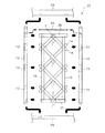
次に以上の構成における連結構造を用いた木造建築物用構造体の全体的構成について説明する。図6は構造体の全体構成を示す正面分解図、図7は同じく組立完成状態を示す木造建築物用構造体の斜視図である。 Next, the overall configuration of the structure for a wooden building using the connection structure in the above configuration will be described. FIG. 6 is a front exploded view showing the overall structure of the structure, and FIG. 7 is a perspective view of the structure for a wooden building, showing the assembled state.
本実施の形態では、図6に示すように、傾斜材1は上下方向で4対配置され、そのうちの中央の2対は各傾斜材1を長尺とし、長手方向中央の交差位置も相欠き連結構造により同一面内に収るようにしてX字形に交差部を構成して、各端部1aが左右の枠材10に前述のごとき構造により接合している。
また上部及び下部の2対は中央の傾斜材1の略半分の長さであって、その両側が前述のごとき構造により、左右の枠材10に接合している。上部側傾斜材1の上端となる交差部7は、左右の枠材10にほぞとほぞ孔結合により連結した横架材としての天枠20の下部中央に連結している。下部側傾斜材1の下端となる交差部7は、左右の枠材10にほぞとほぞ孔結合により連結した地枠21の上部中央に連結している。これら天枠20、地枠21との連結は、上記した枠材10と同様に、矩形状の受入孔を形成して嵌め込むことで行われる。そして、全体として各傾斜材1によりそれぞれが略正方形状の菱形模様が上下に連続する意匠の枠組形状となっている。
In the present embodiment, as shown in FIG. 6, four pairs of
The upper and lower pairs are approximately half the length of the central
これに対し、主体枠22は、下部側の土台23と上部側の横架材24間の両側にほぞとほぞ孔結合により連結した前述した左右一対の柱材12により構成され、前記両枠材10、天枠20及び地枠21により構成された枠組体をその内側に固定している。
なお、横架材24と天枠20との間には本実施の形態では空間が形成され、天枠20の直上に、補強部材25、例えば鋼製シャフトを横設し、両端を左右の柱材12に貫通配置させ、ナット部材等にて締結固定し、左右の柱材12間を連結している。
On the other hand, the
In the present embodiment, a space is formed between the
前記天枠20及び地枠21の柱材12に対する連結構造は、ほぞとほぞ孔で構成される構造にて結合され、左右の枠材10と柱材12とは、前記傾斜材1の枠材10外側への突出端部1aを受ける前述の受入孔13を介して連結される。
The connection structure of the
したがって、以上のように組上げられた構造体は、X字形に組まれた複数の傾斜材1により、横架材24の長手方向に沿う外力である略水平方向の外力によって枠組み全体を菱形状に変形させようとする外力に対する抵抗体として作用し、しかも従来の対角線方向に配置される筋交いなどに比べてその抵抗が大きくなるものである。
これにより、この構造体は、耐力壁として構成することも可能となり、木造建築物用構造体として用いた場合に、木造建築物の強度向上効果が高くなる効果を得られる。
加えて各傾斜材1は相欠き構造により同一面内に収っており、主体枠22の厚さ内にX字形構造が縦方向複数に配列され、しかも外面には釘などの接合部材が露出することがなく、素材自体の表面となるため、それ自体を仕上げ材として活用でき、単なる構造材としてだけでなく、和風意匠のパーティションなどとして単独で使用可能となる。
Therefore, in the structure assembled as described above, the entire frame is rhombus-shaped by the external force in the substantially horizontal direction that is the external force along the longitudinal direction of the
Thereby, this structure can also be configured as a load-bearing wall, and when used as a structure for a wooden building, the effect of improving the strength of the wooden building can be obtained.
In addition, each
また、傾斜体1により、貫通した空間部分を備えた構成となることから、採光を行うことも可能な壁状構造体となり、単なる壁材のような圧迫感を取り除くことが可能となって、屋内空間を広く見せることも可能となる。
さらには、傾斜材1、枠材10などの枠組み状の部材のみで構造体として十分な強度を得られることから、この構造を障子格子のように構成することも可能であり、一方の面に障子紙を配置して構成する、或いは透明ガラスや、すりガラスを嵌め込む、透明樹脂板や着色樹脂板を展設するなど、種々の素材と組合わせて使用可能であり、意匠性を向上することが可能となる。
Moreover, since it becomes the structure provided with the space part penetrated by the
Furthermore, since sufficient strength can be obtained as a structure with only a frame-like member such as the
なお、本実施形態では図7に示すように、柱材12、土台23、横架材24の幅寸法に対し、枠材10、天枠20及び地枠21と同一の幅としたが、これより細幅であって主体枠22の内側に収るようにしても良い。
In this embodiment, as shown in FIG. 7, the width of the
また、前記中央でX字形に交差する部分も相欠き構造として切欠き凹部を形成した。この場合には切欠き凹部の両側または片側に必要に応じて嵌合部の接触面積を減ずるための傾斜面を形成しても良いが、この部分では左右に端部までの長さが十分あり、剪断剥離が生ずるおそれが少ないうえに、外部に露出する箇所なので意匠性などを勘案すれば、必ずしも必要ではない。 Moreover, the part which cross | intersects the X shape in the said center also formed the notch recessed part as a notch structure. In this case, inclined surfaces for reducing the contact area of the fitting portion may be formed on both sides or one side of the notch recess as necessary, but this portion has sufficient length to the left and right ends. In addition, there is little possibility that shear peeling occurs, and it is not always necessary if it is designed to be exposed to the outside because of its design.
1…木材(傾斜材)
1a…端部
1b…当接面
2…切欠き凹部
2a…縁部
3…傾斜部
4…だぼ孔
5…だぼ
7…交差部
10…枠材
10a…半分割体
11…X字形切欠き凹部
12…柱材
13…受入孔
20…枠材(天枠)
21…枠材(地枠)
22…柱主体枠
23…土台
24…横架材
1 ... wood (gradient)
DESCRIPTION OF
21 ... Frame material (ground frame)
22 ... Column
Claims (5)
互いに嵌め合わされる切欠き凹部の木理方向に沿った両縁部の少なくとも一方に傾斜部を形成し、交差する相手側木材の木理直交方向の当接面に対する接触面積を減じたことを特徴とする木材の連結構造。 By forming a notch recess that is half the thickness of each other in the thickness direction and fitting the notch recesses together,
Inclined portions are formed on at least one of both edges along the grain direction of the notched recesses to be fitted to each other, and the contact area with the abutment surface of the intersecting wood in the direction perpendicular to the grain direction is reduced. Connected wood structure.
両端部近傍を前記連結構造とし交差部を形成して複数対で構成するとともに長手方向を傾斜させて配置する木材と、各木材の両側交差部を固定する一対の枠材からなり、
前記各枠材は厚み方向に半分割されるとともに、前記木材の材厚の半分の厚みに相当し、かつ前記交差部の交差形状に応じたX字形の切欠き凹部を形成することにより、前記各交差部を挟み込み、かつ端部を枠材の外部に突出させた状態に固定するものであることを特徴とする木造建築物用構造体。 A structure for a wooden building using the wood connection structure according to claim 1, 2 or 3,
It consists of a pair of frame members that fix both sides of each timber, and a wood that is arranged in a plurality of pairs with the connection structure in the vicinity of both ends to form a plurality of pairs and inclined in the longitudinal direction,
Each of the frame members is divided in half in the thickness direction, and corresponds to half the thickness of the wood, and by forming an X-shaped cutout recess corresponding to the intersection shape of the intersection portion, A structure for a wooden building, characterized in that each crossing portion is sandwiched and the end portion is fixed to a state protruding from the frame material.
Priority Applications (1)
| Application Number | Priority Date | Filing Date | Title |
|---|---|---|---|
| JP2005188487A JP4034322B2 (en) | 2005-06-28 | 2005-06-28 | Connection structure of wood and structure for wooden building using the same |
Applications Claiming Priority (1)
| Application Number | Priority Date | Filing Date | Title |
|---|---|---|---|
| JP2005188487A JP4034322B2 (en) | 2005-06-28 | 2005-06-28 | Connection structure of wood and structure for wooden building using the same |
Publications (2)
| Publication Number | Publication Date |
|---|---|
| JP2007009437A JP2007009437A (en) | 2007-01-18 |
| JP4034322B2 true JP4034322B2 (en) | 2008-01-16 |
Family
ID=37748293
Family Applications (1)
| Application Number | Title | Priority Date | Filing Date |
|---|---|---|---|
| JP2005188487A Active JP4034322B2 (en) | 2005-06-28 | 2005-06-28 | Connection structure of wood and structure for wooden building using the same |
Country Status (1)
| Country | Link |
|---|---|
| JP (1) | JP4034322B2 (en) |
Families Citing this family (2)
| Publication number | Priority date | Publication date | Assignee | Title |
|---|---|---|---|---|
| DE4032411A1 (en) * | 1990-10-12 | 1992-04-16 | Daimler Benz Ag | METHOD FOR PRODUCING T-GATE ELECTRODES |
| JP6999145B1 (en) | 2021-07-21 | 2022-01-18 | 株式会社ホルツストラ一級建築士事務所 | Manufacturing method of bearing wall and bearing wall |
-
2005
- 2005-06-28 JP JP2005188487A patent/JP4034322B2/en active Active
Also Published As
| Publication number | Publication date |
|---|---|
| JP2007009437A (en) | 2007-01-18 |
Similar Documents
| Publication | Publication Date | Title |
|---|---|---|
| JP6202465B2 (en) | Joint structure of wood members | |
| JP4095946B2 (en) | Joint structure of wood members | |
| KR101677007B1 (en) | Jointing structure of wood | |
| JP4034322B2 (en) | Connection structure of wood and structure for wooden building using the same | |
| JP2017040141A (en) | Wall panel of wooden building | |
| JP6241097B2 (en) | Wood structure member, joining structure of wood structure member and construction method thereof | |
| JP5702345B2 (en) | Connecting wood fittings for construction | |
| JP2004263548A (en) | Connection structure between timbers in wooden building, and method of connecting the same | |
| JP6089241B2 (en) | Reinforcing member of wood joint and wood joint structure | |
| JP3742369B2 (en) | Beam connection structure | |
| WO2021245735A1 (en) | Laminated wood joint structure | |
| JP3149100U (en) | Hole down hardware | |
| JP6414261B2 (en) | Wood ramen moment resistance structure | |
| JP5749663B2 (en) | Column structure | |
| JP6388177B1 (en) | Wooden beam end joint hardware and wooden beam end joint structure using this wooden beam end joint hardware | |
| JP2003328437A (en) | Connecting structure for gluelam | |
| JP2014214497A (en) | Wooden beam joint structure and wooden beam joint method | |
| JP3671163B2 (en) | house | |
| JP4050277B2 (en) | Wall materials and wooden building structures using them | |
| JP2022155827A (en) | Junction structure between metal column and wooden member | |
| JP3538151B2 (en) | Frame structure, frame structure | |
| JP4264895B2 (en) | Structure of plate wall in wooden frame | |
| JP4001519B2 (en) | Joining structure and joining method | |
| JP2000017730A (en) | Connecting fitting | |
| JP2024035049A (en) | Joint structure between horizontal members |
Legal Events
| Date | Code | Title | Description |
|---|---|---|---|
| A977 | Report on retrieval |
Free format text: JAPANESE INTERMEDIATE CODE: A971007 Effective date: 20070426 |
|
| A131 | Notification of reasons for refusal |
Free format text: JAPANESE INTERMEDIATE CODE: A131 Effective date: 20070807 |
|
| A521 | Request for written amendment filed |
Free format text: JAPANESE INTERMEDIATE CODE: A523 Effective date: 20070821 |
|
| TRDD | Decision of grant or rejection written | ||
| A01 | Written decision to grant a patent or to grant a registration (utility model) |
Free format text: JAPANESE INTERMEDIATE CODE: A01 Effective date: 20070925 |
|
| A61 | First payment of annual fees (during grant procedure) |
Free format text: JAPANESE INTERMEDIATE CODE: A61 Effective date: 20071024 |
|
| FPAY | Renewal fee payment (event date is renewal date of database) |
Free format text: PAYMENT UNTIL: 20101102 Year of fee payment: 3 |
|
| R150 | Certificate of patent or registration of utility model |
Ref document number: 4034322 Country of ref document: JP Free format text: JAPANESE INTERMEDIATE CODE: R150 Free format text: JAPANESE INTERMEDIATE CODE: R150 |
|
| FPAY | Renewal fee payment (event date is renewal date of database) |
Free format text: PAYMENT UNTIL: 20101102 Year of fee payment: 3 |
|
| FPAY | Renewal fee payment (event date is renewal date of database) |
Free format text: PAYMENT UNTIL: 20131102 Year of fee payment: 6 |
|
| R250 | Receipt of annual fees |
Free format text: JAPANESE INTERMEDIATE CODE: R250 |
|
| R250 | Receipt of annual fees |
Free format text: JAPANESE INTERMEDIATE CODE: R250 |
|
| R250 | Receipt of annual fees |
Free format text: JAPANESE INTERMEDIATE CODE: R250 |
|
| R250 | Receipt of annual fees |
Free format text: JAPANESE INTERMEDIATE CODE: R250 |
|
| R250 | Receipt of annual fees |
Free format text: JAPANESE INTERMEDIATE CODE: R250 |