JP4032365B2 - Railway vehicle vibration control system - Google Patents
Railway vehicle vibration control system Download PDFInfo
- Publication number
- JP4032365B2 JP4032365B2 JP12092496A JP12092496A JP4032365B2 JP 4032365 B2 JP4032365 B2 JP 4032365B2 JP 12092496 A JP12092496 A JP 12092496A JP 12092496 A JP12092496 A JP 12092496A JP 4032365 B2 JP4032365 B2 JP 4032365B2
- Authority
- JP
- Japan
- Prior art keywords
- vehicle body
- absolute lateral
- absolute
- damping force
- carriage
- Prior art date
- Legal status (The legal status is an assumption and is not a legal conclusion. Google has not performed a legal analysis and makes no representation as to the accuracy of the status listed.)
- Expired - Fee Related
Links
Images


Landscapes
- Vehicle Body Suspensions (AREA)
- Vibration Prevention Devices (AREA)
Description
【0001】
【発明の属する技術分野】
本発明は、鉄道車両用振動制御装置に関する。
【0002】
【従来の技術】
鉄道車両では揺れを抑え、快適な乗り心地を確保することが望まれており、この要望に応えるために振動制御装置が用いられている。このような振動制御装置を用いた鉄道車両の一例を図10に示す。
【0003】
この鉄道車両1は、モノレール2を用いて走行されるようになっている。図において、鉄道車両1は、タイヤ3を介してモノレール2に案内される、前(図10紙面裏面側)、後(図10紙面表面側)、2台の台車4F ,4R と、前、後台車4F ,4R に金属スプリングまたはエアスプリング等のばね部材5を介して上下方向及び水平方向に揺動可能に支持される車体6と、前、後台車4F ,4R と車体6との間に、車体6の前、後台車4F ,4R に対する左右方向の移動に対して減衰力を発生するようにそれぞれ介装された減衰力可変型の前、後側のダンパ7F ,7R と、前、後台車4F ,4R に対応して車体6の底部にそれぞれ設けられて車体6の絶対横加速度を検出する前側、後側底部絶対横加速度センサ8FU,8RUと、前側、後側底部絶対横加速度センサ8FU,8RUの検出データに基づいて前、後側のダンパ7F ,7R の減衰力を調整するコントローラ9とから大略構成されている。
【0004】
この鉄道車両1では、前側、後側底部絶対横加速度センサ8FU,8RUが検出した絶対横加速度データから前側、後側横速度を求め、コントローラ9がここで求めた前側、後側それぞれの速度データに応じて前、後側のダンパ7F ,7R の減衰力を調整し、横方向の揺れを抑え、快適な乗り心地を確保するようにしている。
【発明が解決しようとする課題】
【0005】
しかし、この従来技術では、後述するようにレールの軌道狂い等により車体に作用する複雑なロール速度成分等を考慮せずに、このロール速度成分等をも含めて絶対横加速度として検出し減衰力調整を行うため、台車の鉛直線上にある台車上部車体重心(後述する水平軸(X)と台車の鉛直線との交点。請求項1,2の台車上部車体重心に相当する。)における車体の純粋な絶対横速度(車体6の左右方向推移に伴う絶対横速度)に基づいた減衰力調整を行えず、乗員が略位置する台車上部車体重心高さ位置における振動抑制制御が良好なものになっていないというのが実情であった。すなわち、鉄道車両1において、実際には、車体6領域内の進行方向の水平軸(X)を中心とする回動(以下、自転運動という。)、車体6上方の水平軸(U)を中心とする回動(以下、上中心ロール運動という。)、車体6下方の水平軸(L)を中心とする回動(以下、下中心ロール運動)が発生する。そして、前側、後側底部絶対横加速度センサ8FL,8RLは、前記純粋な絶対横速度のみならず、自転運動、上中心ロール運動および下中心ロール運動による横方向速度成分を含めて検出してしまうという問題点があった。
【0006】
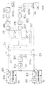
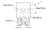
そこで、上中心ロール運動および下中心ロール運動による横方向速度成分を検出し、各速度成分に対応した振動制御を行うために、例えば図11に示すように、前、後台車4F ,4R に対応して車体6の左右にそれぞれ、上下方向の加速度を検出する4つ(前左、前右、後左、後右側)の上下方向加速度センサ10FS,10FR,10RS,10RRを付加することや、ロール角を検出するセンサ(ジャイロセンサ)を設けることが考えられる。
【0007】
しかしながら、上述したように4つ(前左、前右、後左、後右側)の上下方向加速度センサ10FS,10FR,10RS,10RRを付加することは、部品数の増加となり、信頼性低下、保守性低下を招きやすく望ましくなかった。また、ジャイロセンサを設けることについては、ジャイロセンサが精密な機構を要求されて高価なものとなっており、コストアップを抑制する上で望ましくなかった。
【0008】
本発明は、上記事情に鑑みてなされたもので、自転運動及び上、下中心ロール運動からそれぞれの運動により発生する横方向絶対速度成分を検出して、前記台車上部車体重心における純粋な絶対横速度を求めることにより、良好な振動抑制制御を行える鉄道車両用振動制御装置を提供することにある。
また、簡易な構成で、自転運動及び上、下中心ロール運動からそれぞれの運動により発生する横方向絶対速度成分を分離、検出できる鉄道車両用振動制御装置を提供することにある。
【0009】
【課題を解決するための手段】
請求項1記載に係る鉄道車両用振動制御装置の発明は、車体の前後それぞれに設けられた前後一対の台車と、前記車体と前記一対の台車との間に設けられ、車体の台車に対する左右方向の移動に対して減衰力を発生し、縮み側の減衰力が小さい値のとき、伸び側の減衰力を大きい値とし、伸び側の減衰力が小さい値のとき、縮み側の減衰力を大きい値とする減衰力可変型ダンパと、前記各台車の鉛直線と前記車体の上方の水平軸との各交点を中心とする上中心ロール速度成分および前記各台車の鉛直線と前記車体の下方の水平軸との各交点を中心とする下中心ロール速度成分を除いた値として、前記各台車の鉛直線と車体重心を含む水平軸との各交点に相当する台車上部車体重心における車体の絶対横速度を検出する絶対横速度検出手段と、該絶対横速度検出手段の検出結果に基づいて、前記車体が左右方向一側へ移動しているときに前記車体が前記台車に対する一側への相対移動に対して減衰力を大きい値とするように調整するコントローラと、を備えたことを特徴とする。
【0010】
請求項2記載に係る鉄道車両用振動制御装置の発明は、請求項1に記載の鉄道車両用振動制御装置において、絶対横速度検出手段は、前後一対の台車にそれぞれ対応して車体の底部に設けられ、該車体の底部における左右方向の絶対横速度を検出する底部絶対横速度検出手段と、前後一対の台車にそれぞれ対応して車体の上部に設けられ、該車体の上部における左右方向の絶対横速度を検出する上部絶対横速度検出手段とを有し、さらに、前記底部絶対横速度検出手段および前記上部絶対横速度検出手段の検出結果から、前記台車上部車体重心を中心とする車体の自転速度成分、前記上中心ロール速度成分および前記下中心ロール速度成分を求め、この各速度成分を前記底部絶対横速度検出手段または前記上部絶対横速度検出手段のいずれか一方の検出結果から除いた値を前記絶対横速度とするようにしたことを特徴とする。
【0011】
【発明の実施の形態】
以下、本発明の一実施の形態の鉄道車両用振動制御装置を図1ないし図8に基づいて説明する。なお、図10、図11に示す部分、部材と同等の部分、部材についての図示、記載は適宜省略する。
【0012】
図1、図2において、鉄道車両1は、車輪11を介して2本のレール12に案内される、前(図1紙面裏面側)、後(図1紙面表面側)一対の台車4F ,4R と、この前、後台車4F ,4R にばね部材5を介して上下方向及び水平方向に揺動可能に支持される車体6と、前、後台車4F ,4R と車体6との間に、車体6の前、後台車4F ,4R に対する左右方向の移動に対して減衰力を発生するようにそれぞれ介装された減衰力可変型の前、後側のセミアクティブダンパ(以下、減衰力可変型ダンパという。)7F ,7R と、前、後台車4F ,4R に対応して車体6の底部にそれぞれ設けられて車体6の底部における絶対横加速度を検出する前側、後側の底部絶対横加速度センサ(底部絶対横速度検出手段)8FL,8RLと、前、後台車4F ,4R に対応して車体6の上部にそれぞれ設けられて車体6の上部における絶対横加速度を検出する前側、後側の上部絶対横加速度センサ(上部絶対横速度検出手段)8FU,8RUと、底部絶対横加速度センサ8FL,8RLの検出データ及び上部絶対横加速度センサ8FU,8RUの検出データに基づいて減衰力可変型ダンパ7F ,7R の減衰力を調整するコントローラ9とから大略構成されている。
【0013】
ここで、本発明では、底部絶対横加速度センサ8FL,8RLの検出データに対応する前側、後側の底部絶対横速度(後述するブロックB12で得られる。)と、上部絶対横加速度センサ8FU,8RUの検出データに対応する前側、後側の上部絶対横速度(後述するブロックB10で得られる。)とに基づいて、車体6の前側、後側における前記自転運動、上中心ロール運動、下中心ロール運動が検出され、この各運動により検出された各速度成分を、前記前側、後側の底部絶対横速度または前記前側、後側の上部絶対横速度のいずれか一方から除いた値を前述の台車上部車体重心(後述する水平軸(X)と台車の鉛直線との交点)における車体の純粋な絶対横速度(車体6の左右方向推移に伴う絶対横速度)としている。つぎに上記各速度成分の検出方法について、車体6の前側を対象にし(すなわち、前側の底部絶対横加速度センサ8FLの検出データに対応する前側底部横速度Vl と、前側の上部絶対横加速度センサ8FUの検出データに対応する前側上部横速度Vu とを用い)、図1を参照して以下に説明する。
【0014】
前側底部横速度(前側の底部絶対横加速度センサ8FLの検出データαl に対応する。)Vl 、前側上部横速度(前側の上部絶対横加速度センサ8FUの検出データαu に対応する。)Vu は式1、式2で求められる。以下、前側底部横速度Vl 、前側上部横速度Vu を簡略して、適宜、底部横速度Vl 、上部横速度Vu という。
【0015】
Vu =Vg +ωl (rl +2h)+ωu ru −ω0 h (式1)
Vl =Vg +ωl rl +ωu (ru +2h)+ω0 h (式2)
ここで、 Vg :車体6の台車上部車体重心における絶対横速度(純粋絶対横速度)
ωu :車体6上方の水平軸U回りのモーメント
ωl :車体6下方の水平軸L回りのモーメント
ω0 :車体6領域内の進行方向の水平軸X回りのモーメント
ru :水平軸Uから前側上部絶対横加速度センサ8FUまでの距離
rl :水平軸Lから前側底部絶対横加速度センサ8FLまでの距離
h :水平軸Xから前側上部絶対横加速度センサ8FUまでの距離(=軸Iから前側底部絶対横加速度センサ8FLまでの距離)を表しており、ru ,rl およびhは各種車体に応じて設定される定数である。
【0016】
前記台車上部車体重心(図1上水平軸Xと一致)を中心とする車体6の自転運動による速度成分(以下、自転速度成分という。)を除いた上部横速度Vu ′および底部横速度Vl ′は式3、式4で求められる。
【0017】
Vu ′=Vu +ω0 h=Vg +ωl (rl +2h)+ωu ru (式3)
Vl ′=Vl −ω0 h=Vg +ωl rl +ωu (ru +2h) (式4)
【0018】
ここで、水平軸Uを中心とする上中心ロール運動による速度成分(以下、上中心ロール速度成分という。)と下中心ロール運動による速度成分(以下、下中心ロール速度成分という。)は同時に得られないとすると、上中心ロール運動が発生する時(|Vu ′|<|Vl ′|)の自転速度成分を除いた上部横速度Vu ′、底部横速度Vl ′は、式5、式6で求められる。
【0019】
Vu ′=Vg +ωu ru (式5)
Vl ′=Vg +ωu (ru +2h) (式6)
【0020】
そして、水平軸U回りのモーメントωu と車体6の純粋絶対横速度Vg は、式7、式8のようになる。
【0021】
ωu =(Vl ′−Vu ′)/(2h) (式7)
Vg =Vl ′−(Vl ′−Vu ′)(ru +2h)/(2h) (式8)
【0022】
ここで、自転運動のみ(ロール運動は同時に発生しないとしたとき)の水平軸X回りのモーメント(角速度)ω0 は、次式で示される。
【0023】
ω0 =Vl −Vu (式8A)
【0024】
この式8Aを式3、式4に代入してVl ′、Vu ′をVl 、Vu で表現し、このVl ′、Vu ′の式を、式7、式8に代入することで、ωu 、Vg は式7a,式8aのようにVl ,Vu で示されることになる。すなわち、Vl ,Vu からωu 、Vg が得られることになる。
【0025】
ωu =(1−2h)(Vl −Vu )/(2h) (式7a)
Vg ={(1−h)Vl +Vu h}−(1−2h)(Vl −Vu )(ru +2h)/(2h) (式8a)
【0026】
同様に、下中心ロール運動が発生する時(|Vu ′|>|Vl ′|)の水平軸L回りのモーメントωl と車体6の純粋絶対横速度Vg は、前記式3、式4にωu =0を代入して得られる式に基づいて求められ、式9、式10のようになる。
【0027】
ωl =−(Vl ′−Vu ′)/(2h) (式9)
Vg =Vl ′+(Vl ′−Vu ′)rl /(2h) (式10)
【0028】
上記ωl ,Vg の式は、式9a、式10aのようにVl 、Vu で示される。すなわち、Vl ,Vu からωu 、Vg が得られることになる。
【0029】
ωl =−(1−2h)(Vl −Vu )/(2h) (式9a)
Vg ={(1−h)Vl +Vu h}+(1−2h)(Vl −Vu )(rl )/(2h) (式10a)
よって、前側の上部絶対横加速度センサ8FU及び底部絶対横加速度センサ8FLの検出データに基づいて自転速度成分、上中心ロール速度成分、下中心ロール速度成分を検出することができ、ひいては車体6の台車上部車体重心における純粋な絶対横速度を求めることができる。
【0030】
前記前、後台車4F ,4R の進行方向に対して右側(図1右側)には、前、後側の台車側ブラケット13F ,13R がそれぞれ取り付けられている。前、後側の台車側ブラケット13F ,13R に対向するように車体6の進行方向左側部分には、前、後側の車体側ブラケット14F ,14R が取り付けられている。
【0031】
前側の台車側ブラケット13F と前側の車体側ブラケット14F との間、後側の台車側ブラケット13R と後側の車体側ブラケット14R との間に、車体6の前、後台車4F ,4R に対する左右方向の移動に対して減衰力を発生する前記前、後側の減衰力可変型ダンパ7F ,7R がそれぞれ介装されている。ここで、前、後側の減衰力可変型ダンパ7F ,7R は、図3に示すように、油液が封入された筒状のダンパ本体15と、ダンパ本体15内に変位可能に収納されたピストン(図示省略)と、ピストンに固定され一端部がダンパ本体15から突出するシャフト17と、ピストンを含むダンパ本体15内に設けられ、油液流路(図示省略)の調整により減衰力を発生する減衰力発生機構(図示省略)と、この減衰力発生機構を作動して減衰力を調整するバルブ機構18と、後述する目標減衰係数Cに応じてバルブ機構18を駆動する比例ソレノイド19とからなっている。
【0032】
そして、この場合、前、後側の車体側ブラケット14F ,14R にダンパ本体15が保持され、前、後側の台車側ブラケット13F ,13R にシャフト17の一端側(ダンパ本体15の外側部分)が保持されており、車体6の進行方向に対して左右方向の運動を規制するようになっている。
【0033】
前、後側の減衰力可変型ダンパ7F ,7R は、図4、図5に示す減衰力特性を有している。ここで、図4は、比例ソレノイド19に供給される電流Iに対するピストンスピードが10cm/s のときの減衰力を示したものである。前、後側の減衰力可変型ダンパ7F ,7R は、通常電流I2 では減衰力は、伸び側、縮み側共に小さい値(ソフト)になっている。ここで、減衰力可変型ダンパ7F ,7R は、車体6が前、後台車4F ,4R に対して相対的に左方へ移動したときに伸び、右方へ移動したときに縮むようになっている。そして、電流IをI2 からI1 へと小さくすると、減衰力特性は、縮み側減衰力を小さい(ソフト)状態で伸び側の減衰力が大きく(ハードに)なる。これに対して、電流IをI2 からI3 へと大きくしていくと、伸び側減衰力を小さい(ソフト)状態で縮み側の減衰力が大きく(ハードに)なる。
【0034】
また、図5は、ピストンのスピードに対する減衰力を示している。電流IがI1 からI2 の間では、縮み側は、実線21に示すように略一定値の状態で伸び側が実線22から実線23の間の減衰力を得ることになる。また、電流がI2 からI3 の間では、伸び側減衰力は実線23に示すように略一定の状態で、縮み側減衰力が実線21から実線24の間で可変になる。
【0035】
前側、後側の底部絶対横加速度センサ8FL,8RL、前側、後側の上部絶対横加速度センサ8FU,8RU及び前、後側の減衰力可変型ダンパ7F ,7R の各比例ソレノイド19に接続してコントローラ9が車体6に設けられている。
【0036】
コントローラ9は、図6に示すように電力供給を受ける(ステップS1)と、まず初期設定を行なって(ステップS2)制御周期に達したか否かを判定する(ステップS3)。ステップS3では、制御周期に達したと判定するまで繰り返して制御周期に達したか否かを判定する。
【0037】
ステップS3で制御周期に達したと判定すると、前制御周期の目標電流(目標減衰係数)に基づいて比例ソレノイド19(アクチュエータ)を駆動し、目標減衰力に対応した減衰力を得る(ステップS4)。続いてステップS5で比例ソレノイド19以外の機器(例えばLED)に信号を出力して制御する。次に前上部、前底部、後上部、後底部絶対横加速度センサ8FU,8FL,8RU,8RLから絶対横加速度信号(前上部、前底部、後上部、後底部絶対横加速度信号)αを読み込む(ステップS6)。続いて各絶対横加速度信号αに基づいて後述する演算処理を行って、目標減衰係数Cを求め、これに対応する目標電流Iの決定を行い(ステップS7)、次の制御周期のステップS4で目標電流Iに基づいて比例ソレノイド19を駆動して所望の減衰力を得る。
【0038】
ここで、上記ステップS7の演算処理内容を説明する。コントローラ9はステップS7において、図7に示すように前側の底部絶対横加速度センサ8FLからの前側底部絶対横加速度αl 、前側の上部絶対横加速度センサ8FUからの前側上部絶対横加速度αu に基づいて、ブロックB10〜B25の演算処理を行うと共に、後側の底部絶対横加速度センサ8RL、後側の上部絶対横加速度センサ8RUの後側底部、後側上部絶対横加速度データに基づいて、ブロックB10〜B25と同等の演算処理(図示省略)を行う。ここでは、前側を対象として説明する。
【0039】
図7において、ブロックB10〜B25で前側台車の台車上部車体重心における純粋絶対横速度Vg を求めている。
ブロックB10〜B25aにおいて、まず前側の上部絶対横加速度センサ8FUで検出された上部絶対横加速度αu はブロックB10で積分処理され、これにより前側上部横速度Vu が得られ、この前側上部横速度Vu がブロックB11でハイパスフィルタ処理されてブロックB10の積分誤差を除去して前側上部横速度Vu を求める。同様にして、底部絶対横加速度センサ8FLで検出された底部絶対横加速度αl に対してブロックB12、B13の処理が行われ、底部横速度Vl が求められる。
【0040】
次に、差分回路D1で底部横速度Vl と上部横速度Vu との差分演算(Vl −Vu )を行って自転速度成分ω0 を求め、ブロックB14で自転速度成分用ゲインKi を乗算し、ブロックB15でローパスフィルタをかけ、さらに、ブロックB15aで高さhを乗算してデータω0 hを得、加え合わせ回路D2、差分回路D3でそれぞれ、Vu +ω0 h、Vu −ω0 hの演算を行って、自転速度成分を除いた底部横速度Vl ′(=Vu +ω0 h)、上部横速度Vu ′(=Vu −ω0 h)を求める。続く差分回路D4で「Vl ′−Vu ′」の演算が行われる。
【0041】
ブロックB16〜B18では、前記自転速度成分を除いた底部横速度Vl ′、自転速度成分を除いた上部横速度Vu ′から、前記式7に準じて水平軸U回りのモーメントωu を求め、ブロックB19で上中心ロール速度成分用ゲインKu を乗算し、ブロックB20でローパスフィルタをかけ、上中心ロール運動成分により算出された横速度を求め、さらにブロック20aで前記式8に準じて「ru +2h」を乗算し、得られたデータを差分回路D6に出力する。また、ブロックB21〜B23では、前記自転速度成分を除いた底部横速度Vl ′および上部横速度Vu ′から、前記式9に準じて水平軸L回りのモーメントωl を求め、ブロックB24で下中心ロール速度成分用ゲインKl を乗算し、ブロックB25でローパスフィルタをかけ、下中心ロール運動成分により算出された横速度を求め、さらにブロック25aで「rl 」を乗算し、得られたデータを差分回路D5に出力する。
【0042】
次に、差分回路D5,D6で自転速度成分を除いた底部横速度Vl ′から、ブロック25aの出力データ、ブロック20aの出力データを減算して純粋前側絶対横速度Vg を求める。(よって、この図7は本発明の絶対横速度検出手段を構成している。)なお、ここでは、底部横速度Vl ′からブロックB25aの出力データ、ブロックB20aの出力データを減算しているが、上部横速度Vu ′から上記各データを減算して純粋絶対横速度Vg (前側)を求めてもよいものである。
【0043】
上述した前側の信号処理と同様に後側の信号処理が行われ、純粋絶対横速度Vg (後側)が求められ、その後、純粋絶対横速度Vg (前側)および純粋絶対横速度Vg (後側)は、図8に示す処理が行われる。すなわち、純粋絶対横速度Vg (前側)は、ブロックB38において、前、後側独立である前側ゲインが乗算され、ブロックB39でローパスフィルタがかけられ、加え合わせ回路D7に出力される。一方、純粋絶対横速度Vg (後側)も同様に、ブロックB40において、前、後側独立である後側ゲインが乗算され、ブロックB41でローパスフィルタがかけられ、加え合わせ回路D9に出力される。
【0044】
また、純粋絶対横速度Vg (前側)および純粋絶対横速度Vg (後側)は、それぞれ差分回路D11および加え合わせ回路D12に出力される。そして、差分回路D11の差分演算処理によって車体6のヨー速度成分と、加え合わせ回路D12の加え合わせ演算処理によって車体6のスエー速度成分とがそれぞれ求められる。求められたヨー速度成分に対しては、ブロックB33でヨー速度成分用ゲインを乗算し、ブロックB34でローパスフィルタをかけ、ここで得たデータは加え合わせ回路D8および差分回路D10に出力される。一方、スエー速度成分に対しては、ブロックB31でスエー速度成分用ゲインを乗算し、ブロックB32でローパスフィルタをかけ、ここで得たデータは加え合わせ回路D7,D9に出力される。
【0045】
そして、加え合わせ回路D7で得た純粋絶対横速度Vg (前側)とスエー速度成分とを加えた速度成分データは、加え合わせ回路D8でさらにヨー速度成分が加えられ、ブロックB36で目標減衰係数C(前側)と、この目標減衰係数Cに対応した比例ソレノイド19に供給される目標電流I(前側)が求められる。
一方、加え合わせ回路D9で得た純粋絶対横速度Vg (後側)とスエー速度成分とを加えた速度成分データは、差分回路D11でヨー速度成分が減算され、ブロックB37で目標減衰係数C(後側)と、この目標減衰係数Cに対応した比例ソレノイド19に供給される目標電流I(後側)が求められる。
ここで求められた前、後側それぞれの目標電流Iを前、後側それぞれの減衰力可変型ダンパ7F ,7R の比例ソレノイド19に出力することにより、減衰力を調整する。
【0046】
以上のようにして、図6のステップS7の処理を終了する。ステップS7の処理を終了すると、ステップS3に戻って上述したように処理が行われる。
【0047】
上記実施の形態では、上中心ロール運動と下中心ロール運動が同時に発生しないとしており、上中心ロール運動と下中心ロール運動が切り替わる時に急激に制御力が変化しないようにブロックB16、B21において、Vの値が徐々に変化するようにしている。なお、急激に変化させるようにしてもよい。この場合、応答性は良くなるが、切換え時の衝撃が発生しやすくなる。
【0048】
上述したように構成した鉄道車両用振動制御装置では、上部、底部絶対横加速度センサ8FU,8FL及びコントローラ9の積分処理ブロックB10,B12が得る上部、底部絶対横速度Vu ,Vl に基づいて、自転速度成分、上中心ロール速度成分、下中心ロール速度成分を求め、その各速度成分を考慮して、台車上部車体重心における純粋絶対横速度(車体6の左右方向推移に伴う絶対横速度)を検出し、この純粋絶対横速度に基づいて比例ソレノイド19を制御して前側、後側のダンパ7F ,7R の減衰力を調整するので、車体6の横運動の低減を確実に果たすことができる。
また、図11に示す従来技術では、ロール運動の抑制を行うために前、後側計6個のセンサが必要とされるが、これに比して本実施の形態では、良好なロール制御を前、後側計4個のセンサで行えるので、接続線が少なくて済む上、信号処理量も少なくなって装置の構成を簡略化できる。
【0049】
なお、上記実施の形態では、図8のブロック図に示すようにスエー運動による成分、ヨー運動による成分を分離して制御するようにしているので、このスエー成分、ヨー成分算出結果に応じて前、後側の減衰力可変型ダンパ7F ,7R の減衰力が調整され、ヨー運動の低減を図ることができると共に、横方向の車体の推移(スエー運動)の低減を図ることができ、さらに精度よく車体の振動抑制制御を行うことができる。
【0050】
また、上記実施の形態では、2本のレール12上を走行するタイプの鉄道車両1を例にしたが、これに代えて図9に示すようにモノレールタイプの鉄道車両1に本発明の鉄道車両用振動制御装置を適用してもよい。なお、図9に示す鉄道車両1は、図1に示すものに比して、2本のレール12に代えてコンクリートの軌道からなるモノレール2を設け、車輪11に代えてタイヤ3を介して前、後台車4F ,4R をモノレール2に支持させることが異なっている。
【0051】
【発明の効果】
本発明は、各台車の鉛直線と車体重心を含む水平軸との各交点に相当する台車上部車体重心における車体の絶対横速度を検出し、車体と各台車との間に設けられた減衰力可変型ダンパを制御するようにしたので、乗員が略位置する台車上部車体重心高さ位置における振動を効果的に抑制することができるので、乗り心地の向上を図ることができる。さらに、車体の振動要素(速度成分)として、自転速度成分、上中心ロール速度成分および下中心ロール速度成分の台車上部車体重心における絶対横速度を、車体の底部及び上部の各台車に対応する部分に設けた底部、上部絶対横速度検出手段により求め、この各速度成分を底部または上部絶対横速度検出手段の検出結果から除くことで、車体の純粋な絶対横速度を求めるようにしているので、底部絶対横速度検出手段と上部絶対横速度検出手段のみで、純粋な絶対横速度を得ることができ、簡易な装置構成とすることができる。
【図面の簡単な説明】
【図1】本発明の一実施の形態の鉄道車両用振動制御装置を模式的に示す図である。
【図2】同鉄道車両用振動制御装置を用いる鉄道車両を模式的に示す側面図である。
【図3】図1の鉄道車両用振動制御装置のダンパを模式的に示す図である。
【図4】同ダンパの比例ソレノイド供給電流−減衰力特性を示す図である。
【図5】同ダンパのピストンのスピード−減衰力特性を示す図である。
【図6】同鉄道車両用振動制御装置のコントローラの制御内容を示すフローチャートである。
【図7】同コントローラのステップS7の処理内容を模式的に示すブロック線図である。
【図8】同コントローラのステップS7の処理内容を模式的に示すブロック線図である。
【図9】図1の鉄道車両に代えるモノレールタイプの鉄道車両の一例を示す図である。
【図10】従来技術の一例を模式的に示す図である。
【図11】従来技術の他の例を模式的に示す図である。
【符号の説明】
4F ,4R 前、後台車
6 車体
7F ,7R 前、後側の減衰力可変型ダンパ
8FU,8FL,8RU,8RL 前上部、前底部、後上部、後底部絶対横加速度センサ
9 コントローラ[0001]
BACKGROUND OF THE INVENTION
The present invention relates to a railway vehicle vibration control apparatus.
[0002]
[Prior art]
In railway vehicles, it is desired to suppress shaking and to ensure a comfortable ride, and a vibration control device is used to meet this demand. An example of a railway vehicle using such a vibration control device is shown in FIG.
[0003]
The
[0004]
In this
[Problems to be solved by the invention]
[0005]
However, in this prior art, as described later, without taking into account the complicated roll speed component acting on the vehicle body due to a rail trajectory deviation or the like, the absolute lateral acceleration including this roll speed component etc. is detected and the damping force To make adjustments, the center of gravity of the upper body of the carriage on the vertical line of the carriage (the intersection of the horizontal axis (X) described later and the vertical line of the carriage). This corresponds to the center of gravity of the upper body of the carriage of
[0006]
Therefore, in order to detect the lateral speed component due to the upper center roll motion and the lower center roll motion and perform vibration control corresponding to each speed component, for example, as shown in FIG.F , 4R Corresponding to the four vertical acceleration sensors 10 (front left, front right, rear left, rear right) that detect vertical acceleration on the left and right sides of the
[0007]
HoweverHowever, the four vertical acceleration sensors 10 (front left, front right, rear left, rear right) as described above.FS, 10FR, 10RS, 10RRAdding an increase in the number of parts is undesirable because it tends to cause a decrease in reliability and maintainability. Further, providing the gyro sensor is expensive because the gyro sensor is required to have a precise mechanism and is expensive, which is not desirable for suppressing an increase in cost.
[0008]
The present invention has been made in view of the above circumstances.And then rotateThe transverse absolute velocity component generated by each movement from the movement and the upper and lower center roll movementsDetectAn object of the present invention is to provide a railroad vehicle vibration control apparatus that can perform excellent vibration suppression control by obtaining a pure absolute lateral velocity at the center of gravity of the upper body of the carriage.
It is another object of the present invention to provide a railway vehicle vibration control device capable of separating and detecting a lateral absolute velocity component generated by each movement from the rotation movement and the upper and lower center roll movements with a simple configuration.
[0009]
[Means for Solving the Problems]
According to a first aspect of the present invention, there is provided a railcar vibration control device according to a first aspect of the present invention, comprising a pair of front and rear carriages provided on the front and rear sides of the vehicle body, and the vehicle body and the pair of carriages. When the damping force on the contraction side is small, the damping force on the expansion side is set to a large value, and when the damping force on the expansion side is small, the damping force on the contraction side is large. A damping force variable damper with a value,An upper center roll speed component centered at each intersection between the vertical line of each carriage and the horizontal axis above the vehicle body, and each intersection between the vertical line of each carriage and the horizontal axis below the vehicle body. As a value excluding the lower center roll speed component,Absolute lateral speed detecting means for detecting the absolute lateral speed of the vehicle body at the center of gravity of the upper car body corresponding to the intersection of the vertical line of each carriage and the horizontal axis including the center of gravity of the car body, and the detection result of the absolute lateral speed detecting means And a controller for adjusting the damping force to a large value with respect to relative movement to the one side relative to the carriage when the vehicle body is moving to the one side in the left-right direction. It is characterized by.
[0010]
In claim 2The railway vehicle vibration control device according to
[0011]
DETAILED DESCRIPTION OF THE INVENTION
A railcar vibration control apparatus according to an embodiment of the present invention will be described below with reference to FIGS. In addition, the illustration and description about the part and member equivalent to the part and member shown to FIG. 10, FIG. 11 are abbreviate | omitted suitably.
[0012]
1 and 2, a
[0013]
In the present invention, the bottom absolute lateral acceleration sensor 8FL, 8RLThe absolute absolute lateral velocity on the front and rear sides corresponding to the detected data (obtained in block B12 described later) and the upper absolute lateral acceleration sensor 8FU, 8RUBased on the front and rear upper absolute lateral velocities corresponding to the detected data (obtained in block B10 to be described later), the rotational motion, upper center roll motion, and lower center roll on the front side and rear side of the
[0014]
Front bottom lateral velocity (front bottom absolute lateral acceleration sensor 8FLDetection data αl Corresponding to ) Vl , Front upper lateral velocity (front upper absolute lateral acceleration sensor 8FUDetection data αu Corresponding to ) Vu Is obtained by
[0015]
Vu = Vg + Ωl (Rl + 2h) + ωu ru −ω0 h (Formula 1)
Vl = Vg + Ωl rl + Ωu (Ru + 2h) + ω0 h (Formula 2)
Where Vg : Absolute lateral velocity at the center of gravity of the upper vehicle body of the vehicle body 6 (pure absolute lateral velocity)
ωu : Moment around the horizontal axis U above the
ωl : Moment about the horizontal axis L below the
ω0 : Moment about horizontal axis X in the direction of travel in the
ru : Absolute upper horizontal acceleration sensor 8 from the horizontal axis UFUDistance to
rl : Absolute bottom lateral acceleration sensor 8 from the horizontal axis LFLDistance to
h: Front side upper absolute lateral acceleration sensor 8 from horizontal axis XFUDistance (= axis I to front bottom absolute lateral acceleration sensor 8)FLDistance) and ru , Rl And h are constants set according to various vehicle bodies.
[0016]
Upper lateral velocity V excluding a velocity component (hereinafter referred to as a rotation velocity component) due to the rotation of the
[0017]
Vu '= Vu + Ω0 h = Vg + Ωl (Rl + 2h) + ωu ru (Formula 3)
Vl '= Vl −ω0 h = Vg + Ωl rl + Ωu (Ru + 2h) (Formula 4)
[0018]
Here, the speed component due to the upper center roll motion around the horizontal axis U (hereinafter referred to as the upper center roll speed component) and the speed component due to the lower center roll motion (hereinafter referred to as the lower center roll speed component) are obtained simultaneously. Otherwise, when an upper center roll motion occurs (| Vu ′ | <| Vl ′ |) Upper lateral speed V excluding rotation speed componentu ', Bottom lateral velocity Vl 'Is obtained by
[0019]
Vu '= Vg + Ωu ru (Formula 5)
Vl '= Vg + Ωu (Ru + 2h) (Formula 6)
[0020]
And the moment ω around the horizontal axis Uu And absolute absolute lateral velocity V of
[0021]
ωu = (Vl '-Vu ′) / (2h) (Formula 7)
Vg = Vl '-(Vl '-Vu ′) (Ru + 2h) / (2h) (Formula 8)
[0022]
Here, moment (angular velocity) ω around the horizontal axis X only for the rotation motion (when the roll motion is not generated at the same time)0 Is expressed by the following equation.
[0023]
ω0 = Vl -Vu (Formula 8A)
[0024]
Substituting Equation 8A into
[0025]
ωu = (1-2h) (Vl -Vu ) / (2h) (Formula 7a)
Vg = {(1-h) Vl + Vu h}-(1-2h) (Vl -Vu ) (Ru + 2h) / (2h) (Formula 8a)
[0026]
Similarly, when the lower center roll motion occurs (| Vu ′ | > | Vl ′ |) Moment ω around the horizontal axis Ll And absolute absolute lateral velocity V of
[0027]
ωl =-(Vl '-Vu ′) / (2h) (Formula 9)
Vg = Vl '+ (Vl '-Vu ′) Rl / (2h) (Formula 10)
[0028]
Ω abovel , Vg Is expressed by V as shown in Equation 9a and Equation 10a.l , Vu Indicated by That is, Vl , Vu To ωu , Vg Will be obtained.
[0029]
ωl =-(1-2h) (Vl -Vu ) / (2h) (Formula 9a)
Vg = {(1-h) Vl + Vu h} + (1-2h) (Vl -Vu ) (Rl ) / (2h) (Formula 10a)
Therefore, the front upper absolute lateral acceleration sensor 8FUAnd bottom absolute lateral acceleration sensor 8FLBased on the detected data, the rotation speed component, the upper center roll speed component, and the lower center roll speed component can be detected. As a result, the pure absolute lateral speed at the center of gravity of the upper body of the
[0030]
Front and rear carts 4F , 4R On the right side (the right side in FIG. 1) with respect to the traveling direction ofF , 13R Are attached to each. Front and rear cart side brackets 13F , 13R The front and rear vehicle body side brackets 14 are disposed on the left side of the
[0031]
Front trolley side bracket 13F And front body side bracket 14F Between the rear carriage side bracket 13R And rear body side bracket 14R Between the front of the
[0032]
In this case, the front and rear vehicle body side brackets 14 are provided.F , 14R The damper
[0033]
Front and rear damping force variable damper 7F , 7R Has the damping force characteristics shown in FIGS. Here, FIG. 4 shows the damping force when the piston speed with respect to the current I supplied to the
[0034]
FIG. 5 shows the damping force with respect to the speed of the piston. Current I is I1 To I2 In the meantime, the contraction side obtains a damping force between the
[0035]
Front and rear bottom absolute lateral acceleration sensor 8FL, 8RL, Front and rear upper absolute lateral acceleration sensor 8FU, 8RUAnd front and rear damping force variable damper 7F , 7R A
[0036]
As shown in FIG. 6, when receiving power supply (step S1), the
[0037]
If it is determined in step S3 that the control cycle has been reached, the proportional solenoid 19 (actuator) is driven based on the target current (target damping coefficient) of the previous control cycle to obtain a damping force corresponding to the target damping force (step S4). . Subsequently, in step S5, a signal is output and controlled to a device (for example, LED) other than the
[0038]
Here, the contents of the calculation process in step S7 will be described. In step S7, the
[0039]
In FIG. 7, pure absolute lateral velocity Vg at the center of the upper car body of the front bogie is obtained in blocks B10 to B25.
In blocks B10 to B25a, first, the front upper absolute lateral acceleration sensor 8FUUpper absolute lateral acceleration α detected byu Is integrated in block B10, whereby the front upper lateral velocity Vu The front upper lateral velocity V is obtained.u Is subjected to high-pass filter processing in block B11 to remove the integration error in block B10, and the front upper lateral velocity Vu Ask for. Similarly, the bottom absolute lateral acceleration sensor 8FLAbsolute lateral acceleration α detected at the bottoml Block B12 and B13 are processed, and the bottom lateral velocity Vl Is required.
[0040]
Next, the bottom lateral velocity V is determined by the difference circuit D1.l And upper lateral velocity Vu Difference calculation (Vl -Vu ) To perform rotation speed component ω0 And the gain K for the rotational speed component is determined in block Bi , A low pass filter is applied at block B15, and the height h is multiplied at block B15a to obtain data ω.0 h, and the addition circuit D2 and the difference circuit D3u + Ω0 h, Vu −ω0 Calculating h, the bottom lateral speed V excluding the rotation speed componentl ′ (= Vu + Ω0 h), upper lateral velocity Vu ′ (= Vu −ω0 h). In the subsequent difference circuit D4, “Vl '-Vu '' Is performed.
[0041]
In the blocks B16 to B18, the bottom lateral speed V excluding the rotation speed componentl ′, Upper lateral speed V excluding rotation speed componentu From ′, the moment ω about the horizontal axis U according to the above equation 7u , And gain K for upper center roll speed component in block B19u And a low-pass filter is applied in block B20 to obtain the lateral velocity calculated by the upper center roll motion component. Further, in block 20a, “ru + 2h "and outputs the obtained data to the difference circuit D6. Further, in the blocks B21 to B23, the bottom lateral speed V excluding the rotation speed component.l 'And upper lateral velocity Vu From ′, the moment ω about the horizontal axis L in accordance with
[0042]
Next, the bottom lateral speed V obtained by removing the rotation speed component by the difference circuits D5 and D6.l ′, The output data of the block 25a and the output data of the block 20a are subtracted to obtain the pure front absolute lateral velocity Vg Ask for. (Thus, FIG. 7 constitutes the absolute lateral velocity detecting means of the present invention.) Here, the bottom lateral velocity V is shown here.l ', The output data of block B25a and the output data of block B20a are subtracted.u The absolute absolute lateral velocity V is obtained by subtracting the above data from 'g (Front side) may be obtained.
[0043]
The signal processing on the rear side is performed in the same manner as the signal processing on the front side described above, and the pure absolute lateral velocity Vg (Rear side) is obtained, and then pure absolute lateral velocity Vg (Front side) and pure absolute lateral velocity Vg On the rear side, the processing shown in FIG. 8 is performed. That is, pure absolute lateral velocity Vg The (front side) is multiplied by the front gain independent of the front side and the rear side in the block B38, is subjected to a low pass filter in the block B39, and is output to the addition circuit D7. On the other hand, pure absolute lateral velocity Vg Similarly, in the block B40, the rear gain, which is independent of the front and rear sides, is multiplied in the block B40, a low pass filter is applied in the block B41, and the result is output to the addition circuit D9.
[0044]
Pure absolute lateral velocity Vg (Front side) and pure absolute lateral velocity Vg The (rear side) is output to the difference circuit D11 and the addition circuit D12, respectively. Then, the yaw speed component of the
[0045]
And the pure absolute lateral velocity V obtained by the addition circuit D7g The velocity component data obtained by adding the (front side) and the sway velocity component is further added with the yaw velocity component by the addition circuit D8, and the target damping coefficient C (front side) is proportional to the target damping coefficient C in block B36. A target current I (front side) supplied to the
On the other hand, pure absolute lateral velocity V obtained by the addition circuit D9g The velocity component data obtained by adding the (rear side) and the sway velocity component is subtracted from the yaw velocity component by the difference circuit D11, and the target damping coefficient C (rear side) is proportional to the target damping coefficient C in block B37. A target current I (rear side) supplied to the
The front and rear target currents I obtained here are set to the front and rear damping force variable dampers 7 respectively.F , 7R The damping force is adjusted by outputting to the
[0046]
As described above, the process of step S7 in FIG. 6 is terminated. When the process of step S7 ends, the process returns to step S3 and the process is performed as described above.
[0047]
In the above embodiment, the upper center roll motion and the lower center roll motion are not generated at the same time, so that the control force does not change suddenly when the upper center roll motion and the lower center roll motion are switched. Is gradually changing. In addition, you may make it change rapidly. In this case, the responsiveness is improved, but an impact at the time of switching easily occurs.
[0048]
In the railway vehicle vibration control apparatus configured as described above, the absolute lateral acceleration sensor 8 at the top and bottom is provided.FU, 8FLAnd the top and bottom absolute lateral velocity V obtained by the integration processing blocks B10 and B12 of the
In addition, in the prior art shown in FIG. 11, in order to suppress the roll motion, a total of six sensors are required on the front and rear sides, but in this embodiment, a good roll control is performed compared to this. Since a total of four sensors can be used on the front and rear sides, the number of connection lines can be reduced and the amount of signal processing can be reduced, thereby simplifying the configuration of the apparatus.
[0049]
In the above embodiment, the component due to the sway motion and the component due to the yaw motion are controlled separately as shown in the block diagram of FIG. , Rear damping force variable damper 7F , 7R Thus, the yaw movement can be reduced, the lateral movement of the vehicle body (swaying movement) can be reduced, and the vehicle body vibration suppression control can be performed with higher accuracy.
[0050]
Moreover, in the said embodiment, although the
[0051]
【The invention's effect】
The present inventioneachBogie vertical lineEquivalent to the intersection of the vehicle and the horizontal axis including the center of gravityAt the center of gravity of the upper car bodyCar bodySince the absolute lateral speed is detected and the damping force variable damper provided between the vehicle body and each carriage is controlled, the occupantIn the approximated position of the center of gravity of the upper car bodySince vibration can be effectively suppressed, ride comfort can be improved. Furthermore, as the vibration element (speed component) of the vehicle body, the absolute lateral speed at the center of gravity of the upper body of the carriage of the rotation speed component, the upper center roll speed component, and the lower center roll speed component is a portion corresponding to each of the bottom and upper parts of the vehicle body. Since the absolute absolute lateral velocity of the vehicle body is obtained by removing the respective velocity components from the detection result of the absolute absolute lateral velocity detecting means of the bottom or upper portion, A pure absolute lateral velocity can be obtained only by the bottom absolute lateral velocity detecting means and the upper absolute lateral velocity detecting means, and a simple apparatus configuration can be obtained.
[Brief description of the drawings]
FIG. 1 is a diagram schematically showing a railway vehicle vibration control apparatus according to an embodiment of the present invention.
FIG. 2 is a side view schematically showing a railway vehicle using the railway vehicle vibration control apparatus.
FIG. 3 is a diagram schematically showing a damper of the railway vehicle vibration control apparatus of FIG. 1;
FIG. 4 is a graph showing a proportional solenoid supply current-damping force characteristic of the damper.
FIG. 5 is a diagram showing a speed-damping force characteristic of a piston of the damper.
FIG. 6 is a flowchart showing control contents of a controller of the railway vehicle vibration control apparatus.
FIG. 7 is a block diagram schematically showing the processing content of step S7 of the controller.
FIG. 8 is a block diagram schematically showing the processing content of step S7 of the controller.
FIG. 9 is a diagram showing an example of a monorail type railway vehicle that replaces the railway vehicle of FIG. 1;
FIG. 10 is a diagram schematically illustrating an example of a conventional technique.
FIG. 11 is a diagram schematically showing another example of the prior art.
[Explanation of symbols]
4F , 4R Front and rear carts
6 body
7F , 7R Front and rear dampers with variable damping force
8FU, 8FL, 8RU, 8RL Front side, front bottom, rear top, rear bottom absolute lateral acceleration sensor
9 Controller
Claims (2)
さらに、前記底部絶対横速度検出手段および前記上部絶対横速度検出手段の検出結果から、前記台車上部車体重心を中心とする車体の自転速度成分、前記上中心ロール速度成分および前記下中心ロール速度成分を求め、この各速度成分を前記底部絶対横速度検出手段または前記上部絶対横速度検出手段のいずれか一方の検出結果から除いた値を前記絶対横速度とするようにしたことを特徴とする請求項1に記載の鉄道車両用振動制御装置。The absolute lateral speed detection means is provided at the bottom of the vehicle body corresponding to the pair of front and rear carriages, and is provided at the bottom absolute lateral speed detection means for detecting the absolute lateral speed at the bottom of the vehicle body and the pair of front and rear carriages. Upper absolute lateral velocity detection means for detecting the absolute lateral velocity in the left-right direction at the upper portion of the vehicle body correspondingly provided on the upper portion of the vehicle body,
Further, from the detection results of the bottom absolute lateral velocity detection means and the upper absolute lateral velocity detection means, a rotation speed component of the vehicle body centered on the center of gravity of the upper vehicle body of the carriage, the upper center roll speed component, and the lower center roll speed component. The value obtained by removing each speed component from the detection result of either the bottom absolute lateral speed detecting means or the upper absolute lateral speed detecting means is defined as the absolute lateral speed. Item 2. The railcar vibration control device according to Item 1.
Priority Applications (1)
| Application Number | Priority Date | Filing Date | Title |
|---|---|---|---|
| JP12092496A JP4032365B2 (en) | 1996-04-18 | 1996-04-18 | Railway vehicle vibration control system |
Applications Claiming Priority (1)
| Application Number | Priority Date | Filing Date | Title |
|---|---|---|---|
| JP12092496A JP4032365B2 (en) | 1996-04-18 | 1996-04-18 | Railway vehicle vibration control system |
Publications (2)
| Publication Number | Publication Date |
|---|---|
| JPH09286331A JPH09286331A (en) | 1997-11-04 |
| JP4032365B2 true JP4032365B2 (en) | 2008-01-16 |
Family
ID=14798364
Family Applications (1)
| Application Number | Title | Priority Date | Filing Date |
|---|---|---|---|
| JP12092496A Expired - Fee Related JP4032365B2 (en) | 1996-04-18 | 1996-04-18 | Railway vehicle vibration control system |
Country Status (1)
| Country | Link |
|---|---|
| JP (1) | JP4032365B2 (en) |
Families Citing this family (4)
| Publication number | Priority date | Publication date | Assignee | Title |
|---|---|---|---|---|
| JP4211131B2 (en) * | 1999-04-06 | 2009-01-21 | 株式会社Ihi | Payload damping mechanism |
| JP2000289698A (en) * | 1999-04-06 | 2000-10-17 | Ishikawajima Harima Heavy Ind Co Ltd | Pay-load damping mechanism |
| JP4700862B2 (en) * | 2001-09-07 | 2011-06-15 | 財団法人鉄道総合技術研究所 | Railway vehicle |
| JP2003320931A (en) * | 2002-05-07 | 2003-11-11 | Kayaba Ind Co Ltd | Railcar vibration restraining device |
-
1996
- 1996-04-18 JP JP12092496A patent/JP4032365B2/en not_active Expired - Fee Related
Also Published As
| Publication number | Publication date |
|---|---|
| JPH09286331A (en) | 1997-11-04 |
Similar Documents
| Publication | Publication Date | Title |
|---|---|---|
| US11130382B2 (en) | Vehicle and methods for improving stability and occupant comfort | |
| KR0181232B1 (en) | Half-active electromagnetic control suspension system | |
| US9636965B2 (en) | Suspension system | |
| US20180222359A1 (en) | Seat system for a vehicle | |
| US7063334B2 (en) | Vehicle stability system using active tilting mechanism | |
| JP5255780B2 (en) | Railway vehicle vibration control device | |
| JPS63251318A (en) | Suspension control system adaptive to running condition of automobile | |
| TWI449643B (en) | Braking component acceleration estimator of railway vehicle and method for estimating acceleration of vibration component | |
| JP2006001545A (en) | Active suspension controller | |
| CN113829822B (en) | Vehicle running state control device and vehicle running state control method | |
| JPH10278528A (en) | Method for controlling suspension device for vehicle | |
| WO2020195113A1 (en) | Suspension control device | |
| CN115107438A (en) | Electric suspension device | |
| JP4032365B2 (en) | Railway vehicle vibration control system | |
| JP4192259B2 (en) | Vehicle vibration control device | |
| JP2949986B2 (en) | Caster angle control device for automobile | |
| JP3661877B2 (en) | Vibration control device for vehicle | |
| JPH10315965A (en) | Vibration controller for railroad rolling stock | |
| JP7521509B2 (en) | Vehicle behavior control device | |
| US20210394575A1 (en) | Vehicle and methods for improving stability and occupant comfort | |
| JPH10100634A (en) | Vehicle stability control device | |
| KR102590732B1 (en) | Active roll control apparatus and method | |
| JP3826326B2 (en) | Railway vehicle vibration control system | |
| JP2003175844A (en) | Power steering device | |
| JPH06278605A (en) | Damping device for vehicle |
Legal Events
| Date | Code | Title | Description |
|---|---|---|---|
| A711 | Notification of change in applicant |
Free format text: JAPANESE INTERMEDIATE CODE: A712 Effective date: 20041125 |
|
| A977 | Report on retrieval |
Free format text: JAPANESE INTERMEDIATE CODE: A971007 Effective date: 20050826 |
|
| A131 | Notification of reasons for refusal |
Free format text: JAPANESE INTERMEDIATE CODE: A131 Effective date: 20051005 |
|
| A521 | Written amendment |
Free format text: JAPANESE INTERMEDIATE CODE: A523 Effective date: 20051205 |
|
| A131 | Notification of reasons for refusal |
Free format text: JAPANESE INTERMEDIATE CODE: A131 Effective date: 20060614 |
|
| A02 | Decision of refusal |
Free format text: JAPANESE INTERMEDIATE CODE: A02 Effective date: 20070530 |
|
| A521 | Written amendment |
Free format text: JAPANESE INTERMEDIATE CODE: A523 Effective date: 20070730 |
|
| A911 | Transfer of reconsideration by examiner before appeal (zenchi) |
Free format text: JAPANESE INTERMEDIATE CODE: A911 Effective date: 20070911 |
|
| TRDD | Decision of grant or rejection written | ||
| A01 | Written decision to grant a patent or to grant a registration (utility model) |
Free format text: JAPANESE INTERMEDIATE CODE: A01 Effective date: 20071003 |
|
| A61 | First payment of annual fees (during grant procedure) |
Free format text: JAPANESE INTERMEDIATE CODE: A61 Effective date: 20071012 |
|
| FPAY | Renewal fee payment (event date is renewal date of database) |
Free format text: PAYMENT UNTIL: 20101102 Year of fee payment: 3 |
|
| R150 | Certificate of patent or registration of utility model |
Free format text: JAPANESE INTERMEDIATE CODE: R150 |
|
| S111 | Request for change of ownership or part of ownership |
Free format text: JAPANESE INTERMEDIATE CODE: R313111 |
|
| FPAY | Renewal fee payment (event date is renewal date of database) |
Free format text: PAYMENT UNTIL: 20101102 Year of fee payment: 3 |
|
| R350 | Written notification of registration of transfer |
Free format text: JAPANESE INTERMEDIATE CODE: R350 |
|
| FPAY | Renewal fee payment (event date is renewal date of database) |
Free format text: PAYMENT UNTIL: 20111102 Year of fee payment: 4 |
|
| FPAY | Renewal fee payment (event date is renewal date of database) |
Free format text: PAYMENT UNTIL: 20121102 Year of fee payment: 5 |
|
| FPAY | Renewal fee payment (event date is renewal date of database) |
Free format text: PAYMENT UNTIL: 20121102 Year of fee payment: 5 |
|
| FPAY | Renewal fee payment (event date is renewal date of database) |
Free format text: PAYMENT UNTIL: 20121102 Year of fee payment: 5 |
|
| FPAY | Renewal fee payment (event date is renewal date of database) |
Free format text: PAYMENT UNTIL: 20131102 Year of fee payment: 6 |
|
| LAPS | Cancellation because of no payment of annual fees |