JP4032073B2 - Optical connector with shutter - Google Patents
Optical connector with shutter Download PDFInfo
- Publication number
- JP4032073B2 JP4032073B2 JP2006518504A JP2006518504A JP4032073B2 JP 4032073 B2 JP4032073 B2 JP 4032073B2 JP 2006518504 A JP2006518504 A JP 2006518504A JP 2006518504 A JP2006518504 A JP 2006518504A JP 4032073 B2 JP4032073 B2 JP 4032073B2
- Authority
- JP
- Japan
- Prior art keywords
- shutter
- plug
- receptacle
- fiber
- connector
- Prior art date
- Legal status (The legal status is an assumption and is not a legal conclusion. Google has not performed a legal analysis and makes no representation as to the accuracy of the status listed.)
- Expired - Fee Related
Links
Images


Classifications
-
- G—PHYSICS
- G02—OPTICS
- G02B—OPTICAL ELEMENTS, SYSTEMS OR APPARATUS
- G02B6/00—Light guides; Structural details of arrangements comprising light guides and other optical elements, e.g. couplings
- G02B6/24—Coupling light guides
- G02B6/36—Mechanical coupling means
- G02B6/38—Mechanical coupling means having fibre to fibre mating means
- G02B6/3807—Dismountable connectors, i.e. comprising plugs
- G02B6/3833—Details of mounting fibres in ferrules; Assembly methods; Manufacture
- G02B6/3847—Details of mounting fibres in ferrules; Assembly methods; Manufacture with means preventing fibre end damage, e.g. recessed fibre surfaces
- G02B6/3849—Details of mounting fibres in ferrules; Assembly methods; Manufacture with means preventing fibre end damage, e.g. recessed fibre surfaces using mechanical protective elements, e.g. caps, hoods, sealing membranes
-
- G—PHYSICS
- G02—OPTICS
- G02B—OPTICAL ELEMENTS, SYSTEMS OR APPARATUS
- G02B6/00—Light guides; Structural details of arrangements comprising light guides and other optical elements, e.g. couplings
- G02B6/24—Coupling light guides
- G02B6/36—Mechanical coupling means
- G02B6/38—Mechanical coupling means having fibre to fibre mating means
- G02B6/3807—Dismountable connectors, i.e. comprising plugs
- G02B6/389—Dismountable connectors, i.e. comprising plugs characterised by the method of fastening connecting plugs and sockets, e.g. screw- or nut-lock, snap-in, bayonet type
- G02B6/3893—Push-pull type, e.g. snap-in, push-on
-
- G—PHYSICS
- G02—OPTICS
- G02B—OPTICAL ELEMENTS, SYSTEMS OR APPARATUS
- G02B6/00—Light guides; Structural details of arrangements comprising light guides and other optical elements, e.g. couplings
- G02B6/24—Coupling light guides
- G02B6/36—Mechanical coupling means
- G02B6/38—Mechanical coupling means having fibre to fibre mating means
- G02B6/3807—Dismountable connectors, i.e. comprising plugs
- G02B6/381—Dismountable connectors, i.e. comprising plugs of the ferrule type, e.g. fibre ends embedded in ferrules, connecting a pair of fibres
- G02B6/3818—Dismountable connectors, i.e. comprising plugs of the ferrule type, e.g. fibre ends embedded in ferrules, connecting a pair of fibres of a low-reflection-loss type
- G02B6/3821—Dismountable connectors, i.e. comprising plugs of the ferrule type, e.g. fibre ends embedded in ferrules, connecting a pair of fibres of a low-reflection-loss type with axial spring biasing or loading means
-
- G—PHYSICS
- G02—OPTICS
- G02B—OPTICAL ELEMENTS, SYSTEMS OR APPARATUS
- G02B6/00—Light guides; Structural details of arrangements comprising light guides and other optical elements, e.g. couplings
- G02B6/24—Coupling light guides
- G02B6/36—Mechanical coupling means
- G02B6/38—Mechanical coupling means having fibre to fibre mating means
- G02B6/3807—Dismountable connectors, i.e. comprising plugs
- G02B6/3873—Connectors using guide surfaces for aligning ferrule ends, e.g. tubes, sleeves, V-grooves, rods, pins, balls
- G02B6/3874—Connectors using guide surfaces for aligning ferrule ends, e.g. tubes, sleeves, V-grooves, rods, pins, balls using tubes, sleeves to align ferrules
- G02B6/3878—Connectors using guide surfaces for aligning ferrule ends, e.g. tubes, sleeves, V-grooves, rods, pins, balls using tubes, sleeves to align ferrules comprising a plurality of ferrules, branching and break-out means
Description
本発明は、光通信ケーブルの接続部に使用される光コネクタに係り、詳しくは、コネクタ接続におけるコネクタ用プラグ(以下単にプラグという)とコネクタ用レセプタクル(以下単にレセプタクルという)との取り扱いの安全性及び防塵性を高めたシャッター付き光コネクタに関する。 The present invention relates to an optical connector used for a connection portion of an optical communication cable, and more specifically, safety of handling of a connector plug (hereinafter simply referred to as a plug) and a connector receptacle (hereinafter simply referred to as a receptacle) in connector connection. The present invention also relates to an optical connector with a shutter having improved dust resistance.
光コネクタは、インターネット社会における大規模容量の通信を可能にする光ケーブルのケーブル接続に無くてはならないものである。その光ケーブルは、例えば、会社間若しくは会社内におけるLANの構築や、一般家庭にまで光ケーブルを引き込むFTTH(Fiber To The Home)の構築に使用される。このように、光ケーブルが身近な存在となっているため、一般人が光コネクタに接する機会も多くなり、一般家庭において光ファイバーの光を直視してその光エネルギーにより網膜を損傷する等のおそれがあったり、塵埃等が侵入して光伝送損失量が大きくなったりするといった課題がある。 The optical connector is indispensable for the cable connection of an optical cable that enables large-capacity communication in the Internet society. The optical cable is used, for example, for the construction of a LAN between companies or in a company, and the construction of FTTH (Fiber To The Home) for drawing an optical cable to a general household. In this way, since the optical cable is familiar, there are many opportunities for ordinary people to come into contact with the optical connector, and there is a possibility that the optical fiber light will be directly viewed in the general home and the retina may be damaged by the optical energy. However, there is a problem that the amount of optical transmission loss increases due to intrusion of dust or the like.
そこで、従来例では、光コネクタにおけるプラグ若しくはレセプタクルの開口部に、開閉式のシャッターを設けるようにしたものとして、例えば、特開平10−300985号が知られている。 In the prior art, for example, Japanese Patent Application Laid-Open No. 10-300985 is known as an openable shutter provided at the opening of a plug or receptacle in an optical connector.
しかしながら、前記シャッター付き光コネクタにおいては、開口部にシャッターがあっても、防塵作用のみで、例えば、幼児がその手の指を差し込んだ場合には、簡単にコネクタ内部に指が入ってしまったり、シャッターを押すと移動ロック機構がないため容易に後退してファイバー端部が露出してしまったりして、ファイバーが折れる等、安全性に欠ける場合がある。 However, in the optical connector with a shutter, even if there is a shutter at the opening, it is only dustproof, for example, when an infant inserts the finger of his hand, the finger can easily enter the connector. When the shutter is pushed, there is no movement lock mechanism, so that it may be easily retracted and the end of the fiber may be exposed, and the fiber may be broken.
このように、シャッター付き光コネクタにおいては、防塵作用と、安全性及びその確実性とを十分に満足させることに課題を有している。 As described above, the optical connector with a shutter has a problem in sufficiently satisfying the dustproof effect, safety, and its reliability.
本発明は、コネクタ用プラグと、該プラグが挿入・嵌合され接続されるコネクタ用レセプタクルとでなる光コネクタにおいて、前記プラグとレセプタクルとに、接続時にはファイバーの接続用端部が光軸に沿って移動するのを許容し非接続時には前記ファイバーの接続用端部の移動を阻止するシャッターが各々に設けられ、当該両シャッターは、接続時に接続相手側の退避手段によって光軸上から退避させられて、前記プラグにおけるファイバーの接続用端部が前記プラグ側のシャッターの内側から外側に突出することで、レセプタクル側のファイバーとの接続がなされるシャッター付き光コネクタシャッター付き光コネクタとしたことである。 The present invention provides an optical connector comprising a connector plug and a connector receptacle to which the plug is inserted and fitted to be connected. When the plug is connected to the receptacle, the connecting end of the fiber is along the optical axis. Each of the shutters is provided with a shutter that allows movement of the fiber and prevents movement of the connecting end of the fiber when not connected , and both shutters are retracted from the optical axis by a retracting means on the connection partner side when connected. Thus, the optical connector with shutter is configured so that the connection end of the fiber in the plug protrudes from the inside of the shutter on the plug side to the outside, so that the optical connector with shutter is connected to the fiber on the receptacle side. .
また、前記プラグのスライドハウジングにシャッターが設けられ、該シャッターの内側に、ファイバーの接続用端部が損傷しないように前記スライドハウジングの光軸上からの退避を阻止する、フィアバー損傷防止棒が配設されていることである。 Also, a shutter is provided on the slide housing of the plug, and a fibre bar damage prevention rod is disposed inside the shutter to prevent the slide housing from being retracted from the optical axis so as not to damage the fiber connection end. It is established.
更に、本発明に係るシャッター付き光コネクタの要旨は、コネクタ用プラグと、該プラグが挿入・嵌合され接続されるコネクタ用レセプタクルとでなる光コネクタにおいて、前記プラグとレセプタクルとに、接続時にはファイバーの接続用端部が光軸に沿って移動するのを許容し非接続時には前記ファイバーの接続用端部の移動を阻止するシャッターが各々に設けられ、前記プラグ側のシャッターは、接続時にレセプタクルに挿入・嵌合されて光軸上から退避されてファイバーの接続用端部が光軸に沿って接続のために移動するのを許容するとともに、非接続時にはレセプタクルからの抜去で光軸上に移動されて前記ファイバーの接続用端部が光軸に沿って接続のために移動するのを阻止するスライドハウジングがシャッターを兼用し、前記レセプタクル側には、前記スライドハウジングを光軸上から退避させる退避手段と光軸上に復帰させる復帰手段とが設けられていることである。 Further, the gist of the optical connector with shutter according to the present invention, a connector plug, an optical connector formed of a connector receptacle in which the plug is inserted and fitted connected to said plug and receptacle, when connecting the fiber Each connecting end of the plug is provided with a shutter that allows the connecting end of the fiber to move along the optical axis and prevents the connecting end of the fiber from moving when not connected. Inserted / fitted and retracted from the optical axis to allow the connecting end of the fiber to move along the optical axis for connection, and when disconnected, move from the receptacle to the optical axis A slide housing that prevents the connecting end of the fiber from moving along the optical axis for connection, and also serves as a shutter; The receptacle side is that the return means for returning the slide housing on retraction means and the optical axis to retract from the optical axis is provided.
また、前記コネクタ用プラグと、該プラグが挿入・嵌合され接続されるコネクタ用レセプタクルとでなる光コネクタにおいて、前記プラグとレセプタクルとに、接続時にはファイバーの接続用端部が光軸に沿って移動するのを許容し非接続時には前記ファイバーの接続用端部の移動を阻止するシャッターが各々に設けられ、前記レセプタクル側のシャッターは、プラグの挿抜作用で開閉するように回動自在に軸支されるとともに、前記レセプタクルの後方側に傾斜して設けられていることである。
Further, in the optical connector comprising the connector plug and the connector receptacle to which the plug is inserted and fitted and connected, the connection end of the fiber along the optical axis is connected to the plug and the receptacle. Each of the shutters is provided with a shutter that allows movement and prevents movement of the connecting end of the fiber when not connected. The shutter on the receptacle side is pivotally supported so as to be opened and closed by a plug insertion / extraction action. In addition, it is provided to be inclined to the rear side of the receptacle.
このように構成されるシャッター付き光コネクタによれば、プラグをレセプタクルに接続する前には、シャッターにより内部に塵等が侵入することが防止され、ファイバーの接続用端部を誤って直視することが防止されて安全である。 According to the optical connector with a shutter configured as described above, before the plug is connected to the receptacle, dust or the like is prevented from entering the inside by the shutter, and the connection end of the fiber is mistakenly viewed directly. Is prevented and safe.
また、ファイバー損傷防止棒により、幼児等が悪戯してスライドハウジングを光軸上から退避させてファイバーの接続側端部を外部に露出させることが防止され、目等に傷害を与えないようにし、ファイバーの損傷も保護する。 In addition, the fiber damage prevention rod prevents an infant or the like from mischief and withdraws the slide housing from the optical axis to expose the fiber connection side end to the outside, so as not to injure the eyes, etc. Protects against fiber damage.
更に、プラグにおけるスライドハウジングを、光軸上から退避したり復帰したりと、移動可能とすることで、シャッター兼用にせしめ、これにより、部品点数を削減させることができる。 Further, the slide housing in the plug can be moved from the optical axis to the retracted position or moved back, so that it can also be used as a shutter, thereby reducing the number of parts.
また、レセプタクル側のシャッターを、回動自在に軸支すると共に、後方側に傾斜させることで、幼児などが悪戯でシャッターを開けようとしても開けにくくなり、安全性が向上する。 Further, by pivotally supporting the shutter on the receptacle side and tilting it to the rear side, even if an infant or the like tries to open the shutter because of mischief, the safety is improved.
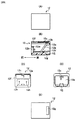
[図1]本発明に係るシャッター付き光コネクタにおけるプラグ1の平面図(A)、正面図(B)、左右側面図(C)、(D)である。
[図2]図1(A)中のB−B線に沿ったプラグ1の縦断面図(A)、横断面図(B)、図1(A)中のA−A線に沿った断面図(C)、シャッター1eの斜視図(D)である。
[図3]本発明に係るシャッター付き光コネクタ3におけるレセプタクル2の平面図(A)、正面図(B)、左側面図(C)、右側面図(D)である。
[図4]上記の図3(A)におけるB−B線に沿った断面図である。
[図5]本発明に係るシャッター付き光コネクタ3の使用状態である、接続作用を順次に示す説明図(A)、(B)、(C)である。
[図6]本発明の第2実施例に係るシャッター付き光コネクタにおけるプラグ9の、一部を断面にして示す平面図(A)、同正面図(B)、側面図(C)である。
[図7]本発明の第3実施例に係るシャッター付き光コネクタ13におけるプラグ11の、平面図(A)、正面図(B)、右側面図(C)、底面図(D)である。
[図8]本発明の第3実施例に係るシャッター付き光コネクタ13におけるレセプタクル12の、平面図(A)、縦断面図(B)、左側面図(C)、右側面図(D)、底面図(E)である。
[図9]本発明の第3実施例に係るシャッター付き光コネクタ13における、接続の様子を第1段階から第3段階に分けて示す、プラグ11の説明図(A)、と、縦断面図(B)である。FIG. 1 is a plan view (A), a front view (B), left and right side views (C) and (D) of a plug 1 in an optical connector with a shutter according to the present invention.
[FIG. 2] A longitudinal sectional view (A), a transverse sectional view (B), and a sectional view taken along line AA in FIG. 1 (A) of the plug 1 along the line BB in FIG. 1 (A). FIG. 2C is a perspective view of the
FIG. 3 is a plan view (A), a front view (B), a left side view (C), and a right side view (D) of the
[FIG. 4] A sectional view taken along line BB in FIG.
[FIG. 5] It is explanatory drawing (A), (B), (C) which shows the connection effect | action in order which is the use condition of the optical connector 3 with a shutter which concerns on this invention.
[FIG. 6] A plan view (A), a front view (B), and a side view (C) showing a part of the
FIG. 7 is a plan view (A), a front view (B), a right side view (C), and a bottom view (D) of a
[FIG. 8] A plan view (A), a longitudinal sectional view (B), a left side view (C), a right side view (D) of the
[FIG. 9] An explanatory view (A) of the
本発明の実施の形態として、コネクタ用プラグとコネクタ用レセプタクルとから成るシャッター付き光コネクタにおいて、互いに嵌合させることでシャッターが開口されるものと、更に、シャッターが容易に開けられないようにしたものを説明する。 As an embodiment of the present invention, in an optical connector with a shutter composed of a connector plug and a connector receptacle, the shutter is opened by being fitted to each other, and the shutter is not easily opened. Explain things.
第1実施例に係るシャッター付き光コネクタ3におけるプラグ1は、図1に示すように、合成樹脂製の、プラグハウジング1aと、固定ハウジング1bと、スライドハウジング1cと、及び、合成樹脂製のシャッター1eとから概略構成されている。 As shown in FIG. 1, the plug 1 in the optical connector 3 with a shutter according to the first embodiment is made of a synthetic resin, such as a
前記プラグハウジング1aには、図2に示すように、光ケーブル7を保持する固定ハウジング1bが嵌装されている。図2(A)、(C)に示すように、このプラグハウジング1aの内部空間部に、固定ハウジング1bの中央部における内部壁面から突出された円柱状のバネガイド1fが、略水平に片持支持されている。そこに、スプリング4が嵌装されている。 As shown in FIG. 2, a
前記スプリング4は、前記スライドハウジング1cの後壁面に一端側が当接して、それを前方向に押し出すように付勢する弾性部材である。 The
更に、図2(B)に示すように、前記バネガイド1fの先端部から前方向にファイバー損傷防止棒1gが突設されている。この先端部は、前記シャッター1eの位置から若干手前の位置にして、設けられている。 Further, as shown in FIG. 2 (B), a fiber
これにより、非接続時において、スライドハウジング1cが後方に押し込まれても、シャッター1eが前記ファイバー損傷防止棒1gの先端部に衝突することで、当該スライドハウジング1cが後方に後退しないようにされる。 Thereby, even when the
前記スライドハウジング1cは、図1乃至図2に示すように、その前面側に上下方向において、上に開口しているシャッター用空間部1hが設けられており、そこに、図2(D)に示すシャッター1eが遊嵌状態で収納される。 As shown in FIGS. 1 and 2, the
そして、前記シャッター1eが上方に抜け出さないように押さえる作用をするのが、図2(C)、(D)に示すように、押さえバネ5である。この実施例では、シャッター1eの上側中央部の切欠き部に押さえバネ5の一端を係止させている。 Then, as shown in FIGS. 2 (C) and 2 (D), the
前記シャッター1eは、後述のレセプタクル2の一部(退避手段)によって上方に押し上げられて、ファイバー6及びファイバー損傷防止棒1gの接続方向に沿った移動を許容する、開放状態になる。よって、このシャッター1eは、退避手段により、接続の邪魔にならないように光軸上から退避されれば良いので、上方に持ち上げられるほか、斜め上方もしくは下方に移動される構造でも良い。 The
前記シャッター用空間部1hにおいて、図1(C)及び図2(A)、(B)に示すように、前後方向に貫通させたファイバー用貫通孔1jが左右側に2カ所離間させて設けられている。この貫通孔1jに、レセプタクル2との接続状態において、光ケーブルのファイバー6が挿通されるものである。 In the
そして、このスライドハウジング1cの前端部には、レセプタクル2側のシャッターを開閉作用させる、テーパ部が形成されている。即ち、図1乃至図2に示すように、前記スライドハウジング1cの左右端部から前方に向けて壁面が延設され、そこに前方に行くに従って下に傾斜するテーパ部1m、1nが設けられている。なお、図1(C)に示すように、当該前端部の強度維持のために前記壁面をL字型に形成してある。そして、図1(A)に示すように、ある幅aを持たせて離間させてある。 A tapered portion is formed at the front end of the
このプラグハウジング1に、光ケーブル7を取り付ける。当該光ケーブル7のファイバー6は、その先端を前記貫通孔1jの入り口近傍に配設しておく。 An
次に、前記プラグ1に嵌合して接続されるレセプタクル2について説明する。
このレセプタクル2は、図3乃至図4に示すように、合成樹脂製で、一側面が開口されている箱体であり、その内部は前記プラグ1を受け入れるために大部分が空間部である。Next, the
As shown in FIGS. 3 to 4, the
図4(A)に示すように、上部の天井には、二つの四角形状の貫通孔が設けられ、そのうち、一つはシャッター収納部形成用の孔2aであり、他は、固定ハウジング1bの爪1p(図2(A)参照)と係合する係止孔2bである。 As shown in FIG. 4 (A), the upper ceiling is provided with two rectangular through holes, one of which is a
前記レセプタクル2の内部空間部2cには、図3(D)及び図4に示すように、その中央部に後方に行くほど上に傾斜する、退避手段としてのテーパ部2dが、設けられている。該テーパ部2dの左右方向の幅は、図1(A)にて示した前記スライドハウジング1cの幅a内に当該テーパ部2dが入り込むので、この幅aより若干狭い幅に設定される。 As shown in FIGS. 3D and 4, the
前記孔2aの位置の下側で、前記テーパ部2dの後部に、シャッター用収納部2eが図4に示すように形成されている。この収納部2eは、上部に開口された凹部であり、左右側壁部にはスリットが設けられている。図3に示すシャッター1eは、部品共通化のために図2(d)に示したシャッター1eと同じにされている。 A
このシャッター1eの耳部1rが、図3(C)、(D)に示すように、前記スリットから収納部2eの外に突出する。接続時に、前記テーパ部1m、1nに当該耳部1rが当接してその傾斜面に沿って移動することで、このシャッター1eを上下移動させるためである。 As shown in FIGS. 3C and 3D, the
また、前記シャッター1eが収納部2eから抜け出さないように、押さえ用のバネ2fが設けられている。 Further, a
更に、前記収納部2eを形成する前方壁面の下部に、前後方向において当該レセプタクル2の後壁面にまで貫通するファイバー6用の貫通孔2gが2個と、ファイバー損傷防止棒1g挿通用の貫通孔2hが1個設けられている。 Further, at the lower part of the front wall surface forming the
よって、前記シャッター1eが収納部2eに収納されていることで、前記貫通孔2hが閉ざされ、これが上方に持ち上げられることで貫通孔2hが開けられて、ファイバー損傷防止棒1gを前後方向に挿通させることが可能となる。 Therefore, when the
前記収納部2eのシャッター1eを持ち上げるのは、該収納部2eからスリットを介して内部空間部2cに突出している耳部1rに、前記プラグ1の前端部におけるテーパ部1m、1nが当接し、その進入によりなされるものである。 The
このようにして、プラグ1とレセプタクル2とが形成されシャッター付き光コネクタ3が構成される。そして、その接続・嵌合の様子を図5に沿って説明する。 In this way, the plug 1 and the
図5(A)に示すように、レセプタクル2の前方側の開口部に向かって、プラグ1のスライドハウジング1cを前にして差し込む。 As shown in FIG. 5A, the plug 1 is inserted with the
前記スライドハウジング1cがレセプタクル2の内部空間部2cに入り込み、そのテーパ部1m、1nが収納部2eのシャッター1eにおける耳部1rに当接する。また、ほぼ同時に、前記スライドハウジング1cにおけるシャッター用空間部1hのシャッター1eの下端部に、レセプタクル2側のテーパ部2dの下部が当接する。 The
図5(B)に示すように、前記プラグ1が、レセプタクル2に向けて更に挿入されると、前記耳部1rがテーパ部1m、1nによって上に押し上げられ、収納部2eのシャッター1eが、バネ2fの付勢力に抗して上に移動される。 As shown in FIG. 5B, when the plug 1 is further inserted toward the
また、ほぼ同時に、スライドハウジング1c側の前記シャッター1eも、前記テーパ部2dによってその下端部が押さえバネ5の付勢力に抗して押し上げられて、接続方向に直交する方向(上方向)に退避される。 At the same time, the lower end of the
この状態で、前記スライドハウジング1cにおけるシャッター用収納空間部1hを形成する前壁面と、前記レセプタクル2の収納部2eを形成する後壁面とが当接する。この状態まで、スプリング4の付勢力により、前記スライドハウジング1cが、プラグハウジング1aに対して後退することなく、挿入抵抗に抗して前進することができる。 In this state, the front wall surface that forms the
この後、図5(C)に示すように、プラグハウジング1aを更に押し込むことで、前記スプリング4が縮み、その付勢力に抗してプラグハウジング1aと固定ハウジング1bとが前進する。 Thereafter, as shown in FIG. 5C, when the
すると、前記収納部2eと収納空間部1hとにおける両シャッター1eが上方に移動しているので、バネガイド1fから突出しているファイバー損傷防止棒1gが、前記両シャッター1eに邪魔されることなく前進することができる。そして、当該ファイバー損傷防止棒1gは、貫通孔2hに挿通される。 Then, since both
また、2本のファイバー6(図2(B)参照)も、同様に、貫通孔1j(図2(B)参照)から貫通孔2g(図3(C)、(D)参照)へと挿通される。そして、このファイバー6がレセプタクル2側のファイバーと若干の当接力を有して当接し、光信号が伝達されるものである。 Similarly, the two fibers 6 (see FIG. 2B) are also inserted from the through
この接続状態を維持すべく、固定ハウジング1bの爪1pが、レセプタクル2の係止孔2bに係止される。接続解除の際には、この固定ハウジング1bのボタン1sを下方向に押すことで、前記爪1pの係止作用を解除させればよい。 In order to maintain this connected state, the claw 1 p of the fixed
このシャッター付き光コネクタ3においては、前記プラグ1とレセプタクル2との接続・解除の挿抜作用により両シャッター1eが開閉されるので、防塵効果があるばかりでなく、幼児などがファイバー6の端面を直接覗いて光信号により目に損傷を受けるおそれが無くなり、該ファイバー6も容易に露出されて折れ曲げられ損傷を受けるということがなくなり、確実に保護されるものである。 In this optical connector 3 with a shutter, both the
第2実施例に係るシャッター付き光コネクタは、図6に示すように、プラグにおけるファイバー6にフェルール8が設けられ、それにより、前記第1実施例のファイバー損傷防止棒1gが省略されている実施例である。 In the optical connector with a shutter according to the second embodiment, as shown in FIG. 6, the
このプラグ9は、光ケーブル7を装着する際に、ファイバー6にフェルール8を固定し、これにより、シャッター1eと当接させることで、スライドハウジング1cの後退を防止している。プラグ9の他の部分は、前記プラグ1と同じ構成であり、レセプタクル2との接続作用も前記第1実施例と同じであるので、省略する。 When the
本発明に係る第3実施例のシャッター付きコネクタ10は、図7に示すように、プラグ11において、スライドハウジング11a、特に前面壁11bがシャッターを兼用する。 In the
前記スライドハウジング11aが、例えば、幼児等の悪戯で後方向に押されても後退移動しないようにされ、レセプタクルとの接合時には、一旦、接続方向と直交する方向(上方向)に移動してから退避可能となるようにしたものである。 For example, the
また、図9に示すように、レセプタクル12において、防塵用のシャッター12aと前記プラグハウジング11cを上方に移動させるテーパ部12jを設けたものである。 Further, as shown in FIG. 9, the
前記プラグ11について詳述すると、図7に示すように、プラグハウジング11cの側壁には、スライドハウジング11aのスライドをガイドする、略逆L字型のガイド溝11dが設けられている。 The
一方、前記スライドハウジング11aの側壁には、前記ガイド溝11dに嵌合する、平板状の係合突起11eが設けられている。図7(B)に示す状態の時には、ガイド溝11dを形成する一部の弾性片11fの凹部11gにより、前記係合突起11eがロックされた状態となる。 On the other hand, on the side wall of the
前記スライドハウジング11aの前面壁11bには、ファイバー6用の貫通孔11hが設けられており、図7に示す状態ではファイバー6をカバーしている。このスライドハウジング11aが上に移動して更に後方に退避させた際に、ファイバー6と上下方向の高さ位置が合って、該ファイバー6がこの貫通孔11hから突出するようになる。このスライドハウジング11aの全体がシャッターの代わりとなる。 A through hole 11h for the fiber 6 is provided in the
符号11jは、光ケーブル7をロックする固定ハウジングを示している。この下面に、接続を維持する爪11kと、解除用のボタン11mが設けられている。
次に、前記レセプタクル12は、図8(B)、(D)に示すように、内部空間の開口部を全面的に閉蓋するシャッター12aが、上部で回転軸12bに回動自在に支持され、バネ12cで常に閉蓋する方向に付勢されて、設けられている。図示するように、シャッター12aの下部が突起12dに当接して、後方に斜めに傾斜されて設けられている。 Next, in the
また、前記突起12dの前面側で略中央部には、退避手段として、後方に行くほど上に傾斜するテーパ部12jが形成されている。これは、前記スライドハウジング11aを上に押し上げるためのものである。 Further, a tapered
このシャッター12aの上部には、前記スライドハウジング11aの光軸上への復帰手段として、軸部から略直交方向に展開させた係止突起12eが形成されており、プラグ11をレセプタクル12から脱着させた際に、当該スライドハウジング11aを下に押し下げる作用をする。 On the upper part of the
また、レセプタクル本体12fの下面には、図8(E)に示すように、係止孔12gが設けられ、プラグ11の爪11kが接続時に係止する。 Further, as shown in FIG. 8E, a
更に、図8(C)に示すように、レセプタクル本体12fの後壁面に、ファイバー6を挿通させる貫通孔12hが設けられている。 Further, as shown in FIG. 8C, a through
このようなプラグ11とレセプタクル12とによるシャッター付き光コネクタ13の接続と脱着との様子は、図9(A)、(B)に示すように3段階で行われる。即ち、同図(B)に示すように、第1段階では、レセプタクル12の前面の開口部にプラグ11のスライドハウジング11aが挿入されると、スライドハウジング11aの先端部でシャッター12aをバネ12cの付勢力に抗して後方に押し上げる。 The connection and removal of the
それとほぼ同時に、テーパ部12jにスライドハウジング11aの下部中央に形成されているテーパ部11rが当接する。これにより、スライドハウジング11aが前方に移動すると、前記テーパ部12jの傾斜面に沿って上に移動することになる。 At substantially the same time, the tapered
更に、第2段階で、プラグ11を前方に押し込むと、スライドハウジング11aが前進し、シャッター12aを上に回転させて完全に押し開けた状態になり、スライドハウジング11aも前記テーパ部12jによって上に移動する。 Further, when the
すると、スライドハウジング11aの貫通孔11hがフェルール11sの高さと一致するようになる。また、フェルール11sが前進できるようにスライドハウジング11aの前壁面の切欠部11u(図8(C)、(E)参照)が前方に位置する。こうして、フェルール11sの接続方向(前後方向)に沿った移動が許容された状態となる。 Then, the through hole 11h of the
更に、図9(A)の第2段階に示すように、係合突起11eが、ガイド溝11dの上位置にある前後方向の溝の位置に、その高さが合わせられて、前後方向の移動が可能になる。 Further, as shown in the second stage of FIG. 9A, the height of the engaging
次に、第3段階として、プラグ11のスライドハウジング11aの前壁面11bがレセプタクル12の後壁面12mに当接すると、該スライドハウジング11aの移動が停止して、プラグハウジング11c及び固定ハウジング11jが更に前進する。係合突起11eがガイド溝11dに沿って相対的に後方に移動する。 Next, as a third stage, when the
すると、フェルール11sが貫通孔12hに挿通し、スライドハウジング11aの前壁面11bから突出する。 Then, the
また、固定ハウジング11jの爪11kが、係止孔12gに係止し、プラグ11とレセプタクル12との接続状態が維持される。 Further, the
前記突出したフェルール11sが、若干押し戻されたスプリング11tによる付勢力で当接し、レセプタクル12側のフェルール(図示せず)と接続されて光信号の伝達がなされる。 The protruding
上記接続状態を解除するには、前記固定ハウジング11jのボタン11mを押すことで、前記爪11kの係止を解除させる。すると、プラグハウジング11c及び固定ハウジング11jが後方に移動させられる。前記フェルール11sが、突出状態からスライドハウジング11aの前壁面11bの内側に後退する。 In order to release the connection state, the locking of the
更に、後方に引き抜くと、スライドハウジング11aが、復帰手段である係止突起12eに当接して、テーパ部12jに沿って下方斜めに移動させられる。 When the
プラグ11を引き抜くに従って、シャッター12aがバネ12cの付勢力により下方に展開し、プラグ11が完全にレセプタクル12から抜去されると、シャッター12aの下部が、突起12dに当接して、奥行き側に傾斜した状態で閉蓋される。 As the
また、スライドハウジング11aが前方に移動して下に移動するので、凹部11gによりロックされて接続方向(前後方向)の移動が阻止されるようになる。また、フェルール11sも保護されるようになる。勿論、防塵効果も作用する。 Further, since the
他の実施例として、上記各実施例における爪1p、11kと係止孔2b、12gとの係止関係において、当該爪の深さを浅く加減することで、ある範囲での引抜力には抵抗するが、ある引抜力以上の力では抜けるようにして、係止作用が解除されるようにすることが、コネクタの破壊を防止する上で好ましいものである。 As another embodiment, in the locking relationship between the
以上のように、本発明に係るシャッター付き光コネクタは、光通信ケーブルの接続部に使用するものとして有用であり、特に、コネクタ用プラグとコネクタ用レセプタクルとの取り扱いにおいて高い安全性及び防塵性を有するので、会社間若しくは会社内におけるLANの構築や、一般家庭にまで光ケーブルを引き込むFTTH(Fiber To The Home)の構築などへの使用に適している。 As described above, the optical connector with a shutter according to the present invention is useful as a connection part of an optical communication cable, and particularly has high safety and dustproofness in the handling of a connector plug and a connector receptacle. Therefore, it is suitable for use in construction of a LAN between companies or in a company, construction of FTTH (Fiber To The Home) for drawing an optical cable to a general home, and the like.
Claims (4)
前記プラグとレセプタクルとに、接続時にはファイバーの接続用端部が光軸に
沿って移動するのを許容し非接続時には前記ファイバーの接続用端部の移動を阻止するシャッターが各々に設けられ、
当該両シャッターは、接続時に接続相手側の退避手段によって光軸上から退避させられて、前記プラグにおけるファイバーの接続用端部が前記プラグ側のシャッターの内側から外側に突出することで、レセプタクル側のファイバーとの接続がなされること、
を特徴とするシャッター付き光コネクタ。In an optical connector comprising a connector plug and a connector receptacle to which the plug is inserted / fitted and connected,
When connecting to the plug and receptacle, the connecting end of the fiber is on the optical axis.
Each is provided with a shutter that allows movement along and prevents movement of the fiber connection end when disconnected .
The two shutters are retracted from the optical axis by the retracting means on the connection partner side when connected, and the connection end of the fiber in the plug protrudes from the inside of the shutter on the plug side to the receptacle side. The connection with the fiber of
Optical connector with shutter.
を特徴とする請求項1に記載のシャッター付き光コネクタ。A shutter is provided on the slide housing of the plug, and a fiber bar damage preventing rod is disposed inside the shutter to prevent the slide housing from being retracted from the optical axis so as not to damage the connecting end of the fiber. Being
The optical connector with a shutter according to claim 1.
前記プラグとレセプタクルとに、接続時にはファイバーの接続用端部が光軸に沿って移動するのを許容し非接続時には前記ファイバーの接続用端部の移動を阻止するシャッターが各々に設けられ、
前記プラグ側のシャッターは、接続時にレセプタクルに挿入・嵌合されて光軸上から退避されてファイバーの接続用端部が光軸に沿って接続のために移動するのを許容するとともに、非接続時にはレセプタクルからの抜去で光軸上に移動されて前記ファイバーの接続用端部が光軸に沿って接続のために移動するのを阻止するスライドハウジングがシャッターを兼用し、
前記レセプタクル側には、前記スライドハウジングを光軸上から退避させる退避手段と光軸上に復帰させる復帰手段とが設けられていること、
を特徴とするシャッター付き光コネクタ。In an optical connector comprising a connector plug and a connector receptacle to which the plug is inserted / fitted and connected,
Each of the plug and the receptacle is provided with a shutter that allows the connection end of the fiber to move along the optical axis when connected and prevents the movement of the connection end of the fiber when not connected .
The plug-side shutter is inserted and fitted into the receptacle at the time of connection and retracted from the optical axis to allow the fiber connection end to move for connection along the optical axis and to be disconnected. Sometimes the slide housing that is moved on the optical axis by removal from the receptacle and prevents the connecting end of the fiber from moving for connection along the optical axis also serves as a shutter,
On the receptacle side, a retracting means for retracting the slide housing from the optical axis and a return means for returning to the optical axis are provided,
Optical connector with shutter.
前記プラグとレセプタクルとに、接続時にはファイバーの接続用端部が光軸に沿って移動するのを許容し非接続時には前記ファイバーの接続用端部の移動を阻止するシャッターが各々に設けられ、
前記レセプタクル側のシャッターは、プラグの挿抜作用で開閉するように回動自在に軸支されるとともに、前記レセプタクルの後方側に傾斜して設けられていること、
を特徴とするシャッター付き光コネクタ。In an optical connector comprising a connector plug and a connector receptacle to which the plug is inserted / fitted and connected,
Each of the plug and the receptacle is provided with a shutter that allows the connection end of the fiber to move along the optical axis when connected and prevents the movement of the connection end of the fiber when not connected .
The receptacle-side shutter is pivotally supported so as to open and close by a plug insertion / extraction action, and is provided to be inclined to the rear side of the receptacle;
Optical connector with shutter.
Applications Claiming Priority (1)
| Application Number | Priority Date | Filing Date | Title |
|---|---|---|---|
| PCT/JP2004/006448 WO2005111685A1 (en) | 2004-05-13 | 2004-05-13 | Optical connector with shutter |
Publications (2)
| Publication Number | Publication Date |
|---|---|
| JP4032073B2 true JP4032073B2 (en) | 2008-01-16 |
| JPWO2005111685A1 JPWO2005111685A1 (en) | 2008-03-27 |
Family
ID=35394294
Family Applications (1)
| Application Number | Title | Priority Date | Filing Date |
|---|---|---|---|
| JP2006518504A Expired - Fee Related JP4032073B2 (en) | 2004-05-13 | 2004-05-13 | Optical connector with shutter |
Country Status (2)
| Country | Link |
|---|---|
| JP (1) | JP4032073B2 (en) |
| WO (1) | WO2005111685A1 (en) |
Cited By (1)
| Publication number | Priority date | Publication date | Assignee | Title |
|---|---|---|---|---|
| US20210302663A1 (en) * | 2015-11-13 | 2021-09-30 | CommScope Connectivity Belgium BVBA | Fiber optic connection system |
Families Citing this family (2)
| Publication number | Priority date | Publication date | Assignee | Title |
|---|---|---|---|---|
| JP4881242B2 (en) * | 2007-07-09 | 2012-02-22 | 三菱電線工業株式会社 | Optical connector plug |
| WO2021163063A1 (en) * | 2020-02-11 | 2021-08-19 | Commscope Technologies Llc | Fiber optic connector with shutter |
Family Cites Families (4)
| Publication number | Priority date | Publication date | Assignee | Title |
|---|---|---|---|---|
| AU658999B2 (en) * | 1992-05-20 | 1995-05-04 | Diamond S.A. | Plug connector for optical fibers |
| JPH10300985A (en) * | 1997-04-23 | 1998-11-13 | Sumitomo Electric Ind Ltd | Multi-unit optical connector |
| US5883995A (en) * | 1997-05-20 | 1999-03-16 | Adc Telecommunications, Inc. | Fiber connector and adapter |
| JP3550368B2 (en) * | 2001-03-02 | 2004-08-04 | ヒロセ電機株式会社 | Optical connector |
-
2004
- 2004-05-13 JP JP2006518504A patent/JP4032073B2/en not_active Expired - Fee Related
- 2004-05-13 WO PCT/JP2004/006448 patent/WO2005111685A1/en active Application Filing
Cited By (1)
| Publication number | Priority date | Publication date | Assignee | Title |
|---|---|---|---|---|
| US20210302663A1 (en) * | 2015-11-13 | 2021-09-30 | CommScope Connectivity Belgium BVBA | Fiber optic connection system |
Also Published As
| Publication number | Publication date |
|---|---|
| WO2005111685A1 (en) | 2005-11-24 |
| JPWO2005111685A1 (en) | 2008-03-27 |
Similar Documents
| Publication | Publication Date | Title |
|---|---|---|
| JP4304213B2 (en) | Optical connector plug | |
| CN108508540B (en) | Optical fiber adapter | |
| JP4730092B2 (en) | Latch mechanism and electronic module with latch mechanism | |
| US8764313B2 (en) | Optical connector plug | |
| JP2006195227A (en) | Lock releasing mechanism of optical connector | |
| US20120093466A1 (en) | Optical connector plug having improved latching mechanism | |
| JP2018060040A (en) | Protection cap for optical connector plug | |
| JP4327063B2 (en) | Optical connector with shutter | |
| US6964526B2 (en) | Optical plug and optical connector provided with the optical plug | |
| JP6724094B2 (en) | Optical connector system and optical connector with shutter | |
| JP4032073B2 (en) | Optical connector with shutter | |
| US6481902B2 (en) | Light transmission device | |
| US10545295B1 (en) | Optical adapter with shutter | |
| JP2006126807A (en) | Optical outlet unit | |
| JP3147103U (en) | Optical connector socket | |
| JP2019184942A (en) | Mpo plug mini-adapter | |
| JP3946081B2 (en) | Optical connector socket | |
| JP2005092082A (en) | Optical fiber plug and optical fiber connector | |
| JP5006807B2 (en) | Optical connector plug | |
| JP4169207B2 (en) | Front cover of optical outlet unit | |
| JP4875599B2 (en) | Optical connector plug with shutter | |
| JP2574527B2 (en) | Optical connector | |
| JP3527886B2 (en) | Connector plug | |
| JP3573675B2 (en) | Optical connector socket | |
| JP5483580B2 (en) | Optical connector |
Legal Events
| Date | Code | Title | Description |
|---|---|---|---|
| TRDD | Decision of grant or rejection written | ||
| A01 | Written decision to grant a patent or to grant a registration (utility model) |
Free format text: JAPANESE INTERMEDIATE CODE: A01 Effective date: 20071003 |
|
| A61 | First payment of annual fees (during grant procedure) |
Free format text: JAPANESE INTERMEDIATE CODE: A61 Effective date: 20071022 |
|
| R150 | Certificate of patent or registration of utility model |
Free format text: JAPANESE INTERMEDIATE CODE: R150 |
|
| FPAY | Renewal fee payment (event date is renewal date of database) |
Free format text: PAYMENT UNTIL: 20101026 Year of fee payment: 3 |
|
| LAPS | Cancellation because of no payment of annual fees |