US8764313B2 - Optical connector plug - Google Patents
Optical connector plug Download PDFInfo
- Publication number
- US8764313B2 US8764313B2 US13/509,934 US201013509934A US8764313B2 US 8764313 B2 US8764313 B2 US 8764313B2 US 201013509934 A US201013509934 A US 201013509934A US 8764313 B2 US8764313 B2 US 8764313B2
- Authority
- US
- United States
- Prior art keywords
- optical connector
- plug
- adapter
- connector plug
- tapered portion
- Prior art date
- Legal status (The legal status is an assumption and is not a legal conclusion. Google has not performed a legal analysis and makes no representation as to the accuracy of the status listed.)
- Active, expires
Links
Images


Classifications
-
- G—PHYSICS
- G02—OPTICS
- G02B—OPTICAL ELEMENTS, SYSTEMS OR APPARATUS
- G02B6/00—Light guides; Structural details of arrangements comprising light guides and other optical elements, e.g. couplings
- G02B6/24—Coupling light guides
- G02B6/36—Mechanical coupling means
- G02B6/38—Mechanical coupling means having fibre to fibre mating means
- G02B6/3807—Dismountable connectors, i.e. comprising plugs
- G02B6/389—Dismountable connectors, i.e. comprising plugs characterised by the method of fastening connecting plugs and sockets, e.g. screw- or nut-lock, snap-in, bayonet type
- G02B6/3893—Push-pull type, e.g. snap-in, push-on
-
- G—PHYSICS
- G02—OPTICS
- G02B—OPTICAL ELEMENTS, SYSTEMS OR APPARATUS
- G02B6/00—Light guides; Structural details of arrangements comprising light guides and other optical elements, e.g. couplings
- G02B6/24—Coupling light guides
- G02B6/36—Mechanical coupling means
- G02B6/38—Mechanical coupling means having fibre to fibre mating means
- G02B6/3807—Dismountable connectors, i.e. comprising plugs
- G02B6/381—Dismountable connectors, i.e. comprising plugs of the ferrule type, e.g. fibre ends embedded in ferrules, connecting a pair of fibres
- G02B6/3825—Dismountable connectors, i.e. comprising plugs of the ferrule type, e.g. fibre ends embedded in ferrules, connecting a pair of fibres with an intermediate part, e.g. adapter, receptacle, linking two plugs
-
- G—PHYSICS
- G02—OPTICS
- G02B—OPTICAL ELEMENTS, SYSTEMS OR APPARATUS
- G02B6/00—Light guides; Structural details of arrangements comprising light guides and other optical elements, e.g. couplings
- G02B6/24—Coupling light guides
- G02B6/36—Mechanical coupling means
- G02B6/38—Mechanical coupling means having fibre to fibre mating means
- G02B6/3807—Dismountable connectors, i.e. comprising plugs
- G02B6/3833—Details of mounting fibres in ferrules; Assembly methods; Manufacture
- G02B6/3847—Details of mounting fibres in ferrules; Assembly methods; Manufacture with means preventing fibre end damage, e.g. recessed fibre surfaces
- G02B6/3849—Details of mounting fibres in ferrules; Assembly methods; Manufacture with means preventing fibre end damage, e.g. recessed fibre surfaces using mechanical protective elements, e.g. caps, hoods, sealing membranes
Definitions
- the present invention relates to an optical connector plug to be inserted into and extracted from a connector adapter, particularly relates to an optical connector plug which is easily inserted into and extracted from the connector adapter, and which is compatible with a SC type connector in the connector for optical fiber cord connection.
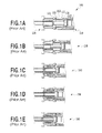
- FIG. 1A to FIG. 1E are diagrams showing a connecting mechanism 100 in the conventional SC type connector.
- FIG. 1A when a conventional SC type connector plug 110 is inserted into a connector adapter 120 , an adapter elastic locking piece 121 moves a flat part 112 at a tip part of a plug housing after moving along a slope 111 while being extended along the slope at the tip of the plug housing ( FIG. 1B ). Then, when the elastic locking piece 121 goes down along a slope 113 at a rear part of the plug housing, the tip of the elastic locking piece 121 falls in front of a suspending part 114 of a plug frame ( FIG. 1C ). If the plug 110 is furthermore pushed in, the plug 110 moves while the elastic locking piece 121 touches the suspending part 114 of the plug frame ( FIG. 1D ), and the elastic locking piece 121 is eventually fallen and locked by a step part 115 of the plug frame, and the engagement is attained ( FIG. 1E ).
- the adapter elastic locking piece 121 contacts a tip part of a plug housing, and by moving along the slope 111 , the elastic locking piece 121 is extended.
- the stress increases abruptly (symbol b).
- the elastic locking piece 121 moves along the flat part 112 of the plug housing, and the slope 113 , changes in stress are seen in FIG. 2 , and the stress becomes almost zero when the elastic locking piece 121 falls in front of the suspending part 114 of the plug frame (symbol c).
- the elastic locking piece 121 moves the suspending part 114 of the plug 110 on the other side (symbol d).
- the stress increases as a ferrule of the plug starts contacting a partner ferrule on the other side, and the stress becomes almost zero when the elastic locking piece 121 falls in the step part 115 of the plug, and is stopped, whereby the plug is in the completely connected state (symbol e).
- a repulsive force from the ferrule on the other side is added, and the stress increases again.
- the above measures may be effective. However, under bad installation conditions of the adapter 120 , it may be hard to hear the sound when connected, or the white line is hard to recognize if the connector housing cannot be seen directly. Therefore, in fact it is difficult to completely prevent the half-way insertion. Furthermore, as the FTTH becomes popular, the cases where unskilled workers or ordinary people deal with the optical connector are increasing, and the measure for preventing this state of half-way insertion is more necessitated.
- the present invention has been made in view of the above circumstances and provides an optical connector plug which can prevent an occurrence of such phenomena that a connecting stress is reduced to zero or lowered on the way in a process of inserting or extracting, or preventing an occurrence of a half-way insertion on the way of inserting or extracting process, when a general person other than a professional construction worker inserts or extracts the optical connector.
- the optical connector plug of the present invention is the optical connector plug to be inserted into an adapter, wherein a pair of engaging parts for expanding an elastic locking piece provided on a side of the adapter by a taper part and locking it with a step part is provided on a tip part of a plug frame which is a body of the plug; a locking releasing piece movable along an insertion-extraction direction is provided between the pair of engaging parts; a taper part for releasing a locking action of the elastic locking piece when extracting the plug is provided at a rear end of the locking releasing piece; and the taper part of the engaging parts has such a shape that the connecting stress is not lowered before being locked when inserting the plug.
- the optical connector plug includes a flat face between the taper part and the step part of the engaging part.
- the taper part of the engaging part has a multistage tapered shape.
- the optical connector housing is provided with a light-shielding member.
- both the frame front part and frame center part of the plug form slopes, more preferably form slopes with constant inclination, whereby the stress increases gradually until the adapter locking piece falls in the suspending part of the plug frame, and it is possible to hold a change amount in stress to the same as possible.
- the stress does not decrease in the middle when connecting the plug.
- the worker who connects the connector plug does not misunderstand that the plug is inserted in the suspending part and connected completely, thereby preventing the half-way insertion.
- conventional SC type connector has a slope angle of a front part of the plug frame of 25° to 35°.
- the smaller is this slope angle the smaller is the stress when connecting the plug frame to the adapter.
- the taper part for extraction at a rear part of the plug housing of the conventional SC type connector is not needed, there is an advantage that the slope angle can be made smaller.
- FIG. 1A is a drawing explaining a connecting mechanism of a SC type connector using conventional technology
- FIG. 1B is a drawing explaining the connecting mechanism of the SC type connector using conventional technology
- FIG. 1C is a drawing explaining the connecting mechanism of the SC type connector using conventional technology
- FIG. 1D is a drawing explaining the connecting mechanism of the SC type connector using conventional technology
- FIG. 1E is a drawing explaining the connecting mechanism of the SC type connector using conventional technology
- FIG. 2 is a drawing showing changes in stress when connecting the SC type connector using conventional technology
- FIG. 3A is a drawing explaining a connecting mechanism of an optical connector plug according to an embodiment in the examination process of the invention of the present invention
- FIG. 3B is a drawing explaining the connecting mechanism of the optical connector plug according to the embodiment in the examination process of the invention of the present invention.
- FIG. 3C is a drawing explaining the connecting mechanism of the optical connector plug according to the embodiment in the examination process of the invention of the present invention.
- FIG. 3D is a drawing explaining the connecting mechanism of the optical connector plug according to the embodiment in the examination process of the invention of the present invention.
- FIG. 4 is a drawing showing changes in stress when connecting the optical connector plug according to the embodiment in the examination process of the invention of the present invention this application;
- FIG. 5A is a drawing explaining a connecting mechanism of an optical connector plug according to a first embodiment of the present invention.
- FIG. 5B is a drawing explaining the connecting mechanism of the optical connector plug according to the first embodiment of the present invention.
- FIG. 5C is a drawing explaining the connecting mechanism of the optical connector plug according to the first embodiment of the present invention.
- FIG. 5D is a drawing explaining the connecting mechanism of the optical connector plug according to the first embodiment of the present invention.
- FIG. 5E is a drawing explaining the connecting mechanism of the optical connector plug according to the first embodiment of the present invention.
- FIG. 6 is a drawing showing changes in stress when connecting the optical connector plug according to the first embodiment of the present invention.
- FIG. 7A is a drawing showing a variation of a slope form of a plug frame of the optical connector plug according to the first embodiment of the present invention.
- FIG. 7B is a drawing showing a variation of a slope form of a plug frame of the optical connector plug according to the first embodiment of the present invention.
- FIG. 8 is a drawing showing an outline of the optical connector plug with a light-shielding member according to a second embodiment of the present invention.
- the patent literature 2 discloses a connector plug of SC type conformity.
- the adapter disclosed in the patent literature 2 is the same as that of the SC type connector adapter shown in FIG. 1A to FIG. 1E , and only the form of a connector plug differs.
- a configuration wherein a tip slope is added to the connector plug disclosed in the patent literature 2 is considered.
- FIG. 3A to FIG. 3D are drawings explaining a connecting mechanism 300 of a connector according to an embodiment in the examination process of the present invention.
- an elastic locking piece 321 of an adapter 320 is opened directly by a front part 311 of the plug frame ( FIG. 3B ), and after moving along a flat part 312 of the plug frame ( FIG. 3C ), the locking piece 321 falls in a step part 313 of the plug frame ( FIG. 3D ).
- the elastic locking piece 321 is opened by a pulling plate 314 located between a plug frame 310 and the elastic locking piece 321 , to come off from the step part 313 .
- FIG. 4 is a drawing showing changes in stress 400 when the connector plug 310 is inserted into the adapter 320 .
- the elastic locking piece 121 falls by the slope 113 at the rear part of the plug housing, which surrounds the plug frame 110 .
- the connector plug 310 shown in FIG. 3A through FIG. 3D since the elastic locking piece 321 does not fall on the way, it is not seen that the stress becomes zero. As a result, the state of the half-way insertion is less likely to occur as compared to the SC type connector of the conventional technology.
- FIG. 5A through 5E are drawings explaining a connecting mechanism 500 of the optical connector plug according to the first embodiment of the present invention.
- an optical connector plug 510 which has a locking releasing piece 514 in the position which adjoins a frame part extends a locking piece 521 of a connector adapter 520 by an approximately 10 tip taper part 511 as pushing in a plug ( FIG. 5B ).
- the locking piece 521 can extend gradually by an approximately 8° loose continuous central slope 512 , and a rear flat part is moved ( FIG. 5C ), finally it falls in a step part 513 , and the connector plug 510 and the connector adapter 520 connect in ( FIG. 5D ).
- the plug 510 When releasing the connected plug 510 from the adapter 520 , the plug 510 is retreated, while retreating the locking releasing piece 514 and releasing the locking piece 521 from the step part 513 ( FIG. 5E ).
- FIG. 6 is a drawing showing changes in stress 600 when connecting the optical connector plug according to the first embodiment of the present invention.
- the connector shown in FIG. 3A through FIG. 3D is extended along an approximately 33° slope at an internal tip of the plug frame.
- the optical connector plug 510 according to the first embodiment of the present invention is extended along the approximately 10° slope 512 .
- the stress when starting the connecting decreases from approximately 10 N to approximately 4 N.
- the connector shown in FIG. 3A through FIG. 3D moves on the flat frame on the way of insertion, and therefore, the stress drops down from the initial state of connecting although the stress does not become zero.
- the elastic locking piece 521 is only gradually extended as the plug 510 is inserted into the adapter 520 .
- the connecting stress hardly reduces from that in the initial state of connecting, but is increased again after the plug 510 contacts the ferrule on the other side, and the elastic locking piece 521 falls in the step part. Then, the stress decreases and connecting is completed.
- the optical connector plug according to the present invention has a smaller stress in early stages of insertion and the connecting stress in the middle of insertion hardly reduces but increases gradually compared with the stress of connector shown in FIG. 3A through FIG. 3D . As a result, the state of the half-way insertion is still less likely to occur.
- the width at a tip part of a taper part is almost equal to distances 705 , 715 of the two locking pieces, and as for the slope, it is desirable that the inclination be as small as possible, and as continuous as possible so that the abrupt change in connecting stress does not occur.
- the second embodiment is an embodiment provided with a light-shielding member disclosed in the patent literature 3.
- FIG. 8 is a drawing showing an outline of a connector 800 provided with a light-shielding member according to the second embodiment of the present invention.
- the light-shielding member is made up of a shutter housing 804 which surrounds an outside of a tubular plug frame 803 which stores therein and supports a ferrule 802 holding a tip part of an optical fiber 801 , so as to make a freely slidable contact with the tubular plug frame 803 , and which is inserted inside the opening part for connecting of a receptacle connector to be connected when connecting the optical connector; a shutter 805 , one end part of which is supported by the housing at a front part of the shutter housing 804 , the other end portion of which is energized by the elastic force from a spring 806 so as to shield the optical fiber 801 at the front portion of the ferrule 802 to be closed; and an elastic member (not shown), provided inside the shutter housing 804 , always energizing the shutter housing 804 forwards, which is provided in a spacing between the rear part of the plug frame 803 and the shutter housing 804 .
- the shutter housing 804 surrounds the outside of the tubular plug frame 803 which stores therein and supports the ferrule 802 holding the tip part of the optical fiber 801 , so as to make a freely slidable contact with the tubular plug frame 803 , and is inserted inside the opening part for connecting of the receptacle connector. Therefore, the guide nature when mounting can be exhibited, and even if the light-shielding member is added on the side of the plug, there is no need of improvement in particular on the receptacle connector side of the other side of connecting, and it can be connected in the same manner as the conventional manner.
- the light-shielding member is highly versatile. Furthermore, the light-shielding member does not go outside the outside dimension of the plug housing of an optical plug connector, and therefore does not become an obstacle in a high density assembly.
- the connecting mechanism of the optical connector plug described in the first embodiment of the present invention shown in FIG. 5A through 5E can be adopted also in the configuration provided with the light-shielding member shown in FIG. 8 , and changes in stress when connecting the optical connector plug as shown in FIG. 6 can be reproduced.
- both the frame front part and frame center part of the plug form slopes, more preferably form slopes with constant inclination, whereby the stress increases gradually until the adapter locking piece falls in the suspending part of the plug frame, and it is possible to suppress a decrease in stress to the minimum.
- the stress does not decrease in the middle when connecting the plug.
- the worker who connects the connector plug does not misunderstand that the plug is inserted in the suspending part, thereby preventing the half-way insertion.
- conventional SC connector has a slope angle of a front part of the plug frame of 25° to 35°.
- the taper part for extraction at a rear part of the plug housing of the conventional SC type connector is not needed, there is an advantage that the slope angle can be made smaller.
- the length of the flat part parallel to the movement direction of the plug between the slope part in the frame center portion and the step part of the frame rear portion is defined such that the extended locking piece can be surely mounted to the flat portion in the generally used SC type connector.
- the optical connector plug of the present invention the length can be shortened to the minimum.
- the slope angle can be made to a low angle, and changes in stress can be prevented from being generated.
Landscapes
- Physics & Mathematics (AREA)
- General Physics & Mathematics (AREA)
- Optics & Photonics (AREA)
- Mechanical Coupling Of Light Guides (AREA)
Abstract
Description
- PTL 1: Japanese Patent Laid-Open No. s62-78507 (1987)
- PTL 2: Japanese Patent Publication No. 4215577
- PTL 3: Japanese Patent Laid-Open No. 2008-176297
-
- 110 SC type connector plug by conventional technology
- 111 slope at tip of plug housing
- 112 flat part at tip part of plug housing
- 113 slope at rear part of plug housing
- 114 suspending part of plug frame
- 115, 313, 513 step part
- 120, 320, 520 adapter
- 121, 321, 521 elastic locking piece
- 310 connector plug of
patent literature 1 - 311 front part of plug frame
- 312 flat part of plug frame
- 314, 514 pulling plate
- 510 connector plug of the present invention
- 511 tip taper part
- 512 central slope
- 515 rear flat part
- 705 elastic locking piece interval
- 801 optical fiber
- 802 ferrule
- 803 plug frame
- 804 shutter housing
- 805 shutter
- 806 spring
Claims (17)
Applications Claiming Priority (3)
| Application Number | Priority Date | Filing Date | Title |
|---|---|---|---|
| JP2009-261822 | 2009-11-17 | ||
| JP2009261822A JP5182893B2 (en) | 2009-11-17 | 2009-11-17 | Optical connector plug |
| PCT/JP2010/006727 WO2011061926A1 (en) | 2009-11-17 | 2010-11-17 | Optical connector plug |
Publications (2)
| Publication Number | Publication Date |
|---|---|
| US20120219253A1 US20120219253A1 (en) | 2012-08-30 |
| US8764313B2 true US8764313B2 (en) | 2014-07-01 |
Family
ID=44059413
Family Applications (1)
| Application Number | Title | Priority Date | Filing Date |
|---|---|---|---|
| US13/509,934 Active 2031-05-27 US8764313B2 (en) | 2009-11-17 | 2010-11-17 | Optical connector plug |
Country Status (4)
| Country | Link |
|---|---|
| US (1) | US8764313B2 (en) |
| JP (1) | JP5182893B2 (en) |
| CN (1) | CN102667562B (en) |
| WO (1) | WO2011061926A1 (en) |
Cited By (3)
| Publication number | Priority date | Publication date | Assignee | Title |
|---|---|---|---|---|
| US20140219624A1 (en) * | 2013-02-06 | 2014-08-07 | Xyratex Technology Limited | Optical connector |
| US10830964B2 (en) * | 2018-06-05 | 2020-11-10 | Rosenberger(Shanghai)Technology Co., Ltd. | Optical fiber connector |
| US20230324632A1 (en) * | 2020-09-25 | 2023-10-12 | Sumitomo Electric Industries, Ltd. | Ferrule, optical connector, and optical connection structure |
Families Citing this family (8)
| Publication number | Priority date | Publication date | Assignee | Title |
|---|---|---|---|---|
| JP5182893B2 (en) * | 2009-11-17 | 2013-04-17 | Nttエレクトロニクス株式会社 | Optical connector plug |
| CN102707391B (en) * | 2011-10-21 | 2015-03-11 | 徐秋霜 | Method and device for field assembly of monitorable optical fiber movable connector |
| CN103217747B (en) * | 2013-03-04 | 2015-04-29 | 中航光电科技股份有限公司 | Optical fiber connector branching device |
| US9946034B1 (en) * | 2017-03-29 | 2018-04-17 | Amazon Technologies, Inc. | Contamination prevention system for fiber optic cabling |
| CN207965228U (en) * | 2017-11-14 | 2018-10-12 | 烽火通信科技股份有限公司 | A kind of joint of connector, adapter and fast insert-pull |
| EP4105946B1 (en) * | 2017-11-15 | 2024-01-03 | Nippon Telegraph and Telephone Corporation | Elastic wiring and method for producing elastic wiring |
| WO2019231450A1 (en) * | 2018-05-31 | 2019-12-05 | Corning Optical Communications LLC | Fiber optic connector having a comrpessible body and complimentary receptacle along with methods of making |
| CN110989097A (en) * | 2019-12-19 | 2020-04-10 | 武汉邮埃服光电科技有限公司 | Optical fiber adapter connecting assembly |
Citations (37)
| Publication number | Priority date | Publication date | Assignee | Title |
|---|---|---|---|---|
| US3806225A (en) * | 1972-11-28 | 1974-04-23 | G Codrino | Terminal fastener for light-guide cables |
| JPS57161820A (en) | 1981-03-16 | 1982-10-05 | Amp Inc | Optical guidewave tube connector |
| JPS61196482A (en) | 1985-02-21 | 1986-08-30 | イング・チイ・オリベツチ・アンド・チイ・エス・ピー・ア | Device for recording/reading binary information on magnetic disks |
| JPS6278507A (en) | 1985-09-30 | 1987-04-10 | Nec Corp | Optical connector |
| US4726647A (en) * | 1985-03-19 | 1988-02-23 | Sumitomo Electric Industries, Ltd. | Optical connector |
| US4875754A (en) * | 1987-08-28 | 1989-10-24 | Minnesota Mining And Manufacturing Company | Optical fiber connector |
| US4998796A (en) * | 1990-02-27 | 1991-03-12 | At&T Bell Laboratories | Method of assembling multi-grooved silicon chip fiber optic terminations |
| US5136672A (en) * | 1990-06-21 | 1992-08-04 | Amp Incorporated | Fiber protector |
| US5465313A (en) * | 1994-06-29 | 1995-11-07 | Molex Incorporated | Optical fiber connector and method of fabricating same |
| US5542015A (en) * | 1993-04-08 | 1996-07-30 | The Whitaker Corporation | Optical fiber connector latching mechanism |
| US5993071A (en) * | 1996-09-30 | 1999-11-30 | The Whitaker Corporation | Apparatus for connecting optical fibre connectors |
| US6022151A (en) * | 1996-09-27 | 2000-02-08 | Siemens Aktiengesellschaft | Optical module |
| US20010019647A1 (en) * | 2000-02-28 | 2001-09-06 | Alps Electric Co. Ltd. | Optical fiber connector and optical communication module using the same |
| US6290527B1 (en) * | 1998-07-03 | 2001-09-18 | Nippon Telegraph And Telephone Corp. | Nippon telegraph and telephone corporation |
| US6435728B2 (en) * | 1999-10-29 | 2002-08-20 | The Furukawa Electric Co., Ltd. | Optical connector housing, optical connector using the optical connector housing, and connection structure between an optical connector using the same optical connector housing and an optical component |
| US20020122634A1 (en) * | 2001-03-02 | 2002-09-05 | Hirose Electric Co., Ltd. | Ferrule holding structure for optical connector component |
| US20020159717A1 (en) * | 2001-03-02 | 2002-10-31 | Hirose Electric Co., Ltd | One-piece construction of plug frame for optical connector component |
| US20020159716A1 (en) * | 2000-04-14 | 2002-10-31 | Yoshiaki Ohbayashi | Micro optical connector and portable electronic device with connection terminal into which plug of the optical connector is plugged |
| US20030049000A1 (en) * | 2001-09-07 | 2003-03-13 | Hung-Yi Wu | Transceiver module with an unlocking device |
| US6585423B1 (en) * | 1996-06-28 | 2003-07-01 | The Whitaker Corporation | Connector system having interlocking inner housing |
| US20040017982A1 (en) * | 2002-04-16 | 2004-01-29 | Masahiro Nakajima | Optical functioning component |
| US20040033028A1 (en) * | 2002-08-13 | 2004-02-19 | Cheng Yung Chang | Optical fiber converter |
| US6718091B2 (en) * | 1999-10-19 | 2004-04-06 | Sharp Kabushiki Kaisha | Optical cable for an optical transmission and reception system |
| US20040072454A1 (en) * | 2002-09-06 | 2004-04-15 | Masahiro Nakajima | Optical connector plug, optical connector adapter and optical connector |
| JP2005017602A (en) | 2003-06-25 | 2005-01-20 | Honda Tsushin Kogyo Co Ltd | Plug with extraction jig |
| WO2005020374A2 (en) | 2003-08-19 | 2005-03-03 | Spacelabs Medical, Inc. | Latching medical patient parameter safety connector and method |
| US6913394B2 (en) * | 1999-06-01 | 2005-07-05 | Nippon Telegraph And Telephone Corporation | Optical connector plug, manufacturing method thereof and assembling tool |
| CN1767270A (en) | 2004-10-29 | 2006-05-03 | 安普泰科电子有限公司 | Coupler for flat cable and electric connector assembly |
| JP2006147283A (en) | 2004-11-18 | 2006-06-08 | Sharp Corp | connector |
| US7093983B2 (en) * | 2003-12-05 | 2006-08-22 | Seikoh Giken Co., Ltd. | Optical connector plug and optical connector |
| US7287912B2 (en) * | 2004-12-28 | 2007-10-30 | Japan Aviation Electronics Industry, Limited | Optical connector improved in mountability without an increase in number of components |
| US20080095504A1 (en) * | 2006-08-07 | 2008-04-24 | Seikoh Giken Co., Ltd. | Optical Connector Component and Optical Connector Using the Same |
| JP2008176297A (en) | 2006-12-20 | 2008-07-31 | Honda Tsushin Kogyo Co Ltd | Optical connector plug with light shielding member |
| US20090310919A1 (en) * | 2008-06-12 | 2009-12-17 | Seikoh Giken Co., Ltd. | Optical connector stop ring, optical fiber cord with optical connector using the same and method for manufacturing optical fiber cord with optical connector |
| US7654849B2 (en) * | 2007-03-22 | 2010-02-02 | Edwards Lifesciences Corporation | Releasably locking auto-aligning fiber optic connector |
| US8224144B2 (en) * | 2008-10-31 | 2012-07-17 | Tyco Electronics Corporation | Fiber optic connector storage apparatus and methods for using the same |
| US20120219253A1 (en) * | 2009-11-17 | 2012-08-30 | Ntt Electronics Corporation | Optical connector plug |
Family Cites Families (1)
| Publication number | Priority date | Publication date | Assignee | Title |
|---|---|---|---|---|
| JPH0211743Y2 (en) * | 1985-05-30 | 1990-03-28 |
-
2009
- 2009-11-17 JP JP2009261822A patent/JP5182893B2/en not_active Expired - Fee Related
-
2010
- 2010-11-17 US US13/509,934 patent/US8764313B2/en active Active
- 2010-11-17 WO PCT/JP2010/006727 patent/WO2011061926A1/en not_active Ceased
- 2010-11-17 CN CN201080052244.4A patent/CN102667562B/en not_active Expired - Fee Related
Patent Citations (50)
| Publication number | Priority date | Publication date | Assignee | Title |
|---|---|---|---|---|
| US3806225A (en) * | 1972-11-28 | 1974-04-23 | G Codrino | Terminal fastener for light-guide cables |
| JPS57161820A (en) | 1981-03-16 | 1982-10-05 | Amp Inc | Optical guidewave tube connector |
| US4415232A (en) | 1981-03-16 | 1983-11-15 | Amp Incorporated | Optical waveguide splice |
| JPS61196482A (en) | 1985-02-21 | 1986-08-30 | イング・チイ・オリベツチ・アンド・チイ・エス・ピー・ア | Device for recording/reading binary information on magnetic disks |
| US4726647A (en) * | 1985-03-19 | 1988-02-23 | Sumitomo Electric Industries, Ltd. | Optical connector |
| JPS6278507A (en) | 1985-09-30 | 1987-04-10 | Nec Corp | Optical connector |
| US4875754A (en) * | 1987-08-28 | 1989-10-24 | Minnesota Mining And Manufacturing Company | Optical fiber connector |
| US4998796A (en) * | 1990-02-27 | 1991-03-12 | At&T Bell Laboratories | Method of assembling multi-grooved silicon chip fiber optic terminations |
| US5136672A (en) * | 1990-06-21 | 1992-08-04 | Amp Incorporated | Fiber protector |
| US5542015A (en) * | 1993-04-08 | 1996-07-30 | The Whitaker Corporation | Optical fiber connector latching mechanism |
| US5764834A (en) * | 1993-04-08 | 1998-06-09 | The Whitaker Corporation | Optical fibre connector latching mechanism |
| US5465313A (en) * | 1994-06-29 | 1995-11-07 | Molex Incorporated | Optical fiber connector and method of fabricating same |
| US6585423B1 (en) * | 1996-06-28 | 2003-07-01 | The Whitaker Corporation | Connector system having interlocking inner housing |
| US6022151A (en) * | 1996-09-27 | 2000-02-08 | Siemens Aktiengesellschaft | Optical module |
| US5993071A (en) * | 1996-09-30 | 1999-11-30 | The Whitaker Corporation | Apparatus for connecting optical fibre connectors |
| US6290527B1 (en) * | 1998-07-03 | 2001-09-18 | Nippon Telegraph And Telephone Corp. | Nippon telegraph and telephone corporation |
| US6913394B2 (en) * | 1999-06-01 | 2005-07-05 | Nippon Telegraph And Telephone Corporation | Optical connector plug, manufacturing method thereof and assembling tool |
| US6718091B2 (en) * | 1999-10-19 | 2004-04-06 | Sharp Kabushiki Kaisha | Optical cable for an optical transmission and reception system |
| US6435728B2 (en) * | 1999-10-29 | 2002-08-20 | The Furukawa Electric Co., Ltd. | Optical connector housing, optical connector using the optical connector housing, and connection structure between an optical connector using the same optical connector housing and an optical component |
| US20010019647A1 (en) * | 2000-02-28 | 2001-09-06 | Alps Electric Co. Ltd. | Optical fiber connector and optical communication module using the same |
| US20020159716A1 (en) * | 2000-04-14 | 2002-10-31 | Yoshiaki Ohbayashi | Micro optical connector and portable electronic device with connection terminal into which plug of the optical connector is plugged |
| US20020122634A1 (en) * | 2001-03-02 | 2002-09-05 | Hirose Electric Co., Ltd. | Ferrule holding structure for optical connector component |
| US20020159717A1 (en) * | 2001-03-02 | 2002-10-31 | Hirose Electric Co., Ltd | One-piece construction of plug frame for optical connector component |
| US6599027B2 (en) * | 2001-03-02 | 2003-07-29 | Hirose Electric Co., Ltd. | Ferrule holding structure for optical connector component |
| US6776535B2 (en) * | 2001-03-02 | 2004-08-17 | Hirose Electric Co., Ltd. | One-piece construction of plug frame for optical connector component |
| US20030049000A1 (en) * | 2001-09-07 | 2003-03-13 | Hung-Yi Wu | Transceiver module with an unlocking device |
| US20040017982A1 (en) * | 2002-04-16 | 2004-01-29 | Masahiro Nakajima | Optical functioning component |
| US7090409B2 (en) * | 2002-04-16 | 2006-08-15 | Nippon Telegraph And Telephone Corporation And Seikoh Giken Co., Ltd. | Optical functioning component and optical connector having optical functioning component |
| US6783281B2 (en) * | 2002-08-13 | 2004-08-31 | Hon Hai Precision Ind. Co., Ltd. | Optical fiber converter retaining different sized ferrules |
| US20040033028A1 (en) * | 2002-08-13 | 2004-02-19 | Cheng Yung Chang | Optical fiber converter |
| US20040072454A1 (en) * | 2002-09-06 | 2004-04-15 | Masahiro Nakajima | Optical connector plug, optical connector adapter and optical connector |
| US20050226568A1 (en) * | 2002-09-06 | 2005-10-13 | Masahiro Nakajima | Optical connector plug, optical connector adapter and optical connector |
| US20050232550A1 (en) * | 2002-09-06 | 2005-10-20 | Masahiro Nakajima | Optical connector plug, optical connector adapter and optical connector |
| JP2005017602A (en) | 2003-06-25 | 2005-01-20 | Honda Tsushin Kogyo Co Ltd | Plug with extraction jig |
| WO2005020374A2 (en) | 2003-08-19 | 2005-03-03 | Spacelabs Medical, Inc. | Latching medical patient parameter safety connector and method |
| JP2007503095A (en) | 2003-08-19 | 2007-02-15 | スペースラブズ メディカル, インコーポレイテッド | Medical patient parameter safety latch connector and method |
| US7093983B2 (en) * | 2003-12-05 | 2006-08-22 | Seikoh Giken Co., Ltd. | Optical connector plug and optical connector |
| US20060094284A1 (en) | 2004-10-29 | 2006-05-04 | Masayuki Aizawa | Coupler for flat cables and electrical connector assembly |
| JP2006127943A (en) | 2004-10-29 | 2006-05-18 | Tyco Electronics Amp Kk | Coupler for flat cable and electric connector assembly |
| CN1767270A (en) | 2004-10-29 | 2006-05-03 | 安普泰科电子有限公司 | Coupler for flat cable and electric connector assembly |
| JP2006147283A (en) | 2004-11-18 | 2006-06-08 | Sharp Corp | connector |
| US7287912B2 (en) * | 2004-12-28 | 2007-10-30 | Japan Aviation Electronics Industry, Limited | Optical connector improved in mountability without an increase in number of components |
| US20080095504A1 (en) * | 2006-08-07 | 2008-04-24 | Seikoh Giken Co., Ltd. | Optical Connector Component and Optical Connector Using the Same |
| JP2008176297A (en) | 2006-12-20 | 2008-07-31 | Honda Tsushin Kogyo Co Ltd | Optical connector plug with light shielding member |
| US20080247709A1 (en) | 2006-12-20 | 2008-10-09 | Toshiaki Eguchi | Shading member-equipped optical connector plug |
| US7559700B2 (en) * | 2006-12-20 | 2009-07-14 | Honda Tsushin Kogyo Co., Ltd. | Shading member-equipped optical connector plug |
| US7654849B2 (en) * | 2007-03-22 | 2010-02-02 | Edwards Lifesciences Corporation | Releasably locking auto-aligning fiber optic connector |
| US20090310919A1 (en) * | 2008-06-12 | 2009-12-17 | Seikoh Giken Co., Ltd. | Optical connector stop ring, optical fiber cord with optical connector using the same and method for manufacturing optical fiber cord with optical connector |
| US8224144B2 (en) * | 2008-10-31 | 2012-07-17 | Tyco Electronics Corporation | Fiber optic connector storage apparatus and methods for using the same |
| US20120219253A1 (en) * | 2009-11-17 | 2012-08-30 | Ntt Electronics Corporation | Optical connector plug |
Non-Patent Citations (2)
| Title |
|---|
| International Search Report issued Jan. 11, 2011 for PCT/JP2010/006727, filed Nov. 17, 2010. |
| Office Action dated Dec. 4, 2013 in corresponding Chinese Patent Application No. 201080052244.4. |
Cited By (6)
| Publication number | Priority date | Publication date | Assignee | Title |
|---|---|---|---|---|
| US20140219624A1 (en) * | 2013-02-06 | 2014-08-07 | Xyratex Technology Limited | Optical connector |
| US9128256B2 (en) * | 2013-02-06 | 2015-09-08 | Xyratex Technology Limited | Optical connector |
| US9523822B2 (en) | 2013-02-06 | 2016-12-20 | Xyratex Technology Limited | Optical connector |
| US10107970B2 (en) | 2013-02-06 | 2018-10-23 | Xyratex Technology Limited | Optical connector |
| US10830964B2 (en) * | 2018-06-05 | 2020-11-10 | Rosenberger(Shanghai)Technology Co., Ltd. | Optical fiber connector |
| US20230324632A1 (en) * | 2020-09-25 | 2023-10-12 | Sumitomo Electric Industries, Ltd. | Ferrule, optical connector, and optical connection structure |
Also Published As
| Publication number | Publication date |
|---|---|
| JP5182893B2 (en) | 2013-04-17 |
| CN102667562B (en) | 2015-11-25 |
| CN102667562A (en) | 2012-09-12 |
| US20120219253A1 (en) | 2012-08-30 |
| JP2011107381A (en) | 2011-06-02 |
| WO2011061926A1 (en) | 2011-05-26 |
Similar Documents
| Publication | Publication Date | Title |
|---|---|---|
| US8764313B2 (en) | Optical connector plug | |
| US9958623B1 (en) | Tool for plug, plug and cable with plug | |
| US7661985B2 (en) | Connector | |
| JP6363781B1 (en) | Plug and cable with plug | |
| CN105191009A (en) | Connector | |
| CN102957003A (en) | Terminal fitting, connector and assembling method | |
| US20100226610A1 (en) | Optical connector | |
| US6964526B2 (en) | Optical plug and optical connector provided with the optical plug | |
| WO2014181416A1 (en) | Connector | |
| US20220155534A1 (en) | Connector removal tool | |
| WO2021010262A1 (en) | Connector | |
| JP4377820B2 (en) | Optical connector unlocking mechanism | |
| CN107666079A (en) | Connector including being fitted together to detection part | |
| CN100524961C (en) | Connector and connector assembly | |
| CN104979658B (en) | Connector | |
| CN1332479C (en) | A breakaway connector and a method of disengaging an auxiliary connector housing therefrom | |
| JP2012190707A (en) | Connector | |
| CN101478095A (en) | Anti-drop connector | |
| JP5247904B2 (en) | Electrical connector assembly | |
| JP2019032530A (en) | Optical connector adapter | |
| CN111448719A (en) | Connector | |
| CN103022779B (en) | Connector | |
| JP4457936B2 (en) | connector | |
| JP3779901B2 (en) | Optical connector housing and optical connector | |
| JP2007305484A (en) | Connector |
Legal Events
| Date | Code | Title | Description |
|---|---|---|---|
| AS | Assignment |
Owner name: HONDA TSUSHIN KOGYO CO. LTD., JAPAN Free format text: ASSIGNMENT OF ASSIGNORS INTEREST;ASSIGNORS:ARISHIMA, KOICHI;KUROSAWA, YOSHI;HANAWA, FUMIAKI;AND OTHERS;SIGNING DATES FROM 20120326 TO 20120514;REEL/FRAME:028212/0736 Owner name: NTT ELECTRONICS CORPORATION, JAPAN Free format text: ASSIGNMENT OF ASSIGNORS INTEREST;ASSIGNORS:ARISHIMA, KOICHI;KUROSAWA, YOSHI;HANAWA, FUMIAKI;AND OTHERS;SIGNING DATES FROM 20120326 TO 20120514;REEL/FRAME:028212/0736 Owner name: NIPPON TELEGRAPH AND TELEPHONE CORPORATION, JAPAN Free format text: ASSIGNMENT OF ASSIGNORS INTEREST;ASSIGNORS:ARISHIMA, KOICHI;KUROSAWA, YOSHI;HANAWA, FUMIAKI;AND OTHERS;SIGNING DATES FROM 20120326 TO 20120514;REEL/FRAME:028212/0736 |
|
| AS | Assignment |
Owner name: HONDA TSUSHIN KOGYO CO. LTD., JAPAN Free format text: CORRECTIVE ASSIGNMENT TO CORRECT THE SPELLING OF THE THIRD ASSIGNEE ADDRESS PREVIOUSLY RECORDED ON REEL 028212 FRAME 0736. ASSIGNOR(S) HEREBY CONFIRMS THE CORRECT SPELLING TO BE "MEGURO-KU" AND NOT "MEGURO-KY";ASSIGNORS:ARISHIMA, KOICHI;KUROSAWA, YOSHI;HANAWA, FUMIAKI;AND OTHERS;SIGNING DATES FROM 20120326 TO 20120514;REEL/FRAME:028434/0132 Owner name: NIPPON TELEGRAPH AND TELEPHONE CORPORATION, JAPAN Free format text: CORRECTIVE ASSIGNMENT TO CORRECT THE SPELLING OF THE THIRD ASSIGNEE ADDRESS PREVIOUSLY RECORDED ON REEL 028212 FRAME 0736. ASSIGNOR(S) HEREBY CONFIRMS THE CORRECT SPELLING TO BE "MEGURO-KU" AND NOT "MEGURO-KY";ASSIGNORS:ARISHIMA, KOICHI;KUROSAWA, YOSHI;HANAWA, FUMIAKI;AND OTHERS;SIGNING DATES FROM 20120326 TO 20120514;REEL/FRAME:028434/0132 Owner name: NTT ELECTRONICS CORPORATION, JAPAN Free format text: CORRECTIVE ASSIGNMENT TO CORRECT THE SPELLING OF THE THIRD ASSIGNEE ADDRESS PREVIOUSLY RECORDED ON REEL 028212 FRAME 0736. ASSIGNOR(S) HEREBY CONFIRMS THE CORRECT SPELLING TO BE "MEGURO-KU" AND NOT "MEGURO-KY";ASSIGNORS:ARISHIMA, KOICHI;KUROSAWA, YOSHI;HANAWA, FUMIAKI;AND OTHERS;SIGNING DATES FROM 20120326 TO 20120514;REEL/FRAME:028434/0132 |
|
| STCF | Information on status: patent grant |
Free format text: PATENTED CASE |
|
| MAFP | Maintenance fee payment |
Free format text: PAYMENT OF MAINTENANCE FEE, 4TH YEAR, LARGE ENTITY (ORIGINAL EVENT CODE: M1551) Year of fee payment: 4 |
|
| MAFP | Maintenance fee payment |
Free format text: PAYMENT OF MAINTENANCE FEE, 8TH YEAR, LARGE ENTITY (ORIGINAL EVENT CODE: M1552); ENTITY STATUS OF PATENT OWNER: LARGE ENTITY Year of fee payment: 8 |
|
| AS | Assignment |
Owner name: NIPPON TELEGRAPH AND TELEPHONE CORPORATION, JAPAN Free format text: ASSIGNMENT OF ASSIGNORS INTEREST;ASSIGNORS:NTT ELECTRONICS CORPORATION;HONDA TSUSHIN KOGYO CO. LTD.;SIGNING DATES FROM 20220207 TO 20220208;REEL/FRAME:059510/0877 |
|
| MAFP | Maintenance fee payment |
Free format text: PAYMENT OF MAINTENANCE FEE, 12TH YEAR, LARGE ENTITY (ORIGINAL EVENT CODE: M1553); ENTITY STATUS OF PATENT OWNER: LARGE ENTITY Year of fee payment: 12 |