JP4031925B2 - Light distribution control system for vehicular lamp - Google Patents
Light distribution control system for vehicular lamp Download PDFInfo
- Publication number
- JP4031925B2 JP4031925B2 JP2001329364A JP2001329364A JP4031925B2 JP 4031925 B2 JP4031925 B2 JP 4031925B2 JP 2001329364 A JP2001329364 A JP 2001329364A JP 2001329364 A JP2001329364 A JP 2001329364A JP 4031925 B2 JP4031925 B2 JP 4031925B2
- Authority
- JP
- Japan
- Prior art keywords
- light distribution
- vehicle
- road
- distribution control
- gradient
- Prior art date
- Legal status (The legal status is an assumption and is not a legal conclusion. Google has not performed a legal analysis and makes no representation as to the accuracy of the status listed.)
- Expired - Fee Related
Links
- 238000001514 detection method Methods 0.000 claims 3
- 230000003111 delayed effect Effects 0.000 claims 2
- 230000009194 climbing Effects 0.000 abstract 3
Images
Landscapes
- Lighting Device Outwards From Vehicle And Optical Signal (AREA)
- Navigation (AREA)
Abstract
Description
【0001】
【産業上の利用分野】
本発明は、例えばヘッドライトなどの車両用灯具の配光を制御する配光制御システムに関する。
【0002】
【従来の技術】
従来、この種のシステムとして、例えば特公平7−71908号公報に示されているように、道路地図を記憶した地図データベースと、車両の現在位置を地図データベースに記憶されている道路上にて特定する車両位置特定手段と、該車両位置特定手段により特定された前記地図データベースに記憶されている道路上の車両の現在位置に応じて車両の前部に付設された車両用灯具の配光を制御する配光制御手段とを備えて、車両の走行中、車両の進行方向若しくは走行環境に応じて灯具の照射領域を制御することにより、運転者の視野を常に良好に確保しようとしたものがよく知られている。
【0003】
【発明が解決しようとする課題】
しかし、上記従来システムにおいては、配光制御手段は、車両位置特定手段により特定された車両の現在位置に応じて車両用灯具の配光を変更する際、配光の切り換えを車両の走行路の勾配に関わらず常に一様のタイミングで行っていた。したがって、登坂路又は降坂路の走行中に配光の変更を行った場合、運転者は、登坂路の走行中においては配光の切り換えが早すぎると感じ、降坂路の走行中においては配光の切り換えが遅すぎると感じ、それぞれについて違和感を感じることとなっていた。
【0004】
【発明の概要】
本発明の目的は、車両が登坂路又は降坂路を走行中であっても運転者に対して違和感を与えることなく配光の変更を行い得る車両用灯具の配光システムを提供することにある。
【0005】
本発明の構成上の特徴は、前記地図データベース、車両位置特定手段、及び配光制御手段を備えた車両用灯具の配光制御システムにおいて、車両の走行路の勾配を検出する勾配検出手段を設け、配光制御手段を、車両用灯具の配光を変更する際、配光の切り換えのタイミングを勾配検出手段により検出した車両の走行路の勾配に応じて調整し、車両の走行路が登坂路であった場合は配光の切り換えを開始するタイミングを遅らせ、車両の走行路が降坂路であった場合は配光の切り換えを開始するタイミングを早めるように構成したことにある。これによれば、登坂路又は降坂路の走行中に配光の変更を行った場合にも、その車両の走行路の勾配に応じて配光の切り換えタイミングが調整されるため、運転者に対して違和感を与えることが回避される。
【0006】
なお、上記登坂路走行時の制御及び降坂路走行時の制御は、一方を省略して、いずれか一方のみを採用してもよい。これによっても、本発明による効果を相応に期待することができる。
【0007】
【発明の実施の形態】
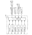
以下、本発明の一実施形態について図面を参照して説明する。図1に示した車両用灯具の配光制御システムは、ランプ群10の配光を配光制御回路20により制御するものであり、車両に搭載されたナビゲーション(経路誘導)システム30を一部兼用して構成されている。
【0008】
ランプ群10は、車両の前部に付設されたヘッドランプ、フォグランプ、コーナーランプなどの複数のランプにより構成されて車両前方から側方を照射するものであり、各ランプの光軸方向、照射範囲、又は光量などの変化によって全体の配光を変化させられるようになっている。配光制御回路20は、ナビゲーションシステム30のナビ制御回路31から出力された指示信号に従いランプ群10の配光を制御する。
【0009】
ナビゲーションシステム30は、それぞれメイン制御回路31に接続された入出力部32、地図データベース33、GPS受信器34、方位センサ35、車速センサ36、及びVICS受信器37を備えている。入出力部32は、目的地の指示時などに運転者により操作されるとともに、運転者に対し必要な案内情報を画面表示又は音声により出力するものである。地図データベース33は、道路の位置及び形状を複数のノード(節点)及び該各ノードを結ぶ複数のリンク(線分)により記憶したものである。
【0010】
GPS(Global Positioning System)受信器34は、GPS衛星から発信された車両の現在位置を表すGPS信号を受信するものである。方位センサ35は、車両の向いている方向を検出するものである。車速センサ36は、車両の速度を検出するものである。VICS(Vehicle Information & Communication System)受信器37は、FM多重、電波ビーコン、光ビーコンなどによる路車間通信によって、車両の走行路の交通量などの道路交通情報を表すVICS信号を受信するものである。
【0011】
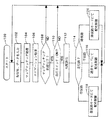
メイン制御回路31は、入出力部32における運転者による指示操作、地図データベース33に記憶されている地図データ、GPS及びVICS受信器34,37により受信されたGPS及びVICS信号、並びに各センサ35,36による検出に基づき図2に示したフローチャートに対応したプログラムを実行し、ナビゲーションシステムとしての処理を行うとともに、ランプ群10の配光を決定して配光制御回路20に対し指示信号を出力するものである。また、メイン制御回路31には、ランプ群10の点灯を指示するための点灯スイッチ41、及び前記エンジンのスロットルバルブの開度を検出するスロットル開度センサ43も接続されている。
【0012】
次に、上記のように構成した配光制御システムの動作を図2のフローチャートに沿って説明する。最初、図示しない車両のイグニッションスイッチがオン操作されると、メイン制御回路31は、ステップ100にてプログラムの実行を開始し、以後、ステップ102〜120からなる循環処理を繰返し実行し続ける。
【0013】
メイン制御回路31は、まず、ステップ102にて、上記運転者の指示操作を表す信号、地図データ、GPS及びVICS信号、並びに各検出信号をそれぞれ入力する。そして、ステップ104にて、マップマッチング処理を実行する。マップマッチング処理とは、上記入力したGPS信号及び各検出信号に基づいて車両の現在位置を算出し、同算出した現在位置を地図データと整合させることにより、地図データにより表されるいずれかの道路上に車両の現在位置を特定する処理である。なお、同処理は、プログラムの進行を止めることなく上記循環処理中に繰返し実行されるものであり、算出した車両の現在位置が地図データと整合せず地図データにより表される道路上に車両の現在位置を特定できなかった場合にも、同処理を未完のままプログラムは次のステップ106以降へ進められるようになっている。
【0014】
ステップ106においては、マップマッチング処理により特定された車両の現在位置、並びに上記入力された運転者の指示操作を表す信号、地図データ、及びVICS信号に基づいて、車両の目的地までの経路を算出して運転者に対し案内するなど、ナビゲーションシステムとしての処理(ナビゲーション処理)を実行する。
【0015】
ステップ108においては、マップマッチング処理が完了しているか否かを判定する。このとき、マップマッチング処理が未完であった場合、すなわち算出した車両の現在位置が地図データと整合せず地図データにより表される道路上に車両の現在位置を特定できていなかった場合、メイン制御回路31は、「NO」との判定のもとにプログラムをステップ102へ戻す。一方、このときマップマッチング処理が完了していれば、メイン制御回路31は「YES」との判定のもとにプログラムをステップ110以降へ進める。
【0016】
ステップ110においては、点灯スイッチ41がオン状態であるか否かを判定する。このとき、運転者によってランプ群10の点灯が指示されておらず点灯スイッチ41がオフ状態であれば、メイン制御回路31は「NO」と判定してプログラムをステップ102へ戻す。一方、このとき運転者によってランプ群10の点灯が指示されていて点灯スイッチ41がオン状態であれば、メイン制御回路31は、「YES」と判定してプログラムをステップ112以降へ進めて配光制御のための処理を開始する。
【0017】
ステップ112においては、車速センサ36により検出した車速及びスロットル開度センサ43により検出した前記エンジンのスロットルバルブの開度の相互関係を車両の基本出力マップと比較することにより、車両の走行路の勾配を算出する。ステップ114においては、同算出した勾配に基づいて、車両の走行路が殆ど勾配のない平坦路であるか、登坂路であるか、又は降坂路であるかを判定し、プログラムを分岐させる。
【0018】
走行路が平坦路であると判定した場合、メイン制御回路31は、ステップ116にて通常モードによる配光制御を実行する。この処理は、具体的には次のようにして実行される。
【0019】
まず、前記ステップ104のマップマッチング処理により特定された車両の現在位置と車速センサ36により検出した車速とに基づいて、図3(a)に示したように、地図データベース33に記憶されている道路上に車両の所定時間(例えば、2.5秒)後の予測位置を特定する。そして、車両の進行に伴いその予測位置を随時更新しながら、その予測位置が配光の変更制御を必要とする地点に達したか否かを繰り返し判定し続ける。ここで、配光の変更制御が必要な地点とは、例えば、直線道路からカーブに差し掛かる地点若しくはカーブから直線道路に抜け出る地点などの道路形状が変化する地点、又は交差点、又は予め地図データベース33の地図データ上にて定義された車両の走行区域(例えば、市街地、郊外、高速道路など)が切り換わる地点などである。
【0020】
ただし、この処理は、プログラムの進行を止めることなく、上記ステップ102〜120からなる循環処理中に繰返し実行されるものである。新たに特定した予測位置が上記の要配光変更制御地点に達していなかった場合には、配光の変更制御を実行することなくそのまま一旦プログラムをステップ102へ戻し、次回の同ステップ116の実行時に予測位置を更新した上で再び同様の判定を行うようにする。この繰り返しにより、メイン制御回路31は車両の予測位置が要配光変更制御地点に達するのを待つ。
【0021】
上記循環処理中、予測位置が要配光変更制御地点に達した場合、メイン制御回路31は同地点に対して適切な配光を決定し、同決定した配光を指示する信号を配光制御回路20に対し出力する。これに応じて、配光制御回路20はランプ群10を制御して配光を切り換える。
【0022】
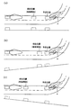
一方、前記ステップ114にて走行路が登坂路であると判定した場合、メイン制御回路31は、ステップ118にて登坂路モードによる配光制御を実行する。同モードにおいても、メイン制御回路31は、予測位置を特定して、同予測位置が要配光変更制御地点に達したとき配光を決定して配光指示信号を出力するようにするが、この場合、図3(b)に示したように、予測位置を、前記ステップ116の通常モードによる配光制御時と比較して、車両の現在位置に近い位置、すなわち車両が早く(例えば、1.5秒後)到達する位置に特定する。したがって、この登坂路モードによる配光制御の実行時には、通常モードによる配光制御の実行時と比較して、遅いタイミングでランプ群10の配光が切り換わることになる。
【0023】
一方、前記ステップ114にて走行路が降坂路であると判定した場合、メイン制御回路31は、ステップ120にて降坂路モードによる配光制御を実行する。同モードにおいても、メイン制御回路31は、予測位置を特定して、同予測位置が要配光変更制御地点に達したとき配光を決定して配光指示信号を出力するようにするが、この場合、図3(c)に示したように、予測位置を、前記ステップ116の通常モードによる配光制御時と比較して、車両の現在位置から遠い位置、すなわち車両が遅く(例えば、3.5秒後)到達する位置に特定する。したがって、この降坂路モードによる配光制御の実行時には、通常モードによる配光制御の実行時と比較して、早いタイミングでランプ群10の配光が切り換わることになる。
【0024】
なお、上記各場合において、配光の切り換えは徐々に連続的に行うようにしている。例えばランプ群10の光軸αを左右に振る場合ならば、上記各配光の切り換え開始タイミング後に光軸の振り角αを徐々に大きくすることにより配光を切り換えるようにしている(図3参照)。
【0025】
上述のように、上記実施形態においては、ステップ112にて算出した車両の走行路の勾配に応じて、ステップ116〜120の各モードによる配光制御処理が選択されて配光の切り換えタイミングが調整されるようになっている。したがって、登坂路又は降坂路の走行中に配光の変更を行った場合にも、運転者に対して違和感を与えることが回避される。
【0026】
なお、上記実施形態においては、車両の走行路の勾配を、車速センサ36により検出した車速及びスロットル開度センサ43により検出した前記エンジンのスロットルバルブの開度の相互関係を車両の基本出力マップと比較することにより算出するようにしたが、これに代えて、図1にて二点鎖線により示したように、車両の勾配を検出する勾配センサ44を別途設けて、同勾配センサ44により検出した車両の勾配を走行路の勾配としてステップ112の判定に用いるようにしてもよい。または、地図データベース33に予め道路の勾配情報も記憶しておくようにしてもよい。あるいは、エンジン出力から推定される平坦路での基準加速度と、実際の車両の実加速度との差を算出し、実加速度が基準加速度よりも所定値以上大きい場合には降坂路と判定し、所定値以上小さい場合には登坂路と判定してもよい。
【0027】
また、上記実施形態においては、走行路の勾配に基づいて通常モード、登坂路モード、及び降坂路モードの3種類の配光制御を選択的に実行するようにしたが、この配光制御のモード分けは、勾配の大小に応じてさらに細分化するようにしてもよい。また、勾配の大きさから前記予測位置を直接決定するようにして、勾配の大小に応じて配光の切り換えタイミングを任意に調整するようにしてもよい。また、登坂路モード及び降坂路モードのうちの一方を省略して、上記登坂路走行時の制御及び降坂路走行時の制御のうちのいずれか一方のみを採用するようにしてもよい。これによっても、本発明による効果を相応に期待することができる。
【図面の簡単な説明】
【図1】本発明の一実施形態に係る車両用灯具の配光制御システムの全体概略図である。
【図2】図1のメイン制御回路にて実行されるプログラムを示すフローチャートである。
【図3】(a)は平坦路走行中における配光の切り換え開始タイミングを表し、(b)は登坂路走行中における配光の切り換え開始タイミングを表し、(c)は降坂路走行中における配光の切り換え開始タイミングを表す説明図である。
【符号の説明】
10…ランプ群、20…配光制御回路、30…ナビゲーションシステム、31…メイン制御回路、33…地図データベース、44…勾配センサ。[0001]
[Industrial application fields]
The present invention relates to a light distribution control system that controls light distribution of a vehicle lamp such as a headlight.
[0002]
[Prior art]
Conventionally, as this type of system, for example, as shown in Japanese Patent Publication No. 7-71908, a map database storing a road map and the current position of the vehicle are specified on the road stored in the map database. Controlling the light distribution of the vehicle lamp attached to the front part of the vehicle according to the current position of the vehicle on the road stored in the map database specified by the vehicle position specifying means And a light distribution control means for controlling the illumination area of the lamp according to the traveling direction of the vehicle or the traveling environment during the traveling of the vehicle, so that the driver's visual field is always favorably secured. Are known.
[0003]
[Problems to be solved by the invention]
However, in the above conventional system, the light distribution control means switches the light distribution when changing the light distribution of the vehicle lamp according to the current position of the vehicle specified by the vehicle position specifying means. Regardless of the slope, it was always performed at a uniform timing. Therefore, if the light distribution is changed while traveling on an uphill or downhill road, the driver feels that switching of the light distribution is too early during traveling on the uphill road, and the light distribution during traveling on the downhill road. I felt that switching was too slow, and I felt uncomfortable about each.
[0004]
SUMMARY OF THE INVENTION
An object of the present invention is to provide a light distribution system for a vehicular lamp that can change a light distribution without giving a sense of incongruity to a driver even when the vehicle is traveling on an uphill road or a downhill road. .
[0005]
A structural feature of the present invention is that a light distribution control system for a vehicle lamp provided with the map database, vehicle position specifying means, and light distribution control means is provided with a gradient detection means for detecting the gradient of the traveling path of the vehicle. When the light distribution control means changes the light distribution of the vehicular lamp, the light distribution switching timing is adjusted according to the gradient of the vehicle travel path detected by the gradient detection means, and the vehicle travel path is an uphill road In such a case, the timing for starting the switching of the light distribution is delayed, and when the traveling path of the vehicle is a downhill road, the timing for starting the switching of the light distribution is advanced. According to this, even when the light distribution is changed during traveling on the uphill road or downhill road, the light distribution switching timing is adjusted according to the gradient of the traveling road of the vehicle. Giving a sense of incongruity.
[0006]
Note that one of the control during traveling on the uphill road and the control during traveling on the downhill road may be omitted, and only one of them may be employed. This also makes it possible to expect the effects of the present invention accordingly.
[0007]
DETAILED DESCRIPTION OF THE INVENTION
Hereinafter, an embodiment of the present invention will be described with reference to the drawings. The vehicle lamp light distribution control system shown in FIG. 1 controls the light distribution of the lamp group 10 by the light
[0008]
The lamp group 10 includes a plurality of lamps such as a head lamp, a fog lamp, and a corner lamp attached to the front portion of the vehicle, and irradiates the side from the front of the vehicle. Alternatively, the entire light distribution can be changed by changing the amount of light. The light
[0009]
The
[0010]
A GPS (Global Positioning System) receiver 34 receives a GPS signal representing the current position of a vehicle transmitted from a GPS satellite. The
[0011]
The
[0012]
Next, the operation of the light distribution control system configured as described above will be described with reference to the flowchart of FIG. Initially, when an ignition switch of a vehicle (not shown) is turned on, the
[0013]
First, in
[0014]
In
[0015]
In
[0016]
In
[0017]
In
[0018]
If it is determined that the traveling road is a flat road, the
[0019]
First, as shown in FIG. 3 (a), the road stored in the map database 33 based on the current position of the vehicle specified by the map matching process in
[0020]
However, this process is repeatedly executed during the cyclic process consisting of the
[0021]
If the predicted position reaches the light distribution change control point during the circulation process, the
[0022]
On the other hand, when it is determined in
[0023]
On the other hand, if it is determined in
[0024]
In each of the above cases, the light distribution is switched gradually and continuously. For example, when the optical axis α of the lamp group 10 is swung to the left and right, the light distribution is switched by gradually increasing the swing angle α of the optical axis after the light distribution switching start timing (see FIG. 3). ).
[0025]
As described above, in the above-described embodiment, the light distribution control processing in each mode of
[0026]
In the above embodiment, the relationship between the vehicle speed detected by the vehicle speed sensor 36 and the throttle valve opening of the engine detected by the
[0027]
Further, in the above embodiment, the three types of light distribution control of the normal mode, the uphill road mode, and the downhill road mode are selectively executed based on the gradient of the traveling road. The division may be further subdivided according to the magnitude of the gradient. Further, the predicted position may be directly determined from the magnitude of the gradient, and the light distribution switching timing may be arbitrarily adjusted according to the magnitude of the gradient. Further, one of the uphill road mode and the downhill road mode may be omitted, and only one of the control during the uphill road traveling and the control during the downhill road traveling may be employed. This also makes it possible to expect the effects of the present invention accordingly.
[Brief description of the drawings]
FIG. 1 is an overall schematic diagram of a light distribution control system for a vehicular lamp according to an embodiment of the present invention.
FIG. 2 is a flowchart showing a program executed by the main control circuit of FIG.
3A shows the light distribution switching start timing while traveling on a flat road, FIG. 3B shows the light distribution switching start timing when traveling on an uphill road, and FIG. 3C shows the light distribution switching timing when traveling on a downhill road. It is explanatory drawing showing the switching start timing of light.
[Explanation of symbols]
DESCRIPTION OF SYMBOLS 10 ... Lamp group, 20 ... Light distribution control circuit, 30 ... Navigation system, 31 ... Main control circuit, 33 ... Map database, 44 ... Gradient sensor.
Claims (3)
車両の現在位置を前記地図データベースに記憶されている道路上にて特定する車両位置特定手段と、
該車両位置特定手段により特定された前記地図データベースに記憶されている道路上の車両の現在位置に応じて車両の前部に付設された灯具の配光を制御する配光制御手段とを備えた車両用灯具の配光制御システムにおいて、
前記車両の走行路の勾配を検出する勾配検出手段を設け、
前記配光制御手段は、前記車両用灯具の配光を変更する際、配光の切り換えのタイミングを前記勾配検出手段により検出した車両の走行路の勾配に応じて調整し、前記車両の走行路が登坂路であった場合は前記配光の切り換えを開始するタイミングを遅らせ、前記車両の走行路が降坂路であった場合は前記配光の切り換えを開始するタイミングを早めることを特徴とする車両用灯具の配光制御システム。A map database that stores road maps;
Vehicle position specifying means for specifying the current position of the vehicle on the road stored in the map database;
Light distribution control means for controlling the light distribution of the lamps attached to the front of the vehicle according to the current position of the vehicle on the road stored in the map database specified by the vehicle position specifying means In a light distribution control system for a vehicle lamp,
Provided with a gradient detecting means for detecting the gradient of the traveling path of the vehicle,
The light distribution control means adjusts the light distribution switching timing according to the gradient of the vehicle travel path detected by the gradient detection means when changing the light distribution of the vehicular lamp. When the vehicle is an uphill road, the timing for starting the switching of the light distribution is delayed, and when the traveling path of the vehicle is a downhill road, the timing for starting the switching of the light distribution is advanced. Light distribution control system for lighting equipment.
車両の現在位置を前記地図データベースに記憶されている道路上にて特定する車両位置特定手段と、
該車両位置特定手段により特定された前記地図データベースに記憶されている道路上の車両の現在位置に応じて車両の前部に付設された灯具の配光を制御する配光制御手段とを備えた車両用灯具の配光制御システムにおいて、
前記車両の走行路の勾配を検出する勾配検出手段を設け、
前記配光制御手段は、前記車両用灯具の配光を変更する際、配光の切り換えのタイミングを前記勾配検出手段により検出した車両の走行路の勾配に応じて調整し、前記車両の走行路が登坂路であった場合には前記配光の切り換えの開始するタイミングを、平坦路と比べて遅らせることを特徴とする車両用灯具の配光制御システム。A map database that stores road maps;
Vehicle position specifying means for specifying the current position of the vehicle on the road stored in the map database;
Light distribution control means for controlling the light distribution of the lamps attached to the front of the vehicle according to the current position of the vehicle on the road stored in the map database specified by the vehicle position specifying means In a light distribution control system for a vehicle lamp,
Provided with a gradient detecting means for detecting the gradient of the traveling path of the vehicle,
The light distribution control means adjusts the light distribution switching timing according to the gradient of the vehicle travel path detected by the gradient detection means when changing the light distribution of the vehicular lamp. When the vehicle is an uphill road, the light distribution control system for a vehicular lamp is characterized in that the light distribution switching start timing is delayed as compared with a flat road.
車両の現在位置を前記地図データベースに記憶されている道路上にて特定する車両位置特定手段と、
該車両位置特定手段により特定された前記地図データベースに記憶されている道路上の車両の現在位置に応じて車両の前部に付設された灯具の配光を制御する配光制御手段とを備えた車両用灯具の配光制御システムにおいて、
前記車両の走行路の勾配を検出する勾配検出手段を設け、
前記配光制御手段は、前記車両用灯具の配光を変更する際、配光の切り換えのタイミングを前記勾配検出手段により検出した車両の走行路の勾配に応じて調整し、前記車両の走行路が降坂路であった場合には前記配光の切り換えの開始するタイミングを、平坦路と比べて早めることを特徴とする車両用灯具の配光制御システム。A map database that stores road maps;
Vehicle position specifying means for specifying the current position of the vehicle on the road stored in the map database;
Light distribution control means for controlling the light distribution of the lamps attached to the front of the vehicle according to the current position of the vehicle on the road stored in the map database specified by the vehicle position specifying means In a light distribution control system for a vehicle lamp,
Provided with a gradient detecting means for detecting the gradient of the traveling path of the vehicle,
The light distribution control means adjusts the light distribution switching timing according to the gradient of the vehicle travel path detected by the gradient detection means when changing the light distribution of the vehicular lamp. When the vehicle is a downhill road, the light distribution control system for a vehicular lamp is characterized in that the timing for starting the switching of the light distribution is advanced compared to a flat road.
Priority Applications (1)
| Application Number | Priority Date | Filing Date | Title |
|---|---|---|---|
| JP2001329364A JP4031925B2 (en) | 2001-10-26 | 2001-10-26 | Light distribution control system for vehicular lamp |
Applications Claiming Priority (1)
| Application Number | Priority Date | Filing Date | Title |
|---|---|---|---|
| JP2001329364A JP4031925B2 (en) | 2001-10-26 | 2001-10-26 | Light distribution control system for vehicular lamp |
Publications (2)
| Publication Number | Publication Date |
|---|---|
| JP2003127756A JP2003127756A (en) | 2003-05-08 |
| JP4031925B2 true JP4031925B2 (en) | 2008-01-09 |
Family
ID=19145278
Family Applications (1)
| Application Number | Title | Priority Date | Filing Date |
|---|---|---|---|
| JP2001329364A Expired - Fee Related JP4031925B2 (en) | 2001-10-26 | 2001-10-26 | Light distribution control system for vehicular lamp |
Country Status (1)
| Country | Link |
|---|---|
| JP (1) | JP4031925B2 (en) |
-
2001
- 2001-10-26 JP JP2001329364A patent/JP4031925B2/en not_active Expired - Fee Related
Also Published As
| Publication number | Publication date |
|---|---|
| JP2003127756A (en) | 2003-05-08 |
Similar Documents
| Publication | Publication Date | Title |
|---|---|---|
| US6752508B2 (en) | Headlamp system for vehicle | |
| US8843292B2 (en) | Adaptive speed control device | |
| JP5397452B2 (en) | Driving assistance device | |
| US20090005929A1 (en) | Vehicle behavior learning apparatuses, methods, and programs | |
| JPH10166934A (en) | Lamp device for vehicle | |
| JP2008275575A (en) | Vehicle behavior learning device and program | |
| JP2002052975A (en) | Headlamp system for vehicle | |
| JP2009255639A (en) | Automatic lighting device for vehicle | |
| JPH1139592A (en) | Vehicle travel control device | |
| JP4978439B2 (en) | Vehicle travel support device | |
| JP6870735B2 (en) | Direction indicator control method and direction indicator control device | |
| JP4235380B2 (en) | Light distribution control system for vehicular lamp | |
| JP4031925B2 (en) | Light distribution control system for vehicular lamp | |
| JP4181770B2 (en) | Light distribution control system for vehicular lamp | |
| JP4131790B2 (en) | Light distribution control system for vehicular lamp | |
| JP2002181579A (en) | Vehicle navigation device | |
| JP2010190673A (en) | Apparatus for change of specification for vehicle | |
| JPH09288797A (en) | Speed controller for vehicle | |
| JP2008100682A (en) | Light distribution control system for vehicular lamp | |
| JP2008250871A (en) | Vehicle driving warning device | |
| JP4130870B2 (en) | Light distribution control system for vehicular lamp | |
| JP4127997B2 (en) | Light distribution control system for vehicular lamp | |
| JP2004347070A (en) | Apparatus for controlling vehicle | |
| JP4518667B2 (en) | Light distribution control system for vehicular lamp | |
| JPH11321441A (en) | Automotive headlight control system |
Legal Events
| Date | Code | Title | Description |
|---|---|---|---|
| A621 | Written request for application examination |
Free format text: JAPANESE INTERMEDIATE CODE: A621 Effective date: 20041022 |
|
| A977 | Report on retrieval |
Free format text: JAPANESE INTERMEDIATE CODE: A971007 Effective date: 20070927 |
|
| TRDD | Decision of grant or rejection written | ||
| A01 | Written decision to grant a patent or to grant a registration (utility model) |
Free format text: JAPANESE INTERMEDIATE CODE: A01 Effective date: 20071002 |
|
| A61 | First payment of annual fees (during grant procedure) |
Free format text: JAPANESE INTERMEDIATE CODE: A61 Effective date: 20071022 |
|
| R150 | Certificate of patent or registration of utility model |
Free format text: JAPANESE INTERMEDIATE CODE: R150 |
|
| FPAY | Renewal fee payment (event date is renewal date of database) |
Free format text: PAYMENT UNTIL: 20101026 Year of fee payment: 3 |
|
| FPAY | Renewal fee payment (event date is renewal date of database) |
Free format text: PAYMENT UNTIL: 20101026 Year of fee payment: 3 |
|
| FPAY | Renewal fee payment (event date is renewal date of database) |
Free format text: PAYMENT UNTIL: 20111026 Year of fee payment: 4 |
|
| LAPS | Cancellation because of no payment of annual fees |