JP4030272B2 - Liquid cooling method and apparatus for glassware mold - Google Patents
Liquid cooling method and apparatus for glassware mold Download PDFInfo
- Publication number
- JP4030272B2 JP4030272B2 JP2001102098A JP2001102098A JP4030272B2 JP 4030272 B2 JP4030272 B2 JP 4030272B2 JP 2001102098 A JP2001102098 A JP 2001102098A JP 2001102098 A JP2001102098 A JP 2001102098A JP 4030272 B2 JP4030272 B2 JP 4030272B2
- Authority
- JP
- Japan
- Prior art keywords
- mold
- liquid coolant
- manifold
- crankshaft
- mold part
- Prior art date
- Legal status (The legal status is an assumption and is not a legal conclusion. Google has not performed a legal analysis and makes no representation as to the accuracy of the status listed.)
- Expired - Fee Related
Links
- UHOVQNZJYSORNB-UHFFFAOYSA-N c1ccccc1 Chemical compound c1ccccc1 UHOVQNZJYSORNB-UHFFFAOYSA-N 0.000 description 1
Images


Classifications
-
- C—CHEMISTRY; METALLURGY
- C03—GLASS; MINERAL OR SLAG WOOL
- C03B—MANUFACTURE, SHAPING, OR SUPPLEMENTARY PROCESSES
- C03B9/00—Blowing glass; Production of hollow glass articles
- C03B9/30—Details of blowing glass; Use of materials for the moulds
- C03B9/38—Means for cooling, heating, or insulating glass-blowing machines or for cooling the glass moulded by the machine
- C03B9/3875—Details thereof relating to the side-wall, body or main part of the moulds
-
- C—CHEMISTRY; METALLURGY
- C03—GLASS; MINERAL OR SLAG WOOL
- C03B—MANUFACTURE, SHAPING, OR SUPPLEMENTARY PROCESSES
- C03B9/00—Blowing glass; Production of hollow glass articles
- C03B9/30—Details of blowing glass; Use of materials for the moulds
- C03B9/34—Glass-blowing moulds not otherwise provided for
- C03B9/353—Mould holders ; Mould opening and closing mechanisms
- C03B9/3532—Mechanisms for holders of half moulds moving by rotation about a common vertical axis
Description
【0001】
【発明の属する技術分野】
本発明は、ガラス製品成形機の金型の冷却技術に関し、より詳しくは、個別セクション機械のブランク型(blank mold)および/または仕上型(blow mold)の液体冷却技術に関する。
【0002】
【従来の技術】
ガラス容器製造術は、現在では、いわゆる個別セクション機械により受け持たれている。このような機械は複数の別々のすなわち個々の製造セクションを有し、各セクションは、溶融ガラスの1つ以上のチャージすなわちゴブを中空ガラス容器に変換しかつ該容器を機械セクションの連続ステーションを通して搬送するための多数の作動機構を有している。各機械セクションは、吹込み作業または絞り作業によりガラスゴブが最初に形成される1つ以上のブランク型と、ブランク型を、容器が最終形状に吹込み成形される仕上型へと搬送する反転アームと、成形された容器を口板(deadplate)上に取り出すトングと、成形された容器を口板からコンベア上に搬送する搬出機構とを有している。米国特許第4,362,544号には、吹込み−吹込み(blow-and-blow)および絞り−吹込み(press-and-blow)ガラス製品成形方法の両方法に関する背景技術が論じられ、かつ両方法に使用できる電空(electropneumatic)個別セクション機械が開示されている。
【0003】
これまで、ガラス製品成形機のブランク型および仕上型は、一般に、空気を、金型部分に向けまたは金型部分に通すことにより冷却されている。また、このような技術は、周囲の環境の温度および騒音レベルを増大させ、かつ多量のエネルギを消費する。また、空気が、制御された態様で金型部分から熱を除去する能力が低いため生産性が制限され、空気の温度および流量の制御が困難なため工程の安定性および容器の品質が影響を受ける。例えば米国特許第3,887,350号および第4,142,884号には、金型部分の通路に水等の液体を通して除熱を改善させることが提案されている。しかしながら、液体冷却による除熱は急激過ぎるため、少なくとも金型の或る領域では制御できず、従って、金型部分の内面すなわち成形面から、液体冷却通路が設けられる金型外周部への熱伝導を低下させる処置を講じなければならない。従来技術において、液体クーラントの除熱をこのように制御する種々の技術が提案されているが、いずれも完全には満足できないものである。
【0004】
本件出願人の所有する1999年9月20日付米国特許出願第09/400,123号には、各金型が熱伝導構造からなる本体を有し、該本体が、溶融ガラスの成形面を備えた中央部と、該中央部から半径方向外方に間隔を隔てた周辺部とを備えた構成の、ガラス製品成形機の成形金型を冷却するシステムおよび方法が開示されている。金型本体の周辺部の回りには、複数のクーラント通路が間隔を隔てて配置され、液体クーラントはこのような通路に通されて、成形面からの伝導により本体から除熱する。成形面から液体クーラント通路への熱伝導を低下させるため、少なくとも幾つかの液体クーラント通路と成形面との間の半径方向部分には、本体内へと軸線方向に延びる複数の開口が設けられている。これらの開口は、成形面の輪郭および他の製造パラメータと関連して、金型本体の一部または全体に亘って或る深さで金型本体内に延びており、成形面からクーラント通路への熱伝導を制御する。これらの開口の全部または一部には、成形面からクーラント通路への熱伝導を一層適合させるための材料を充填できる。金型本体は、高含有量のシリコンおよびモリブデンを有するオーステナイト・ニレジスト延性鋼(austenitic Ni-Resist ductile iron)で作られている。多数のクーラント通路を通るクーラントの流れを制御するための端板が金型本体により支持されている。金型は、ブランク型または仕上型のいずれでもよい。
【0005】
上記米国特許出願に開示のガラス製品成形機の金型冷却システムおよび方法は、問題に対処でき、従って今でも現存するが、更なる改善が望まれている。より詳しくは、金型部分への液体クーラントの配給および金型部分からの液体クーラントの排出を行うためのホース、チューブおよびフィッティングを省略することが望まれている。金型部分からの液体クーラントの流れは高温であり、従って、ガラス製品成形システムの苛酷な環境的作動条件下での、クーラント通路での潜在的な損傷および漏洩を無くすことが強く望まれている。溶融ガラス、尖ったガラス粒子および使用済み潤滑剤は、ハウジング、チューブおよびフィッティングに損傷を引き起こすことがある。ホース、チューブおよびフィッティングは、通常の作動中の苛酷な作動条件および激しい振動力によって緩んだり疲労し、また、金型部分および作動機構の迅速なメインテナンス、補修および交換を妨げる。
【0006】
【発明が解決しようとする課題】
従って、本発明の広い目的は、全てのクーラント通路が包囲されておりかつガラス製品成形システムの苛酷な作動条件下での摩擦および疲労から保護される構成のガラス製品成形機の金型を冷却するシステムおよび方法を提供することにある。本発明の他の目的は、金型本体が開閉されるときのシステム構成要素間の相対移動に適合する液体クーラント分配/シーリングシステムを提供することにある。
【0007】
【課題を解決するための手段】
簡単に言えば、本発明の好ましいシステムおよび方法は、可撓性ホース等ではなく、包囲形枢動ロータリユニオン構造を介して、ガラス製品成形機のブランク型半部または仕上型半部に液体クーラントを指向させる。クーラントマニホルドは、各枢動金型アームにより支持されかつ各金型部分の下端部でクーラント入口ポートおよびクーラント出口ポートと連通する。マニホルドは、浮動軸シール、ロータリユニオン組立体およびクランクアームにより、クーラント源および関連IS機械セクションのセクションボックス内のクーラント戻り部(coolant return)に連結される。各枢動連結、すなわちセクションボックスとクランクアームとの間、クランクアームとロータリユニオン組立体との間、およびロータリユニオン組立体と浮動軸シールとの間の枢動連結は、液体クーラントを、マニホルドおよび金型部分に供給しかつマニホルドから金型部分へと戻す2方向ロータリユニオンを有している。クーラントマニホルドと金型部分との間、およびクーラントマニホルドと浮動軸シールとの間の動的浮動リングシールは、金型部分が開閉されるときのこれらの構成要素間の相対移動に順応する。
【0008】
より詳しくは、本発明の好ましい実施形態によるガラス製品成形機の金型冷却システムは、互いに近づく方向および離れる方向に移動できるように取り付けられた1対の金型アームと、各金型アームにより支持されかつ互いに協働してガラス製品金型を形成することができる少なくとも1つのブランク型部分または仕上型部分とを有している。各金型部分は、該金型部分の一端で互いに隣接する入口および出口を備えた少なくとも1つのクーラント通路を有する。クーラントマニホルドは、クーラント入口および出口が配置された金型部分の端部に隣接して各金型アームにより支持されており、各マニホルドは、関連金型部分の入口および出口に連結される入口クーラント流路および出口クーラント流路を備えている。クーラント源およびクーラント戻り部が、金型アームに隣接する固定位置に配置され、枢動カップリングロータリユニオン組立体が、クーラント源とマニホルドへの戻り部とを連結している。枢動カップリングロータリユニオン組立体は、クーラントを、クーラント源から、枢動カップリング組立体およびマニホルド入口通路を通して金型部分の金型入口へと指向させ、かつ金型出口から、マニホルド出口通路および枢動カップリング組立体を通してクーラント戻り部に指向させる平行クーラント流路を備えている。
【0009】
本発明の好ましい実施形態による枢動カップリングロータリユニオン組立体は、IS機械のセクションボックスのハウジングに回転可能に連結された第1クランク軸を備えたクランクアーム組立体、第2クランク軸、および第1クランク軸と第2クランク軸とを相互連結するクランクタイバーを有している。第2クランク軸は、マニホルドの側壁に固定されたヘッドを備えたマニホルドタイシャフトと同様に軸リンクブロック内に回転可能に受け入れられている。セクションボックスハウジングおよび軸リンクブロック内のシールは、第1および第2クランク軸およびマニホルドタイシャフトを包囲している。平行クーラント通路が、セクションボックスから、第1クランク軸を通り、クランクタイバーを横方向に通り、第2クランク軸を通り、軸リンクブロックを横方向に通り、更にマニホルドタイシャフトおよびヘッドを通って、金型アーム上のクーラントマニホルドへと延びている。本発明の好ましい実施形態による他の特徴によれば、軸リンクブロック、第2および第1クランク軸および相互連結クランクタイバーに排出通路が形成され、該排出通路は、関連軸と係合するシール間の各軸に開口して、シールを通って漏洩することがあるあらゆるクーラントを重力により排出する。
【0010】
本発明の他の態様とは別に使用するか、組み合わせて使用できる本発明のもう1つの態様によれば、金型部分は、各金型部分の下端部の半径方向棚部と選択的に係合するクランプにより、関連金型アームに解放可能に固定される。各クランプは、金型アーム上の固定位置に支持されたブリッジと、金型部分の棚部に載るか、通り越えるように選択的に回転すべくブリッジの下に支持されたロックダウンクリップとを有している。かくして、ロックダウンクリップは、金型部分の棚部上に載って金型部分の棚部を金型アーム上に保持する位置に回転されるか、作業者が補修または交換のために金型部分を容易に取り外すことができるように、金型部分の棚部を通り越えることができる。ロックダウンクリップとブリッジとの間の戻り止めロック構造は、ロックダウンクリップの棚部載置位置または棚部通り越え位置でのロックダウンクリップの解放可能ロッキングを行う。ロッドは、好ましくは、クリップから、金型部分に平行なブリッジの開口を通って金型部分の上縁部に隣接する位置へと延び、ロックダウンクリップの、金型部分との係合位置および係合解除位置への回転を容易にする。金型アームのピンは、金型部分の下面に設けられた開口内に受け入れられて、金型アームが一体化されるときに対向金型部分の自動調節が行えるように金型部分の制限された回転を可能にする。
【0011】
【発明の実施の形態】
本発明およびその目的、特徴および長所は、以下の記載、特許請求の範囲の記載および添付図面から最も良く理解されよう。
【0012】
本件出願人の所有する上記1999年9月20日付米国特許出願第09/400,123号は、背景技術の目的で本願に援用する。
【0013】
図1および図2は、本発明の好ましい実施形態によるクーラント配給システム32が設けられた個別セクションガラス製品成形機の1つのセクションの仕上型ステーション30の一部を示す。静止支軸38には1対の金型アーム34、36が枢着されており、各金型アーム34、36には複数の金型部分40が支持されている。各金型部分40は、対向アームに支持された対向金型部分と協働して、ガラス製品を成形するための金型キャビティを形成する。好ましい実施形態は仕上型ステーション30に関連したものが図示されており、該仕上型ステーション30では、金型部分30の各対が、底金型要素42と協働して仕上型キャビティを形成する。しかしながら、本発明によるクーラント配給システム32は、リニア機械であるかロータリ機械であるかを問わず、IS機械セクションのブランク型ステーションでのブランク型の冷却にも等しく有効であることを理解されたい。金型アーム34に関連するクーラント配給システム32(図1)を詳細に説明する。金型アーム36に関連するクーラント配給システムは、システム32と鏡像関係をなしている。また、図1および図2には、ステーション30が、3対の金型部分40を備えたいわゆるトリプルゴブIS機械用ステーションとして示されているが、本発明は、いわゆるシングル、ダブル、クウォッド形および他の形式のガラス製品成形機にも等しく有効である。
【0014】
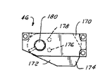
金型アーム34と連動できるように、クーラントマニホルド44が金型アーム34の下に固定されている。マニホルド44により複数のクランプ46が支持されており、各クランプ46は、関連する金型部分40をマニホルドに対して所定位置に固定する。各クランプ46はブリッジ170(図1および図2、および図17〜図20)を有し、該ブリッジ170は、マニホルド44に固定された側方脚と、マニホルドの反対側の面に対して平行に該面から間隔を隔てた上方リーチとを備えている。各ブリッジ170の下には、ロックダウンクリップ172が配置されている。各クリップ172は本体を有し、該本体は、各金型部分40の下端部から横方向外方に延びている板148(図1および図2)により形成された棚部の上に載るように組み立てられる、横方向に延びたフィンガ174を備えている。ブリッジ170の下面には、1対のポケット176、178が形成されている。ロッド180は、この下端部に嵌合、ピン止めまたは他の方法で固定されたラグ182を有している。ロッド180は、関連する金型部分40に隣接する金型アーム34または36を通って上方に延びている。各ロッド180の上端部には、適当な工具と係合できる六角ヘッドが設けられている。ラグ182のラジアルローブには、嵌合その他の方法で位置合せピン184が固定されており、該位置合せピン184は、前記ローブからロッド180に対して平行に上方に延びていて、後述のようにしてブリッジ170のポケット176、178と選択的に整合する。
【0015】
ラグ182およびロッド180の下端部は、クリップ172の本体のポケット186内に配置される。スプリング188は、ラグ182の下のポケット内に圧縮された状態で捕捉されている。ロッド180と同軸状に、ピン190がクリップ172から下方に延びており、該ピン190は、マニホルド44の対応ポケット内に受け入れられてクリップ172の回転を案内する。ラグ182のローブは、クリップ172をロッド170に対して回転可能に連結する。すなわち、ロッド180は時計回り方向(図1図2および図17〜図20)に回転されて、位置合せピン184がブリッジ170の位置合せポケット176整合するまでロックダウンクリップ172を時計回り方向に回転させ、この時点で、スプリング188の力によってピン184がポケット176内に押し込まれる。この時点で、クリップ172のアーム174が、関連する金型本体40の板148を通り越え、これにより作業者は、補修または交換のために金型本体を金型ステーションから持ち上げることができる。金型本体がマニホルド44上の位置合せピン69(図2)上の所定位置で交換されると、ロッド180およびロックダウンクリップ172は、ボールピン184がブリッジ170の位置合せポケット178と整合するまで反時計回り方向に回転され、この時点で、フィンガ174が金型板148上に載り、金型を所定位置に保持する。図1において、第1金型部分と関連するクランプ46は、金型部分を解放する非係合位置にあるところが示されており、一方、第2および第3金型部分と関連するクランプ46は係合位置にあるところが示されている。ロッド180およびピン190は、クリップ172をブリッジ170の下の所定位置に保持する機能も有している。
【0016】
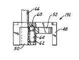
図21および図22は、変更態様のロックダウンクランプ192を示す。各クランプ192は、ブリッジ48を有し、該ブリッジ48は、マニホルド44に固定された側方脚と、マニホルドの反対側の面に対して平行に該面から間隔を隔てた上方リーチとを備えている。各ブリッジ48の下には、ロックダウンクリップ50が配置されている。各クリップ50は本体を有し、該本体は、各金型部分40の下端部から横方向外方に延びている板148の上に載るように組み立てられる、横方向に延びたフィンガ52を備えている。ブリッジ48の下面には、1対のポケット56、58が形成されている。位置合せボール60およびコイルスプリング62は、ロックダウンクリップ50の本体のポケット64内に圧縮された状態で捕捉されており、ブリッジ48の下面のポケット56、58と選択的に整合する。各ロックダウンクリップ50の本体にはクリップロッド66が連結されており、該クリップロッド66は、ロックダウンクリップの本体から金型アーム34または36を通って上方に延び、クリップ50およびクリップフィンガ52を選択的に回転させて、関連する隣接金型部分の棚部54との係合および係合解除を行う。すなわち、ロッド66は時計回り方向に回転されて、位置合せボール60がブリッジ48の位置合せポケット56と整合するまで、ロックダウンクリップ50を時計回り方向に回転させる。この時点で、クリップ50のフィンガ52が、関連する金型本体40の板148を乗り越え、これにより作業者は、補修または交換のために金型本体を金型ステーションから持ち上げることができる。金型本体がマニホルド44上の位置合せピン69(図2)上の所定位置で交換されると、ロッド66およびロックダウンクリップ50は、位置合せボール60がブリッジ48の位置合せポケット58と整合するまで反時計回り方向に回転され、この時点で、脚52が金型板148上に載り、金型を所定位置に保持する。
【0017】
クーラント配給システム32は更に、ロータリユニオン組立体68(図1および図3〜図5)を有し、該ロータリユニオン組立体68は、各機械セクションでセクションボックス70の開口内に挿入できるセクションボックスハウジング72を備えている。セクションボックスハウジング72は、頂パネル74と、該パネル74の下面に溶接その他の方法で固定されたブロック76とを有している。ブロック76は、クランクアーム組立体82の下方クランク軸80を受け入れるための、パネル74の開口78(図3)と整合する中央開口を有している。軸80は、ベアリングカバー板86により閉じられた、軸線方向に間隔を隔てて配置されたベアリング84(図4)によりブロック76内に支持される。軸線方向に間隔を隔てた複数のシール88がブロック76の内径面に形成された対応チャンネル内に取り付けられ、該シール88は、軸80の対面ランドとシール係合する。1対のポート90、92がブロック76を通って横方向に延び、かつ中央シール88の横方向対向面上で、ブロック76の内部ボアに開口している。排出ポート94が、ブロック76内へと横方向に延び、かつ2つの下方シール88間でブロックの中央ボアに開口している。各シール88は、関連軸と摺動係合するTeflon(商標)ベース環状ロータリシール88aと、およびエラストマОリング88bとからなる。Оリング88bは、シール88aを半径方向内方に圧縮し、かつ関連シール溝の基部との半径方向外方のシール係合を行う。
【0018】
クランクアーム組立体82(図3〜図5および図15)は、第1クランク軸すなわち下方クランク軸80および第2クランク軸すなわち上方クランク軸96を有し、両クランク軸80、96は、クランクタイバー98の反対側端部から反対平行軸線方向に延びている。下方および上方のクランク軸80、96は本質的に同じである。各クランク軸は1対の水通路100、102を有し、該通路はクランク軸の中間部を通って軸線方向に延びかつクランク軸の端部に隣接して横方向外方に開口している。小径の第3通路104が各クランク軸の中間部を通って軸線方向に延びており、かつクランク軸から横方向外方に開口している。下方クランク軸80の通路100と関連する開口および周方向チャンネルはブロック76(図4)のポート90と整合し、かつ通路102の横方向開端部および関連周方向チャンネルはブロック76のポート92と整合する。組み立てられたとき、通路104の横方向開口はブロック76の排出ポート94と整合する。クランクタイバー98内には1対の長手方向平行通路106、107があり(図4、図9および図15)、該通路106、107は、組み立てられたときに、それぞれ、下方クランク軸80の上端部の通路100、102の横方向開口および上方クラウン軸96の下端部の関連通路と整合する。同様に、クランクタイバー98には通路108が設けられており、該通路108は、上下のクランク軸96、80の排出通路104の関連端部を相互連結する。種々の通路の端部の整合およびシーリングを維持するため、クランク軸80、96の端部は、圧嵌め、締り嵌めまたは他の方法でクランクタイバー98に固定される。すなわち、クランク軸80、96はタイバー98の対応開口内で回転しない。
【0019】
軸リンクブロック110は、上方クランク軸96の上端部およびマニホルドタイシャフト112の下端部を回転可能に受け入れる。軸リンクブロック110は1対の平行通路114、116(図4および図9)を有し、該通路114、116は、上方クランク軸96の平行流体通路100、102と、タイシャフト112の対応平行流体通路(該流体通路は、理解を容易にするため同じ参照番号100、102で示されている)とを相互連結する。同様に、上方クランク軸96の排出通路104は軸リンクブロック110の横方向排出通路118と整合され、該通路118は、軸リンクブロックの長手方向排出通路120に連結される。軸リンクブロック110の排出通路118、120は、軸リンクブロックのシール88の上方対と下方対との間で開口していて、シールを通って漏洩することがあるあらゆるクーラントを収集する。タイシャフト112には排出通路は全く存在しない。シール88は上方クランク軸96およびリンクブロック110のタイシャフト112を包囲し、各軸は、関連ベアリングカバー86を備えた、互いに間隔を隔てたローラベアリング84により支持される。リンクブロック110の平行通路114、116は中間シール99の両側に開口しており、軸96、112の平行通路100、102は、前述のように、中央シールの両側の対応軸線方向位置に開口している。
【0020】
タイシャフト112は、この上端部に形成された拡大一体ヘッド122(図3〜図7)を有している。ヘッド122はマニホルド44の側断面図である。壁に固定される。タイシャフト112の通路100、102は、ヘッド122内で、それぞれ、1対の横方向開口すなわちポート124、126に終端している。タイシャフト112の長手方向寸法に対して垂直方向または軸線方向に互い違いに配置されたこれらの開口は、組み立てられたときに、マニホルド44の対向側壁壁の1対の開口すなわちポート128、130と整合する。これらの開口128、130はマニホルドの外面で周方向に拡大されており、1対のОリング132(図3および図7)が各開口128、130の周囲の座ぐりポケット内に配置される。Оリング132がヘッド122とマニホルド44との対向面間で圧縮されるように、1対のねじ134がタイシャフトヘッド122を緩く固定する。Оリングシールに連結される開口128、130の周方向寸法が拡大されていること、およびヘッド122がマニホルドに緩く取り付けられていることにより、金型が開閉されるときに、クーラント開口間の連通を喪失することなくすなわちクーラント開口の周囲のシールを喪失することなく、タイシャフトヘッドとマニホルドとの間の相対移動が可能になり、かくしてマニホルドの側面との浮動軸シールが形成される。
【0021】
マニホルド開口128、130は、マニホルド44の本体内で、マニホルドの本体を通って延びている1対の長手方向平行クーラント通路136、138と連通する(図9〜図14)。マニホルド44上の各金型取付け位置(図示の実施形態では3つの位置)で、1対の側方通路140、142がそれぞれの長手方向クーラント通路136、138から延び、かつマニホルド44の上面で1対の隣接上向き開口クーラントポート144、146に終端している。各金型本体40はこの下端部に取り付けられた板148を有している(図8、図9および図16)。各板148は、組み立てられたときにマニホルド44の開口144、146と整合する1対のクーラント開口150、152を有している。上記係属中の米国特許出願に開示されているように、下方板148は上方板155と協働して、クーラントを、金型本体40の周囲の複数の通路154(図16)を通るように導く。上方板155には、金型本体のクーラント通路154の流体流れの有効断面を調節するための流れアジャスタニードル156が取り付けられている。これは、種々の金型本体間のクーラント流れをバランスさせることを補助し、かつ金型本体および関連クーラント通路の熱伝導特性に適合させることができる。マニホルド44と、該マニホルドに取り付けられた幾つかの金型本体40との間には、摩耗板158が配置されている。板148の下方開口150、152は、関連Оリング159を受け入れるべく、拡大されかつ座ぐりされている。Оリング159に連結される開口150、152の寸法が拡大されているため、金型が開平されるときに、金型本体40と、下に配置された摩耗板と、マニホルドとの間の制限された移動を可能にすると同時に、これらの間のシールされた流体連通を維持できる。
【0022】
かくして、セクションボックス70での流体クーラント源から、ロータリユニオン組立体68(セクションボックスハウジング72、クランクアーム組立体82、軸リンクブロック110およびマニホルドタイシャフト112)およびマニホルド44を通って各金型本体に至り、次に、各金型本体からマニホルド44およびロータリユニオン組立体68を通ってセクションボックス70に戻る流体クーラント循環のための連続経路が形成される。図9を参照してより詳しく説明すると、セクションボックスハウジング72のポート90から、下方クランク軸80の通路100、クランクタイバー98の通路107、上方クランク軸96の通路100、軸リンクブロック110の通路114、タイシャフト112の通路100、およびマニホルド44の通路136を通って金型本体44のクーラント通路154に至る連続経路が存在する。図9には金型本体を通る2つのクーラント通路が示されているが、上記係属中の米国特許出願に開示されているように多数の通路を設けることもできる。次に、金型本体44の通路から、マニホルド44の通路138タイシャフト112の通路102、軸リンクブロック110の通路116、上方クランク軸96の通路102、クランクタイバー98の通路106、下方クランク軸80の通路102およびセクションボックスハウジング72の通路92を通る連続戻り流路が存在する。同様に、軸リンクブロック110の通路120、118から、上方クランク軸96の通路104、クランクタイバー98の通路108および下方クランク軸80の通路104を通ってセクションボックスハウジング72のポート94に至る排出流体の連続流路が存在する。ポート90は、着脱可能な導管160を介してポンプ162に連結され、ポート92は、着脱可能な導管164を介してサンプ166に連結されている。排出ポート94は、着脱可能な導管167により、覗き窓モニタ168を通ってサンプ66に連結されている。
【0023】
以上、前述の全ての目的を完全に満足できるガラス製品成形機の金型を冷却するシステムおよび方法を開示した。クーラント流路は完全に包囲されており、従って、外部ホース、チューブおよびフィッティングの使用に付随する破裂、クラッキングおよび疲労の問題を無くすことができる。クランクアーム組立体とマニホルドとの間およびマニホルドと金型との間の流路継手は摺動シール構造を有し、従って、金型の開閉時にこれらの要素の相互の移動に容易に対応できる。本願に開示したロックダウンクランプ構造は、メインテナンスおよび補修のために冷却システムからの金型本体の分解および再組立てが迅速に行え、かつ金型の開閉時の金型本体相互の小さい移動および取付け構造に対する小さい移動に対応できる。幾つかの変更が示唆されており、当業者ならば、上記開示から他の変更も容易に示唆できるであろう。本発明は、特許請求の範囲に記載の精神および広い範囲に包含されるこのようなあらゆる変更を含むものである。
【図面の簡単な説明】
【図1】本発明の好ましい実施形態による仕上型部分を冷却するシステムが設けられた個別セクション機械の仕上型ステーションを示す部分斜視図である。
【図2】図示を容易にするため1つの金型部分を除去した図1の仕上型ステーションを示す部分斜視図である。
【図3】図1および図2に示した仕上型ステーションのクーラント配給装置を示す分解図である。
【図4】図1〜図3のロータリユニオンクーラント配給装置を示す展開断面図である。
【図4A】図4の円4Aで囲んだ部分を示す拡大断面図である。
【図5】図1〜図4のクーラント配給ロータリユニオン組立体を示す斜視図である。
【図6】図5の6−6線に沿う部分断面図である。
【図7】図5の7−7線に沿う部分断面図である。
【図8】図1および図2の仕上型部分を底面方向から見た斜視図である。
【図9】図1〜図3および図4〜図7のクーラント配給システムのクーラント配給および排出構造を示す部分概略図である。
【図10】図1〜図3のクーラント配給マニホルドを示す斜視図である。
【図11】図10のマニホルドを示す側面図である。
【図12】図10のマニホルドを示す平面図である。
【図13】図11の13−13線に沿う断面図である。
【図14】図11の14−14線に沿う断面図である。
【図15】本発明の好ましいクーラント配給システムのクランクアーム小組立体を示す分解側断面図である。
【図16】本発明の好ましい実施形態によるクーラント配給システムの金型部分を示す部分断面図である。
【図17】図1および図2の金型ロックダウン機構を示す断面図である。
【図18】図17のロッククランプ小組立体を示す斜視図である。
【図19】図18のクランプ小組立体を示す分解斜視図である。
【図20】図17の金型ロックダウン機構を示す平面図である。
【図21】図1および図2のシステムの改善された金型ロックダウン機構を示す平面図である。
【図22】図1および図2のシステムの改善された金型ロックダウン機構を示す部分側断面図である。
【符号の説明】
30 仕上型ステーション
32 クーラント配給システム
40 金型部分
44 マニホルド
68 ローラユニオン組立体
70 セクションボックス
72 セクションボックスハウジング
76 ブロック[0001]
BACKGROUND OF THE INVENTION
The present invention relates to a mold cooling technique for a glassware molding machine, and more particularly to a liquid cooling technique for a blank mold and / or a blow mold of an individual section machine.
[0002]
[Prior art]
Glass container manufacturing is now handled by so-called individual section machines. Such machines have multiple separate or individual manufacturing sections, each section converting one or more charges or gob of molten glass into a hollow glass container and transporting the container through a continuous station in the machine section Has a number of operating mechanisms. Each machine section includes one or more blank molds in which the glass gob is initially formed by blowing or squeezing work, and a reversing arm that transports the blank molds to a finishing mold in which the container is blown to the final shape. And a tongue that takes out the molded container onto a dead plate, and a carry-out mechanism that conveys the molded container from the mouth plate onto a conveyor. U.S. Pat. No. 4,362,544 discusses and discusses background art regarding both blow-and-blow and press-and-blow glassware forming methods. An electropneumatic individual section machine that can be used is disclosed.
[0003]
To date, blank molds and finish dies in glassware forming machines are generally cooled by directing air toward or through the mold part. Such technology also increases the temperature and noise level of the surrounding environment and consumes a large amount of energy. In addition, the ability of air to remove heat from the mold part in a controlled manner is low, which limits productivity and makes it difficult to control the temperature and flow rate of air, affecting the stability of the process and the quality of the container. receive. For example, U.S. Pat. Nos. 3,887,350 and 4,142,884 propose improving heat removal by passing a liquid such as water through the passage of the mold part. However, since heat removal by liquid cooling is too rapid, it cannot be controlled at least in a certain area of the mold, and therefore heat conduction from the inner surface of the mold portion, that is, the molding surface, to the outer periphery of the mold where the liquid cooling passage is provided. Measures must be taken to reduce In the prior art, various techniques for controlling the heat removal of the liquid coolant in this way have been proposed, but none of them is completely satisfactory.
[0004]
In US patent application Ser. No. 09 / 400,123, filed Sep. 20, 1999, owned by the Applicant, each mold has a body comprising a heat conducting structure, the body comprising a center with a molten glass molding surface. A system and method for cooling a molding die of a glassware molding machine is disclosed, comprising a portion and a peripheral portion spaced radially outward from the central portion. Around the periphery of the mold body, a plurality of coolant passages are arranged at intervals, and the liquid coolant is passed through such passages to remove heat from the body by conduction from the molding surface. In order to reduce the heat transfer from the molding surface to the liquid coolant passage, at least some of the radial portions between the liquid coolant passage and the molding surface are provided with a plurality of openings extending axially into the body. Yes. These openings extend into the mold body at a depth over part or all of the mold body in relation to the molding surface profile and other manufacturing parameters, and from the mold surface to the coolant passage. Control the heat conduction. All or part of these openings can be filled with a material to better match the heat transfer from the molding surface to the coolant passage. The mold body is made of austenitic Ni-Resist ductile iron with a high content of silicon and molybdenum. An end plate for controlling the flow of coolant through a number of coolant passages is supported by the mold body. The mold may be either a blank mold or a finishing mold.
[0005]
The mold cooling system and method of the glassware molding machine disclosed in the above-mentioned US patent application can address the problem and thus still exists, but further improvements are desired. More specifically, it is desired to omit the hose, tube, and fitting for delivering the liquid coolant to the mold part and discharging the liquid coolant from the mold part. The liquid coolant flow from the mold parts is hot and therefore it is highly desirable to eliminate potential damage and leakage in the coolant passages under the harsh environmental operating conditions of the glassware molding system. . Molten glass, pointed glass particles and used lubricants can cause damage to the housing, tubes and fittings. The hoses, tubes and fittings loosen and fatigue due to severe operating conditions and severe vibration forces during normal operation, and prevent rapid maintenance, repair and replacement of mold parts and actuation mechanisms.
[0006]
[Problems to be solved by the invention]
Accordingly, a broad object of the present invention is to cool the mold of a glassware molding machine in which all the coolant passages are enclosed and protected from friction and fatigue under the severe operating conditions of the glassware molding system. It is to provide a system and method. It is another object of the present invention to provide a liquid coolant dispensing / sealing system that is adapted for relative movement between system components when the mold body is opened and closed.
[0007]
[Means for Solving the Problems]
Briefly, the preferred system and method of the present invention provides liquid coolant to the blank mold half or finish mold half of a glassware molding machine via an enclosed pivot rotary union structure rather than a flexible hose or the like. Orient. The coolant manifold is supported by each pivot mold arm and communicates with the coolant inlet port and the coolant outlet port at the lower end of each mold portion. The manifold is connected by a floating shaft seal, a rotary union assembly and a crank arm to a coolant return in the section box of the coolant source and associated IS machine section. Each pivot connection, i.e., between the section box and the crank arm, between the crank arm and the rotary union assembly, and between the rotary union assembly and the floating shaft seal, includes liquid coolant, manifold and It has a two-way rotary union that feeds the mold part and returns from the manifold to the mold part. The dynamic floating ring seal between the coolant manifold and the mold part and between the coolant manifold and the floating shaft seal accommodates relative movement between these components as the mold part is opened and closed.
[0008]
More specifically, a mold cooling system of a glassware molding machine according to a preferred embodiment of the present invention includes a pair of mold arms mounted so as to be movable toward and away from each other, and supported by each mold arm. And at least one blank mold part or finish mold part capable of cooperating with each other to form a glassware mold. Each mold part has at least one coolant passage with an inlet and an outlet adjacent to each other at one end of the mold part. A coolant manifold is supported by each mold arm adjacent to the end of the mold part where the coolant inlet and outlet are located, and each manifold is connected to the inlet and outlet of the associated mold part. A flow path and an outlet coolant flow path are provided. A coolant source and coolant return are located in a fixed position adjacent to the mold arm, and a pivoting coupling rotary union assembly connects the coolant source and the return to the manifold. The pivot coupling rotary union assembly directs coolant from the coolant source through the pivot coupling assembly and manifold inlet passage to the mold inlet of the mold part, and from the mold outlet to the manifold outlet passage and A parallel coolant flow path is provided that is directed to the coolant return through the pivot coupling assembly.
[0009]
A pivot coupling rotary union assembly in accordance with a preferred embodiment of the present invention includes a crank arm assembly having a first crankshaft rotatably coupled to a housing of a section box of an IS machine, a second crankshaft, and a second crankshaft. A crank tie bar for interconnecting the first crankshaft and the second crankshaft is provided. The second crankshaft is rotatably received in the shaft link block in the same manner as a manifold tie shaft with a head fixed to the side wall of the manifold. Seals in the section box housing and the shaft link block surround the first and second crankshafts and the manifold tie shaft. A parallel coolant passage extends from the section box through the first crankshaft, through the crank tie bar laterally, through the second crankshaft, laterally through the shaft link block, and further through the manifold tie shaft and head, Extends to the coolant manifold on the mold arm. According to other features in accordance with a preferred embodiment of the present invention, a discharge passage is formed in the shaft link block, the second and first crankshafts and the interconnecting crank tie bar, the discharge passage between the seals engaging the associated shaft. Any coolant that opens into the shafts and may leak through the seal is drained by gravity.
[0010]
According to another aspect of the present invention, which can be used separately or in combination with other aspects of the present invention, the mold parts are selectively engaged with the radial shelf at the lower end of each mold part. A mating clamp is releasably secured to the associated mold arm. Each clamp has a bridge supported in a fixed position on the mold arm and a lock-down clip supported under the bridge to selectively rotate to rest on or pass through the mold part shelf. Have. Thus, the lockdown clip can be rotated to a position that rests on the mold part shelf and holds the mold part shelf on the mold arm, or allows the operator to repair or replace the mold part. Can be passed over the shelf of the mold part. A detent lock structure between the lockdown clip and the bridge provides releasable locking of the lockdown clip at the shelf placement position or over the shelf passage of the lockdown clip. The rod preferably extends from the clip through a bridge opening parallel to the mold part to a position adjacent to the upper edge of the mold part, and the locking down clip engages with the mold part and Facilitates rotation to the disengaged position. The mold arm pin is received in an opening in the lower surface of the mold part, and the mold part is restricted to allow automatic adjustment of the opposing mold part when the mold arm is integrated. Enable rotation.
[0011]
DETAILED DESCRIPTION OF THE INVENTION
The invention, and its objects, features and advantages will be best understood from the following description, claims, and accompanying drawings.
[0012]
US patent application Ser. No. 09 / 400,123, filed Sep. 20, 1999, owned by the Applicant, is hereby incorporated by reference into the present application.
[0013]
1 and 2 show a portion of a finishing
[0014]
A
[0015]
The lower ends of the
[0016]
21 and 22 show a
[0017]
The
[0018]
The crank arm assembly 82 (FIGS. 3-5 and 15) has a first crankshaft or
[0019]
The
[0020]
The
[0021]
[0022]
Thus, from the fluid coolant source in the
[0023]
Thus, a system and method for cooling a mold of a glassware molding machine that fully satisfies all of the aforementioned objectives has been disclosed. The coolant flow path is completely enclosed, thus eliminating the rupture, cracking and fatigue problems associated with the use of external hoses, tubes and fittings. The flow joint between the crank arm assembly and the manifold and between the manifold and the mold has a sliding seal structure, and therefore can easily accommodate the mutual movement of these elements when the mold is opened and closed. The lock-down clamp structure disclosed in the present application allows quick disassembly and reassembly of the mold main body from the cooling system for maintenance and repair, and enables a small movement and attachment structure between the mold main bodies when the mold is opened and closed. Can accommodate small movements of Several modifications have been suggested and those skilled in the art will readily be able to suggest other modifications from the above disclosure. The present invention includes all such modifications that fall within the spirit and broad scope of the appended claims.
[Brief description of the drawings]
FIG. 1 is a partial perspective view showing a finishing station of an individual section machine provided with a system for cooling a finishing part according to a preferred embodiment of the present invention.
2 is a partial perspective view of the finishing station of FIG. 1 with one mold part removed for ease of illustration. FIG.
3 is an exploded view showing a coolant distribution device of the finishing type station shown in FIGS. 1 and 2. FIG.
FIG. 4 is a developed cross-sectional view showing the rotary union coolant distribution device of FIGS. 1 to 3;
4A is an enlarged cross-sectional view showing a portion surrounded by a
FIG. 5 is a perspective view showing the coolant distribution rotary union assembly of FIGS.
6 is a partial cross-sectional view taken along line 6-6 of FIG.
7 is a partial cross-sectional view taken along line 7-7 in FIG.
FIG. 8 is a perspective view of the finishing mold portion of FIGS. 1 and 2 as viewed from the bottom.
9 is a partial schematic view showing a coolant distribution and discharge structure of the coolant distribution system of FIGS. 1 to 3 and FIGS. 4 to 7; FIG.
10 is a perspective view of the coolant distribution manifold of FIGS. 1-3. FIG.
11 is a side view of the manifold of FIG.
12 is a plan view showing the manifold of FIG.
13 is a cross-sectional view taken along line 13-13 in FIG.
14 is a cross-sectional view taken along line 14-14 of FIG.
FIG. 15 is an exploded side cross-sectional view showing a crank arm subassembly of a preferred coolant distribution system of the present invention.
FIG. 16 is a partial sectional view showing a mold part of a coolant distribution system according to a preferred embodiment of the present invention.
17 is a cross-sectional view showing the mold lockdown mechanism of FIGS. 1 and 2. FIG.
18 is a perspective view showing the lock clamp subassembly of FIG. 17; FIG.
19 is an exploded perspective view showing the clamp subassembly of FIG. 18;
20 is a plan view showing the mold lockdown mechanism of FIG. 17; FIG.
21 is a plan view showing an improved mold lockdown mechanism of the system of FIGS. 1 and 2. FIG.
22 is a partial cross-sectional side view showing an improved mold lockdown mechanism of the system of FIGS. 1 and 2. FIG.
[Explanation of symbols]
30 Finishing station
32 Coolant distribution system
40 Mold part
44 Manifold
68 Roller Union Assembly
70 section box
72 Section box housing
76 blocks
Claims (28)
各金型アームにより支持されかつ互いに協働してガラス製品金型を形成することができる少なくとも1つの金型部分とを有し、
各金型部分が、該金型部分の一端で互いに隣接する入口および出口を備えた少なくとも1つの液体クーラント通路を有し、
少なくとも1つの金型部分の前記一端に隣接して前記各アームにより支持された液体クーラントマニホルドを有し、該マニホルドが、前記少なくとも1つの金型部分の前記入口および出口に連結される入口液体クーラント流路および出口液体クーラント流路を備え、
前記アームに隣接する固定位置に配置された液体クーラント源および液体クーラント戻り部と、
該液体クーラント源および液体クーラント戻り部とを前記マニホルドに連結する枢動カップリング手段とを更に有し、該枢動カップリング手段は、液体クーラントを、前記源から、枢動カップリング手段およびマニホルド入口通路を通して金型部分の金型入口へと指向させ、かつ前記金型出口から、マニホルド出口通路および枢動カップリング手段を通して前記液体クーラント戻り部に指向させる平行液体クーラント流路を備えていることを特徴とするガラス製品成形機の金型を冷却するシステム。A pair of mold arms attached so as to be movable toward and away from each other;
Having at least one mold part supported by each mold arm and capable of cooperating with each other to form a glassware mold,
Each mold part has at least one liquid coolant passage with an inlet and an outlet adjacent to each other at one end of the mold part;
An inlet liquid coolant having a liquid coolant manifold supported by each arm adjacent to the one end of at least one mold part, the manifold being connected to the inlet and outlet of the at least one mold part With a flow path and outlet liquid coolant flow path,
A liquid coolant source and a liquid coolant return located in a fixed position adjacent to the arm;
Pivot coupling means for coupling the liquid coolant source and liquid coolant return to the manifold, the pivot coupling means receiving the liquid coolant from the source, the pivot coupling means and the manifold. A parallel liquid coolant flow path directed to the mold inlet of the mold portion through the inlet passage and from the mold outlet to the liquid coolant return through the manifold outlet passage and pivot coupling means; A system for cooling molds of glass product forming machines.
前記軸リンクブロックは、第2クランク軸の第2端部およびタイバーの第1端部を受け入れ、
前記平行液体クーラント流路は、前記クランクタイバー内へと横方向に開口する第1クランク軸を通る平行源および戻り流路と、前記第2クランク軸の第2端部で前記軸タイブロック内へと横方向に開口する第2クランク軸内の平行源および戻り流路と、前記軸リンクブロック内の平行源および戻り流路と、前記タイシャフトの第1端部で軸リンクブロック内へと横方向に開口するタイシャフト内の平行源および戻り流路とを有することを特徴とする請求項5記載のシステム。The crank tie bar receives a first end of the first crankshaft and a second end of a second crankshaft;
The shaft link block receives a second end of a second crankshaft and a first end of a tie bar;
The parallel liquid coolant flow path includes a parallel source and return flow path through a first crankshaft that opens laterally into the crank tie bar and a second end of the second crankshaft into the shaft tie block. A parallel source and return channel in the second crankshaft that opens laterally, a parallel source and return channel in the shaft link block, and a shaft link block at the first end of the tie shaft. 6. The system of claim 5, comprising a parallel source in the tie shaft opening in the direction and a return channel.
前記シールは前記カップリング手段内の環状シールを有し、該環状シールが、前記第1クランク軸およびタイシャフトと摺動係合しかつ前記源および戻り流路を互いにシールしかつ大気からシールし、
前記カップリング手段内の液体クーラント排出通路は、前記両軸環状シール間で開口していることを特徴とする請求項9記載のシステム。The parallel liquid coolant flow path includes a parallel source and return flow path through a first crankshaft that opens laterally into the coupling means, a parallel source and return flow path through the coupling means, and the A parallel source through the tie shaft and a return flow path,
The seal has an annular seal in the coupling means, the annular seal is in sliding engagement with the first crankshaft and tie shaft and seals the source and return flow path from each other and from the atmosphere. ,
The system according to claim 9, wherein a liquid coolant discharge passage in the coupling means opens between the two-annular annular seals.
前記各アームにより支持されかつ互いに協働してガラス製品金型を形成することができる少なくとも1つの金型部分と、
前記金型部分の下端部での半径方向棚部と、該棚部と選択的に係合するクランプ手段とを備えた、各金型部分をその関連アームに解放可能に固定する手段とを有し、
前記クランプ手段は、前記金型アーム上の固定位置に支持されるブリッジと、前記棚部に載るように選択的に回転できるように前記ブリッジの下に支持されたロックダウンクリップとを備えていることを特徴とするガラス製品成形機。A pair of mold arms attached so as to be movable toward and away from each other;
At least one mold part supported by each arm and capable of cooperating with each other to form a glassware mold;
Means for releasably securing each mold part to its associated arm, comprising a radial shelf at the lower end of the mold part and a clamping means for selectively engaging the shelf. And
The clamp means includes a bridge that is supported at a fixed position on the mold arm, and a lock-down clip that is supported under the bridge so as to be selectively rotatable so as to be placed on the shelf. A glass product molding machine characterized by that.
前記少なくとも1つの金型部分の一端に隣接して前記各アームにより支持された液体クーラントマニホルドとを有し、該マニホルドが、前記少なくとも1つの金型部分の前記入口および出口に連結された入口液体クーラント流路および出口液体クーラント流路を備え、
前記アームに隣接する固定位置に配置された液体クーラント源および液体クーラント戻り部と、
該液体クーラント源および戻り部をマニホルドに連結する枢動カップリング手段とを更に有し、該枢動カップリング手段は、液体クーラントを、前記源から、枢動カップリング手段およびマニホルド入口通路を通して金型部分の金型入口へと指向させ、かつ前記金型出口から、マニホルド出口通路および枢動カップリング手段を通して前記液体クーラント戻り部に指向させる平行液体クーラント流路を備えていることを特徴とする請求項22記載のガラス製品成形機。At least one liquid coolant passage in each mold part with an inlet and an outlet disposed adjacent to each other at one end of the mold part;
A liquid coolant manifold supported by each arm adjacent to one end of the at least one mold portion, the manifold being connected to the inlet and outlet of the at least one mold portion; With coolant channel and outlet liquid coolant channel,
A liquid coolant source and a liquid coolant return located in a fixed position adjacent to the arm;
Pivot coupling means for connecting the liquid coolant source and the return to the manifold, the pivot coupling means transferring liquid coolant from the source through the pivot coupling means and the manifold inlet passage. A parallel liquid coolant flow path directed to the mold inlet of the mold portion and directed from the mold outlet to the liquid coolant return through the manifold outlet passage and pivot coupling means. The glass product molding machine according to claim 22.
(b)前記各金型部分の一端に隣接して前記各アーム上に液体クーラントマニホルドを取り付ける段階を有し、各マニホルドは、金型部分の前記入口および出口に連結された入口液体クーラント流路および出口液体クーラント流路を備え、
(c)液体クーラント源および液体クーラント戻り部を、前記アームに隣接する固定位置に設ける段階と、
(d)枢動カップリング手段により前記各マニホルドを前記液体クーラント源および戻り部に連結する段階とを更に有し、前記枢動カップリング手段は、クランク軸と、前記液体クーラント源から枢動カップリング手段およびマニホルドを通して金型部分へとおよび金型部分からマニホルドおよび枢動カップリング手段を通して戻り部へと液体クーラントを指向させる内部平行液体クーラント通路を備えたアームとを有することを特徴とするガラス製品成形機の金型を冷却する方法。(A) mounting the pair of mold parts on an associated mold arm such that the pair of mold parts cooperate with each other to form a glassware mold, Having at least one liquid coolant passage with an inlet and an outlet disposed adjacent to each other at one end of the mold part;
(B) attaching a liquid coolant manifold onto each arm adjacent to one end of each mold portion, each manifold being connected to the inlet and outlet of the mold portion; And an outlet liquid coolant flow path,
(C) providing a liquid coolant source and a liquid coolant return at a fixed position adjacent to the arm;
And (d) connecting the manifolds to the liquid coolant source and the return portion by means of pivot coupling means, the pivot coupling means comprising a crankshaft and a pivot cup from the liquid coolant source. Glass having an internal parallel liquid coolant passage for directing liquid coolant through the ring means and manifold to the mold part and from the mold part through the manifold and pivot coupling means to the return part A method of cooling the mold of a product molding machine.
Applications Claiming Priority (2)
| Application Number | Priority Date | Filing Date | Title |
|---|---|---|---|
| US09/513,049 US6442976B1 (en) | 2000-02-24 | 2000-02-24 | Liquid cooling of glassware molds |
| US09/513049 | 2000-02-24 |
Publications (2)
| Publication Number | Publication Date |
|---|---|
| JP2001354432A JP2001354432A (en) | 2001-12-25 |
| JP4030272B2 true JP4030272B2 (en) | 2008-01-09 |
Family
ID=24041687
Family Applications (1)
| Application Number | Title | Priority Date | Filing Date |
|---|---|---|---|
| JP2001102098A Expired - Fee Related JP4030272B2 (en) | 2000-02-24 | 2001-02-23 | Liquid cooling method and apparatus for glassware mold |
Country Status (25)
| Country | Link |
|---|---|
| US (1) | US6442976B1 (en) |
| EP (2) | EP1553060B1 (en) |
| JP (1) | JP4030272B2 (en) |
| CN (2) | CN1234630C (en) |
| AR (2) | AR027543A1 (en) |
| AT (2) | ATE297878T1 (en) |
| AU (1) | AU775929B2 (en) |
| BR (1) | BR0100911A (en) |
| CA (1) | CA2337747C (en) |
| CO (1) | CO5290303A1 (en) |
| CZ (1) | CZ2001672A3 (en) |
| DE (2) | DE60111435T2 (en) |
| DK (2) | DK1127856T3 (en) |
| EE (1) | EE04876B1 (en) |
| ES (2) | ES2243352T3 (en) |
| HU (1) | HU224281B1 (en) |
| MX (1) | MXPA01001990A (en) |
| MY (1) | MY124783A (en) |
| PE (1) | PE20011293A1 (en) |
| PL (1) | PL201182B1 (en) |
| PT (2) | PT1553060E (en) |
| RU (1) | RU2266873C2 (en) |
| SI (2) | SI1127856T1 (en) |
| UA (1) | UA76084C2 (en) |
| ZA (1) | ZA200101535B (en) |
Families Citing this family (9)
| Publication number | Priority date | Publication date | Assignee | Title |
|---|---|---|---|---|
| US6668591B2 (en) * | 2001-07-17 | 2003-12-30 | Owens-Brockway Plastic Products Inc. | Liquid cooling of glassware molds |
| US8127573B2 (en) * | 2006-04-04 | 2012-03-06 | Emhart Glass S.A. | Mold cooling system for I.S. machine |
| FR2945979A1 (en) * | 2009-05-29 | 2010-12-03 | Sidel Participations | MOLDING DEVICE WITH FLUID CIRCUIT (S) |
| MD4143B2 (en) * | 2010-04-14 | 2011-12-31 | Univ Tehnica Moldovei | Device for glassware moulding by vacuum suction method |
| US8316670B2 (en) | 2010-04-21 | 2012-11-27 | Owens-Brockway Glass Container Inc. | Glassware mold cooling air supply |
| DE102011013118A1 (en) * | 2011-03-04 | 2012-09-06 | Krones Aktiengesellschaft | Blowing machine with sterile room and media supply in the sterile room |
| CN102211852B (en) * | 2011-04-19 | 2013-01-02 | 山东三金玻璃机械股份有限公司 | Servo drive parallel switch |
| PT3428131T (en) * | 2016-03-10 | 2021-03-08 | Vitro Sab De Cv | Method and mechanism for opening and closing moulds for a machine for forming glass items |
| DE102018101842A1 (en) * | 2018-01-26 | 2019-08-01 | Schott Schweiz Ag | Hot forming device for producing glass containers from a glass tube |
Family Cites Families (55)
| Publication number | Priority date | Publication date | Assignee | Title |
|---|---|---|---|---|
| CA643071A (en) * | 1962-06-19 | Owens-Illinois Glass Company | Cooling system for a mold | |
| US1798136A (en) | 1926-06-03 | 1931-03-31 | Hartford Empire Co | Mold for shaping hollow glassware and method of controlling temperature thereof |
| US1662861A (en) * | 1926-08-30 | 1928-03-20 | Owens Bottle Co | Glass-forming apparatus |
| US1869249A (en) * | 1930-06-30 | 1932-07-26 | Corning Glass Works | Mold attaching device for glass working machines |
| US2365928A (en) * | 1941-09-13 | 1944-12-26 | Owens Illinois Glass Co | Mold carrying mechanism |
| US2405475A (en) | 1942-05-30 | 1946-08-06 | Raymond Gentil | Gas pump |
| US2508891A (en) | 1946-05-04 | 1950-05-23 | Hartford Empire Co | Apparatus for forming glassware |
| US2483660A (en) * | 1947-04-28 | 1949-10-04 | Harry J Morris | Attachment for mold carriers |
| US2744358A (en) | 1953-04-10 | 1956-05-08 | Emhart Mfg Co | Apparatus for forming paste mold glassware |
| US3094404A (en) | 1958-03-24 | 1963-06-18 | Owens Illinois Glass Co | Mold assembly with controlled cooling |
| US3249418A (en) | 1960-11-25 | 1966-05-03 | Owens Illinois Inc | Air operated neck molds |
| US3499746A (en) | 1966-06-01 | 1970-03-10 | Anchor Hocking Corp | Air and water cooling of glassware forming machines |
| US3499776A (en) | 1966-07-13 | 1970-03-10 | Owens Illinois Inc | Alkali metal borosilicate glass compositions containing zirconia |
| US3586491A (en) | 1969-04-23 | 1971-06-22 | Owens Illinois Inc | Mold cooling apparatus for glass forming machine |
| US3653870A (en) | 1970-03-09 | 1972-04-04 | Emhart Corp | Holding and cooling device for glassware molds |
| BE789250A (en) | 1971-10-08 | 1973-01-15 | Heye Hermann | PROCESS AND DEVICE FOR COOLING BY VAPORIZATION OF TOOLS AND MACHINERY OF THE GLASS INDUSTRY ( |
| US3731650A (en) | 1971-11-03 | 1973-05-08 | Gen Electric | Gas distributor for casting mold manufacture |
| US3849101A (en) | 1972-11-06 | 1974-11-19 | Emhart Corp | Cooling system for glass forming mold |
| FR2237156A1 (en) | 1973-07-13 | 1975-02-07 | Montagne Louis | Adjustable heat exchanger - particularly useful for cooling moulds used in glass making and metallurgy |
| US3887350A (en) | 1974-02-11 | 1975-06-03 | Owens Illinois Inc | Fluid cooling of glass molds |
| US4009018A (en) | 1975-07-07 | 1977-02-22 | Emhart Industries, Inc. | Glassware forming machine of the I. S. type with in-line mold motion |
| DE2537037C3 (en) | 1975-08-20 | 1978-07-13 | Fa. Hermann Heye, 3063 Obernkirchen | Fluid-cooled mold for molten glass |
| FR2346294A1 (en) | 1975-12-30 | 1977-10-28 | Omco Sa Nv | Hinged mould for glass articles - having outer projections to provide pivot location and location lugs for movement entraining hooks |
| US4104046A (en) | 1977-06-16 | 1978-08-01 | Glass Industry Consultants, Inc. | Temperature control for the forming units of a machine of the press and blow type |
| US4142884A (en) | 1977-12-27 | 1979-03-06 | Owens-Illinois, Inc. | Fluid cooling of glass molds |
| US4140512A (en) | 1978-03-27 | 1979-02-20 | Corning Glass Works | Liquid cooling system for glass forming apparatus |
| FR2467825A1 (en) | 1979-10-17 | 1981-04-30 | Emballage Ste Gle Pour | METHOD AND DEVICE FOR COOLING MOLDS FOR GLASS ARTICLES |
| DE3040311C2 (en) | 1980-10-25 | 1982-09-16 | Fa. Hermann Heye, 3063 Obernkirchen | Cooling device for a molding tool |
| DE3040310C1 (en) | 1980-10-25 | 1982-03-25 | Heye Hermann Fa | Pressure fluid distribution device for a mold for processing glass and similar thermoplastic materials |
| US4313751A (en) | 1981-02-19 | 1982-02-02 | Torok Julius J | Mold with exterior heat conducting elements |
| US4362544A (en) | 1981-07-24 | 1982-12-07 | Owens-Illinois, Inc. | Fluid control system for glassware forming machine |
| GB2131415B (en) | 1982-12-02 | 1986-05-29 | Emhart Ind | Mould arrangement for use in a glassware container manufacturing machine |
| DE3313934C1 (en) | 1983-04-16 | 1984-04-19 | Heye Hermann Fa | Cooling device for a mold for processing glass or other thermoplastic materials |
| DE3336488A1 (en) | 1983-10-07 | 1985-04-25 | Veba Glas Ag | MOLDING TOOL FOR A MACHINE FOR PROCESSING MELT-LIQUID GLASSES TO HOLLOW GLASS ITEMS |
| GB2151608B (en) | 1983-12-20 | 1987-01-21 | Emhart Ind | Mould arrangement for a cyclicly operating glassware forming machine |
| US4578104A (en) | 1984-02-27 | 1986-03-25 | Emhart Industries, Inc. | Manufacture of moulded articles of glassware |
| GB2167742B (en) | 1984-12-04 | 1988-08-03 | Emhart Ind | Glassware forming machines of the individual section type with improved section frames |
| GB2172591B (en) | 1985-03-19 | 1988-07-13 | Emhart Ind | Mould opening and closing mechanism for a glassware forming machine |
| USRE34048E (en) | 1986-05-05 | 1992-09-01 | I.M.T.E.C. Enterprises, Inc. | Cooling system for a glassware forming machine |
| US4750929A (en) | 1987-02-03 | 1988-06-14 | Liberty Glass Company | Cooling system for a glassware forming machine |
| FR2612835B1 (en) * | 1987-03-26 | 1989-05-26 | Coutier Andre | CLAMPING DEVICE FOR THE REMOVABLE FIXING OF CONFORMING MOLDS ON THE PLATES OF THE MOLDING PRESSES |
| US4842637A (en) * | 1987-06-26 | 1989-06-27 | Glass Technology Development Corp. | Glassware forming machine with cooling system |
| US5167688A (en) | 1988-02-04 | 1992-12-01 | Guillermo Cavazos | Apparatus for mold cooling |
| US4824461A (en) | 1988-02-04 | 1989-04-25 | Guillermo Cavazos | Method and apparatus for mold cooling |
| US5304229A (en) | 1990-11-13 | 1994-04-19 | I.M.T.E.C. Enterprises, Inc. | Glassware forming machine with cooling system |
| DE4118682C1 (en) | 1991-06-07 | 1992-06-04 | Fa. Hermann Heye, 3063 Obernkirchen, De | |
| GB2256868B (en) | 1991-06-21 | 1995-06-21 | Vhc Ltd | Apparatus and method for cooling a mould |
| US5330551A (en) | 1992-12-02 | 1994-07-19 | I.M.T.E.C. Enterprises, Inc. | Glassware forming machine with cooling system |
| US5358542A (en) | 1992-12-09 | 1994-10-25 | American National Can Company | Glass container forming machine including neck ring mold cooling |
| PT612699E (en) | 1993-02-25 | 2000-10-31 | Owens Brockway Glass Container | COOLING MOLECULE FOR A GLASSWARE FORMING MACHINE |
| US5364437A (en) | 1993-03-10 | 1994-11-15 | I.M.T.E.C. Enterprises, Inc. | Glassware forming machine with spring-biased plenum |
| GB9307859D0 (en) | 1993-04-15 | 1993-06-02 | Emhart Glass Mach Invest | Glassware forming machine |
| GB9307837D0 (en) | 1993-04-15 | 1993-06-02 | Emhart Glass Mach Invest | Glassware forming machine |
| US5656051A (en) | 1993-06-14 | 1997-08-12 | Vidriera Monterrey, S.A. | Cooling method and mold arrangement for the manufacture of glass articles |
| FR2766172B1 (en) | 1997-07-17 | 1999-08-20 | Saint Gobain Emballage | DEVICE FOR COOLING MOLD ELEMENTS, PARTICULARLY MOLDS FOR THE MANUFACTURE OF GLASS ARTICLES |
-
2000
- 2000-02-24 US US09/513,049 patent/US6442976B1/en not_active Expired - Fee Related
-
2001
- 2001-02-21 CZ CZ2001672A patent/CZ2001672A3/en unknown
- 2001-02-22 EP EP05007840A patent/EP1553060B1/en not_active Expired - Lifetime
- 2001-02-22 CA CA002337747A patent/CA2337747C/en not_active Expired - Fee Related
- 2001-02-22 EP EP01104273A patent/EP1127856B1/en not_active Expired - Lifetime
- 2001-02-22 AT AT01104273T patent/ATE297878T1/en not_active IP Right Cessation
- 2001-02-22 PT PT05007840T patent/PT1553060E/en unknown
- 2001-02-22 DE DE60111435T patent/DE60111435T2/en not_active Expired - Fee Related
- 2001-02-22 DK DK01104273T patent/DK1127856T3/en active
- 2001-02-22 PT PT01104273T patent/PT1127856E/en unknown
- 2001-02-22 DE DE60129861T patent/DE60129861T2/en not_active Expired - Fee Related
- 2001-02-22 AT AT05007840T patent/ATE369320T1/en not_active IP Right Cessation
- 2001-02-22 SI SI200130407T patent/SI1127856T1/en unknown
- 2001-02-22 ES ES01104273T patent/ES2243352T3/en not_active Expired - Lifetime
- 2001-02-22 DK DK05007840T patent/DK1553060T3/en active
- 2001-02-22 SI SI200130780T patent/SI1553060T1/en unknown
- 2001-02-22 ES ES05007840T patent/ES2288710T3/en not_active Expired - Lifetime
- 2001-02-23 PL PL346084A patent/PL201182B1/en not_active IP Right Cessation
- 2001-02-23 EE EEP200100116A patent/EE04876B1/en not_active IP Right Cessation
- 2001-02-23 JP JP2001102098A patent/JP4030272B2/en not_active Expired - Fee Related
- 2001-02-23 UA UA2001021303A patent/UA76084C2/en unknown
- 2001-02-23 MX MXPA01001990A patent/MXPA01001990A/en active IP Right Grant
- 2001-02-23 AR ARP010100833A patent/AR027543A1/en active IP Right Grant
- 2001-02-23 CN CNB011165146A patent/CN1234630C/en not_active Expired - Fee Related
- 2001-02-23 HU HU0100882A patent/HU224281B1/en not_active IP Right Cessation
- 2001-02-23 CN CNB2005101164828A patent/CN100351190C/en not_active Expired - Fee Related
- 2001-02-23 MY MYPI20010809A patent/MY124783A/en unknown
- 2001-02-23 RU RU2001105181/03A patent/RU2266873C2/en active
- 2001-02-23 PE PE2001000195A patent/PE20011293A1/en not_active Application Discontinuation
- 2001-02-23 ZA ZA200101535A patent/ZA200101535B/en unknown
- 2001-02-23 AU AU23201/01A patent/AU775929B2/en not_active Ceased
- 2001-02-26 CO CO01015117A patent/CO5290303A1/en not_active Application Discontinuation
- 2001-02-28 BR BR0100911-7A patent/BR0100911A/en not_active Application Discontinuation
-
2003
- 2003-04-03 AR ARP030101165A patent/AR039240A2/en active IP Right Grant
Also Published As
Similar Documents
| Publication | Publication Date | Title |
|---|---|---|
| JP4030272B2 (en) | Liquid cooling method and apparatus for glassware mold | |
| AU649547B2 (en) | Apparatus and method for cooling a mould | |
| US7997101B2 (en) | Mold actuating and cooling assembly for a glassware molding machine | |
| JP4056310B2 (en) | Liquid cooling of molds for glass products | |
| US3249418A (en) | Air operated neck molds | |
| CZ357098A3 (en) | Taking-off mechanism for individual section of is machine | |
| JPWO2005047197A1 (en) | Temperature control method of bottle mold and bottle mold used therefor | |
| CZ299057B6 (en) | Mold opening and closing mechanism for I.S. machine | |
| AU735225B2 (en) | Plunger mechanis for an I.S. machine | |
| AU733505B2 (en) | Plunger base module for a plunger mechanism of an I.S. machine | |
| CZ298029B6 (en) | Individual section machine | |
| US20230271870A1 (en) | Molten glass transporter, transport cup, endcap, and methods | |
| CZ358198A3 (en) | Mechanism for opening and closing moulds in is machine | |
| CZ299272B6 (en) | Mold opening and closing mechanism for an individual section machine | |
| CZ300342B6 (en) | Metal mold opening/closing mechanisms for I.S. machine |
Legal Events
| Date | Code | Title | Description |
|---|---|---|---|
| A977 | Report on retrieval |
Free format text: JAPANESE INTERMEDIATE CODE: A971007 Effective date: 20060403 |
|
| A131 | Notification of reasons for refusal |
Free format text: JAPANESE INTERMEDIATE CODE: A131 Effective date: 20070514 |
|
| A521 | Request for written amendment filed |
Free format text: JAPANESE INTERMEDIATE CODE: A523 Effective date: 20070814 |
|
| TRDD | Decision of grant or rejection written | ||
| A01 | Written decision to grant a patent or to grant a registration (utility model) |
Free format text: JAPANESE INTERMEDIATE CODE: A01 Effective date: 20071015 |
|
| A61 | First payment of annual fees (during grant procedure) |
Free format text: JAPANESE INTERMEDIATE CODE: A61 Effective date: 20071016 |
|
| R150 | Certificate of patent or registration of utility model |
Free format text: JAPANESE INTERMEDIATE CODE: R150 |
|
| FPAY | Renewal fee payment (event date is renewal date of database) |
Free format text: PAYMENT UNTIL: 20101026 Year of fee payment: 3 |
|
| LAPS | Cancellation because of no payment of annual fees |