JP4030065B2 - Fuel injection engine - Google Patents
Fuel injection engine Download PDFInfo
- Publication number
- JP4030065B2 JP4030065B2 JP2005012348A JP2005012348A JP4030065B2 JP 4030065 B2 JP4030065 B2 JP 4030065B2 JP 2005012348 A JP2005012348 A JP 2005012348A JP 2005012348 A JP2005012348 A JP 2005012348A JP 4030065 B2 JP4030065 B2 JP 4030065B2
- Authority
- JP
- Japan
- Prior art keywords
- fuel
- fuel injection
- pipe
- injection valve
- funnel
- Prior art date
- Legal status (The legal status is an assumption and is not a legal conclusion. Google has not performed a legal analysis and makes no representation as to the accuracy of the status listed.)
- Expired - Lifetime
Links
Images


Landscapes
- Fuel-Injection Apparatus (AREA)
- Control Of Throttle Valves Provided In The Intake System Or In The Exhaust System (AREA)
Description
本発明は、燃料噴射式エンジンに関するものである。 The present invention relates to a fuel injection engine.
燃料噴射式エンジンにおいて、燃料噴射弁は通常各気筒のスロットル弁下流側の吸気通路に臨んで設けられる。吸気通路の端部にはラッパ状のファンネルが取付けられ、外気を取入れる。このファンネルは、通常エアクリーナを構成する吸気ボックス内に配設され、エアクリーナエレメントを通して清浄化された外気が、ファンネルを通して吸気通路内に吸引される。このようなファンネルは一般にその長さが長くなると低回転域でのトルク性能が向上し、短いと高回転域でのトルク性能が向上する。 In a fuel injection engine, a fuel injection valve is usually provided facing the intake passage on the downstream side of the throttle valve of each cylinder. A trumpet-shaped funnel is attached to the end of the intake passage to take in outside air. This funnel is usually disposed in an intake box that constitutes an air cleaner, and outside air that has been purified through the air cleaner element is sucked into the intake passage through the funnel. In general, when the length of such a funnel is increased, the torque performance in a low rotation range is improved, and when the length is short, the torque performance in a high rotation range is improved.
このような燃料噴射式エンジンにおいて、出力向上のために、スロットル弁下流側の燃料噴射弁を第1燃料噴射弁として、さらに各気筒の吸気通路上に第2燃料噴射弁を設けたエンジンが開発されている。 In order to improve the output of such a fuel injection engine, an engine has been developed in which a fuel injection valve downstream of the throttle valve is used as a first fuel injection valve and a second fuel injection valve is provided on the intake passage of each cylinder. Has been.
しかしながら、第2燃料噴射弁を吸気通路を構成する吸気管上に設けると、鋳造品の吸気管に噴射口を開口しなければならず、吸気管自体の構成が複雑になり、新たな鋳造プロセスが必要になるとともに、エンジン周辺の狭いスペース内に燃料噴射弁や燃料配管を設けなければならず、スペース的な制約が大きい。 However, if the second fuel injection valve is provided on the intake pipe constituting the intake passage, the injection port must be opened in the intake pipe of the cast product, and the configuration of the intake pipe itself becomes complicated, and a new casting process In addition, a fuel injection valve and a fuel pipe must be provided in a narrow space around the engine, and space restrictions are large.
そこで、吸気通路端部のファンネル部分に第2燃料噴射弁を設ける構成が考えられるが、この場合、ファンネル開口面に燃料噴射弁を設けると、燃料噴射弁の外形形状の凹凸や段差による吸気抵抗が問題となる。また、ファンネルをエアクリーナ内に配置した場合には、燃料配管の貫通によるリークやメンテナンス性が問題となる。 Therefore, a configuration in which the second fuel injection valve is provided in the funnel portion at the end of the intake passage is conceivable. In this case, if the fuel injection valve is provided in the funnel opening surface, the intake resistance due to unevenness or steps in the outer shape of the fuel injection valve Is a problem. In addition, when the funnel is disposed in the air cleaner, there are problems such as leakage due to penetration of the fuel pipe and maintainability.
本発明は上記の点を考慮したものであって、1気筒について第1、第2の2個の燃料噴射弁を備えたエンジンにおいて、エンジンの吸気管自体には第2燃料噴射弁を設けず、当該第2燃料噴射弁による吸気抵抗の増加を抑制することを目的とする。 The present invention takes the above-described points into consideration, and in an engine having first and second fuel injection valves for one cylinder, the second fuel injection valve is not provided in the intake pipe of the engine. An object of the present invention is to suppress an increase in intake resistance due to the second fuel injection valve.
本発明に係る燃料噴射式エンジンは、複数の気筒を有するエンジンの各気筒に対応して、吸気通路と、前記吸気通路内に設けられたスロットル弁と、前記スロットル弁下流側の吸気通路に臨む第1燃料噴射弁と、前記吸気通路の上流側端部に設けられたファンネルと、前記吸気通路に臨む第2燃料噴射弁とを備えるとともに、吸気ボックスを備えた燃料噴射式エンジンにおいて、前記ファンネルは、前記吸気ボックス内に設けられ、前記各第2燃料噴射弁に燃料を供給する燃料パイプと、前記吸気ボックス内に設けられ且つ前記各第2燃料噴射弁の周囲側面を覆う滑らかな外面形状のカバーとを備え、前記カバーは、前記各第2燃料噴射弁の外形に沿い、前記各第2燃料噴射弁の噴射口側に向かって先細りの形状に形成され、前記燃料パイプに固定されているものである。 A fuel injection engine according to the present invention faces an intake passage, a throttle valve provided in the intake passage, and an intake passage downstream of the throttle valve corresponding to each cylinder of the engine having a plurality of cylinders. a first fuel injection valve, and a funnel provided at the upstream end of the intake passage provided with a second fuel injection valve facing the intake passage, a fuel injection type engine provided with an intake box, the funnel is provided in said intake box, smooth outer surface shape that covers the circumferential side surface of said each fuel pipe for supplying fuel to the second fuel injection valve provided in said intake box and the respective second fuel injection valves and a cover, the cover, along the contour of the respective second fuel injection valves, is formed in a shape tapered toward the ejection port side of each second fuel injection valve, the fuel pipe It is assumed to be fixed.
本発明では、ファンネルをエアクリーナ等の吸気ボックス内に設けた構成としたので、スペースの有効利用が図られる。また、第2燃料噴射弁を滑らかな外形のカバーで覆うので、吸気抵抗の増加を抑制することができる。 In the present invention, since the funnel is provided in the intake box such as an air cleaner, the space can be effectively used. Further, since the second fuel injection valve is covered with a cover having a smooth outer shape, an increase in intake resistance can be suppressed.
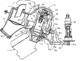
図1は、本発明の実施の形態に係る燃料噴射弁配置構造の要部を示す構成図である。エンジン1は、例えば4気筒エンジン(1気筒のみ図示)であり、各気筒ごとに吸気通路2内にスロットル弁3を備え、このスロットル弁3を備えたスロットルボディ部分の下流側の吸気通路2に臨んで第1燃料噴射弁4が設けられる。吸気通路2の上流側端部にはエアクリーナ5が設けられる。このエアクリーナ5内に、吸気通路2の端部に接続されたファンネル6が設けられる。
FIG. 1 is a configuration diagram showing a main part of a fuel injection valve arrangement structure according to an embodiment of the present invention. The engine 1 is, for example, a four-cylinder engine (only one cylinder is shown), and is provided with a throttle valve 3 in the
エアクリーナ5は、上ケース5aと下ケース5bとからなり、上ケース5aに設けたダクト7から外気を取入れ、エアクリーナエレメント8を通してファンネル6側に供給する。下ケース5bの前側には、特に高出力運転で走行する場合に使用する過給用の空気取入れ口9が設けられる。この空気取入れ口9は、通常時はキャップ10により塞がれている。
The
ファンネル6の拡大した開口端部に第2燃料噴射弁11が設けられる。この第2燃料噴射弁11は、外形が滑らかな曲面形状のカバー12に覆われた状態で、その先端の噴射口部分がファンネル6の開口面より内部側に挿入された位置に配置される。カバー12は燃料噴射弁11の外形に沿ってその周囲側面を覆う形状であり、小径の噴射口部分がファンネル開口面内に挿入され、径が大きい上側部分はファンネル開口面より外側に出ている。より詳しくは、先端側の最も小径部分がファンネルの基本径部分に入り込み、前記小径部分より大径部がファンネルの拡径部に対応するように位置する。このように、燃料噴射弁11の小径の噴射口部分のみをファンネル6内部に挿入することにより、ファンネル開口面を塞ぐ部分を小さくして吸気抵抗の増加を小さく抑えることができる。
A second
カバー12は、これを取付けた支持部材(図示しない)とともに、下ケース5b側から立設したボルトやこれが挿通するカラー等からなる支柱(図示しない)により支持される。このようなカバー12に各気筒の第2燃料噴射弁11が装着され、気筒配列方向(図面に垂直方向)に4個並べて配設される。
The
エアクリーナ5の下側には、第1燃料噴射弁4に燃料を供給するための第1燃料パイプ13が、各気筒の第1燃料噴射弁4の配列方向(図面に垂直方向)に沿って設けられる。同様に、エアクリーナ5内には、第2燃料噴射弁11に燃料を供給するための第2燃料パイプ14が設けられる。
A
第1燃料パイプ13の入口側端部には、図示しない燃料ポンプに接続する燃料供給管15から分岐または連続する往き管15bが接続され、出口側端部に燃料の戻り管16bが接続される。
The
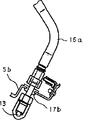
第2燃料パイプ14の入口側端部には、燃料供給管15から分岐または連続する往き管15aが接続され、出口側端部に戻り管16aが接続される。この戻り管16aは、第1燃料パイプ13に接続される。
A
第2燃料パイプ14に接続する往き管15aは、図示しないグロメットを介して下ケース5bの側壁を貫通してエアクリーナ5の内部に配設される。また、第2燃料パイプ14の戻り管16aは、図示しないグロメットを介して下ケース5bの下壁を貫通してエアクリーナ5の外部に配設される。このようなグロメット等のシール部材を介してこれらの往き管15aおよび戻り管16aがエアクリーナ5の下ケース5bを貫通するため、貫通部のシール性は十分に確保される。
The
このような構成の燃料配管経路において、燃料供給管15を通して図示しない燃料ポンプから送られた燃料は、この燃料供給管15から分岐する各往き管15b,15aを介して第1燃料パイプ13および第2燃料パイプ14に供給される。第1燃料パイプ13に供給された余剰燃料は、戻り管16bを通して図示しない燃料タンクに戻る。第2燃料パイプ14に供給された余剰燃料は、戻り管16aを通して第1燃料パイプ13に供給され、その後戻り管16bを通して燃料タンクに戻る。
In the fuel piping path having such a configuration, the fuel sent from the fuel pump (not shown) through the
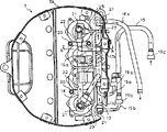
図2から図12までは、本発明のさらに詳細な実施形態を示す。各図中、前記図1の各部分に対応する部分には同じ番号を付してある。図2はエアクリーナの断面図、図3はその平面図、図4は図3のA−A部分の断面図である。 2 to 12 show a more detailed embodiment of the present invention. In each figure, the same number is attached | subjected to the part corresponding to each part of the said FIG. 2 is a cross-sectional view of the air cleaner, FIG. 3 is a plan view thereof, and FIG. 4 is a cross-sectional view of the AA portion of FIG.
燃料ポンプ18(図2)に接続された燃料供給管15は、第1および第2燃料パイプ13,14に燃料を供給する2本の往き管15b,15aに分岐し、それぞれジョイント21(図3)を介して各燃料パイプ13,14に接続される。第2燃料パイプ14に接続される往き管15aは、グロメット17aを介してエアクリーナ5の下ケース5bを貫通する。第1燃料パイプ13には、各気筒に対応して4個の第1燃料噴射弁4が取付けられ、その出口側端部はジョイント21(図3)を介して戻り管16bに接続される。Tは燃料タンクの底面を示す。エアクリーナ等はこの燃料タンク底面Tの下側の狭いスペースに配設されている。
The
第2燃料パイプ14には、各気筒に対応した4個の第2燃料噴射弁11が取付けられ、その出口側端部はジョイント21を介して戻り管16aに接続される。この戻り管16aは、図4に示すように、グロメット17bを介してエアクリーナ5の下ケース5bを貫通し、第1燃料パイプ13に接続される。
Four second
第2燃料噴射弁11は、カバー12内に装着され、第2燃料パイプ14と一体成形された支持部材22(後述の図10,11,12参照)に支持される。この支持部材22は4本のボルト20およびこのボルト20が挿通するカラー28からなる支柱により、ファンネル下部のフランジに対し固定支持される。各燃料噴射弁にはコネクタ29(図3)を介して電気配線23が接続される。4個のファンネルは個々にボルト20’によりスロットルボディ2cに固定支持される。
The second
燃料流路を構成する各配管上には各配管部材を接続するための接続具19a,19b,19cが設けられる。これらの接続具は、配管を押込むことによりスナップ式に接続される構成である。各配管は、その位置を固定保持して、特にエアクリーナへの貫通部分のシール性を確実に保つため、およびポンプから送られる燃料の圧力損失を小さくするために、剛性の大きい金属パイプ(又は剛性の大きい樹脂材料)で構成される。したがって、特に接続具19a,19bについては、相互に位置が近いため、一緒に取付け取外しを行う必要があり、メンテナンスの作業性等も考慮して各接続具19の接続の押込み方向は1方向に揃えておくことが望ましい。
On each pipe constituting the fuel flow path, connecting
図5はエアクリーナ単体の断面図、図6はその平面図である。エアクリーナ5の上ケース5aと下ケース5bは、周縁に沿った合せ面の凹部および凸部を嵌合させて密封的に結合する嵌め合わせ型式の構成であり、ネジ25により相互に固定される。下ケース5bには、吸気通路2(図1、図2)のスロットルボディ上端部を密封的に挿通させるためのシール部材83が装着される。エアクリーナエレメント8は、図6の斜線で示すように、略コ字状に配置され、ネジ24により上ケース5a側に取付けられる。
FIG. 5 is a sectional view of the air cleaner alone, and FIG. 6 is a plan view thereof. The upper case 5a and the
図7は、吸気通路(スロットルボディ)と第1燃料噴射弁の燃料配管経路の平面図であり、図8はその側面図、図9は図7のB−B断面図である。内部に吸気通路2が形成され、スロットル弁3を有するスロットルボディ2cは、その底部に一体形成されたフランジ部2aを有し、このフランジ部2aを介してエンジン側に取付けられる。このフランジ部2aに近接して、スロットル弁3の下流側となる位置に燃料噴射弁の保持枠2bが一体形成され、この保持枠2bに第1燃料噴射弁4の先端の噴射口部分が装着される。26(図9)は燃料噴射弁4の電気配線のコネクタ装着部である。
7 is a plan view of the intake passage (throttle body) and the fuel piping path of the first fuel injection valve, FIG. 8 is a side view thereof, and FIG. 9 is a sectional view taken along line BB in FIG. An
4個のスロットルボディ2cがエンジンの4つの気筒(図示しない)に対応して車幅方向に並列して設けられ、このスロットルボディ2cに沿って第1燃料パイプ13が取付けられる。この第1燃料パイプ13の各スロットルボディ2cの位置に各第1燃料噴射弁4が取付けられる。この第1燃料パイプ13の途中には、前述のように、上側の第2燃料パイプからの戻り管16aが接続される(図8)。
Four
図10は第2燃料パイプ14の平面図、図11はその側面図、図12は図11のC−C部分の断面図である。第2燃料パイプ14は、4本のアーム状の支持部材22とともに一体成形される。支持部材22の先端にはボルト通し孔20aが形成される。第2燃料パイプ14は、この支持部材22の孔20aにボルト20(図2、図3)を通し,カラー28(図2、図3)を介してスロットルボディの上側のファンネル6(図2)の上側に支持される。この燃料パイプ14には、各スロットルボディの位置に対応して所定間隔で前述のカバー12がネジ27により取付けられ、第2燃料噴射弁11が装着される。カバー12は、前述のように、滑らかな外面形状を有し、図12に示すように、電気配線のコネクタ装着部26を露出させて第2燃料噴射弁11を覆う。
10 is a plan view of the
ボルト20およびカラー28は、ファンネル同士の間に設けられる。コネクタ装着部26や燃料配管15a,16a等は第2燃料通路を挟んでフィルターエレメント8の反対側に配置される。これにより、フィルターエレメント8を通過して各ファンネルへ流入する吸気の流れの妨げとならない。
The
1:エンジン
2:吸気通路
3:スロットル弁
4:第1燃料噴射弁
5:エアクリーナ
5a:上ケース
5b:下ケース
6:ファンネル
7:ダクト
8:エアクリーナエレメント
9:空気取入れ口
10:キャップ
11:第2燃料噴射弁
12:カバー
13:第1燃料パイプ
14:第2燃料パイプ
15:燃料供給管
15a,15b:往き管
16a,16b:戻り管
17a,17b:グロメット
18:燃料ポンプ
19:接続具
20:ボルト
21:ジョイント
22:支持部材
23:電気配線
24,25,27:ネジ
26:コネクタ保持部
28:カラー
29:コネクタ
1: Engine 2: Intake passage 3: Throttle valve 4: First fuel injection valve 5: Air cleaner 5a:
Claims (4)
前記ファンネルは、前記吸気ボックス内に設けられ、
前記各第2燃料噴射弁に燃料を供給する燃料パイプと、
前記吸気ボックス内に設けられ且つ前記各第2燃料噴射弁の周囲側面を覆う滑らかな外面形状のカバーとを備え、
前記カバーは、前記各第2燃料噴射弁の外形に沿い、前記各第2燃料噴射弁の噴射口側に向かって先細りの形状に形成され、前記燃料パイプに固定されている、燃料噴射式エンジン。 Corresponding to each cylinder of an engine having a plurality of cylinders, an intake passage, a throttle valve provided in the intake passage, a first fuel injection valve facing the intake passage on the downstream side of the throttle valve, and the intake passage In a fuel injection type engine provided with a funnel provided at the upstream end of the second fuel injection valve and a second fuel injection valve facing the intake passage, and provided with an intake box,
The funnel is provided in the intake box,
A fuel pipe for supplying fuel to each of the second fuel injection valves;
A cover having a smooth outer surface provided in the intake box and covering a peripheral side surface of each of the second fuel injection valves ,
The cover is formed in a tapered shape along the outer shape of each second fuel injection valve toward the injection port side of each second fuel injection valve, and is fixed to the fuel pipe. .
Priority Applications (1)
| Application Number | Priority Date | Filing Date | Title |
|---|---|---|---|
| JP2005012348A JP4030065B2 (en) | 2005-01-20 | 2005-01-20 | Fuel injection engine |
Applications Claiming Priority (1)
| Application Number | Priority Date | Filing Date | Title |
|---|---|---|---|
| JP2005012348A JP4030065B2 (en) | 2005-01-20 | 2005-01-20 | Fuel injection engine |
Related Parent Applications (1)
| Application Number | Title | Priority Date | Filing Date |
|---|---|---|---|
| JP10267762A Division JP2000097131A (en) | 1998-09-22 | 1998-09-22 | Setting structure of fuel injection valve |
Publications (3)
| Publication Number | Publication Date |
|---|---|
| JP2005106068A JP2005106068A (en) | 2005-04-21 |
| JP2005106068A5 JP2005106068A5 (en) | 2005-08-18 |
| JP4030065B2 true JP4030065B2 (en) | 2008-01-09 |
Family
ID=34545451
Family Applications (1)
| Application Number | Title | Priority Date | Filing Date |
|---|---|---|---|
| JP2005012348A Expired - Lifetime JP4030065B2 (en) | 2005-01-20 | 2005-01-20 | Fuel injection engine |
Country Status (1)
| Country | Link |
|---|---|
| JP (1) | JP4030065B2 (en) |
Families Citing this family (1)
| Publication number | Priority date | Publication date | Assignee | Title |
|---|---|---|---|---|
| JP5883742B2 (en) * | 2012-08-10 | 2016-03-15 | 本田技研工業株式会社 | Suction type vehicle intake structure |
-
2005
- 2005-01-20 JP JP2005012348A patent/JP4030065B2/en not_active Expired - Lifetime
Also Published As
| Publication number | Publication date |
|---|---|
| JP2005106068A (en) | 2005-04-21 |
Similar Documents
| Publication | Publication Date | Title |
|---|---|---|
| EP2599989B1 (en) | Air-intake device | |
| JP2000097131A (en) | Setting structure of fuel injection valve | |
| US20060157021A1 (en) | Throttle body for V-type engine | |
| JP3352572B2 (en) | Intake device for multi-cylinder internal combustion engine | |
| JP2019044644A (en) | Intake system | |
| JP3428778B2 (en) | Intake device for internal combustion engine | |
| JP4030065B2 (en) | Fuel injection engine | |
| JP5825903B2 (en) | Resin intake manifold | |
| US9315228B2 (en) | Saddle type vehicle | |
| JP2000097132A (en) | Fuel piping structure | |
| JP2011132816A (en) | Intake manifold | |
| JP2010265870A (en) | Intake manifold | |
| JP4353434B2 (en) | FUEL SUPPLY DEVICE, VEHICLE, AND METHOD FOR ASSEMBLING FUEL SUPPLY DEVICE | |
| US7128056B2 (en) | Throttle body in fuel injection apparatus | |
| CA2841155C (en) | Intake apparatus | |
| EP1801412A2 (en) | Fuel supply pipe structure in two fuel injection valve type throttle body | |
| JP5227702B2 (en) | Intake manifold | |
| JP4771229B2 (en) | Engine intake system | |
| JPH11247727A (en) | Device for introducing blowby gas or the like of internal combustion engine to intake system | |
| JP2000073893A (en) | Mounting device for throttle body in multi-cylinder internal combustion engine | |
| US7665449B2 (en) | V-type engine | |
| KR102429050B1 (en) | Air cleaner assembly and inlet duct including cyclone | |
| US7063060B2 (en) | Air induction system having an intake manifold including a throttle body | |
| US9316138B2 (en) | Saddle type vehicle | |
| JP2006233927A (en) | Intake system structure for engine |
Legal Events
| Date | Code | Title | Description |
|---|---|---|---|
| A621 | Written request for application examination |
Free format text: JAPANESE INTERMEDIATE CODE: A621 Effective date: 20050120 |
|
| A521 | Written amendment |
Free format text: JAPANESE INTERMEDIATE CODE: A523 Effective date: 20050404 |
|
| A131 | Notification of reasons for refusal |
Free format text: JAPANESE INTERMEDIATE CODE: A131 Effective date: 20070719 |
|
| A521 | Written amendment |
Free format text: JAPANESE INTERMEDIATE CODE: A523 Effective date: 20070918 |
|
| TRDD | Decision of grant or rejection written | ||
| A01 | Written decision to grant a patent or to grant a registration (utility model) |
Free format text: JAPANESE INTERMEDIATE CODE: A01 Effective date: 20071012 |
|
| A61 | First payment of annual fees (during grant procedure) |
Free format text: JAPANESE INTERMEDIATE CODE: A61 Effective date: 20071012 |
|
| R150 | Certificate of patent or registration of utility model |
Free format text: JAPANESE INTERMEDIATE CODE: R150 |
|
| FPAY | Renewal fee payment (event date is renewal date of database) |
Free format text: PAYMENT UNTIL: 20101026 Year of fee payment: 3 |
|
| FPAY | Renewal fee payment (event date is renewal date of database) |
Free format text: PAYMENT UNTIL: 20101026 Year of fee payment: 3 |
|
| FPAY | Renewal fee payment (event date is renewal date of database) |
Free format text: PAYMENT UNTIL: 20111026 Year of fee payment: 4 |
|
| FPAY | Renewal fee payment (event date is renewal date of database) |
Free format text: PAYMENT UNTIL: 20111026 Year of fee payment: 4 |
|
| FPAY | Renewal fee payment (event date is renewal date of database) |
Free format text: PAYMENT UNTIL: 20121026 Year of fee payment: 5 |
|
| FPAY | Renewal fee payment (event date is renewal date of database) |
Free format text: PAYMENT UNTIL: 20121026 Year of fee payment: 5 |
|
| FPAY | Renewal fee payment (event date is renewal date of database) |
Free format text: PAYMENT UNTIL: 20131026 Year of fee payment: 6 |
|
| R250 | Receipt of annual fees |
Free format text: JAPANESE INTERMEDIATE CODE: R250 |
|
| R250 | Receipt of annual fees |
Free format text: JAPANESE INTERMEDIATE CODE: R250 |
|
| R250 | Receipt of annual fees |
Free format text: JAPANESE INTERMEDIATE CODE: R250 |
|
| R250 | Receipt of annual fees |
Free format text: JAPANESE INTERMEDIATE CODE: R250 |
|
| EXPY | Cancellation because of completion of term |