JP4027122B2 - Imaging apparatus and control method thereof - Google Patents
Imaging apparatus and control method thereof Download PDFInfo
- Publication number
- JP4027122B2 JP4027122B2 JP2002057222A JP2002057222A JP4027122B2 JP 4027122 B2 JP4027122 B2 JP 4027122B2 JP 2002057222 A JP2002057222 A JP 2002057222A JP 2002057222 A JP2002057222 A JP 2002057222A JP 4027122 B2 JP4027122 B2 JP 4027122B2
- Authority
- JP
- Japan
- Prior art keywords
- imaging
- display
- image
- moving image
- recording
- Prior art date
- Legal status (The legal status is an assumption and is not a legal conclusion. Google has not performed a legal analysis and makes no representation as to the accuracy of the status listed.)
- Expired - Fee Related
Links
Images


Description
【0001】
【発明の属する技術分野】
本発明は、静止画と動画が撮影できる撮像装置に関し、特にファインダ画の表示に関するものである。
【0002】
【従来の技術】
近年、パーソナルコンピュータの高性能化,低価格化が飛躍的に進み、民生レベルで高精細な静止画像あるいは動画像を、手軽にしかも多量に取り扱える環境が普及し始めている。一方、撮像機器の進展も目覚しく、入力デバイスの多画素化、記録メディアの高容量化により、高精細の静止画像撮影と同時に、動画像も記録可能な製品が実現されている。
【0003】
従来、この種の製品として、デジタルスチルカメラとデジタルビデオカメラを融合した製品形態が提案されている。たとえば、100万画素以上の多画素CCDを搭載し、高精細静止画を固体メモリに撮像記録し、一方、この高精細画像から一部の動画像データを切り出して、SD規格(HDデジタルVCR協議会準拠)あるいはMPEG2規格に則した標準動画(720×480画素/フレーム)の撮影をするものである。
【0004】
また、多画素CCDを搭載して高精細静止画の撮像を実現しながら、動画撮影にはフレームレートを落として簡易動画として固体メモリに動画像を記録再生する製品も提案されている。
【0005】
【発明が解決しようとする課題】
CCDの画素数増加によって、静止画像の高精細化が達成される。しかしながら、動画像に関しては多画素CCD総ての画素情報を、1/60(秒)ごとに読み出そうとしても、高速サンプリング処理、電荷移動時間の遅れなど、CCDデバイス自体の動作限界を越え、処理が破綻してしまう。
【0006】
そこで、多画素CCDから動画像の読み出しを行う場合、総ての画素情報を読み出さずに、読み出し可能な範囲だけを選択的に抽出している。たとえば、100万画素以上の多画素CCDを用いた場合、この領域の中央部、すなわち上下左右の一部の周辺領域を読み出さず、中央部の1280×960画素だけ読み出して、これを動画情報とするものである。
【0007】
更なるCCDデバイスの多画素化が進展すれば、静止画像と動画像の画角差はますます大きくなる。被写体を前に、動画を撮りながら静止画を撮影したり、静止画を撮りながら動画の撮影を開始しようとすると、両者の構図を大幅に修整する手間が避けられず、動画,静止画双方のスムーズな撮影が損なわれてしまうという課題がある。
【0008】
本発明は、このような状況のもとでなされたもので、静止画撮影と動画撮影を切り替えた際の違和感が少なく、撮影条件に合わせた静止画と動画の最適な使い分けが容易にできる撮像装置,撮像方法を提供することを目的とするものである。
【0009】
【課題を解決するための手段】
前記目的を達成するため、本発明の撮像装置は、静止画および動画が撮像できる撮像手段と、前記撮像手段から出力される画像信号を表示する表示手段と、前記表示手段を制御する制御手段を有する撮像装置であって、前記制御手段は、前記撮像装置が撮像スタンバイ状態となったときに、静止画の撮像エリアを全画面表示したうえで、動画の撮像エリアを示す枠を重畳表示するように前記表示手段を制御し、前記撮像スタンバイ状態から静止画記録が指示されると重畳表示した前記枠を消去するように前記表示手段を制御するとともに、前記撮像スタンバイ状態から動画記録が指示されると動画の撮像エリアを全画面表示するように前記表示手段を制御することを特徴とする。
本発明の撮像装置の制御方法は、静止画および動画が撮像できる撮像手段と、前記撮像手段から出力される画像信号を表示する表示手段と、前記表示手段を制御する表示制御手段を有する撮像装置の制御方法において、前記撮像装置が撮像スタンバイ状態となったときに、静止画の撮像エリアを全画面表示するとともに、動画の撮像エリアを示す枠を重畳表示するように前記表示手段を制御する第1のステップと、前記撮像スタンバイ状態から静止画記録が指示されると重畳表示した前記枠を消去し、前記撮像スタンバイ状態から動画記録が指示されると動画の撮像エリアを全画面表示するように前記表示手段を制御する第2のステップとを有することを特徴とする。
【0018】
【発明の実施の形態】
以下本発明の実施の形態を撮像記録再生装置の実施例により詳しく説明する。なお、本発明は、装置の形に限らず、実施例の説明に裏付けられた、方法の形で実施することもできる。
【0019】
【実施例】
(実施例1)
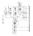
図1は、実施例1である“撮像記録再生装置”の機能ブロック図である。同図の構成要素を説明する。101はレンズユニット、102は撮像処理、103はカメラ信号処理、104は標準映像変換、105はスイッチ、106はメモリ、107はメモリ制御、108はフィルタ、109はフィルタ制御、110はCPU、111は動画記録再生処理、112は動画記録メディア、113は静止画記録再生処理、114は静止画記録メディア、115は表示信号処理、116は表示画面、117はライン入出力処理、118はライン入出力端子、119はデータバスである。
【0020】
図1の構成による動作を説明する。不図示の被写体に対し、レンズユニット101を介して一連のフオーカス制御,ズーム制御,絞り制御等が行われる。撮像処理102は、固体撮像素子(以下、CCDと記す)を備え、レンズユニット101によって撮像面に結像、かつ光量を調節された画像を光電変換して映像信号を出力する。ここでは、装備されるCCDを高精細静止画撮影に対応した有効画素1280×960画素の多画素タイプCCDとする。カメラ信号処理103は、映像信号をデジタル化して、ゲイン調整,ガンマ補正,ホワイトバランス調整等、所定のカメラ信号処理を行う。
【0021】
標準映像変換104は、高精細映像(1280×960)を標準映像信号(720×480)にダウンコンバートする処理を行うもので、スイッチ105のA側で標準映像信号記録を、B側で高精細映像信号記録を選択する。
【0022】
標準動画像を撮像記録する場合には、A側に接続して、高精細画像を標準画像にダウンコンバートして出力する。一方、高精細静止画像を撮像記録する場合には、B側に接続する。
【0023】
次段のメモリ106は、高精細画像データを複数フレーム記憶可能なメモリで、107はこのメモリのアドレス制御を行うメモリ制御である。CPU110はシステム全体の制御中枢を担うものである。
【0024】
高精細静止画像を記録する動作を説明する。この場合、スイッチ105はB側に接続され、有効画素1280×960のデータが一旦メモリ106に書き込まれる。続いてメモリ106から読み出された1280×960の画像データはフィルタ108に入力されるがデータを加工せず、そのまま出力する。静止画記録再生113は、記録時、入力されたデジタル画像データをJPEG方式等でデータ圧縮し、フラッシュメモリ等の静止画記録媒体114に記録する。
【0025】
標準動画像を記録する動作を説明する。この場合、スイッチ105はA側に接続され、標準画像変換104は、入力された高精細画像データを水平垂直方向それぞれにダウンサンプリングし、標準画像変換出力である有効画素720×480の画像データを出力してメモリ106に書き込む。次に、メモリ106から読み出された信号は、動画記録再生処理111にて、動画データ圧縮処理を行い、ディスクまたは磁気テープ等の記録媒体112に記録する。
【0026】
次に、高精細静止画または動画を撮像する際の表示について説明する。
【0027】
表示信号処理115は、メモリ106から読み出されるデジタル画像データをD/A変換して液晶表示画面116をドライブし、映像表示を行う。ライン入出力処理117は、ライン入力時は端子118から入力されたアナログ映像信号をA/D変換してデジタル画像データをメモリ106に書き込み、またライン出力時には、メモリ106から読み出されたデジタル画像データをD/A変換し、端子118にアナ口グ出力するものである。
【0028】
図2に、液晶表示画面116の例を示す。この例は、静止画撮像トリガ,動画撮像トリガを押す前に撮像する範囲を確認するための画、いわゆる“ファインダ画”の例である。ここでは、表示画面内にワクを設けて、高精細静止画の撮像エリア(画角ということもできる)と標準動画の撮像エリアを同時識別する構成となっている。このワクのサイズは、高精細静止画から標準動画像を所定のフレームレートで抽出し、記録可能なフレームサイズに設定してある。
【0029】
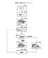
本実施例による、動画と高精細静止画を撮像記録する動作を図3のフローチャートで概略的に説明する。図3において、ステップ301(図でS301と略記する、以下同様)で装置が起動する。その後、ステップ302で、撮像記録または媒体再生のモード選択で撮像モードが選ばれると、ステップ303へ移り、表示画面(ファインダ画)に動画と静止画の撮像エリアを識別するワクを表示し、ステップ304へ移る。ステップ304では、撮像スタンバイ状態となり、ここでは動画または高精細静止画のどちらでもトリガ(記録開始スイッチ)をかけることができる。トリガがかかるとステップ305へ移り、動画トリガが押されていればステップ306へ移り、実際に撮像記録できる動画のフレームサイズを、正規のフレームレートで画面表示するとともに、動画を撮像記録する。一方、高精細静止画トリガが押されていると、ステップ307へ移り、表示画面にある、動画と静止画の撮像エリアを識別するワクを消去し、表示エリアいっぱいの静止画像を撮像記録し、表示画面に表示する。ステップ306における所定枚数の動画の撮像記録、またステップ307における高精細静止画の撮像記録が終了すると、ステップ308に移り撮像記録が一時停止となり、ステップ304へ戻って撮像スタンバイ状態となり、表示画面に動画と静止画の撮像エリアを識別するワクを再び表示する。以降、ステップ304ないしステップ308の動作を繰り返す。
【0030】
本実施例では、フラッシュメモリ等の静止画記録媒体にある高精細静止画像とディスクまたは磁気テープ上にある動画像データを相互変換することも可能である。
【0031】
静止画データを動画記録媒体に記録する動作を図1により説明する。フラッシュメモリ等の静止画記録媒体114から出力されるJPEG等の圧縮データを静止画記録再生処理113にて復号処理し1280×960の画素データを出力し、フィルタ108にてダウンコンパートする。フィルタ108では、動画記録媒体への記録レートに従って、水平垂直方向に1/2ダウンサンプリングして、720×480の画素データを得て、これをメモリ106に書き込む。以後、所定の動画記録動作を行う。
【0032】
一方、動画データを静止画記録媒体に記録する動作を説明する。ディスクまたは磁気テープ等の動画記録媒体112上にある動画データを動画記録再生処理111にて復号処理し、メモリ106に書き込む。続いて、フィルタ108にて所望の画素サイズに変換した後、静止画記録再生処理113にてJPEG等の圧縮を行いフラッシュメモリ等の記録媒体114に記録する。
【0033】
以上説明したように、本実施例によれば、撮影者が静止画と動画それぞれ記録可能なエリア(構図)差を常時モニタリングしながら撮影できるので、高精細静止画を撮った後、標準動画撮影に切り替えた時のエリア(構図)縮小の違和感を軽減できる。−方、動画撮影を行った後、高精細静止画撮影に切り替えた時に生じるエリア(構図)拡大の違和感を軽減できる。
【0034】
このことは、動画と静止画に生じる画角差を常に認識しながらの相乗効果として、撮影条件に合わせた動画と静止画の最適な使い分けを提供することができる。
【0035】
(実施例2)
図4は、実施例2である“撮像記録再生装置”の表示画面例である。本実施例では、表示画面に、標準動画の撮像エリアとそれ以外のエリアに輝度差を設けて、高精細静止画と標準動画のエリアを同時識別する構成となっている。輝度差設定エリアのサイズは、高精細静止画から標準動画像を所定のフレームレートで抽出し、記録可能なフレームサイズに設定してあり、動画記録領域は何ら加工しない通常輝度レベルとし、それ以外の領域については輝度レベルを1/2に下げて表示する。
【0036】
本実施例のハードウエア構成は、図1と同様なので、図1とその説明を援用し、ここでの説明を省略する。
【0037】
本実施例における、動画と高精細静止画の撮像記録の概略的動作を図5のフローチャートで説明する。図5において、ステップ501で装置が起動する。その後、ステップ502で、撮像記録または媒体再生のモード選択で撮像モードが選ばれるとステップ503に移り、表示画面(ファインダ画)に動画と静止画の撮像エリアを識別する輝度差を設ける。すなわち、動画記録領域は通常輝度レベル、それ以外の高精細静止画部分の領域は動画領域に対して1/2に下げて表示する。続いてステップ504へ移り撮像スタンバイ状態となる。ここでは、動画または高精細静止画のどちらでもトリガ(記録開始スイッチ)をかけることができる。トリガがかかるとステップ505へ移り、動画トリガが押されていればステップ506へ移り、実際に撮像記録できる動画のフレームサイズを、正規のフレームレートで画面表示し、動画を撮像記録する。一方、高精細静止画トリガが押されていればステップ507へ移り、ステップ504で設けた輝度差を解消し、表示エリアいっぱいの静止画像を撮像記録し、表示画面に表示する。ステップ506における所定枚数の動画の撮像記録、またステップ507における高精細静止画の撮像記録が終了すると、ステップ508に移り撮像記録が一時停止となり、ステップ504へ戻って撮像スタンバイ状態となり、表示画面に動画と静止画の撮像エリアを識別する輝度差を再び設ける。以降、ステップ504ないしステップ508の動作を繰り返す。
【0038】
以上の説明から明らかなように、本実施例においても、実施例1と同様の効果を得ることができる。
【0039】
(実施例3)
図6は、実施例3である“撮像記録再生装置”の動作を示すフローチャートである。本実施例では、標準動画の撮像記録領域はカラー表示し、それ以外の領域は白黒表示にして、動画と静止画のエリアを同時識別する構成となっている。カラー部分設定エリアのサイズは、高精細静止画内から標準動画像を所定のフレームレートで抽出し、記録可能なフレームサイズに設定してある。
【0040】
本実施例のハードウエア構成は、図1と同様なので、図1とその説明を援用し、ここでの説明を省略する。
【0041】
本実施例により動画と高精細静止画を撮像記録する動作を図6のフローチャートで説明する。ステップ601で装置が起動し、その後、ステップ602で撮像記録または媒体再生のモード選択で撮像モードを選ばれると、ステップ603へ移動し、表示画面(ファインダ画)に動画と静止画の撮像エリアを識別するカラー信号有無の設定差を設ける。すなわち、動画記録領域はカラー表示、それ以外の高精細静止画部分の領域は白黒表示する。ステップ604で撮像スタンバイ状態となり、動画または高精細静止画のどちらでもトリガ(記録開始スイッチ)をかけることができる。
【0042】
ここでトリガがかかると、ステップ605へ移り、動画トリガが押されているとステップ606へ移り、実際に撮像記録できる動画のフレームサイズを、正規のフレームレートで画面表示するとともに、動画を撮像記録する。一方、高精細静止画トリガを押されていると、ステップ407へ移り、ステップ603で設定したカラー表示の有無を解消し、表示エリアいっぱいのカラー静止画像を撮像記録するとともに画面表示する。ステップ606における所定枚数の動画の撮像記録、またステップ607における高精細静止画の撮像記録が終了すると、ステップ608に移り撮像記録が一時停止となり、ステップ604へ戻って撮像スタンバイ状態となり、表示画面に動画と静止画の撮像エリアを識別するカラー表示の有無を再び表示する。以降、ステップ604ないしステップ608の動作を繰り返す。
【0043】
以上の説明から明らかなように、本実施例においても、実施例1と同様の効果を得ることができる。
【0044】
【発明の効果】
以上説明したように、本発明によれば、撮像スタンバイ状態では、撮影者が静止画と動画それぞれ撮像可能なエリア(構図)差を常時モニタリングすることができるとともに、撮像スタンバイ状態から静止画撮影を行う場合にも、撮像スタンバイ状態から動画撮影を行う場合にも違和感のない自然な表示を行うことができる。
【0045】
このことは、動画と静止画に生じる画角差を常に認識しながらの相乗効果として、撮影条件に合わせた動画と静止画の最適な使い分けを提供することができる。
【図面の簡単な説明】
【図1】 実施例1の機能ブロック図
【図2】 表示画面例を示す図
【図3】 実施例1の動作を示すフローチャート
【図4】 実施例2における表示画面例を示す図
【図5】 実施例2の動作を示すフローチャート
【図6】 実施例3の動作を示すフローチャート
【符号の説明】
102 撮像処理
110 CPU
116 表示画面[0001]
BACKGROUND OF THE INVENTION
The present invention relates to an imaging apparatus that can capture still images and moving images, and more particularly to display of a finder image.
[0002]
[Prior art]
In recent years, the performance and cost of personal computers have been dramatically improved, and an environment in which high-definition still images or moving images can be handled easily and in large quantities at the consumer level has begun to spread. On the other hand, the development of imaging devices has been remarkable, and products capable of recording moving images simultaneously with high-definition still image shooting have been realized by increasing the number of pixels of input devices and increasing the capacity of recording media.
[0003]
Conventionally, as this type of product, a product form in which a digital still camera and a digital video camera are integrated has been proposed. For example, a multi-pixel CCD with 1 million pixels or more is mounted, and high-definition still images are captured and recorded in a solid-state memory. On the other hand, a part of moving image data is cut out from this high-definition image and SD standard (HD digital VCR consultation) Society standard) or a standard moving image (720 × 480 pixels / frame) conforming to the MPEG2 standard.
[0004]
In addition, a product has been proposed in which a multi-pixel CCD is mounted to capture a high-definition still image, and a moving image is recorded and reproduced in a solid-state memory as a simple moving image by reducing the frame rate for moving image shooting.
[0005]
[Problems to be solved by the invention]
High definition of a still image is achieved by increasing the number of pixels of the CCD. However, regarding moving images, even if trying to read out pixel information of all multi-pixel CCDs every 1/60 (seconds), the operating limit of the CCD device itself such as high-speed sampling processing, delay of charge transfer time, etc. Processing breaks down.
[0006]
Therefore, when a moving image is read from a multi-pixel CCD, only a readable range is selectively extracted without reading all pixel information. For example, when using a multi-pixel CCD of one million strokes element, the central portion of this region, i.e. without reading a portion of the peripheral region of the vertical and horizontal, reads only 1280 × 960 pixels in the central portion, moving picture information it It is what.
[0007]
As the number of pixels of a CCD device further increases, the difference in the angle of view between a still image and a moving image will increase. If you try to shoot a still image while shooting a movie in front of the subject, or start shooting a movie while shooting a still image, it will be unavoidable to rework the composition of both. There is a problem that smooth shooting is impaired.
[0008]
The present invention has been made under such circumstances, and there is little discomfort when switching between still image shooting and movie shooting, and imaging that can easily use optimal still images and movies according to shooting conditions is easy. The object is to provide an apparatus and an imaging method.
[0009]
[Means for Solving the Problems]
To achieve the above object, an imaging apparatus of the present invention includes an imaging means for still and moving images can be captured, and display means for displaying an image signal output from said image pickup means, control means for controlling the pre-Symbol display means When the imaging apparatus is in an imaging standby state , the control unit displays a still image imaging area on a full screen and then superimposes a frame indicating a moving image imaging area. The display unit is controlled so that when the still image recording is instructed from the imaging standby state, the display unit is controlled to erase the frame that is superimposed and the moving image recording is instructed from the imaging standby state. Then, the display means is controlled to display the moving image imaging area in full screen.
An image pickup apparatus control method according to the present invention includes an image pickup unit that can pick up a still image and a moving image, a display unit that displays an image signal output from the image pickup unit, and a display control unit that controls the display unit. In this control method, when the imaging device is in an imaging standby state, the display unit is controlled so that a still image imaging area is displayed on a full screen and a frame indicating a moving image imaging area is displayed in a superimposed manner. 1 and when the still image recording is instructed from the imaging standby state , the superimposed frame is deleted, and when the moving image recording is instructed from the imaging standby state , the imaging area of the moving image is displayed in full screen. And a second step of controlling the display means.
[0018]
DETAILED DESCRIPTION OF THE INVENTION
Hereinafter, embodiments of the present invention will be described in detail with reference to an example of an imaging recording / reproducing apparatus. Note that the present invention is not limited to the form of the apparatus, and can be implemented in the form of a method supported by the description of the embodiments.
[0019]
【Example】
Example 1
FIG. 1 is a functional block diagram of an “imaging recording / reproducing apparatus” according to the first embodiment. The components shown in FIG. 101 is a lens unit, 102 is imaging processing, 103 is camera signal processing, 104 is standard video conversion, 105 is a switch, 106 is memory, 107 is memory control, 108 is filter, 109 is filter control, 110 is CPU, 111 is Movie recording / playback processing, 112 is movie recording media, 113 is still image recording / playback processing, 114 is still image recording media, 115 is display signal processing, 116 is a display screen, 117 is line input / output processing, 118 is line input / output
[0020]
The operation according to the configuration of FIG. 1 will be described. A series of focus control, zoom control, aperture control, and the like are performed on a subject (not shown) via the
[0021]
The
[0022]
When a standard moving image is captured and recorded, the high-definition image is down-converted to a standard image by connecting to the A side and output. On the other hand, when a high-definition still image is captured and recorded, it is connected to the B side.
[0023]
The next-
[0024]
An operation for recording a high-definition still image will be described. In this case, the
[0025]
An operation for recording a standard moving image will be described. In this case, the
[0026]
Next, display when capturing a high-definition still image or moving image will be described.
[0027]
The
[0028]
FIG. 2 shows an example of the liquid
[0029]
An operation of capturing and recording a moving image and a high-definition still image according to the present embodiment will be schematically described with reference to a flowchart of FIG. In FIG. 3, the apparatus is activated in step 301 (abbreviated as S301 in the figure, the same applies hereinafter). Thereafter, in step 302, when the imaging mode is selected in the mode of recording / recording or medium reproduction, the process proceeds to step 303, where a display for identifying the imaging area of the moving image and the still image is displayed on the display screen (finder image). Move to 304. In step 304, an imaging standby state is set, and here a trigger (recording start switch) can be applied to either a moving image or a high-definition still image. If a trigger is applied, the process moves to step 305, and if the moving image trigger is pressed, the process moves to step 306, and the frame size of the moving image that can be actually imaged and recorded is displayed on the screen at a regular frame rate, and the moving image is imaged and recorded. On the other hand, if the high-definition still image trigger is pressed, the process proceeds to step 307, where the display identifying the moving image and still image capturing area on the display screen is erased, and the still image of the entire display area is captured and recorded. Display on the display screen. When the recording and recording of a predetermined number of moving images in step 306 and the recording and recording of a high-definition still image in step 307 are completed, the process proceeds to step 308, where the imaging recording is temporarily stopped, and the process returns to step 304 to enter the imaging standby state, and the display screen is displayed. The work for identifying the imaging area of the moving image and the still image is displayed again. Thereafter, the operations from step 304 to step 308 are repeated.
[0030]
In this embodiment, it is possible to mutually convert a high-definition still image on a still image recording medium such as a flash memory and moving image data on a disk or magnetic tape.
[0031]
The operation of recording still image data on a moving image recording medium will be described with reference to FIG. The compressed data such as JPEG output from the still
[0032]
On the other hand, an operation for recording moving image data on a still image recording medium will be described. The moving image data on the moving
[0033]
As described above, according to the present embodiment, the photographer can shoot while constantly monitoring the difference in the area (composition) that can be recorded for each still image and movie. The discomfort of reducing the area (composition) when switching to can be reduced. -On the other hand, the discomfort of the area (composition) expansion that occurs when switching to high-definition still image shooting after moving image shooting can be reduced.
[0034]
As a synergistic effect while always recognizing the angle of view difference between the moving image and the still image, it is possible to provide the optimal use of the moving image and the still image according to the shooting conditions.
[0035]
(Example 2)
FIG. 4 is a display screen example of the “imaging recording / reproducing apparatus” according to the second embodiment. In this embodiment, a luminance difference is provided between the standard moving image capturing area and the other areas on the display screen, so that a high-definition still image and a standard moving image area can be simultaneously identified. The size of the brightness difference setting area is set to a recordable frame size when standard moving images are extracted from high-definition still images at a predetermined frame rate, and the movie recording area is set to a normal brightness level that does not process anything else. The brightness level is reduced to ½ for the display area.
[0036]
Since the hardware configuration of this embodiment is the same as that of FIG. 1, FIG. 1 and the description thereof are used, and the description thereof is omitted here.
[0037]
The schematic operation of moving image and high-definition still image capturing / recording in the present embodiment will be described with reference to the flowchart of FIG. In FIG. 5, the apparatus is activated in step 501. Thereafter, in step 502, when the imaging mode is selected in the imaging recording or medium playback mode selection, the process proceeds to step 503, and a luminance difference for identifying the imaging area of the moving image and the still image is provided on the display screen (finder image). In other words, the moving image recording area is displayed with a normal luminance level, and the other high-definition still image area is reduced to 1/2 with respect to the moving image area. Subsequently, the process proceeds to step 504 to enter an imaging standby state. Here, a trigger (recording start switch) can be applied to either a moving image or a high-definition still image. If a trigger is applied, the process moves to step 505. If the moving image trigger is pressed, the process moves to step 506, and the frame size of the moving image that can be actually imaged and recorded is displayed on the screen at a regular frame rate, and the moving image is imaged and recorded. On the other hand, if the high-definition still image trigger has been pressed, the process proceeds to step 507, where the luminance difference provided in step 504 is eliminated, a still image of the entire display area is captured and recorded, and displayed on the display screen. When the recording and recording of a predetermined number of moving images in step 506 and the recording and recording of a high-definition still image in step 507 are completed, the process proceeds to step 508, where the imaging recording is paused, and the process returns to step 504 to enter the imaging standby state. A luminance difference for recognizing the imaging area of the moving image and the still image is provided again. Thereafter, the operations from step 504 to step 508 are repeated.
[0038]
As is apparent from the above description, the same effects as in the first embodiment can be obtained in this embodiment.
[0039]
Example 3
FIG. 6 is a flowchart illustrating the operation of the “imaging recording / reproducing apparatus” according to the third embodiment. In this embodiment, the standard moving image capturing / recording area is displayed in color, and the other areas are displayed in black and white so that the moving image and still image areas can be identified simultaneously. The size of the color part setting area is set to a recordable frame size by extracting a standard moving image from a high-definition still image at a predetermined frame rate.
[0040]
Since the hardware configuration of this embodiment is the same as that of FIG. 1, FIG. 1 and the description thereof are used, and the description thereof is omitted here.
[0041]
The operation of capturing and recording a moving image and a high-definition still image according to this embodiment will be described with reference to the flowchart of FIG. In step 601, the apparatus is activated, and then, in step 602, when an imaging mode is selected by selecting a mode for recording / recording or reproducing media, the process moves to step 603, where moving image and still image imaging areas are displayed on the display screen (finder image). A setting difference of presence / absence of a color signal to be identified is provided. That is, the moving image recording area is displayed in color, and the other high-definition still image area is displayed in black and white. In step 604, an imaging standby state is set, and a trigger (recording start switch) can be applied to either a moving image or a high-definition still image.
[0042]
If a trigger is applied, the process moves to step 605. If the moving picture trigger is pressed, the process moves to step 606. The frame size of a moving image that can be actually captured and recorded is displayed on the screen at a normal frame rate, and the moving image is captured and recorded. To do. On the other hand, if the high-definition still image trigger is pressed, the process proceeds to step 407, where the presence / absence of color display set in step 603 is canceled, and a color still image of the entire display area is captured and recorded and displayed on the screen. When the recording and recording of a predetermined number of moving images in step 606 and the recording and recording of a high-definition still image in step 607 are completed, the process proceeds to step 608 where the imaging recording is paused, and the process returns to step 604 to enter the imaging standby state, and the display screen is displayed. The presence / absence of color display for identifying the imaging area for moving images and still images is displayed again. Thereafter, the operations from step 604 to step 608 are repeated.
[0043]
As is apparent from the above description, the same effects as in the first embodiment can be obtained in this embodiment.
[0044]
【The invention's effect】
As described above, according to the present invention, in the imaging standby state, the photographer can constantly monitor the difference in the area (composition) in which each of the still image and the moving image can be captured, and the still image shooting can be performed from the imaging standby state. Even when performing moving image shooting from the imaging standby state, a natural display without a sense of incongruity can be performed.
[0045]
As a synergistic effect while always recognizing the angle of view difference between the moving image and the still image, it is possible to provide the optimal use of the moving image and the still image according to the shooting conditions.
[Brief description of the drawings]
1 is a functional block diagram of a first embodiment. FIG. 2 is a diagram showing an example of a display screen. FIG. 3 is a flowchart showing an operation of the first embodiment. FIG. 4 is a diagram showing an example of a display screen in the second embodiment. Flowchart showing the operation of the second embodiment [FIG. 6] Flowchart showing the operation of the third embodiment [Explanation of symbols]
102
116 Display screen
Claims (6)
前記撮像手段から出力される画像信号を表示する表示手段と、
前記表示手段を制御する制御手段を有する撮像装置であって、
前記制御手段は、前記撮像装置が撮像スタンバイ状態となったときに、静止画の撮像エリアを全画面表示したうえで、動画の撮像エリアを示す枠を重畳表示するように前記表示手段を制御し、前記撮像スタンバイ状態から静止画記録が指示されると重畳表示した前記枠を消去するように前記表示手段を制御するとともに、前記撮像スタンバイ状態から動画記録が指示されると動画の撮像エリアを全画面表示するように前記表示手段を制御することを特徴とする撮像装置。Imaging means capable of capturing still images and moving images;
Display means for displaying an image signal output from the imaging means;
An imaging apparatus having a control means for controlling the pre-Symbol display means,
The control unit controls the display unit to display a still image imaging area in a full screen and to superimpose a frame indicating a moving image imaging area when the imaging apparatus is in an imaging standby state. When the still image recording is instructed from the imaging standby state, the display means is controlled so as to delete the superimposed frame, and when the recording of the moving image is instructed from the imaging standby state , the entire imaging area of the moving image is controlled. An imaging apparatus, wherein the display means is controlled to display a screen.
前記撮像手段から出力される画像信号を表示する表示手段と、前記表示手段を制御する制御手段を有する撮像装置であって、
前記制御手段は、前記撮像装置が撮像スタンバイ状態となったときに、静止画の撮像エリアを全画面表示したうえで、動画の撮像エリアとそれ以外のエリアとで表示形態の変化を設けて表示するように前記表示手段を制御し、前記撮像スタンバイ状態から静止画記録が指示されると前記表示形態の変化を解消するように前記表示手段を制御するとともに、前記撮像スタンバイ状態から動画記録が指示されると動画の撮像エリアを全画面表示するように前記表示手段を制御することを特徴とする撮像装置。Imaging means capable of capturing still images and moving images;
An imaging apparatus having display means for displaying an image signal output from the imaging means, and control means for controlling the display means,
When the imaging device is in an imaging standby state , the control means displays a still image imaging area in a full screen, and displays a change in display mode between the moving image imaging area and the other areas. The display unit is controlled so that when the still image recording is instructed from the imaging standby state , the display unit is controlled to cancel the change in the display form, and the moving image recording is instructed from the imaging standby state. Then, the display device is controlled so that the moving image imaging area is displayed on a full screen.
前記撮像装置が撮像スタンバイ状態となったときに、静止画の撮像エリアを全画面表示するとともに、動画の撮像エリアを示す枠を重畳表示するように前記表示手段を制御する第1のステップと、
前記撮像スタンバイ状態から静止画記録が指示されると重畳表示した前記枠を消去し、前記撮像スタンバイ状態から動画記録が指示されると動画の撮像エリアを全画面表示するように前記表示手段を制御する第2のステップとを有することを特徴とする撮像装置の制御方法。In a control method of an image pickup apparatus having an image pickup means capable of picking up a still image and a moving image, a display means for displaying an image signal output from the image pickup means, and a display control means for controlling the display means,
A first step of controlling the display means to display a still image imaging area in a full screen and to superimpose a frame indicating a moving image imaging area when the imaging device is in an imaging standby state ;
The display unit is controlled to erase the frame that is superimposed when a still image recording is instructed from the imaging standby state, and to display a moving image imaging area in full screen when a moving image recording is instructed from the imaging standby state. And a second step of controlling the imaging apparatus.
前記撮像装置が撮像スタンバイ状態となったときに、静止画の撮像エリアを全画面表示するとともに、動画の撮像エリアとそれ以外のエリアとで表示形態の変化を設けて表示するように前記表示手段を制御する第1のステップと、
前記撮像スタンバイ状態から静止画記録が指示されると前記表示形態の変化を解消し、前記撮像スタンバイ状態から動画記録が指示されると動画の撮像エリアを全画面表示するように前記表示手段を制御する第2のステップとを有することを特徴とする撮像装置の制御方法。In a control method of an image pickup apparatus having an image pickup means capable of picking up a still image and a moving image, a display means for displaying an image signal output from the image pickup means, and a display control means for controlling the display means,
When the image pickup apparatus is in an image pickup standby state, the display unit displays the still image pickup area in full screen and displays the change in display form between the moving image pickup area and the other areas. A first step of controlling
Control of the display means to cancel the change in the display mode when the still image recording is instructed from the imaging standby state, and to display the imaging area of the moving image in full screen when the moving image recording is instructed from the imaging standby state. And a second step of controlling the imaging apparatus.
Priority Applications (1)
| Application Number | Priority Date | Filing Date | Title |
|---|---|---|---|
| JP2002057222A JP4027122B2 (en) | 2002-03-04 | 2002-03-04 | Imaging apparatus and control method thereof |
Applications Claiming Priority (1)
| Application Number | Priority Date | Filing Date | Title |
|---|---|---|---|
| JP2002057222A JP4027122B2 (en) | 2002-03-04 | 2002-03-04 | Imaging apparatus and control method thereof |
Publications (3)
| Publication Number | Publication Date |
|---|---|
| JP2003259161A JP2003259161A (en) | 2003-09-12 |
| JP2003259161A5 JP2003259161A5 (en) | 2005-08-25 |
| JP4027122B2 true JP4027122B2 (en) | 2007-12-26 |
Family
ID=28667546
Family Applications (1)
| Application Number | Title | Priority Date | Filing Date |
|---|---|---|---|
| JP2002057222A Expired - Fee Related JP4027122B2 (en) | 2002-03-04 | 2002-03-04 | Imaging apparatus and control method thereof |
Country Status (1)
| Country | Link |
|---|---|
| JP (1) | JP4027122B2 (en) |
Families Citing this family (7)
| Publication number | Priority date | Publication date | Assignee | Title |
|---|---|---|---|---|
| JP4901069B2 (en) * | 2004-02-18 | 2012-03-21 | 株式会社ニコン | Electronic camera |
| JP4371049B2 (en) | 2004-12-22 | 2009-11-25 | ソニー株式会社 | Imaging apparatus, guide frame display control method, and computer program |
| JP2007110178A (en) * | 2005-10-11 | 2007-04-26 | Sanyo Electric Co Ltd | Camera capable of photographing still picture and animation |
| JP5171398B2 (en) * | 2008-06-02 | 2013-03-27 | 三洋電機株式会社 | Imaging device |
| JP5448726B2 (en) * | 2009-11-05 | 2014-03-19 | キヤノン株式会社 | Image shooting device |
| JP4798292B2 (en) * | 2010-02-17 | 2011-10-19 | 株式会社ニコン | Electronic camera |
| US20230217105A1 (en) * | 2020-06-17 | 2023-07-06 | Sony Group Corporation | Imaging device, imaging control device, control method of imaging device, and program |
-
2002
- 2002-03-04 JP JP2002057222A patent/JP4027122B2/en not_active Expired - Fee Related
Also Published As
| Publication number | Publication date |
|---|---|
| JP2003259161A (en) | 2003-09-12 |
Similar Documents
| Publication | Publication Date | Title |
|---|---|---|
| US7768553B2 (en) | Photographing apparatus, display control method, and program | |
| US8743227B2 (en) | Imaging apparatus and control method for reducing a load of writing image data on a recording medium | |
| US20070268394A1 (en) | Camera, image output apparatus, image output method, image recording method, program, and recording medium | |
| US7408139B2 (en) | Video image capture device | |
| JP3822380B2 (en) | Image signal processing device | |
| JPH07135592A (en) | Image pickup device | |
| JP5141324B2 (en) | Imaging apparatus, imaging apparatus control method, signal processing apparatus, and signal processing method | |
| JP4027122B2 (en) | Imaging apparatus and control method thereof | |
| US20090153704A1 (en) | Recording and reproduction apparatus and methods, and a storage medium having recorded thereon computer program to perform the methods | |
| US7710464B2 (en) | Image photographing and recording device and method | |
| JP4582648B2 (en) | Imaging device | |
| JP2014096654A (en) | Imaging apparatus and program | |
| JP2929956B2 (en) | Creation method of still image data in video camera | |
| US11202019B2 (en) | Display control apparatus with image resizing and method for controlling the same | |
| JP2014049882A (en) | Imaging apparatus | |
| JPH11177868A (en) | Image pickup method, reproduction method and device therefor | |
| JP2007124275A (en) | Picture output device | |
| JP2006287733A (en) | Imaging apparatus, operating method thereof, storage medium, and program | |
| JP4570234B2 (en) | Electronic camera | |
| JP4016473B2 (en) | Imaging method and imaging apparatus | |
| JP4185780B2 (en) | Thumbnail image creation device and thumbnail image creation method | |
| KR20050090807A (en) | Combination photographing apparatus for controlling output path and type of image signal according to photograph mode and output mode and output controlling method thereof | |
| JP4147935B2 (en) | Imaging apparatus, image reproducing apparatus, and program | |
| JP2001086373A (en) | Image pickup unit, method for controlling image pickup unit and computer-readable storage medium | |
| JP2007036882A (en) | Imaging apparatus |
Legal Events
| Date | Code | Title | Description |
|---|---|---|---|
| A521 | Request for written amendment filed |
Free format text: JAPANESE INTERMEDIATE CODE: A523 Effective date: 20050216 |
|
| A621 | Written request for application examination |
Free format text: JAPANESE INTERMEDIATE CODE: A621 Effective date: 20050216 |
|
| A977 | Report on retrieval |
Free format text: JAPANESE INTERMEDIATE CODE: A971007 Effective date: 20070510 |
|
| A131 | Notification of reasons for refusal |
Free format text: JAPANESE INTERMEDIATE CODE: A131 Effective date: 20070522 |
|
| A521 | Request for written amendment filed |
Free format text: JAPANESE INTERMEDIATE CODE: A523 Effective date: 20070719 |
|
| TRDD | Decision of grant or rejection written | ||
| A01 | Written decision to grant a patent or to grant a registration (utility model) |
Free format text: JAPANESE INTERMEDIATE CODE: A01 Effective date: 20071002 |
|
| A61 | First payment of annual fees (during grant procedure) |
Free format text: JAPANESE INTERMEDIATE CODE: A61 Effective date: 20071009 |
|
| FPAY | Renewal fee payment (event date is renewal date of database) |
Free format text: PAYMENT UNTIL: 20101019 Year of fee payment: 3 |
|
| R150 | Certificate of patent or registration of utility model |
Free format text: JAPANESE INTERMEDIATE CODE: R150 |
|
| FPAY | Renewal fee payment (event date is renewal date of database) |
Free format text: PAYMENT UNTIL: 20101019 Year of fee payment: 3 |
|
| FPAY | Renewal fee payment (event date is renewal date of database) |
Free format text: PAYMENT UNTIL: 20111019 Year of fee payment: 4 |
|
| FPAY | Renewal fee payment (event date is renewal date of database) |
Free format text: PAYMENT UNTIL: 20111019 Year of fee payment: 4 |
|
| FPAY | Renewal fee payment (event date is renewal date of database) |
Free format text: PAYMENT UNTIL: 20121019 Year of fee payment: 5 |
|
| FPAY | Renewal fee payment (event date is renewal date of database) |
Free format text: PAYMENT UNTIL: 20131019 Year of fee payment: 6 |
|
| LAPS | Cancellation because of no payment of annual fees |