【0001】
【発明の属する技術分野】
この発明は、プラント防災設備等の消防用設備の開閉弁装置に関するもので、特に、長管路や大口径の水幕設備や放水砲等に設備される開閉弁装置である。
【0002】
【従来の技術】
従来のプラント防災設備の開閉弁装置は、一次側配管と二次側配管とを接続する弁本体と、この弁本体の連通口を開閉する弁主体と、この弁主体の下方であって二次流路を介して対向するピストン室と、このピストン室内に配設され、前記弁主体より受圧面積の大きい制御ピストンと、この制御ピストンと前記弁主体とを連結するステムと、前記制御ピストンの下方に位置し加圧されることによって弁主体を開弁方向に動かすピストン室の加圧室と、この加圧室と前記一次側配管とを連通せしめる起動弁付導圧管と、から構成されている。
【0003】
そして、火災発生時において、起動弁を開いて一次側配管内の消火水を加圧室に供給すると、制御ピストンが加圧室内の水圧により上方すなわち弁主体の方向に移動するので、ステムおよび弁主体も上方に移動し、弁主体が開弁する。弁主体の連通口が開くので、一次側配管の消火水が二次側配管へと流れ込み、管路を経て放水砲から放出される。
【0004】
【発明が解決しようとする課題】
従来の技術では、起動弁を開いて加圧室に消火水を供給すると、弁主体が急激に弁座から離れて一気に全開にまで至ってしまうので、一次側配管内の高圧消火水が、充水されていない二次側配管内を高速で圧送されることになる。そして消火水は管路を経て、放水砲から放射される時ノズル口でその流れが急激に絞られると、高圧消火水は流速も急に落とされるので、極めて大きな衝撃がノズルや配管設備にかかる、いわゆるウォーターハンマ現象が発生する。この発明は、上記事情に鑑み、過剰なウォーターハンマ現象の発生を防止する消防用設備の開閉弁装置を得ることを目的とする。
【0005】
また、ウォーターハンマ現象は二次側管路の設備条件によりその発生は様々だが、一般に開弁時の流量を緩やかに立ち上げればウォーターハンマは避けられる。しかし火災時の初期消火は重要で、放水を出来るだけ早急にしたいという要求もある。この両方の条件を折衷させたウォーターハンマ防止用の開閉弁装置の構造というものは、管路全体の形状設備条件やポンプ設備容量によって異なり、一律の固定構造では対応できない。この発明の第二の目的は、現場などでも調整可能なウォーターハンマ対応構造を備え、ウォーターハンマ防止および初期消火に最適な条件が得られる消防用設備の開閉弁装置を得ることである。
【0006】
【課題を解決するための手段】
この発明は、一次側配管と二次側配管とを接続する弁本体と、この弁本体の連通口を開閉する弁主体と、この弁主体と流路を介して対向するピストン室と、このピストン室内に配設され、前記弁主体より受圧面積の大きい制御ピストンと、この制御ピストンと前記弁主体とを連結するステムと、該ステムの端部に取り付けられ、テーパ部を有するインジケータと、ロッド頭部を備える水撃防止用パイロット弁と、前記制御ピストンに隣接し加圧されることによって前記ステムを介して前記弁主体を開弁方向に動かす前記ピストン室の加圧室と、この加圧室と前記一次側配管とを連通せしめる導圧管と、前記二次側配管の充水を検知する充水検知手段と、を有する開閉弁装置において、前記導圧管は前記水撃防止用パイロット弁に連通して、前記一次側配管の消火水は二次側配管に流れ込むときに、前記インジケータのテーパ部と水撃防止用パイロット弁のロッド頭部とが当接する位置に依存した形で、前記水撃防止用パイロット弁は開弁または閉弁し前記弁主体を所定開度に維持して、前記検知手段の充水検知により充水感応用パイロット弁が閉弁することによって、前記加圧室への給水を制御し前記弁主体の全開方向へ移動することにより、前記目的を達成しようとするものである。
【0007】
【発明の実施の形態】
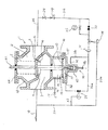
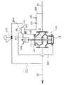
この発明の参考例1を図1と図2により説明する。開閉弁本体1は一次側配管20と二次側配管30との間に接続され、この開閉弁本体1のケーシング40は、この一次側配管20が連通する一次流路2と、二次側配管30が連通する二次流路3と、この二次流路3に隣接する、例えば下方に位置するピストン室10とで構成されている。
【0008】
開閉弁本体1には一次流路2と二次流路3を連通せしめる連通口4が形成されている。この連通口4の上縁部には弁主体5が着座する弁座6が形成されている。この弁主体5の上面には、一次流路2を介して対向するケーシング40の天蓋44との間に装着されたスプリングSが圧接されており、下面には開弁時流量を緩やかに上げるためテーパ状のスカート7を備えている。
【0009】
弁主体5と二次流路3を介して対向するピストン室10には、弁主体5とステム12を介して連結していると共に、弁主体5よりも大きな受圧面積を持つ制御ピストン11が嵌着されている。ピストン室10はこの制御ピストン11により下方を加圧室13、上方を減圧室14に仕切られ、これら両室13、14は制御ピストン11に形成された小径の脱気孔15により連通されている。ケーシング40の一部である減圧室14の壁部には脱気孔15より大きな流過面積を持つ排水弁17付きの排水管16が接続されている。なお、この排水弁17は常時開である。
【0010】
加圧室13の底部はケーシング40の底部開口部を塞ぐピストン室蓋体41で形成されている。この蓋体41の中央下面には、制御ピストン11より下方に突出したステム12の下端を受け入れ、かつ開度調整用ポジショナ50の胴部51を嵌着する有底筒状の突出部42が形成されている。
【0011】
この開度調整用ポジショナ50は、有底円筒状の胴部51と、この胴部51の下部から胴部51と同軸で突出し蓋体41の突出部42の底部に形成した雌ネジ孔42bに螺入した長ネジ部55とで構成されている。この長ネジ部55の下端にスパナ掛け用の把持部56が形成され、長ネジ部55にはロックナット43が蓋体41の突出部42の外側に螺装されている。
【0012】
開度調整用ポジショナ50の胴部51の中間位置には胴部51の径より僅かに小さい小径部54が形成され、突出部42に嵌着した時にこの小径部54の周囲に空間部53が形成される。一方胴部51の内部にはシリンダ室52が形成され、このシリンダ室52と空間部54を連通するシリンダ孔54aが小径部54に形成されている。
【0013】
シリンダ室52の上端開口部にはステム12の下端部12aが挿通可能で、弁主体5が開弁することに伴ってOリングが装着可能に加工形成された下端部12aが通過する時シリンダ室52と加圧室13が連通しないように、シリンダ室52よりも小径のシリンダ開口部52aを形成している。下端部12aの上方には、シリンダ開口部52aよりも小径で十分な長さのステム首部12bを加工形成している。これによって、開度調整用ポジショナ50と突出部42とが半開維持手段を構成する。
【0014】
突出部42の側部には空間部53に連通する一次圧孔h1が形成され、蓋体41には加圧室13に連通する加圧室孔h2が形成されている。 なお、ステム12の上端12cは、弁主体5の上面から突出し天蓋44をパッキンを介して貫通しインジケータとして弁の開度を示すようになっている。
【0015】
さて、一次圧孔h1は一次側配管20とは遠隔起動用電磁弁25の付いた導圧管26を介して接続されている。導圧管26には一次圧孔h1に向かって一次側配管20から順に、メンテナンス弁28、ストレーナ29、遠隔起動用電磁弁25、この電磁弁25に並列配置の現場手動起動弁32、二次圧設定用パイロット弁34、オリフィス31が接続されている。また、このオリフィス31と一次圧孔h1の間で分岐した導圧分管26aが、再開弁手段としての充水感応用パイロット弁33を介して加圧室孔h2に接続されている。
【0016】
なお、遠隔起動用電磁弁25および現場手動起動弁32、そして充水感応用パイロット弁33は常時閉である。また、メンテナンス弁28、二次圧設定用パイロット弁34は常時開である。 二次配管30と充水感応用パイロット弁33の感圧部とは感圧管23を介して接続されている。この充水感応用パイロット弁33と感圧管23とは充水検知手段を構成する。また、二次配管30と二次圧設定用パイロット弁34の感圧部とは、感圧管23およびこの感圧管23から分岐した感圧分岐管23aを介して接続されている。
【0017】
二次圧設定用パイロット弁34は、常時開弁状態で、パイロット弁34の感圧部に送られる圧力が設定値になると閉じられる弁であり、また充水感応用パイロット弁33は、常時閉弁状態で、感圧部に送られる圧力が設定値になると開かれる弁である。これらのパイロット弁は一般のものであるが、二次圧設定用パイロット弁34や充水感応用パイロット弁33の構造は、たとえば特願平9−335846号に記載の全開補助パイロット弁30と調圧パイロット弁25の構造をそれぞれ用いることができる。以下の実施形態に用いられるパイロット弁についても同様である。
【0018】
次に、本参考例1の作動について説明するが、まず開閉弁装置を開く場合について詳説する。 図示しない火災感知器からの火災信号を受けて、図示しない制御装置は遠隔起動用電磁弁25に開弁信号を送出する。遠隔起動用電磁弁25が開かれると、一次側配管20の消火水は、導圧管26を通って遠隔起動用電磁弁25、二次圧設定用パイロット弁34、オリフィス31を通り突出部42の一次圧孔h1から入って、空間部53、シリンダ孔54a、シリンダ室52、シリンダ開口部52aと順次通過して加圧室13に加圧給水される。なお、図1および図2は、起動弁25が開かれた直後の状態を示している。
【0019】
当初は弁主体5は閉止状態なので、ステム12の下端部12aは開度調整用ポジショナ50のシリンダ室52の中に入っていて、シリンダ開口部52aの所にはステム首部12bが位置しており、このためシリンダ室52と加圧室13は連通状態になっている。
【0020】
加圧室13に加圧給水された消火水は加圧室13内の空気を脱気孔15から減圧室14に排出させ、加圧室13内が充水した後は消火水が脱気孔15から減圧室14に流れ込み、減圧室14が充水した後は消火水は排水管16から排水される。この際、加圧室13が充水した時点で、弁主体5の受圧面積よりも大きな受圧面積を持つ制御ピストン11は消火水の一次圧を下面に受け、弁主体5にかかる消火水の一次圧とスプリングSの圧接力や摩擦力や弁主体5等の自重に抗して、制御ピストン11を押し上げる。これによって、ステム12を介して弁主体5は上に押し上げられる。
【0021】
弁主体5が開き始めると一次流路2内の消火水は二次流路3を介して二次側配管30に流れ込む。消火水が更に加圧室13に給水され、制御ピストン11が上昇するのに伴い、ステム12の下端部12aが上昇しシリンダ開口部52aに位置すると、下端部12aの弁体としての機能によりシリンダ開口部52aを封止し、シリンダ室52と加圧室13は流路が絶たれる。
【0022】
すると、消火水は加圧室13には給水されなくなり加圧室13の圧力は脱気孔15および排水管16から逃げるので、弁主体5にかかる一次圧とスプリングS等の下向きの力により弁主体5は閉止方向へ動くようになる。すると、下端部12aがシリンダ開口部52aから離れて、シリンダ室52から加圧室13への消火水の給水が開始され、再び上昇し始めて弁主体5は開弁方向に動く。
【0023】
このようなことが繰り返されるため、弁主体5は開度調整用ポジショナ50によって調整されたシリンダ開口部52aの高さ位置で、半開状態のまま開弁動作が一旦停止する。なお、半開状態とは、弁主体5が全開に至らない状態で過剰なウォータハンマが発生せず、かつある程度二次側配管30への流量も確保できる開度に弁主体5が開いている状態をさす。この開度は、ポンプ設備容量や二次側配管条件などその現場設備条件によって様々であり、それに対し開度調整用ポジショナ50によってそれぞれ最適な開度に調整できる。
【0024】
このように半開維持状態で二次側配管30に充水されていくと、次第に二次側の圧力が増して行き、この二次圧が予め設定しておいた充水感応用パイロット弁33の設定値、例えば2キログラム毎平方センチメートル(以降kg/cm2と表示)を越えると充水したものとみなす。そしてこの時、二次側配管の圧力は感圧管23を介して伝わり、パイロット弁33が開弁し、導圧分岐管26aを介して加圧室孔h2を通り加圧室13に給水される。すると、再び弁主体5は開弁方向(上方)に動き始める。
【0025】
弁主体5の開度が大きくなり二次圧が高くなって、二次圧が二次圧設定用パイロット弁34の設定圧力、例えば5kg/cm2を越えると、この圧力が感圧管23および感圧分岐管23aを介して二次圧設定用パイロット弁34の感応部に伝わるので、このパイロット弁34が絞られて加圧室13への給水が少なくなる。その給水流量が、脱気孔15からの排水流量よりも少なくなってくると、制御ピストン11および弁主体5は全開方向への上昇を止めて下降に転じる。このようになると、開閉弁本体1の流量が減じて来るので、二次圧が下がりだす。
【0026】
また、逆に二次圧が設定圧力5kg/cm2より低くなれば、この圧力が感圧管23等を介して伝わり、パイロット弁34が開き出し、加圧室13への給水流量が脱気孔15からの排水流量よりも多くなってきて、制御ピストン11および弁主体5は閉弁方向への下降を止めて上昇を始め、開閉弁本体1の流量が増加してきて、二次圧が上がりだす。結局、二次圧は設定圧力の前後を維持する。このようにして、二次圧設定用パイロット弁34により二次側の圧力が調整される。
【0027】
ところで、上記のような開閉弁装置の消防用設備をもつプラント防災設備においてその管路条件やポンプ設備容量などに応じて半開維持状態つまり一時停止状態の開度を現場などで変えたい場合がある。
【0028】
その場合は、開度調整用ポジショナ50のロックナット43を緩めて把持部56をスパナ等で回しシリンダ開口部52aの高さ位置を調整する。すなわち、一時停止開度を大き目にとりたい場合は把持部56を右に回して、開度調整用ポジショナ50を雌ネジ孔42bにねじ込むようにして上昇させ高く設定し、逆に開度を小さ目にとりたい場合は把持部56を左に回して、開度調整用ポジショナ50を下降させ低く設定し、決定した所でロックナット43を締める。なお、把持部56と長ネジ部55と雌ネジ孔42bとで維持開度設定手段を構成している。
【0029】
次に、開閉弁を閉じる場合について説明する。図示しない制御装置が操作されて、この制御装置は遠隔起動用電磁弁25に閉弁信号を送出する。遠隔起動用電磁弁25が閉じられると、一次側配管20の消火水は、シリンダ室52及び加圧室13への給水を停止する。すると、加圧室の圧力は排水外圧すなわち大気圧とほぼ等しくなるので、弁主体5の一次側圧力と二次側圧力との差圧力およびスプリングSの圧接力で弁主体5が押し下げられる。加圧室13内の消火水は脱気孔15を通って減圧室14に移動し、弁主体5は弁座6に着座し全閉される。
【0030】
また、弁主体5の閉弁により二次側配管30の二次圧が減圧するので、この二次圧が充水感応用パイロット弁33の設定値より低くなると充水感応用パイロット弁33が閉じられて、この充水感応用パイロット弁33も元の状態に戻る。
【0031】
上記のように、弁本体5を開度調整用ポジショナ21で適切な半開維持状態に設定でき、二次圧が所定圧以上になると、弁本体が全開となるので、ウオーターハンマ現象は防止でき、二次側への充水も遅れることも少なく達成できる。
【0032】
次にこの発明の参考例2を図3と図4により説明するが、参考例1と同一図面符号はその名称も機能も同一である。
【0033】
開閉弁本体100において参考例1の開閉弁本体1と異なるのは、参考例1が、開閉弁本体1のステム12の下端が制御ピストン11から下方に突出してかつ加工形成されており、また、ピストン室蓋体41に突出部42が形成されているのに対し、参考例2が、ステム112の下端が制御ピストン11から下方に大きく突出せず、かつ参考例1のステム首部12bなどのようには加工形成されてはいないことと、ピストン室蓋体141には突出部が形成されていないこと、すなわち開度調整用ポジショナ50が内臓されていない事である。
【0034】
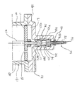
参考例2では、半開維持手段としての開度調整用ポジショナ装置160が別体となっており、この開度調整用ポジショナ装置160の筐体140は、開閉弁本体100の天蓋44に取り付けられた支持体STに、筐体140に設けられた支持部141が固定されている。筐体140は有底円筒状で下底144に開けられたステム孔144aに、天蓋44から貫通突出するステム112がパッキン等の水密構造を介して貫入している。
【0035】
筐体140の中に円筒状に形成された円筒室145には開度調整用ポジショナ150の有底筒状の胴部151が嵌着されており、この胴部151の内部に形成されたシリンダ室152の下端のシリンダ開口部152aがステム112の上端112bを嵌挿できるように設けられている。開度調整用ポジショナ150の上底には上端に把持部156を形成した長ネジ部155を突設しており、この長ネジ部155は筐体140の上底143に形成した雌ネジ孔143aに螺入している。
【0036】
なお、上記のステム112、シリンダ室152、胴部151、円筒室145、長ネジ部155、雌ネジ孔143aは、図4に示すように全て同軸に位置している。また筐体140の外部の長ネジ部155にはロックナット146が螺装されている。
【0037】
胴部151の中央部にはその上下端の外径よりも若干小さく形成された小径部154があり、円筒室145に嵌着している時はこの円筒室145の壁面との間に胴部151の中央側面全周に空間部153を形成する。小径部154にはこの空間部153とシリンダ室152とを連通するシリンダ孔154aが設けられ、筐体140の側部142には空間部153と連通する連通孔h3が設けられている。また筐体140の下部壁面にはステム112の臨む円筒室145、すなわちステム室145aに連通する加圧孔h4が設けられている。
【0038】
さて、連通孔h3は第一の導圧管120を介して一次側配管20に接続されている。第一の導圧管120には連通孔h3に向かって一次側配管20から順に、起動弁130、オリフィス131が接続されている。加圧孔h4は第二の導圧管121を介して開閉弁本体100の加圧室13に接続されている。
【0039】
また、第二の導圧管121は途中で導圧分管122に分岐し、導圧分管122は再開弁手段としての充水感応用パイロット弁132を介して第一の導圧管120に接続されている。この充水感応用パイロット弁132の感圧部には感圧管123を介して二次側配管30が接続されている。なお、この充水感応用パイロット弁132は常時閉で、感圧部が設定された圧力を越えた時に開弁する。また、充水感応用パイロット弁132と感圧管123とは充水検知手段を構成する。
【0040】
一時停止の開度を変えたい場合は、開度調整用ポジショナ150のロックナット146を緩めて把持部156をスパナ等で回しシリンダ開口部152aの高さ位置を調整する。調整後ロックナット146を締めて固定する。なお把持部156と長ネジ部155と雌ネジ孔143aとで維持開度設定手段を構成している。また、支持体STとの取付高さを変えることでも維持開度を設定することができる。
【0041】
次に上記参考例2の作動を説明する。図3および図4は、起動弁130が開かれた直後の状態を示している。 図示しない火災感知器からの火災信号を受けた図示しない制御装置により開弁信号が送られ常時は閉の起動弁130が開かれると、一次側配管20の消火水は第一の導圧管120を通り起動弁130、オリフィス131、連通孔h3、空間部153、シリンダ孔154a、シリンダ室152、ステム室145a、加圧孔h4、第二の導圧管121と、順次通過して加圧室13に給水される。
【0042】
加圧室13に給水されると制御ピストン11が押し上げられ、制御ピストン11に接続されているステム112を介して連結された弁主体5が開き始めると一次側配管20内の消火水は連通口4を介して二次側配管30に流れ込む。
【0043】
消火水が更に加圧室13に給水され制御ピストン11が上昇するのに伴い、ステム上端112bが上昇しシリンダ開口部152aに位置すると、ステム上端112bがシリンダ開口部152aを封止し、ステム室145aに消火水がいかなくなり、加圧室13への流路が絶たれる。これによって、加圧室13の圧力がなくなるので弁主体5は閉止方向へ動き始める。すると、ステム上端112bがシリンダ開口部152aから離れて、シリンダ室152から加圧室13への給水が開始され、再び弁主体5は上昇し始めて開弁方向に動く。
【0044】
このようなことが繰り返されるため、弁主体5は開度調整用ポジショナ150のシリンダ開口部152aの高さ位置とステム上端112bとの関係によって、半開状態で開弁動作が一旦停止する。
【0045】
半開維持状態で二次側配管30に給水されると、次第に二次側配管30の水圧、すなわち二次圧が増して行き、この二次圧が予め設定しておいた充水感応用パイロット弁132の設定値、例えば2kg/cm2を越えると、二次圧が感圧管123を介してパイロット弁132に伝わるのでこのパイロット弁132が開弁する。すると一次側の消火水は第一の導圧管120を通り起動弁130、オリフィス131、導圧分管122、充水感応用パイロット弁132、第二の導圧管121を介して加圧室13に給水される。
【0046】
開弁動作がいったん停止していた弁主体5は更に開弁方向(上方)に動き始める。弁主体5の開弁により二次圧が設定圧2kg/cm2より下がる事はないので、充水感応用パイロット弁132は閉止されず給水を続けるため、開弁動作は全開までに至る。
【0047】
ところで、半開維持状態つまり一時停止の開度を変えたい場合は、開度調整用ポジショナ150のロックナット146を緩めて把持部156をスパナ等で回しシリンダ開口部152aの高さ位置を調整する。決定した所でロックナット146を締める。
【0048】
なおこの開度調整用ポジショナ150ではねじで高さ位置を変えるようにしているが、それに限らずいかなる機構を使ってもよい。また、ポジショナ150の高さを変えずに、支持体STとの高さ位置をスライド固定可能な構造にして、アジャストするようにしてもよい。
【0049】
その後、図示しない制御装置が操作されて閉弁信号が送られ起動弁130が閉じられると、一次側配管20からの導圧管120,121、導圧分管122、充圧感応用パイロット弁132を介した加圧室13への給水が停止され、加圧室13の圧力はなくなるので、一次圧などが弁主体5を閉弁方向に押して弁主体5は閉弁に至る。
【0050】
一方、弁主体5とともにステム112が下がり、ステム上端112bがシリンダ開口部152aから離れて、二つの導圧管120、121がシリンダ室152を介して連通状態になって、開度調整用ポジショナ装置160が復旧する。また、弁主体5の閉弁により二次側配管30の二次圧が減圧するので、この二次圧が充水感応用パイロット弁132の設定値より低くなると充水感応用パイロット弁132が閉じられて、この充水感応用パイロット弁132も元の状態に戻る。
【0051】
この参考例2は上記のように構成したので、開閉弁本体100が特製品である必要がなく、一般の弁を用いる事ができる。すなわち、弁の天蓋や隣接する壁などに支持体を介して開度調整用ポジショナ装置160を固定し、天蓋から突出するステム上端をそのまま、または径が合うようにアダプタを作りステム上端に挿入固定すればよい。このように、既存の開閉弁を取り替えることも、加工することもなくそのまま利用できる。
【0052】
また、参考例1のように維持開度設定手段を開閉弁下端にではなく開閉弁の上端に設けたので開度設定操作がかなり容易である。また、重量物の開閉弁を組み付ける際に下端を損傷しないように気遣う必要もなく、本体の高さも不要に高く配置することもないので組み付けが楽である。
【0053】
上記のように、弁本体5を開度調整用ポジショナ150で適切な半開維持状態に設定でき、二次圧が所定圧以上になると、弁本体が全開となるので、ウオーターハンマ現象は防止でき、二次側への充水も遅れることも少なく達成できる。
【0054】
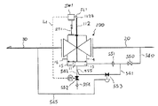
次にこの発明の実施形態1を図5と図6により説明するが、参考例1および参考例2と同一図面符号はその名称も機能も同一である。 実施形態1では、ステム12の下端部12aや上端112bを弁体として扱うのではなく、ステム112に取り付けたインジケータ250の動きを捉えたロッド248を介して加圧室13への流れを制御したものである。
【0055】
開閉弁本体100の天蓋44から上方へ貫通突出するステム112には、上方に小径となるテーパ部251とこのテーパ部251の下に接続する円筒部252と任意の高さ位置でステム112に固定する止めネジ253等の固定手段とで構成するインジケータ250が取り付けられている。
【0056】
弁本体100のステム112に固定した弁主体5の全閉位置でインジケータ250のテーパ部251に近接し、弁主体5の半開停止開度位置でテーパ部251に当接するロッド頭部249を備えたロッド248が、水撃防止用パイロット弁240の、パッキンを介したロッド孔241cに摺動可能に装着されている。
【0057】
パイロット弁240は、ロッド248が臨むロッド室247と、パイロット弁体244およびスプリングS0を備えた弁室242とから構成され、これらのロッド室247と弁室242は連通口246により連通している。なお、パイロット弁240の本体241は天蓋44に支持体STを介して固定されている。
【0058】
弁室242では、パイロット弁体244が、スプリングS0により閉弁方向に連通口246の周囲に形成した弁座245に圧接されている。ロッド室247では、ロッド頭部249に対する他端であるロッド248の先端が、連通口246に臨み、かつ連通口246を常時閉状態を保つパイロット弁体244に近接または当接している。
【0059】
弁室242は一次圧孔h5により逃がし配管222に連通しており、ロッド室247は逃がし孔h6により第二逃がし配管223に連通している。この第二逃がし配管223には、二次側配管30に感圧管224を介して感圧部に連通する、再開弁手段としての充水感応用パイロット弁232が接続され、充水感応用パイロット弁232を介して大気開放されている。
【0060】
一次圧孔h5は逃がし配管222とこの逃がし配管222の分岐元である導圧管220とを介して一次側配管20に接続されている。この導圧管220は一次側配管から順に起動弁230、オリフィス231が接続されており、逃がし配管222が分岐する一方で、導圧管221が加圧室13に接続されている。
【0061】
なお、上記充水感応用パイロット弁232は、第二逃がし配管223ではなく、図5の点線で示すように逃がし配管222の方に接続してもよい。充水感応用パイロット弁232は常時開弁状態で、感圧部に設定圧以上の圧力が入ると閉弁する。水撃防止用パイロット弁240は常時閉弁状態であり、ロッド248がパイロット弁体244を弁室242側に押圧移動することにより開弁する。
【0062】
なお、インジケータ250と、ロッド248を含めた水撃防止用パイロット弁240とは、半開維持手段を構成する。また、止めネジ253により任意に高さを設定できるインジケータ250は維持開度設定手段として働く。
【0063】
次に上記実施形態1の作動を説明する。図5および図6は、起動弁230が開かれた直後の状態を示している。 図示しない火災感知器からの火災信号を受けた図示しない制御装置により開弁信号が送られ常時閉の起動弁230が開かれると、一次側配管20の消火水は導圧管220を通りオリフィス231を通過して加圧室13に給水される。
【0064】
すると前述の第2の参考例と同様な動作をして、弁主体5が開き始めると一次側配管20の消火水は二次側配管30に流れ込む。この時、弁主体5に連結されたステム112に固定されたインジケータ250も上昇するが、テーパ部251に近接しているロッド頭部249には、まだ接しない。
【0065】
弁主体5が更に上昇すると、インジケータ250が上昇し、テーパ部251にロッド頭部249が当接して、その後テーパ部251によりロッド頭部249を介してロッド248をロッド孔241c内に押し入れていく。すると、ロッド248の先端に当接しているパイロット弁体244は、ロッド248によりスプリングS0の圧接力と、一次側の圧力がパイロット弁体244を押す力とに抗して押されることにより移動して開弁する。
【0066】
これによって、弁室242とロッド室247とが連通口246を介して連通し、逃がし配管222から供給されていた導圧管220の一次圧は、一次圧孔h5、弁室242、連通口246、ロッド室247、逃がし孔h6、第二逃がし配管223を介し充水感応用パイロット弁232に至り、二次圧が設定圧以下なので開弁している充水感応用パイロット弁232を介して大気に逃がされる。
【0067】
よって、逃がし配管222の減圧によって逃がし配管222から分岐した導圧管221を介して加圧室13が減圧され、弁主体5は閉弁方向に動き始めるので、ステム112およびインジケータ250のテーパ部251が下降し始め、ロッドはスプリングS0等に押されて、ロッド頭部249はテーパ部251の斜面を摺動しながら押し戻される。すると、充水感応用パイロット弁232の弁体244が閉弁し始め、導圧管220からの一次圧は連通口246から逃がされなくなるので、加圧室13の圧力が導圧管220、221から一次圧を供給されて上昇し、弁主体5が開弁方向へと動き始める。
【0068】
以上のことが繰り返されるため、弁主体5はインジケータ250とロッド頭部249とが当接する位置に依存した形で、半開状態で開弁動作が一旦停止する。
【0069】
半開維持状態で二次側配管30に給水されると、次第に二次側配管30の水圧、すなわち二次圧が増して行き、この二次圧が予め設定しておいた充水感応用パイロット弁232の設定値、例えば2kg/cm2を越えると、二次圧が感圧管224を介して充水感応用パイロット弁232に伝わるのでこのパイロット弁232が閉弁する。なおこの充水感応用パイロット弁232と感圧管224とは充水検知手段を構成する。
【0070】
充水感応用パイロット弁232が閉弁することによって、導圧管220で加圧室13に供給されていた圧力は、逃がし配管222等を通して逃がされる事がなくなるので、一次側の圧力消火水は導圧管220を通り起動弁230、オリフィス231、導圧管221を通って加圧室13に給水される。
【0071】
すると、再び弁主体5は開弁方向(上方)に動き始める。弁主体5の開弁により二次圧が設定圧2kg/cm2より下がる事はないので、充水感応用パイロット弁132は閉止されず給水を続けるため、開弁動作は全開までに至る。
【0072】
消火が終了し、図示しない制御装置が操作されて閉弁信号が送られ起動弁230が閉じられると、一次側配管20からの加圧室13への給水が停止され、加圧室13の圧力はなくなり、一次圧などが弁主体5を閉弁方向に押すので弁主体5は閉弁に至る。
【0073】
一方、インジケータ250がステム112と共に下がり、ロッド248のインジケータ250による押し込みが解除され、ロッド248がスプリングS0により押し戻され、パイロット弁体244は閉弁する。また、弁主体5の閉弁により二次側配管30の二次圧が減圧し、この二次圧が充水感応用パイロット弁232の設定値より低くなって充水感応用パイロット弁232が開かれ元の状態に戻る。このようにして水撃防止用パイロット弁240は復旧される。
【0074】
この実施形態1は上記のように構成したので、開閉弁本体100が特製品である必要がなく、一般の弁を用いる事ができる。すなわち、弁の天蓋や隣接する構造体などに支持体を介して水撃防止用パイロット弁240を固定し、天蓋から突出するステムにインジケータ250を取り付けるとよい。このように、既存の開閉弁を取り替えることも、加工することもなくそのまま利用できる。
【0075】
なお、維持開度設定手段の他の例として、ステムにはインジケータではなく、傾斜を有する板をロッド頭部に対し適切に取りつけるようにしてもよい。また、ステムとロッドをリンクで連結してステムの上昇によってロッドが押し込まれるように構成してもよい。このときステム側のリンクの取り付け高さを調整できるようにしたり、リンクを伸縮設定可能にしたり、支持体STの位置を上下水平に位置設定可能にしてもよい。
【0076】
また、ステムがある位置まで上昇したときスイッチが押され、このスイッチが押されている間パイロット弁体244が開弁しスイッチが押されなくなったときパイロット弁体244が閉弁するような電磁弁構造を有する水撃防止用パイロット弁240としてもよい。このときスイッチの高さ位置を調整するようにすればよい。
【0077】
上記のように、弁本体5を、ステム112に取り付けたインジケータ250と水撃防止用パイロット弁240の取付け高さとで、適切な半開維持状態に設定でき、二次圧が所定圧以上になると、弁本体5が全開となるので、ウオーターハンマ現象は防止でき、二次側への充水も遅れることも少なく達成できる。
【0078】
次にこの発明の参考例3を図7と図8により説明するが、参考例1、2また実施形態1と同一図面符号はその名称も機能も同一である。
【0079】
参考例3は、実施形態1のようにインジケータ250の動きを捉えたロッド248を介して加圧室13への流れを制御したものであるが、加圧室13への供給圧力の圧抜き管路の開放制御をするのではなく、供給管路を閉止制御するものである。また、再開弁機構は、二次圧制御パイロット弁で圧抜き管路を遮断するのではなく、二次圧制御パイロット弁で供給管路を開放制御するものである。
【0080】
開閉弁本体100のステム112に固定した弁主体5の全閉位置でインジケータ250のテーパ部251に近接し、弁主体5の半開停止開度位置でテーパ部251に当接するロッド頭部361を備えた閉弁ロッド360が、パッキンを介して水撃防止用パイロット弁340のロッド孔341aに摺動可能に装着されている。なおこのロッド頭部361は水平な軸を介して閉弁ロッド360に容易に回転するローラーとして形成されている。
【0081】
この水撃防止用パイロット弁340の本体341は、設けられた支持部348が天蓋44に支持体STを介して固定されている。水撃防止用パイロット弁340は、弁室343と一次圧室342と排水室347と開弁ロッド加圧室346とが順に連なるように構成されている。
【0082】
弁室343の外壁には加圧室13と第二の導圧管321を介して接続される弁室孔h8が形成され、一次圧室342の外壁には一次側配管20に第一の導圧管320を介して連通するよう接続される連通孔h7が形成され、排水室347の外壁には大気に開口する逃がし孔341bが形成され、開弁ロッド加圧室346の外壁には二次側配管30と常時閉の充水感応用パイロット弁332を設けた感圧管322を介して連通するよう接続される感圧孔h9が形成されている。なお、第一の導圧管320には常時閉の起動弁330とオリフィス331とが接続されている。
【0083】
一次圧室342と弁室343とを仕切る隔壁345には両室342、343を連通させる連通口345aが設けられており、この連通口345aの周囲の弁室側に形成された円筒部345bの端縁が、水撃防止用パイロット弁340の弁体353を着座させる弁座345cとして形成されている。
【0084】
弁室343には、弁体353と、一端がこの弁体353の着座面側に装着圧接し他端が円筒部345bを遊嵌するとともに隔壁345に圧接するスプリングS2と、一端が弁体353の着座面の反対面に嵌着圧接し、他端が弁室343に臨む閉弁ロッド360の先端に設けられた座板362に圧接するスプリングS3と、が備えられている。通常時、すなわち開閉弁本体100が閉じている時は、弁体353はスプリングS2、S3に支持されて着座しておらず、常時は開の状態を保っている。
【0085】
一次圧室342には、排水室347との間に仕切られた隔壁344に形成された貫通孔344aにパッキンを介して貫通し先端が連通口345aに及ぶ開弁ロッド351が臨んでいる。この開弁ロッド351は、後端に、排水室347と開弁ロッド加圧室346とを仕切る開弁ピストン352が連結している。この開弁ピストン352には排水室347と開弁ロッド加圧室346とを連通し逃がし孔341bよりも小さな孔352aが形成されている。
【0086】
排水室347には、開弁ロッド加圧室346が無圧の時つまり通常時に、開弁ロッド351の先端が弁座345cよりも弁体353側に突出しないよう付勢または当接するスプリングS1を、隔壁344と開弁ピストン352の間に装着している。
【0087】
なお、感圧管322と充水感応用パイロット弁332とは充水検知手段を構成する。インジケータ250と、ロッド360を含めた水撃防止用パイロット弁340とは、半開維持手段を構成する。また、充水感応用パイロット弁332は再開弁手段として働く。また、止めネジ253により任意に高さを設定できるインジケータ250は維持開度設定手段として働く。
【0088】
次に上記参考例3の作動を説明する。図7および図8は、起動弁330が開かれた直後の状態を示している。 図示しない火災感知器からの火災信号を受けた図示しない制御装置により開弁信号が送られ常時は閉の起動弁330が開かれると、一次側配管20の消火水は第一の導圧管320を通り起動弁330、オリフィス331、連通孔h7、一次圧室342、連通口345a、弁室343、弁室孔h8、第二の導圧管321、を順に通り、加圧室13に給水される。
【0089】
すると上記参考例2と同様な動作をして、弁主体5が開き始めると一次側配管20の消火水は二次側配管30に流れ込む。この時、弁主体5に連結されたステム112に固定されたインジケータ250も上昇するが、テーパ部251に近接しているロッド頭部361には、まだ接しない。
【0090】
消火水が更に加圧室13に給水され、制御ピストン11が更に上昇すると、インジケータ250が上昇し、テーパ部251にロッド頭部361が当接して、その後テーパ部251によりロッド頭部361を介して停止ロッド360をロッド孔341aに押し入れていく。すると、停止ロッド360の先端に設けられた座板362を押圧してスプリングS3、S2を圧縮させる。インジケータ250が上昇してロッド頭部361が円筒部252に至る前に、弁体353が弁座345cに着座し、導圧管320,321の加圧室13への給水は断たれる。
【0091】
すると、インジケータ250が下降して、停止ロッド360がスプリングS3、S2の圧接力により押し戻され、弁体353が開弁し、導圧管320,321より加圧室13へ給水され、再びインジケータ250が上昇する。
【0092】
このようなことが繰り返されるため、弁主体5はロッド頭部361が押圧されて弁体353が閉弁するインジケータ250の位置に調整することで、半開状態で開弁動作が一旦停止する。
【0093】
半開維持状態で更に二次側配管30に給水されると、次第に二次側配管30の圧力、すなわち二次圧が増して行き、この二次圧が予め設定しておいた充水感応用パイロット弁332の設定値、例えば2kg/cm2を越えると、二次圧が感圧管322を介して充水感応用パイロット弁332に伝わるのでこのパイロット弁332が開弁する。
【0094】
すると、感圧管322を通って二次側の消火水が開弁ロッド加圧室346に充水し、開弁ピストン352をスプリングS1や摩擦力に抗して押圧し弁体353側に移動させる。これに伴い開弁ロッド351の先端が着座している弁体353の中央部を突き押し、更にスプリングS3の圧接力にも抗して弁体353を強制的に押し開き開弁に至らせる。なお、感圧管322からの給水流量は、孔352aを通り排水室347から逃がし孔341bへ排水される流量よりも大きい。
【0095】
弁体353が開弁すると、一次側の圧力消火水は導圧管320、321を通り加圧室13に給水され、再び弁主体5は開弁方向(上方)に動き始める。弁主体5の開弁により二次圧が設定圧2kg/cm2より下がる事はないので、充水感応用パイロット弁332は閉止されず給水を続けるため、弁主体5の開弁動作は全開までに至る。
【0096】
その後、図示しない制御装置が操作されて閉弁信号が送られ起動弁330が閉じられると、一次側配管20からの導圧管320、321、水撃防止用パイロット弁340を介する加圧室13への給水が停止され、加圧室13の圧力はなくなるので、一次圧などが弁主体5を閉弁方向に押すため弁主体5は閉弁状態に戻る。 一方インジケータ250がステム112と共に下がるので、ロッド360のインジケータ250による押し込みが解除され、ロッド360がスプリングS2,S3により押し戻され、水撃防止用パイロット弁340の弁体353が常時開弁状態となる。また弁主体5の閉弁により二次側配管30の二次圧が減圧し、充水感応用パイロット弁332の設定値より低くなって充水感応用パイロット弁332が閉じられると、開弁ロッド加圧室346は孔352aと逃がし孔341bを通して大気圧となるので、開弁ロッド351はスプリングS1により弁体353から離れる方向に押し戻され、水撃防止用パイロット弁340は復旧する。
【0097】
この参考例は上記のように構成したので、開閉弁本体100が特製品である必要がなく、既存の開閉弁を取り替えることも、加工することもなくそのまま利用できる。
【0098】
上記のように、弁本体5を、ステム112に取り付けたインジケータ250と水撃防止用パイロット弁340の取付け高さとで、適切な半開維持状態に設定でき、二次圧が所定圧以上になると、弁本体5が全開となるので、ウオーターハンマ現象は防止でき、二次側への充水も遅れることも少なく達成できる。
【0099】
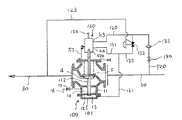
次にこの発明の参考例4を図9と図10により説明するが、参考例3と同一図面符号はその名称も機能も同一である。本参考例4は、参考例3で、外付けされた充水感応用パイロット弁の機能を水撃防止用パイロット弁に内臓させたものである。
【0100】
水撃防止用パイロット弁440は、弁室343と一次圧室342と排水室347と開弁ロッド加圧室346と二次側受圧室448と調圧室449とが順次連なるように構成されている。弁室343と一次圧室342と排水室347は参考例3と同構成で、外部とも同じ連通状態を形成している。二次側受圧室448の外壁には二次側配管30と感圧管322を介して接続される二次圧孔h10が形成されている。
【0101】
水撃防止用パイロット弁440は、参考例3で記載した構成に加えて、開弁ロッド加圧室346と二次側受圧室448とを仕切るとともに弁孔447aが形成されている隔壁447と、受圧室448と調圧室449とを仕切る弁ピストン456を後端に備え、先端を円錐に形成し弁孔447aに圧接せしめて開弁ロッド加圧室346と二次側受圧室448との連通を遮断する棒状の弁体457と、調圧室449にあって一端を弁ピストン456の後端側に圧接し他端を受け座454に装着したスプリングS4と、先端をこの受け座454の背面中心凹部に摺動圧接し筐体441のネジ孔441aに螺入した調整ボルト453とで構成されている。調整ボルト453には外側にロックナット455が螺装されている。また、調圧室449の外壁には大気に連通する気抜き孔441bが形成されている。
【0102】
なお、感圧管422と、水撃防止用パイロット弁440の二次側受圧室448と調圧室449およびこの二室448,449に含まれる構成は隔壁447を含めて、充水検知手段を構成する。インジケータ250と、ロッド360を含めた水撃防止用パイロット弁440とは、半開維持手段を構成する。また、同時に水撃防止用パイロット弁440は再開弁手段としても働く。また、任意に高さを設定できるインジケータ250は維持開度設定手段として働く。
【0103】
次に上記参考例4の作動を説明する。図9および図10は、起動弁330が開かれた直後の状態を示している。
【0104】
図示しない火災感知器からの火災信号を受けた図示しない制御装置により開弁信号が送られ常時は閉である起動弁330が開かれると、一次側配管20の消火水は第一の導圧管320を通り起動弁330、オリフィス331、連通孔h7、一次圧室342、連通口345a、弁室343、弁室孔h8、第二の導圧管321を順に通り、加圧室13に給水される。
【0105】
すると上記参考例3と同様な動作をして、弁主体5が開き始めると一次側配管20の消火水は二次側配管30に流れ込む。この時、弁主体5に連結されたステム112に固定されたインジケータ250も上昇して、テーパ部251によりロッド頭部361を介して停止ロッド360を押し入れ、座板362を押圧して、弁体353が弁座345cに着座し、導圧管321から加圧室13への給水は断たれる。
【0106】
すると、インジケータ250が下降して、停止ロッド360がスプリングS3、S2の圧接力により押し戻され、弁体353が開弁する。導圧管321より加圧室13へ再び給水され、インジケータ250が上昇する。
【0107】
このようなことが繰り返されるため、弁主体5は、ロッド頭部361が押圧されて弁体353が閉弁するインジケータ250の位置を設定することで、半開状態で開弁動作が一旦停止する。
【0108】
半開維持状態で二次側配管30に給水されると、次第に二次側配管30の圧力、すなわち二次圧が増して行き、この二次圧が感圧管422を介して二次側受圧室448に伝わり、この二次圧が予め設定しておいた調圧室449の設定値、例えば2kg/cm2を越えると、スプリングS4の圧接力と摩擦に抗して弁ピストン456を調圧室449側に動かすので、弁体457の先端が弁孔447aから退いて開弁する。なお、上記調圧室449の設定値を変えたい場合には調整ボルト453を操作する。
【0109】
弁孔447aからの給水流量が、孔352aを通り開弁ロッド加圧室346から排水される流量よりも大きくなったとき、二次側の消火水が開弁ロッド加圧室346に充水し、開弁ピストン352を移動させ開弁ロッド351の先端が弁体353を強制的に押し開き、水撃防止用パイロット弁440を開弁に至らせる。すると、再び弁主体5は開弁方向(上方)に動き始め、その開弁動作は全開までに至る。
【0110】
その後、図示しない制御装置が操作されて閉弁信号が送られ起動弁330が閉じられると、一次側配管20からの導圧管320、321、水撃防止用パイロット弁440を介する加圧室13への給水が停止され、加圧室13の圧力はなくなるので、一次圧などが弁主体5を閉弁方向に押すため弁主体5は閉弁状態に戻る。
【0111】
一方インジケータ250がステム112と共に下がるので、ロッド360のインジケータ250による押し込みが解除され、ロッド360がスプリングS2,S3により押し戻され、水撃防止用パイロット弁440の弁体353が常時開弁状態となる。また弁主体5の閉弁により、二次側配管30の二次圧が減圧し調圧室449の設定値より低くなると、二次側受圧室448が減圧するのでスプリングS4の押圧力により弁体457の先端が弁孔447aを閉止する。
【0112】
すると、開弁ロッド加圧室346内には給水がなくなるので、開弁ロッド351はスプリングS1により弁体353から離れる方向に押し戻され、水撃防止用パイロット弁440は復旧する。
【0113】
この参考例は上記のように構成したので、開閉弁本体100が特製品である必要がなく、既存の開閉弁を加工することもなくそのまま利用できる。また、インジケータ250と水撃防止用パイロット弁440とは、半開維持手段および再開弁手段として働くので、部品数が少なく組み付けが楽である。
【0114】
上記のように、弁本体5を、ステム112に取り付けたインジケータ250と水撃防止用パイロット弁440の取付け高さとで、適切な半開維持状態に設定でき、二次圧が所定圧以上になると、弁本体5が全開となるので、ウオーターハンマ現象は防止でき、二次側への充水も遅れることも少なく達成できる。
【0115】
次にこの発明の参考例5を図11と図6により説明するが、実施形態1と同一図面符号はその名称も機能も同一である。参考例5が実施形態1と異なる点は、導圧管と感圧管及び水撃防止用パイロット弁240に接続する管路系である。
【0116】
導圧管520は一次側配管20から加圧室13に接続されているが、導圧管520の途中には、常時閉の起動弁530、オリフィス531が接続され、オリフィス531に並列に導圧分管521を介した充水感応用パイロット弁533が接続されている。常時閉の充水感応用パイロット弁533の感圧部は感圧管525を介して二次側配管30と接続されている。
【0117】
水撃防止用パイロット弁240の一次圧孔h5には配管523により加圧室13に接続され、逃がし孔h6には逃がし配管524が接続され大気開放されている。感圧管525と充水感応用パイロット弁533は充水検知手段を構成する。インジケータ250と水撃防止用パイロット弁240は半開維持手段を、導圧分管521と充水感応用パイロット弁533とは再開弁手段を、インジケータ250は維持開度設定手段をそれぞれ構成する。
【0118】
次に上記参考例5の作動を説明する。図11は起動弁530が開かれた直後の状態を示している。図示しない火災感知器からの火災信号を受けた図示しない制御装置により開弁信号が送られ常時は閉の起動弁530が開かれると、一次側配管20の消火水は導圧管520およびオリフィス531を通り加圧室13に至る。
【0119】
すると実施形態1と同様な動作をして、弁主体5(図5参照)が開き始めると一次側配管20の消火水は二次側配管30に流れ込み、ステム112に固定されたインジケータ250が上昇して、ロッド248を介して水撃防止用パイロット弁240が強制開弁され一次圧孔h5と逃がし孔h6は連通する。すると、加圧室13の圧力消火水は、配管523、一次圧孔h5、水撃防止用パイロット弁240、逃がし孔h6、逃がし配管524を介して排水される。
【0120】
この排水流量と脱気孔15からの排水流量の和は導圧管520からの給水流量よりも大きく設定すると、その後の作動は順に、加圧室13減圧、制御ピストン11下降、インジケータ250下降、ロッド248押し戻される、水撃防止用パイロット弁240閉弁、加圧室13の配管523からの排水停止、導圧管からの給水による加圧室13の加圧、制御ピストン11上昇、インジケータ上昇…と繰り返され、逃がし配管524、脱気孔15からの排水流量と導圧管520からの給水流量が釣り合ったところでインジケータ250は留まり、従って、弁主体5は、半開状態で開弁動作が一旦停止する。
【0121】
そのあと半開維持状態で二次側配管30に給水されて、この二次側配管圧が設定値を越えると感圧管525を介して充水感応用パイロット弁533が開弁し、導圧管520から加圧室13への給水流量は、オリフィス531からの給水流量に加えて、オリフィス531に並列配置されている充水感応用パイロット弁533からの給水流量が加わるので、水撃防止用パイロット弁240を通した排水流量と脱気孔15からの排水流量の和よりも大きくなり、制御ピストン11は再び全開方向に動き始める。加圧室13へのこの合計供給流量が、最大合計排水流量よりも大きくとれば、その開弁動作は全開までに至る。
【0122】
この参考例は上記のように構成したので、開閉弁本体100が特製品である必要がなく、既存の開閉弁を取り替えることも、加工することもなくそのまま利用できる。
【0123】
弁主体5を閉めたい場合は図示しない制御装置を操作する。すると閉弁信号が送られ起動弁530が閉じられ、一次側配管20からの加圧室13への給水が停止され、加圧室13の圧力はなくなり、一次圧などが弁主体5を閉弁方向に押すので弁主体5は閉弁に至る。するとインジケータ250がステム112と共に下がり、ロッド248のインジケータ250による押し込みが解除され、ロッド248がスプリングS0により押し戻され、水撃防止用パイロット弁240が元の閉弁状態に戻る。
【0124】
また、弁主体5の閉弁により二次側配管30の二次圧が減圧し、この二次圧が充水感応用パイロット弁533の設定値より低くなると、充水感応用パイロット弁533が閉じられ元の状態に戻る。
【0125】
この参考例は上記のように構成したので、開閉弁本体100が特製品である必要がなく、既存の開閉弁を取り替えることも、加工することもなくそのまま利用できる。 また、上記のように、弁本体5を、ステムに取り付けたインジケータ250と水撃防止用パイロット弁240の取付け高さとで、適切な半開維持状態に設定でき、二次圧が所定圧以上になると、弁本体5が全開となるので、ウオーターハンマ現象は防止でき、二次側への充水も遅れることも少なく達成できる。
【0126】
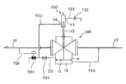
次にこの発明の参考例6を図12により説明するが、参考例5と同一図面符号はその名称も機能も同一である。参考例6が参考例5と共通する点は、開閉弁本体100と一次側配管20と二次側配管30だけである。
【0127】
まず、導圧管540が一次側配管20から常時閉の起動弁550、オリフィス551を介して加圧室13に接続され、加圧室13には排水管542が接続されて、加圧室13の消火水が常時閉の開度維持電磁弁552を介して外部に排出できるようにしている。
【0128】
起動弁550とオリフィス551との間の導圧管540に、加圧室13と排水管542を接続する導圧分管541の途中に、充水感応用パイロット弁553が接続されている。この導圧分管541と排水管542との接続部はy字管555が用いられ、開度維持電磁弁552側の排水管542と導圧分管541との間のなす角は鋭角、たとえば20度をなしている。y字管555の排水管542の下流には開度維持電磁弁552を介して逆止弁554を取り付けている。
【0129】
開閉弁本体100の上面から突出しているステム112の上端112bの軌道内に、常時オフの跳ね返りスイッチSW1のレバー先端SL1があり、上端112bの上昇によってレバー先端SL1が回動する。SW1は、開閉弁本体100に取り付けられた高さ位置調整可能にスライド固定できる支持体SL1に搭載されている。上端112bの上昇通過によりレバー先端SL1は回動しステム112とは摺動状態でオンとなり、上端112bの下降離間によりレバー先端SL1は跳ね戻りオフとなる。このスイッチSW1の信号線L1は開度維持電磁弁552につながれている。
【0130】
支持体SL1は、開閉弁本体100等に固定する取付部と上方に延びる下部スライド部からなる下部品と、スイッチSW1を取り付ける搭載部と下方に延びる長穴付きの上部スライド部からなる上部品との二つの部品からなり、それぞれのスライドを抱き合わせ長穴に挿通したネジで互いに固定して高さ調整するようにしたものである。
【0131】
充水感応用パイロット弁553は常時閉で、その感圧部と二次側配管30とは感圧管545で接続されている。感圧管545と充水感応用パイロット弁553とは充水検知手段を、SW1と信号線L1と開度維持電磁弁552とは半開維持手段を、導圧分管541と充水感応用パイロット弁553とy字管555とは再開弁手段を、支持体ST1は維持開度設定手段を、それぞれ構成している。
【0132】
次に上記参考例6の作動を説明する。図12は起動弁550が開かれた直後の状態を示している。図示しない火災感知器からの火災信号を受けた図示しない制御装置により開弁信号が送られ常時は閉の起動弁550が開かれると、一次側配管20の消火水は導圧管540、起動弁550、およびオリフィス551を通り加圧室13に給水される。
【0133】
すると参考例5と同様な動作をして、弁主体5が開き始めると一次側配管20の消火水は二次側配管30に流れ込み、ステム112が上昇してステム上端112bがスイッチSW1のレバー先端SL1をオン側に倒す。すると、開度維持電磁弁552が開かれ加圧室13の消火水が排水管542を通して排水されるが、給水流量よりも大きな流量で排水されるので、ステム112は下降し始めてステム上端112bがスイッチSW1のレバー先端SL1から離れてオフとなり開度維持電磁弁552が閉となる。すると、また給水流量の方が大きいので、ステム112は上昇し出す。
【0134】
このようなことが繰り返され、レバー先端SL1の回動範囲でステム112が上下動を繰り返し、それに伴って、開閉弁本体100は、上下動しながら半開状態を維持する。
【0135】
このとき、開度維持電磁弁552を通した排水流量と脱気孔15からの排水流量の和は、導圧管540からの給水流量とは、平均的にならすと等しくなる。
【0136】
そのあと半開維持状態で二次側配管30に給水されて、この二次側配管圧が設定値を越えると感圧管525を介して充水感応用パイロット弁553を開弁させる。すると、導圧管540から加圧室13への給水流量は、オリフィス551からの給水流量に充水感応用パイロット弁533からの給水流量が加わるので、開度維持電磁弁552を通した排水流量と脱気孔15からの排水流量の和よりも大きくなり、制御ピストン11は再び全開方向に動き始める。
【0137】
ところで、充水感応用パイロット弁533を通った給水は、排水している排水管542にy字管555を介して逆流するように合流しているため、排水管542を通る排水は充水感応用パイロット弁533を通る給水力によってかなり制限されるか、全く排水しないことになるので、全開までの時間は短い。また排水管542に逆止弁554が取り付けられているので、導圧管540からの加圧室13への給水力が強くても、排水管542の出口で吸引されて加圧室13側に空気が取り込まれることはない。
【0138】
加圧室13への合計供給流量が、最大合計排水流量よりも大きくとれば、その開弁動作は全開までに至る。
【0139】
弁主体5を閉めたい場合は図示しない制御装置を操作する。すると閉弁信号が送られ起動弁550が閉じられ、一次側配管20からの加圧室13への給水が停止され、加圧室13の圧力はなくなり弁主体5は閉弁に至る。
【0140】
一方、弁主体5とともにステム112が下がり、ステム上端112bが跳ね返りスイッチSW1のレバー先端SL1から離れてオフとなり、開度維持電磁弁552を閉に戻す。
【0141】
また、弁主体5の閉弁により二次側配管30の二次圧が減圧し、この二次圧が充水感応用パイロット弁553の設定値より低くなると、充水感応用パイロット弁553が閉じられ元の状態に戻る。
【0142】
この参考例は上記のように構成したので、開閉弁本体100が特製品である必要がなく、既存の開閉弁を取り替えることも、加工することもなくそのまま利用できる。 また、上記のように、弁本体5を、ステム上端12bと跳ね返りスイッチSW1の取付け高さとで、適切な半開維持状態に設定でき、二次圧が所定圧以上になると、弁本体5が全開となるので、ウオーターハンマ現象は防止でき、二次側への充水も遅れることも少なく達成できる。
【0143】
次にこの発明の参考例7を図13と図4により説明するが、参考例2と同一図面符号はその名称も機能も同一である。参考例7が参考例2と異なる点は、導圧分管122が無いこと、加圧室112に排水管を設けたこと、この排水管に充水感応用パイロット弁及びオリフィスを配置したことである。そして更に、開度調整用ポジショナ660においてステム上端112bがシリンダ開口部152aに隙間を設けた点である。
【0144】
まず、起動弁630を設けた第一の導圧管620が一次側配管20と開度調整用ポジショナ装置660の連通孔h3とに接続され、オリフィス632を設けた第二の導圧管621が開度調整用ポジショナ装置660の加圧孔h4と加圧室13とに接続されている。加圧室13はオリフィス633と常時開の充水感応用パイロット弁631とを設けた排水管622に接続され、大気に開放されている。
【0145】
充水感応用パイロット弁631の感圧部と二次側配管30とは感圧管623で接続されている。開度調整用ポジショナ装置660の胴部の内部に形成されたシリンダ室652の下端のシリンダ開口部652aの口径がステム112の上端112bの径よりも少し大きく形成し、シリンダ開口部652aに上端112bが挿入できるように設けられている。
【0146】
感圧管623と充水感応用パイロット弁631とは充水検知手段を、開度調整用ポジショナ装置660は半開維持手段を、充水感応用パイロット弁631が再開弁手段を、それぞれ構成している。
【0147】
次に上記参考例7の作動を説明する。図13は起動弁630が開かれた直後の状態を示している。図示しない火災感知器からの火災信号を受けた図示しない制御装置により開弁信号が送られ常時は閉の起動弁630が開かれると、一次側配管20の消火水は第一の導圧管620を通り、起動弁630、連通孔h3、空間部153、シリンダ孔154a、シリンダ室652、ステム室145a、加圧孔h4、第二の導圧管621、オリフィス632と、順次通過して加圧室13に給水される。
【0148】
この第二の導圧管621からの給水流量は、脱気孔15からの排水流量と排水管622からの排水流量の合計よりも大きく設定されているので、制御ピストン11が押し上げられ、制御ピストン11とステム112を介して連結された弁主体5(図3参照)が開き始めると一次側配管20内の消火水は二次側配管30に流れ込む。
【0149】
弁主体5が更に上昇するのに伴い、ステム上端112bが上昇しシリンダ開口部152aに位置するようになると、ステム上端112bがシリンダ開口部152aに隙間を形成しつつ挿入されるようになり、加圧室13への流路が絞られる。
【0150】
この時の第二の導圧管621からの給水流量は、脱気孔15からの排水流量と排水管622からの排水流量の合計よりも小さく設定されているので、制御ピストン11が下降して弁主体5は閉止方向へ動き始める。すると、ステム上端112bがシリンダ開口部152aから離れて、シリンダ室152から加圧室13への給水流量が回復して増加する。するとまた上昇し始めて開弁方向に動く。
【0151】
このようなことが繰り返されるため、弁主体5は開度調整用ポジショナ装置660のシリンダ開口部652aの高さ位置に依存した形で、半開状態で開弁動作が一旦停止する。
【0152】
半開維持状態で二次側配管30に給水されると、次第に二次側配管30の圧力、すなわち二次圧が増して行き、この二次圧が予め設定しておいた充水感応用パイロット弁631の設定値を越えると、二次圧を感圧管123で伝えるのでこのパイロット弁631が閉弁する。すると、ステム112bのシリンダ開口部652aへの挿入で絞られた場合でも第二の導圧管621から供給される最小給水流量の方が、脱気孔15からの排水流量よりも大きく設定しておいて、再び弁主体5を開弁方向(上方)に動き始めるようにする。その後は前述と同様な作動をして全開までに至る。
【0153】
弁主体5を閉めたい場合は図示しない制御装置を操作する。すると閉弁信号が送られ起動弁630が閉じられ、一次側配管20からの加圧室13への給水が停止され、加圧室13の圧力はなくなり弁主体5は閉弁に至る。
【0154】
一方、弁主体5とともにステム112が下がり、ステム上端112bがシリンダ開口部652aから離れて、二つの導圧管620、621がシリンダ室652を介して連通状態になって、開度調整用ポジショナ装置660が復旧する。また、弁主体5の閉弁により二次側配管30の二次圧が減圧するので、この二次圧が充水感応用パイロット弁631の設定値より低くなると充水感応用パイロット弁631が開かれて、この充水感応用パイロット弁631も元の状態に戻る。
【0155】
なお、上記参考例7は隙間のある開度調整用ポジショナ装置660を用いたが、その代わりに隙間のない開度調整用ポジショナ装置160(図4参照)を用い、かつ、オリフィス632を、第二の導圧管621から外し、その代わりに起動弁630の二次側の第一の導圧管620と第二の導圧管621との間を接続する管に設ける、すなわち開度調整用ポジショナ装置160と並列に配するようにしてもよい。
【0156】
この参考例は上記のように構成したので、開閉弁本体100が特製品である必要がなく、既存の開閉弁を取り替えることも、加工することもなくそのまま利用できる。 また、上記のように、弁本体5を開度調整用ポジショナ装置160、660で適切な半開維持状態に設定でき、二次圧が所定圧以上になると、弁本体5が全開となるので、ウオーターハンマ現象は防止でき、二次側への充水も遅れることも少なく達成できる。
【0157】
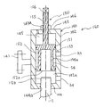
次にこの発明の参考例8を図14により説明するが、参考例7と同一図面符号はその名称も機能も同一である。参考例8が参考例7と異なる点は、半開維持手段が開度調整用ポジショナ装置660ではなくてスイッチSW2と電磁弁651及びオリフィス655に代わったことと、再開弁手段が充水感応用パイロット弁631ではなくて圧力スイッチPSと電磁弁653に代わったことである。
【0158】
まず、常時閉の起動弁650と常時開の開度維持電磁弁651とを設けた導圧管640が一次側配管20と加圧室13とに接続され、オリフィス655を設けた導圧分管641が開度維持電磁弁651と並列に導圧管640に接続されている。開閉弁本体100の上面から突出しているステム112の上端112bの軌道内に常時オフの跳ね返りスイッチSW2のレバー先端SL2があり、上端112bの上昇によってレバー先端SL2が回動する。SW2は、開閉弁本体100に取り付けられた高さ位置調整可能にスライド固定できる支持体SL2に搭載されている。
【0159】
上端112bの上昇通過によりレバー先端SL2は回動しステム112とは摺動状態でオンとなり、上端112bの下降離間によりレバー先端SL2は跳ね戻りオフとなる。このスイッチSW2の信号線L2は常時開の開度維持電磁弁651につながれている。開度維持電磁弁651はスイッチSW2がオンの時は閉弁し、オフの時は開弁する。
【0160】
支持体SL2は、開閉弁本体100等に固定する取付部とネジ孔を形成した太パイプを取付部の上方に設けた下部品と、スイッチSW1を取り付ける搭載部とその下方に設けた細パイプからなる上部品との、二つの部品からなり、太パイプに細パイプを挿入しネジ孔に止めネジを螺入して、任意の高さで固定するようにしたものである。
【0161】
加圧室13はオリフィス654と常時開の再開弁電磁弁653を直列に設けた排水管642に接続されて大気に開放されている。この再開弁電磁弁653は、二次側に取り付けられた圧力スイッチPSとが信号線L3でつながれている。
【0162】
なお、この圧力スイッチPSとこの信号線L3とは充水検知手段を、SW2と信号線L2と開度維持電磁弁651とは半開維持手段を、再開弁電磁弁653は再開弁手段を、支持体ST2は維持開度設定手段をそれぞれ構成している。
【0163】
次に上記参考例8の作動を説明する。図14は起動弁650が開かれた直後の状態を示している。 図示しない火災感知器からの火災信号を受けた図示しない制御装置により開弁信号が送られ常時は閉の起動弁650が開かれると、一次側配管20の消火水は導圧管640を通り、起動弁650、開度維持電磁弁651およびオリフィス655を通過して加圧室13に入る。
【0164】
この導圧管640からの給水流量は、脱気孔15からの排水流量と排水管642からの排水流量の合計よりも大きく設定するので、制御ピストン11が押し上げられ、制御ピストン11とステム112を介して連結された弁主体5(図3参照)が開き始めると一次側配管20内の消火水は二次側配管30に流れ込む。
【0165】
すると実施形態1と同様な動作をして、弁主体5が開き始めると一次側配管20の消火水は二次側配管30に流れ込み、ステム112が上昇してステム上端112bがスイッチSW2のレバー先端SL2をオン側に倒す。すると、開度維持電磁弁651が閉じられ加圧室13への給水はオリフィス655からだけとなる。このとき加圧室13からの消火水は排水管642と脱気孔15を通して給水流量よりも大きな流量で排水されるので、ステム112は下降しだしてステム上端112bがスイッチSW2のレバー先端SL2から離れてオフとなる。すると、開度維持電磁弁651が開き、また給水流量の方が大きくなるので、ステム112は上昇し出す。
【0166】
このようなことが繰り返されレバー先端SL2の回動範囲でステム112が上下動を繰り返し、それに伴って、開閉弁本体100は、上下動しながら半開状態を維持する。
【0167】
このとき、開度維持電磁弁651とオリフィス655を合流した給水流量と、脱気孔15からと排水管642からとの合計の排水流量は、平均的にならすと等しくなる。
【0168】
そのあと半開維持状態で二次側配管30に給水されて、この二次側配管圧が圧力スイッチPSの設定値を越えると信号線L3を介して、今まで排水していた再開弁電磁弁653を閉弁させる。すると、導圧管640から加圧室13からの排水流量は脱気孔15からだけとなり、オリフィス655の給水流量と開度維持電磁弁651の給水流量により排水流量にうち勝って、制御ピストン11は再び全開方向に動き始める。
【0169】
弁主体5が更に上昇するのに伴い、ステム上端112bが上昇しスイッチSW2をオンさせるので、開度維持電磁弁651が閉じられ、加圧室13への流路はオリフィス655だけに絞られる。この時の加圧室13への給水流量は、脱気孔15からの排水流量よりも大きく設定するので、制御ピストン11は上昇を続け主体5は開弁方向へ動く。その後は前述と同様な作動をして全開までに至る。
【0170】
弁主体5を閉めたい場合は図示しない制御装置を操作する。すると閉弁信号が送られ起動弁650が閉じられ、一次側配管20からの加圧室13への給水が停止され、加圧室13の圧力はなくなり弁主体5は閉弁に至る。
【0171】
一方、弁主体5とともにステム112が下がり、ステム上端112bが跳ね返りスイッチSW2のレバー先端SL2から離れてオフとなり、開度維持電磁弁651を開に戻す。また、弁主体5の閉弁により二次側配管30の二次圧が減圧し、この二次圧が圧力スイッチPSの設定値より低くなると再開弁電磁弁653が開き元の状態に戻る。
【0172】
この参考例は上記のように構成したので、開閉弁本体100が特製品である必要がなく、既存の開閉弁を取り替えることも、加工することもなくそのまま利用できる。 また、上記のように、弁本体5を、跳ね返りスイッチSW2のステム上端112bに対する取付け高さで、適切な半開維持状態に設定でき、二次圧が所定圧以上になると、弁本体5が全開となるので、ウオーターハンマ現象は防止でき、二次側への充水も遅れることも少なく達成できる。
【0173】
ところで上記までの参考例または実施形態は全て、加圧することにより開くタイプの弁、所謂加圧開の弁であった。しかしこの発明は、減圧することにより開く減圧開のタイプの弁にも適応される。
【0174】
参考例9を図15および図4を用いて説明するが、参考例2と同一図面符号はその名称も機能も同一である。
【0175】
まず、導圧管720が一次側配管20と加圧室13とに接続され、減圧室14には、下流に向かって常時閉の起動弁730と常時閉の充水感応用パイロット弁731とが順に接続されて先端が大気に開放する排水管721が接続されている。この排水管721には起動弁730と充水感応用パイロット弁731との間から逃がし配管722が分岐しており、その配管722の他端は常時開の開度調整用ポジショナ装置160の加圧孔h4に接続されている。
【0176】
この開度調整用ポジショナ装置160の連通孔h3からはオリフィス732を設け大気に開放する第二逃がし配管723が接続されている。また常時閉の充水感応用パイロット弁731の感圧部には二次側配管30と感圧管724を介して接続されている。
【0177】
なお、感圧管724と充水感応用パイロット弁731は充水検知手段を、開度調整用ポジショナ装置160は半開維持手段を、充水感応用パイロット弁731は再開弁手段を、それぞれ構成している。参考例9の作動を図15および図3と図4を使って説明する。図15および図4は、起動弁730が開かれた直後の状態を示している。平時、待機状態において一次側配管20に常時高圧の一次圧たとえば10kg/cm2がかかっているので加圧室13および脱気孔15で連通する減圧室14までこの一次圧がかかっている状態である。この状態で火災等が発生したとき、図示しない火災感知器からの火災信号を受けた図示しない制御装置により開弁信号が送られ、常時は閉の起動弁730が開かれる。
【0178】
当初弁主体5は全閉でありステム112が最下端に位置しているので、図4に示すように連通孔h3と加圧孔h4とは連通しているため、減圧室14は大気に連通し、減圧室14の空気が急速に抜けていく。すると、一次側配管20は減圧室14等を介して大気との間で圧力勾配を生ずるので、一次側配管20の消火水は、導圧管720を通り加圧室13、脱気孔15、減圧室14、排水管721、起動弁730、逃がし配管722、加圧孔h4、ステム室145a、シリンダ室152、シリンダ孔154a、空間部153,連通孔h3、第二逃がし配管723、オリフィス732、大気、という流路を通って脱気の後、排水される。
【0179】
このとき、導圧管720の流過面積および排水管721以降の流過面積のいずれもが、脱気孔15の流過面積より十分に大きいので、加圧室13は殆ど一次圧に等しく、減圧室14は大気圧に近いかなり低い圧となる。すなわち加圧室13と減圧室14との圧力差が大きく発生し、弁主体5の上にかかる一次圧による下方への力よりも制御ピストン11の下からの力の方が大きく、その結果弁主体5を押し上げる。
【0180】
すると、ステム112の上端112bがシリンダ開口部152aに挿入されて排水路を遮断するので減圧室14は脱気孔15を通じて急激に加圧室13の圧力に近づく。すると加圧室13と減圧室14との差圧が小さくなるので上方への力が下方への力よりも小さくなり、弁主体5は下がり始める。すると上端112bがシリンダ開口部152aから抜かれるので排水路が開き、再び加圧室13と減圧室14との圧力差が大きくなる。
【0181】
このようなことを繰り返すため、弁主体5は開度調整用ポジショナ150のシリンダ開口部152aとステム112との隙間、つまり加圧室13の圧力による上への力と、減圧室14の圧力による力及び弁本体5にかかる下への力との和が均衡したところで、半開状態で開弁動作が一旦停止する。
【0182】
半開維持状態で二次側配管30に給水されると、次第に二次側配管30の圧力、すなわち二次圧が増して行き、この二次圧が予め設定しておいた充水感応用パイロット弁731の設定値を越えると、二次圧を感圧管724で伝えるのでこのパイロット弁731が開弁する。すると、脱気孔15よりも充分に大きな流過面積でパイロット弁731が開かれるので、減圧室14は十分に低圧になり、弁主体5は全開までに至る。尚、上記オリフィス732は逃がし配管722又は導圧管720に設けてもよい。
【0183】
弁主体5を閉めたい場合は、図示しない制御装置が操作されて閉弁信号が送られ起動弁730を閉じると、流路が絶たれ減圧室14の圧力は加圧室13と等しくなり、差圧が無いので開弁方向の力がなくなり、一次圧などが弁主体5を閉弁方向に押して弁主体5は閉弁に至る。
【0184】
一方、弁主体5とともにステム112が下がり、ステム上端112bがシリンダ開口部152aから離れて、二つの逃がし配管722,723がシリンダ室152を介して連通状態になって、開度調整用ポジショナ装置160が復旧する。また、弁主体5の閉弁により二次側配管30の二次圧が減圧するので、この二次圧が充水感応用パイロット弁731の設定値より低くなると充水感応用パイロット弁731が閉じられて、この充水感応用パイロット弁731も元の状態に戻る。
【0185】
上記参考例9は、半開維持手段として参考例2の開度調整用ポジショナ装置160を用いたが、その代わりに参考例3の水撃防止用パイロット弁340あるいは参考例4の水撃防止用パイロット弁440を用いてもよい。また、再開弁手段として排水管721に設けた充水感応用パイロット弁731を用いたが、その代わりに充水感応用パイロット弁および水撃防止用パイロット弁340を用いてもよい。
【0186】
すなわち、水撃防止用パイロット弁340を用いる場合においては、逃がし配管722を加圧孔h4に接続する代わりに連通孔h7に接続し、第二逃がし配管723を連通孔h3に接続する代わりに弁室孔h8に接続し、かつステム112にインジケータ250を装着する。このようにすると、ステム112の動きに連動して減圧室14からの排水を減少制御し主弁体5を半開維持状態にする半開維持手段としての水撃防止用パイロット弁340を備えることができる。
【0187】
また、一方、充水感応用パイロット弁731は図15の通りに排水管721の末尾につけるようにしてもよいが、図7のように、二次側配管30に接続された感圧管を充水感応用パイロット弁を介して感圧孔h9に接続するようにしてもよい。この場合、充水感応用パイロット弁は常時閉で、その感圧部には充水感応用パイロット弁の一次側の圧力をとるようにする。また、図15における充水感応用パイロット弁731と分岐以降の下流の排水管721は除かれ、その結果排水管721と逃がし配管722とは直列に接続される形となる。
【0188】
このようにすると、充水感応用パイロット弁の充水検知によって、減圧室14からの排水を半開維持状態よりも増大制御した再開弁手段としての水撃防止用パイロット弁340を備えることができる。
【0189】
この発明は上記参考例に限らず、あらゆる減圧開タイプの開閉弁に対応する。
【0190】
この参考例は上記のように構成したので、開閉弁本体100が特製品である必要がなく、既存の開閉弁を取り替えることも、加工することもなくそのまま利用できる。また上記のように、弁本体5を開度調整用ポジショナ150で適切な半開維持状態に設定でき、二次圧が所定圧以上になると、弁本体5が全開となるので、ウオーターハンマ現象は防止でき、二次側への充水も遅れることも少なく達成できる。この発明は、上記参考例1乃至9および実施形態1に記載したことに限らず、各構成をそれぞれ互いに組み合わせるようにしてもよい。また、加圧室13の一次側に設けられた起動弁は減圧室14の二次側に設けてもよく、逆に減圧室14の二次側に設けられた起動弁を加圧室13の一次側に設けるようにしてもよい。また、以下に示すようにしてもよい。
【0191】
充水検知手段において、感圧管は二次側配管の直後に接続してもよいが、二次側配管の先端(ノズル側)の近くに接続してもよい。充水検知を圧力として検知するのではなく、消火水の流動を検知するようにしてもよい。例えば、二次側配管の先端側や中間距離あたりの配管内の上部位置に流動検知板を備えるようにしてもよい。このようにすると、起動初期には消火水は二次側配管の下部を流れるので検知せず、充水すると上部の検知板を流水の力で動かして検知される。
【0192】
また、同様に二次側配管内上部に一対の電極を備え、充水したときに電極間に消火水を介して通電されることで、充水を検知するようにしてもよい。また、熱電対を二次側配管内上部に備え、管内空気温度から急に消火水温度に変わる温度の変化を捕らえて、充水を検知するようにしてもよい。
【0193】
半開維持手段において、上記参考例ではステムとの連動関係を持たせるのに、ステムを半開維持手段に直接関わるようにしたが、ステムの変位を伝達する手段を用いて間接的にステムとの連動関係を持たせるようにしてもよい。例えば、ステムの変位の伝達手段として、ステムにリンク機構やワイヤーやバネを連結させたりしてもよい。また、ステム先端に磁石を取り付けて位置を検出する磁気スイッチや、ステムの軌道内に光路をおいてステムによる光遮断でステムの位置を検出する手段など、いかなる位置検出手段を用いてもよい。
【0194】
また、上記参考例または実施形態に記載された半開維持手段では特製の弁装置を用いるようにしたが、一般の弁を用いるようにしてもよい。例えば、実施形態1の水撃防止用パイロット弁240の代わりに、一般のボール弁またはグローブ弁を用い、開弁のハンドル部をレバー状の構造にして、ステムが上昇したときにボール弁等が開くように、レバーとステムをリンクするようにしてもよい。この場合、第二逃がし配管223に半開開度を維持するためのオリフィスを取り付けるようにする。
【0195】
また、参考例6や参考例8(図12、図14参照)において、半開維持手段は電磁弁を用いるようにしたが、その代わりに電動ニードル弁を用いてもよい。
【0196】
参考例6の場合(図12参照)、SW1がオンになったとき電動弁の減速機付きのモーターが開弁方向に回りニードル弁が緩慢に開いていき、ステムが下がってSW1がオフになったときモーターは閉弁方向に回りニードル弁が緩慢に閉じていくようにすると、電磁弁の時のように激しく開閉を繰り返さなくてすむ。
【0197】
上記参考例および実施形態では再開弁手段として、二次側配管圧力によって動作するようにしたパイロット弁を用いていたが、これに限らず電磁弁や他のいかなる手段も用いることができる。
【0198】
上記参考例および実施形態では維持開度設定手段は、ステムに弁体機能を持たせた時の弁連通口側の位置を調整可能にしたものや、ステムへの取付具の高さや半開維持手段の支持体の高さを調節可能にしたものであったが、ステムの変位の伝達手段としてステムと半開維持手段の間にリンク機構などを介在させた場合において、そのリンク機構に位置調整をできるようなものにしてもよい。
【0199】
【発明の効果】
以上のような構成なので、起動弁を開けることにより弁主体が上昇し、設定の開度で半開維持状態となる。このとき高圧の消火水は一次側配管から二次側配管に勢いよく流れ込むが、二次側配管に充水されるまで半開状態が維持される。従って、二次側配管の流水は緩和されてウオーターハンマ現象による異常な衝撃発生を回避できる消防用設備の開閉弁装置が得られるという効果がある。
【0200】
また、半開維持手段に、所望の開度で弁主体が半開維持するようにした維持開度設定手段を設けたので、個々の設備配管条件やポンプ設備容量に応ずることができる、現場などでも調整可能なウォーターハンマ対応構造を備え、ウォーターハンマおよび初期消火に最適な条件が得られる開閉弁装置が得られるという効果がある。
【0201】
【図面の簡単な説明】
【図1】本発明の参考例1を示す縦断面図である。
【図2】図1の要部拡大図である。
【図3】本発明の参考例2を示す系統図である。
【図4】図3の開度調整ポジショナ装置の縦断面図である。
【図5】本発明の実施形態1を示す系統図である。
【図6】図5の水撃防止用パイロット弁の縦断面図である。
【図7】本発明の参考例3を示す系統図である。
【図8】図7の要部拡大断面図である。
【図9】本発明の参考例4を示す系統図である。
【図10】図9の要部拡大断面図である。
【図11】本発明の参考例5を示す系統図である。
【図12】本発明の参考例6を示す系統図である。
【図13】本発明の参考例7を示す系統図である。
【図14】本発明の参考例8を示す系統図である。
【図15】本発明の参考例9を示す系統図である。
【符号の説明】
1,100開閉弁本体、2一次流路、3二次流路、4連通口、5弁主体、10ピストン室、11制御ピストン、12,112ステム、13加圧室、14減圧室、15脱気孔、17排水弁、20一次側配管、23,123,224,322,422,525,545感圧管、25遠隔起動用電磁弁、130,230,330,530,630起動弁、26,120,121,220,221,320,321,520,620,621,640導圧管、26a、122,521,541,641導圧分管、30二次側配管、33,132,232,332,533,553,631充水感応用パイロット弁、42突出部、50,150開度調整用ポジショナ、160,660開度調整用ポジショナ装置、52a,152a,652aシリンダ開口部、55,155長ネジ部、56,156把持部、240,340,440水撃防止用パイロット弁、248ロッド、250インジケータ、253止めネジ、ST,ST1,ST2支持体、SW1,SW2跳ね返りスイッチ、552開度維持電磁弁、653再開弁電磁弁
--------------------------------------------------------------------------------[0001]
BACKGROUND OF THE INVENTION
The present invention relates to an on-off valve device for a fire-fighting facility such as a plant disaster prevention facility, and more particularly to an on-off valve device installed in a long pipeline, a large-diameter water curtain facility, a water cannon, or the like.
[0002]
[Prior art]
A conventional on-off valve device for plant disaster prevention equipment includes a valve main body that connects a primary side pipe and a secondary side pipe, a valve main body that opens and closes a communication port of the valve main body, a lower side of the valve main body, and a secondary body. A piston chamber opposed via a flow path, a control piston disposed in the piston chamber and having a larger pressure receiving area than the valve main body, a stem connecting the control piston and the valve main body, and a lower portion of the control piston And a pressure chamber of a piston chamber that moves the valve main body in the valve opening direction by being pressurized, and a pressure guiding tube with a start valve that makes the pressure chamber communicate with the primary side pipe. .
[0003]
In the event of a fire, when the start valve is opened and the extinguishing water in the primary pipe is supplied to the pressurizing chamber, the control piston moves upward, that is, in the direction of the valve main body due to the water pressure in the pressurizing chamber. The main body also moves upward, and the valve main body opens. Since the valve main communication port is opened, the fire extinguishing water in the primary side pipe flows into the secondary side pipe and is discharged from the water cannon through the pipe line.
[0004]
[Problems to be solved by the invention]
In the conventional technology, when the start valve is opened and extinguishing water is supplied to the pressurizing chamber, the valve main body suddenly leaves the valve seat and reaches the full opening at once, so the high-pressure extinguishing water in the primary side pipe is It will be pumped at high speed in the secondary side piping which is not done. And when the flow of fire-extinguishing water is squeezed rapidly at the nozzle opening when radiating from the water cannon, the flow speed of the high-pressure fire-extinguishing water is drastically dropped, so an extremely large impact is applied to the nozzle and piping equipment. The so-called water hammer phenomenon occurs. In view of the above circumstances, an object of the present invention is to obtain an on-off valve device for a fire fighting facility that prevents the occurrence of an excessive water hammer phenomenon.
[0005]
The occurrence of water hammer phenomenon varies depending on the equipment conditions of the secondary side pipe, but in general, water hammer can be avoided by gradually increasing the flow rate at the time of valve opening. However, initial fire extinguishing is important in the event of a fire, and there is also a demand to discharge water as soon as possible. The structure of the on / off valve device for preventing water hammer that compromises both of these conditions depends on the shape equipment conditions and pump equipment capacity of the entire pipeline, and cannot be handled by a uniform fixed structure. A second object of the present invention is to provide an on-off valve device for a fire-fighting facility that has a water hammer-compatible structure that can be adjusted at the site and that provides optimum conditions for preventing water hammer and initial fire extinguishing.
[0006]
[Means for Solving the Problems]
The present invention relates to a valve main body that connects a primary side pipe and a secondary side pipe, a valve main body that opens and closes a communication port of the valve main body, a piston chamber that faces the valve main body through a flow path, and the piston A control piston disposed in the chamber and having a pressure receiving area larger than that of the valve main body, a stem connecting the control piston and the valve main body, an indicator attached to an end of the stem and having a tapered portion, a rod head A pilot valve for preventing water hammer comprising a portion, a pressurizing chamber of the piston chamber for moving the valve main body in the valve opening direction via the stem by being pressurized adjacent to the control piston, and the pressurizing chamber And an on-off valve device comprising: a pressure guiding pipe that communicates with the primary side pipe; and a water filling detecting means that detects filling of the secondary side pipe, wherein the pressure guiding pipe communicates with the water hammer prevention pilot valve. Before When the fire extinguishing water of the primary side pipe flows into the secondary side pipe, the water hammer prevention pilot valve depends on the position where the taper part of the indicator and the rod head of the water hammer prevention pilot valve come into contact with each other. Opens or closes the valve, maintains the valve main body at a predetermined opening degree, and controls the water supply to the pressurizing chamber by closing the water filling application pilot valve by detecting the water filling of the detecting means. The objective is achieved by moving the valve main body in the fully open direction.
[0007]
DETAILED DESCRIPTION OF THE INVENTION
Reference Example 1 of the present invention will be described with reference to FIGS. The on-off valve body 1 is connected between the primary side pipe 20 and the secondary side pipe 30, and the casing 40 of the on-off valve body 1 includes a primary flow path 2 through which the primary side pipe 20 communicates, and a secondary side pipe. The secondary flow path 3 with which 30 communicates is comprised, and the piston chamber 10 adjacent to this secondary flow path 3, for example located in the downward direction, is comprised.
[0008]
The on-off valve body 1 is formed with a communication port 4 that allows the primary flow path 2 and the secondary flow path 3 to communicate with each other. A valve seat 6 on which the valve main body 5 is seated is formed at the upper edge of the communication port 4. A spring S mounted between the valve main body 5 and the canopy 44 of the casing 40 facing the primary flow path 2 is pressed against the upper surface of the valve main body 5, and the lower flow rate is gradually increased on the lower surface. A tapered skirt 7 is provided.
[0009]
The piston chamber 10 facing the valve main body 5 via the secondary flow path 3 is connected to the valve main body 5 via the stem 12 and is fitted with a control piston 11 having a larger pressure receiving area than the valve main body 5. It is worn. The piston chamber 10 is partitioned by this control piston 11 into a pressurizing chamber 13 on the lower side and a decompression chamber 14 on the upper side, and both the chambers 13 and 14 are communicated with each other through a small diameter deaeration hole 15 formed in the control piston 11. A drain pipe 16 with a drain valve 17 having a larger flow area than the deaeration hole 15 is connected to a wall portion of the decompression chamber 14 which is a part of the casing 40. The drain valve 17 is normally open.
[0010]
The bottom of the pressurizing chamber 13 is formed by a piston chamber lid 41 that closes the bottom opening of the casing 40. A bottomed cylindrical projecting portion 42 that receives the lower end of the stem 12 projecting downward from the control piston 11 and fits the body portion 51 of the opening adjustment positioner 50 is formed on the lower surface of the center of the lid 41. Has been.
[0011]
The opening adjusting positioner 50 has a cylindrical body 51 with a bottom and a female screw hole 42b that protrudes coaxially with the body 51 from the lower part of the body 51 and is formed at the bottom of the protrusion 42 of the lid 41. It is comprised with the long screw part 55 screwed. A spanner gripping portion 56 is formed at the lower end of the long screw portion 55, and a lock nut 43 is screwed on the long screw portion 55 on the outside of the protruding portion 42 of the lid body 41.
[0012]
A small diameter portion 54 slightly smaller than the diameter of the trunk portion 51 is formed at an intermediate position of the trunk portion 51 of the opening adjustment positioner 50, and when the projection portion 42 is fitted, a space portion 53 is formed around the small diameter portion 54. It is formed. On the other hand, a cylinder chamber 52 is formed inside the body portion 51, and a cylinder hole 54 a communicating the cylinder chamber 52 and the space portion 54 is formed in the small diameter portion 54.
[0013]
The lower end 12a of the stem 12 can be inserted into the upper end opening of the cylinder chamber 52, and when the lower end 12a formed so that the O-ring can be attached as the valve main body 5 opens, the cylinder chamber passes. A cylinder opening 52 a having a smaller diameter than the cylinder chamber 52 is formed so that the pressure chamber 52 and the pressurizing chamber 13 do not communicate with each other. Above the lower end portion 12a, a stem neck portion 12b having a smaller diameter than the cylinder opening 52a and a sufficient length is formed by machining. Thereby, the opening degree adjusting positioner 50 and the protrusion 42 constitute a half-opening maintaining means.
[0014]
A primary pressure hole h <b> 1 that communicates with the space portion 53 is formed on the side of the protruding portion 42, and a pressurizing chamber hole h <b> 2 that communicates with the pressurizing chamber 13 is formed on the lid body 41. An upper end 12c of the stem 12 protrudes from the upper surface of the valve main body 5 and penetrates the canopy 44 through a packing to indicate the opening of the valve as an indicator.
[0015]
The primary pressure hole h1 is connected to the primary side pipe 20 via a pressure guiding pipe 26 with a remote starting electromagnetic valve 25. In order to the primary pressure hole h <b> 1, a maintenance valve 28, a strainer 29, a remote start solenoid valve 25, a field manual start valve 32 arranged in parallel with the solenoid valve 25, a secondary pressure are provided in the pressure guide pipe 26 in order from the primary side pipe 20. A setting pilot valve 34 and an orifice 31 are connected. Further, a pressure guiding branch pipe 26a branched between the orifice 31 and the primary pressure hole h1 is connected to the pressurizing chamber hole h2 via a water filling application pilot valve 33 as a restart valve means.
[0016]
The remote start solenoid valve 25, the on-site manual start valve 32, and the water filling application pilot valve 33 are normally closed. The maintenance valve 28 and the secondary pressure setting pilot valve 34 are normally open. The secondary pipe 30 and the pressure sensing part of the water filling application pilot valve 33 are connected via a pressure sensing pipe 23. The filling feeling application pilot valve 33 and the pressure sensing pipe 23 constitute a filling detection means. The secondary pipe 30 and the pressure sensing part of the secondary pressure setting pilot valve 34 are connected via a pressure sensing pipe 23 and a pressure sensing branch pipe 23 a branched from the pressure sensing pipe 23.
[0017]
The secondary pressure setting pilot valve 34 is a valve that is normally open, and is closed when the pressure sent to the pressure sensing portion of the pilot valve 34 reaches a set value. The water filling application pilot valve 33 is normally closed. In the valve state, the valve is opened when the pressure sent to the pressure sensing unit reaches a set value. These pilot valves are general ones, but the structures of the secondary pressure setting pilot valve 34 and the water filling application pilot valve 33 are the same as those of the fully open auxiliary pilot valve 30 described in Japanese Patent Application No. 9-335846, for example. Each structure of the pressure pilot valve 25 can be used. The same applies to pilot valves used in the following embodiments.
[0018]
Next, the operation of the first reference example will be described. First, the case of opening the on-off valve device will be described in detail. In response to a fire signal from a fire detector (not shown), a control device (not shown) sends a valve opening signal to the electromagnetic valve 25 for remote activation. When the remote start solenoid valve 25 is opened, the fire extinguishing water in the primary side pipe 20 passes through the pressure guiding pipe 26, passes through the remote start solenoid valve 25, the secondary pressure setting pilot valve 34, and the orifice 31, and then enters the protrusion 42. It enters from the primary pressure hole h1, passes through the space 53, the cylinder hole 54a, the cylinder chamber 52, and the cylinder opening 52a in order, and is pressurized and supplied to the pressurizing chamber 13. 1 and 2 show a state immediately after the start valve 25 is opened.
[0019]
Since the valve main body 5 is initially closed, the lower end 12a of the stem 12 is in the cylinder chamber 52 of the opening adjustment positioner 50, and the stem neck 12b is located at the cylinder opening 52a. For this reason, the cylinder chamber 52 and the pressurizing chamber 13 are in communication.
[0020]
The fire-extinguishing water supplied to the pressurizing chamber 13 discharges the air in the pressurizing chamber 13 from the deaeration hole 15 to the decompression chamber 14, and after the pressurization chamber 13 is filled, the fire-extinguishing water passes through the deaeration hole 15. After flowing into the decompression chamber 14 and filling the decompression chamber 14, the fire extinguishing water is drained from the drain pipe 16. At this time, when the pressurizing chamber 13 is filled, the control piston 11 having a pressure receiving area larger than the pressure receiving area of the valve main body 5 receives the primary pressure of the extinguishing water on the lower surface, and the primary of the extinguishing water applied to the valve main body 5. The control piston 11 is pushed up against the pressure, the pressure contact force of the spring S, the friction force, and the weight of the valve main body 5 and the like. As a result, the valve main body 5 is pushed up via the stem 12.
[0021]
When the valve main body 5 starts to open, the fire-extinguishing water in the primary flow path 2 flows into the secondary side pipe 30 via the secondary flow path 3. When the extinguishing water is further supplied to the pressurizing chamber 13 and the control piston 11 is raised, the lower end 12a of the stem 12 rises and is positioned at the cylinder opening 52a. The opening 52a is sealed, and the cylinder chamber 52 and the pressurizing chamber 13 are disconnected from each other.
[0022]
Then, the fire extinguishing water is not supplied to the pressurizing chamber 13, and the pressure in the pressurizing chamber 13 escapes from the deaeration hole 15 and the drain pipe 16. Therefore, the valve main body is driven by the primary pressure applied to the valve main body 5 and the downward force of the spring S or the like. 5 comes to move in the closing direction. Then, the lower end 12a moves away from the cylinder opening 52a, the supply of the fire-extinguishing water from the cylinder chamber 52 to the pressurizing chamber 13 is started, and the valve main body 5 moves in the valve opening direction after starting to rise again.
[0023]
Since this is repeated, the valve opening operation is temporarily stopped while the valve main body 5 is in the half-open state at the height position of the cylinder opening 52a adjusted by the opening adjustment positioner 50. The half-open state is a state in which the valve main body 5 is opened at an opening degree that does not cause excessive water hammer when the valve main body 5 does not reach the full opening and that can secure a flow rate to the secondary side pipe 30 to some extent. Point. The opening degree varies depending on the on-site equipment conditions such as the pump equipment capacity and the secondary side piping conditions. On the other hand, the opening degree adjusting positioner 50 can adjust the opening degree to an optimum degree.
[0024]
Thus, when the secondary side pipe 30 is filled with water in the half-open maintained state, the pressure on the secondary side gradually increases, and this secondary pressure is set in the preset water feeling application pilot valve 33. When a set value is exceeded, for example, 2 kilograms per square centimeter (hereinafter referred to as kg / cm 2), it is considered that the water has been filled. At this time, the pressure of the secondary side pipe is transmitted through the pressure sensing pipe 23, the pilot valve 33 is opened, and water is supplied to the pressurizing chamber 13 through the pressure branching pipe 26a through the pressurizing chamber hole h2. . Then, the valve main body 5 starts to move again in the valve opening direction (upward).
[0025]
When the opening of the valve main body 5 increases and the secondary pressure increases and the secondary pressure exceeds the set pressure of the pilot valve 34 for setting the secondary pressure, for example, 5 kg / cm 2, this pressure is changed to the pressure sensing tube 23 and the pressure sensitive pressure. Since it is transmitted to the sensitive part of the pilot valve 34 for setting the secondary pressure via the branch pipe 23a, the pilot valve 34 is throttled and water supply to the pressurizing chamber 13 is reduced. When the water supply flow rate becomes smaller than the drainage flow rate from the deaeration hole 15, the control piston 11 and the valve main body 5 stop rising in the fully open direction and turn downward. If it becomes like this, since the flow volume of the on-off valve main body 1 will reduce, secondary pressure will fall.
[0026]
On the other hand, if the secondary pressure is lower than the set pressure 5 kg / cm 2, this pressure is transmitted through the pressure sensing pipe 23 and the like, the pilot valve 34 opens, and the feed water flow rate to the pressurizing chamber 13 is reduced from the deaeration hole 15. The control piston 11 and the valve main body 5 stop rising in the valve closing direction and start to rise, the flow rate of the on-off valve body 1 increases, and the secondary pressure starts to rise. Eventually, the secondary pressure remains around the set pressure. In this way, the secondary pressure is adjusted by the secondary pressure setting pilot valve 34.
[0027]
By the way, in a plant disaster prevention facility having a fire-fighting facility such as the above-described on-off valve device, there is a case where it is desired to change the opening degree of the half-open maintenance state, that is, the temporary stop state at the site, etc. according to the pipeline condition or the capacity of the pump facility. .
[0028]
In that case, the lock nut 43 of the positioner 50 for adjusting the opening degree is loosened and the grip 56 is rotated with a spanner or the like to adjust the height position of the cylinder opening 52a. That is, when it is desired to make the temporary stop opening larger, the gripping portion 56 is turned to the right, and the opening adjustment positioner 50 is raised and set high by screwing into the female screw hole 42b. If desired, the grip 56 is turned counterclockwise to lower the opening adjustment positioner 50 and set it low, and the lock nut 43 is tightened when determined. The holding portion 56, the long screw portion 55, and the female screw hole 42b constitute a maintenance opening setting means.
[0029]
Next, a case where the on-off valve is closed will be described. A control device (not shown) is operated, and this control device sends a valve closing signal to the electromagnetic valve 25 for remote activation. When the remote start solenoid valve 25 is closed, the fire extinguishing water in the primary side pipe 20 stops supplying water to the cylinder chamber 52 and the pressurizing chamber 13. Then, since the pressure in the pressurizing chamber becomes substantially equal to the drainage external pressure, that is, the atmospheric pressure, the valve main body 5 is pushed down by the differential pressure between the primary pressure and the secondary pressure of the valve main body 5 and the pressure contact force of the spring S. The fire extinguishing water in the pressurizing chamber 13 moves to the decompression chamber 14 through the deaeration hole 15, and the valve main body 5 is seated on the valve seat 6 and is fully closed.
[0030]
Further, since the secondary pressure of the secondary side pipe 30 is reduced by closing the valve main body 5, when this secondary pressure becomes lower than the set value of the filling feeling applied pilot valve 33, the filling feeling applied pilot valve 33 is closed. As a result, the water filling application pilot valve 33 also returns to its original state.
[0031]
As described above, the valve body 5 can be set to an appropriate half-open maintained state by the opening adjustment positioner 21, and when the secondary pressure exceeds a predetermined pressure, the valve body is fully opened, so that the water hammer phenomenon can be prevented. Recharge of the secondary side can be achieved with little delay.
[0032]
Next, Reference Example 2 of the present invention will be described with reference to FIGS. 3 and 4. The same reference numerals as in Reference Example 1 have the same names and functions.
[0033]
The on-off valve body 100 is different from the on-off valve body 1 of the reference example 1 in that the lower end of the stem 12 of the on-off valve body 1 protrudes downward from the control piston 11 and is machined. Whereas the protruding portion 42 is formed on the piston chamber lid body 41, the lower end of the stem 112 does not protrude greatly downward from the control piston 11 and the stem neck portion 12b of the first reference example etc. In other words, the piston chamber lid body 141 is not formed with a protrusion, that is, the opening degree adjusting positioner 50 is not incorporated.
[0034]
In Reference Example 2, the opening adjustment positioner device 160 as a half-opening maintaining means is a separate body, and the housing 140 of the opening adjustment positioner device 160 is attached to the canopy 44 of the on-off valve body 100. A support part 141 provided in the housing 140 is fixed to the support ST. The casing 140 has a cylindrical shape with a bottom and a stem hole 144a opened in the lower base 144, and a stem 112 penetrating and projecting from the canopy 44 is inserted through a watertight structure such as packing.
[0035]
The cylindrical chamber 145 formed in a cylindrical shape in the housing 140 is fitted with a bottomed cylindrical body 151 of an opening adjustment positioner 150, and a cylinder formed inside the body 151. A cylinder opening 152 a at the lower end of the chamber 152 is provided so that the upper end 112 b of the stem 112 can be inserted. A long screw portion 155 having a grip portion 156 formed at the upper end thereof is protruded from the upper bottom of the opening adjustment positioner 150, and the long screw portion 155 is a female screw hole 143 a formed in the upper bottom 143 of the housing 140. Screwed into.
[0036]
The stem 112, the cylinder chamber 152, the body portion 151, the cylindrical chamber 145, the long screw portion 155, and the female screw hole 143a are all located coaxially as shown in FIG. A lock nut 146 is screwed on the long screw portion 155 outside the housing 140.
[0037]
There is a small-diameter portion 154 formed slightly smaller than the outer diameters of the upper and lower ends at the central portion of the trunk portion 151, and when it is fitted in the cylindrical chamber 145, the trunk portion is located between the cylindrical chamber 145 and the wall surface. A space portion 153 is formed on the entire circumference of the central side surface of 151. The small diameter portion 154 is provided with a cylinder hole 154 a that communicates the space portion 153 and the cylinder chamber 152, and the side portion 142 of the housing 140 is provided with a communication hole h 3 that communicates with the space portion 153. Further, a cylindrical wall 145 facing the stem 112, that is, a pressure hole h4 communicating with the stem chamber 145a is provided on the lower wall surface of the housing 140.
[0038]
The communication hole h3 is connected to the primary side pipe 20 via the first pressure guiding pipe 120. An activation valve 130 and an orifice 131 are connected to the first pressure guiding pipe 120 in order from the primary side pipe 20 toward the communication hole h3. The pressurizing hole h <b> 4 is connected to the pressurizing chamber 13 of the on-off valve body 100 through the second pressure guiding pipe 121.
[0039]
Further, the second pressure guiding pipe 121 is branched into the pressure guiding pipe 122 on the way, and the pressure guiding pipe 122 is connected to the first pressure guiding pipe 120 via a water filling application pilot valve 132 as a restart valve means. . The secondary side pipe 30 is connected to the pressure sensing portion of the water filling application pilot valve 132 via a pressure sensing pipe 123. The water filling application pilot valve 132 is normally closed and opens when the pressure sensing unit exceeds a set pressure. In addition, the water filling application pilot valve 132 and the pressure sensing pipe 123 constitute a water filling detecting means.
[0040]
When it is desired to change the opening degree of the temporary stop, the lock nut 146 of the opening degree adjusting positioner 150 is loosened and the gripping part 156 is turned with a spanner or the like to adjust the height position of the cylinder opening 152a. After adjustment, the lock nut 146 is tightened and fixed. The holding portion 156, the long screw portion 155, and the female screw hole 143a constitute a maintenance opening setting means. The maintenance opening can also be set by changing the mounting height with the support ST.
[0041]
Next, the operation of Reference Example 2 will be described. 3 and 4 show a state immediately after the start valve 130 is opened. When a valve opening signal is sent by a control device (not shown) that receives a fire signal from a fire detector (not shown) and the normally closed start valve 130 is opened, the fire extinguishing water in the primary side pipe 20 passes through the first pressure guiding pipe 120. The passage start valve 130, the orifice 131, the communication hole h3, the space 153, the cylinder hole 154a, the cylinder chamber 152, the stem chamber 145a, the pressurizing hole h4, and the second pressure guiding pipe 121 are sequentially passed to the pressurizing chamber 13. Water is supplied.
[0042]
When water is supplied to the pressurizing chamber 13, the control piston 11 is pushed up, and when the valve main body 5 connected via the stem 112 connected to the control piston 11 starts to open, the fire-extinguishing water in the primary side pipe 20 is connected to the communication port. 4 flows into the secondary side pipe 30.
[0043]
As the extinguishing water is further supplied to the pressurizing chamber 13 and the control piston 11 is raised, when the stem upper end 112b rises and is positioned at the cylinder opening 152a, the stem upper end 112b seals the cylinder opening 152a, and the stem chamber The fire extinguishing water does not go to 145a, and the flow path to the pressurizing chamber 13 is cut off. As a result, the pressure in the pressurizing chamber 13 disappears, and the valve main body 5 starts to move in the closing direction. Then, the stem upper end 112b moves away from the cylinder opening 152a, water supply from the cylinder chamber 152 to the pressurizing chamber 13 is started, and the valve main body 5 starts to rise again and moves in the valve opening direction.
[0044]
Since this is repeated, the valve opening operation of the valve main body 5 is temporarily stopped in the half-open state due to the relationship between the height position of the cylinder opening 152a of the opening adjustment positioner 150 and the stem upper end 112b.
[0045]
When water is supplied to the secondary side pipe 30 in the half-open maintained state, the water pressure of the secondary side pipe 30, that is, the secondary pressure gradually increases. If the set value of 132 exceeds, for example, 2 kg / cm 2, the secondary pressure is transmitted to the pilot valve 132 via the pressure sensing pipe 123, so the pilot valve 132 is opened. Then, the fire extinguishing water on the primary side passes through the first pressure guiding pipe 120 and is supplied to the pressurizing chamber 13 through the start valve 130, the orifice 131, the pressure guiding branch pipe 122, the water filling application pilot valve 132 and the second pressure guiding pipe 121. Is done.
[0046]
The valve main body 5 once the valve opening operation has stopped further starts to move in the valve opening direction (upward). Since the secondary pressure does not drop below the set pressure of 2 kg / cm 2 due to the opening of the valve main body 5, the water filling application pilot valve 132 is not closed and the water supply is continued, so that the valve opening operation is fully opened.
[0047]
By the way, when it is desired to change the opening degree of the half-open maintained state, that is, the temporary stop, the lock nut 146 of the opening adjustment positioner 150 is loosened and the gripping part 156 is rotated with a spanner or the like to adjust the height position of the cylinder opening 152a. Tighten the lock nut 146 when determined.
[0048]
In the opening adjustment positioner 150, the height position is changed by a screw, but not limited to this, any mechanism may be used. Further, without changing the height of the positioner 150, the height position with respect to the support ST may be slidably fixed and adjusted.
[0049]
Thereafter, when a control device (not shown) is operated to send a valve closing signal and the start valve 130 is closed, the pressure guiding pipes 120 and 121 from the primary side pipe 20, the pressure guiding branch pipe 122, and the pressure application application pilot valve 132 are passed through. Since the water supply to the pressurizing chamber 13 is stopped and the pressure in the pressurizing chamber 13 disappears, the primary pressure or the like pushes the valve main body 5 in the valve closing direction, and the valve main body 5 reaches the valve closing.
[0050]
On the other hand, the stem 112 is lowered together with the valve main body 5, the stem upper end 112 b is separated from the cylinder opening 152 a, and the two pressure guiding pipes 120 and 121 are in communication with each other via the cylinder chamber 152. Is restored. Further, since the secondary pressure of the secondary side pipe 30 is reduced by closing the valve main body 5, when this secondary pressure becomes lower than the set value of the water feeling application pilot valve 132, the water feeling application pilot valve 132 is closed. Thus, the water filling application pilot valve 132 also returns to its original state.
[0051]
Since the reference example 2 is configured as described above, the on-off valve body 100 does not need to be a special product, and a general valve can be used. That is, the positioner device 160 for adjusting the opening degree is fixed to the valve canopy or the adjacent wall via a support, and the upper end of the stem protruding from the canopy is made as it is, or an adapter is made so that the diameter matches, and the upper end of the stem is inserted and fixed. do it. Thus, the existing on-off valve can be used as it is without being replaced or processed.
[0052]
Further, since the maintenance opening setting means is provided not at the lower end of the on-off valve but at the upper end of the on-off valve as in Reference Example 1, the opening setting operation is considerably easy. Further, when assembling a heavy load on-off valve, there is no need to take care not to damage the lower end, and the height of the main body is not unnecessarily high, and the assembly is easy.
[0053]
As described above, the valve main body 5 can be set to an appropriate half-open maintained state by the opening adjustment positioner 150, and when the secondary pressure exceeds a predetermined pressure, the valve main body is fully opened, so that the water hammer phenomenon can be prevented, Recharge of the secondary side can be achieved with little delay.
[0054]
Next, Embodiment 1 of the present invention will be described with reference to FIGS. 5 and 6. Reference numerals identical to those in Reference Examples 1 and 2 have the same names and functions. In Embodiment 1, the lower end 12a and the upper end 112b of the stem 12 are not handled as a valve body, but the flow to the pressurizing chamber 13 is controlled via the rod 248 that captures the movement of the indicator 250 attached to the stem 112. Is.
[0055]
The stem 112 protruding upward from the canopy 44 of the on-off valve body 100 is fixed to the stem 112 at an arbitrary height position with a tapered portion 251 having a small diameter upward and a cylindrical portion 252 connected below the tapered portion 251. An indicator 250 composed of fixing means such as a set screw 253 is attached.
[0056]
A rod head 249 that is close to the taper portion 251 of the indicator 250 at the fully closed position of the valve main body 5 fixed to the stem 112 of the valve main body 100 and abuts against the taper portion 251 at the half-open stop opening position of the valve main body 5 is provided. A rod 248 is slidably mounted in the rod hole 241c of the pilot valve 240 for preventing water hammer through the packing.
[0057]
The pilot valve 240 includes a rod chamber 247 that the rod 248 faces, and a valve chamber 242 that includes a pilot valve body 244 and a spring S0. The rod chamber 247 and the valve chamber 242 communicate with each other through a communication port 246. . The main body 241 of the pilot valve 240 is fixed to the canopy 44 via the support ST.
[0058]
In the valve chamber 242, the pilot valve body 244 is pressed against a valve seat 245 formed around the communication port 246 in the valve closing direction by the spring S0. In the rod chamber 247, the tip of the rod 248, which is the other end with respect to the rod head 249, faces the communication port 246 and is close to or in contact with the pilot valve body 244 that keeps the communication port 246 normally closed.
[0059]
The valve chamber 242 communicates with the relief pipe 222 through the primary pressure hole h5, and the rod chamber 247 communicates with the second relief pipe 223 through the relief hole h6. The second relief pipe 223 is connected to the secondary side pipe 30 through the pressure sensing pipe 224 to the pressure sensing part, and connected to a water filling feeling pilot valve 232 as a restart valve means. 232 is open to the atmosphere.
[0060]
The primary pressure hole h <b> 5 is connected to the primary side pipe 20 via an escape pipe 222 and a pressure guide pipe 220 that is a branching source of the escape pipe 222. The pressure guiding pipe 220 is connected with an activation valve 230 and an orifice 231 in order from the primary side pipe, and the relief pipe 222 is branched, while the pressure guiding pipe 221 is connected to the pressurizing chamber 13.
[0061]
In addition, you may connect the said filling feeling pilot valve 232 not to the 2nd escape piping 223 but to the escape piping 222 as shown by the dotted line of FIG. The water filling application pilot valve 232 is normally open and closes when a pressure higher than the set pressure is applied to the pressure sensing portion. The water hammer prevention pilot valve 240 is normally closed, and the rod 248 opens when the pilot valve body 244 is pushed and moved toward the valve chamber 242 side.
[0062]
The indicator 250 and the water hammer prevention pilot valve 240 including the rod 248 constitute a half-open maintaining means. Further, the indicator 250 that can arbitrarily set the height by the set screw 253 functions as a maintenance opening setting means.
[0063]
Next, the operation of the first embodiment will be described. 5 and 6 show a state immediately after the start valve 230 is opened. When a valve opening signal is sent by a control device (not shown) that receives a fire signal from a fire detector (not shown) and the normally closed start valve 230 is opened, the fire extinguishing water in the primary side pipe 20 passes through the pressure guiding pipe 220 and passes through the orifice 231. It passes through and is supplied to the pressurizing chamber 13.
[0064]
Then, the same operation as in the second reference example described above is performed, and when the valve main body 5 starts to open, the fire extinguishing water in the primary side pipe 20 flows into the secondary side pipe 30. At this time, the indicator 250 fixed to the stem 112 connected to the valve main body 5 also rises, but does not yet contact the rod head 249 adjacent to the tapered portion 251.
[0065]
When the valve main body 5 further rises, the indicator 250 rises, the rod head 249 comes into contact with the tapered portion 251, and then the rod 248 is pushed into the rod hole 241 c through the rod head 249 by the tapered portion 251. . Then, the pilot valve body 244 in contact with the tip of the rod 248 moves by the rod 248 being pressed against the pressure contact force of the spring S0 and the pressure on the primary side against the force pushing the pilot valve body 244. Open the valve.
[0066]
As a result, the valve chamber 242 and the rod chamber 247 communicate with each other via the communication port 246, and the primary pressure of the pressure guiding tube 220 supplied from the relief pipe 222 is the primary pressure hole h5, the valve chamber 242, the communication port 246, It reaches the water filling application pilot valve 232 through the rod chamber 247, the escape hole h6, and the second escape pipe 223, and is opened to the atmosphere through the water filling application pilot valve 232 that is open because the secondary pressure is lower than the set pressure. Escaped.
[0067]
Therefore, the pressurizing chamber 13 is depressurized via the pressure guiding pipe 221 branched from the escape pipe 222 due to the decompression of the escape pipe 222, and the valve main body 5 starts to move in the valve closing direction. Therefore, the tapered portion 251 of the stem 112 and the indicator 250 is The rod starts to descend, the rod is pushed by the spring S0 and the like, and the rod head 249 is pushed back while sliding on the inclined surface of the tapered portion 251. Then, the valve body 244 of the water feeling application pilot valve 232 starts to close, and the primary pressure from the pressure guiding pipe 220 is not released from the communication port 246, so that the pressure in the pressurizing chamber 13 is reduced from the pressure guiding pipes 220 and 221. The primary pressure is supplied and rises, and the valve main body 5 starts to move in the valve opening direction.
[0068]
Since the above is repeated, the valve main body 5 temporarily stops the valve opening operation in the half-open state in a form depending on the position where the indicator 250 and the rod head 249 abut.
[0069]
When water is supplied to the secondary side pipe 30 in the half-open maintained state, the water pressure of the secondary side pipe 30, that is, the secondary pressure gradually increases. If the set value of 232 exceeds, for example, 2 kg / cm 2, the secondary pressure is transmitted to the water filling application pilot valve 232 via the pressure sensing pipe 224, so that the pilot valve 232 is closed. The water filling application pilot valve 232 and the pressure sensing pipe 224 constitute water filling detecting means.
[0070]
By closing the water filling application pilot valve 232, the pressure supplied to the pressurizing chamber 13 by the pressure guiding pipe 220 is not released through the relief pipe 222 or the like. Water is supplied to the pressurizing chamber 13 through the pressure pipe 220, through the start valve 230, the orifice 231, and the pressure guiding pipe 221.
[0071]
Then, the valve main body 5 starts to move again in the valve opening direction (upward). Since the secondary pressure does not drop below the set pressure of 2 kg / cm 2 due to the opening of the valve main body 5, the water filling application pilot valve 132 is not closed and the water supply is continued, so that the valve opening operation is fully opened.
[0072]
When the fire extinguishing is finished and a control device (not shown) is operated to send a valve closing signal and the start valve 230 is closed, water supply from the primary side pipe 20 to the pressurizing chamber 13 is stopped, and the pressure in the pressurizing chamber 13 is reduced. Since the primary pressure pushes the valve main body 5 in the valve closing direction, the valve main body 5 is closed.
[0073]
On the other hand, the indicator 250 is lowered together with the stem 112, the pushing of the rod 248 by the indicator 250 is released, the rod 248 is pushed back by the spring S0, and the pilot valve body 244 is closed. Further, the secondary pressure of the secondary side pipe 30 is reduced by closing the valve main body 5, and this secondary pressure becomes lower than the set value of the water filling application pilot valve 232, and the water filling application pilot valve 232 is opened. He returns to the original state. In this way, the water hammer prevention pilot valve 240 is restored.
[0074]
Since the first embodiment is configured as described above, the on-off valve body 100 does not need to be a special product, and a general valve can be used. That is, the water hammer prevention pilot valve 240 is fixed to the valve canopy or an adjacent structure through a support, and the indicator 250 is attached to the stem protruding from the canopy. Thus, the existing on-off valve can be used as it is without being replaced or processed.
[0075]
As another example of the maintenance opening setting means, a plate having an inclination instead of an indicator may be appropriately attached to the rod head. Further, the stem and the rod may be connected by a link, and the rod may be pushed in by raising the stem. At this time, the attachment height of the link on the stem side can be adjusted, the link can be set to be stretchable, and the position of the support ST can be set to be vertically and horizontally settable.
[0076]
Further, the solenoid valve is such that the switch is pushed when the stem is raised to a certain position, and the pilot valve body 244 is opened while the switch is pushed and the pilot valve body 244 is closed when the switch is not pushed. It is good also as the pilot valve 240 for water hammer prevention which has a structure. At this time, the height position of the switch may be adjusted.
[0077]
As described above, the valve body 5 can be set to an appropriate half-open maintenance state with the indicator 250 attached to the stem 112 and the mounting height of the water hammer prevention pilot valve 240, and when the secondary pressure becomes a predetermined pressure or higher, Since the valve main body 5 is fully opened, the water hammer phenomenon can be prevented, and the secondary side water filling can be achieved with little delay.
[0078]
Next, Reference Example 3 of the present invention will be described with reference to FIGS. 7 and 8. Reference numerals identical to those of Reference Examples 1 and 2 and Embodiment 1 have the same names and functions.
[0079]
In Reference Example 3, the flow to the pressurizing chamber 13 is controlled via the rod 248 that captures the movement of the indicator 250 as in the first embodiment. Instead of controlling the opening of the path, the supply line is controlled to close. Further, the restart valve mechanism does not shut off the pressure relief line with the secondary pressure control pilot valve, but controls the opening of the supply line with the secondary pressure control pilot valve.
[0080]
A rod head 361 is provided that is close to the taper portion 251 of the indicator 250 in the fully closed position of the valve main body 5 fixed to the stem 112 of the on-off valve body 100 and contacts the taper portion 251 at the half-open stop opening position of the valve main body 5. The valve closing rod 360 is slidably mounted in the rod hole 341a of the water hammer prevention pilot valve 340 via the packing. The rod head 361 is formed as a roller that easily rotates to the valve closing rod 360 via a horizontal shaft.
[0081]
The main body 341 of the water hammer prevention pilot valve 340 has a support portion 348 provided to the canopy 44 via a support ST. The water hammer prevention pilot valve 340 is configured such that a valve chamber 343, a primary pressure chamber 342, a drain chamber 347, and a valve opening rod pressurizing chamber 346 are sequentially connected.
[0082]
A valve chamber hole h8 connected to the pressurizing chamber 13 via the second pressure guiding pipe 321 is formed on the outer wall of the valve chamber 343, and the first pressure guiding pipe is connected to the primary side pipe 20 on the outer wall of the primary pressure chamber 342. A communication hole h7 connected so as to communicate with each other through 320 is formed, a drain hole 341b that opens to the atmosphere is formed in the outer wall of the drain chamber 347, and a secondary side pipe is formed in the outer wall of the valve opening rod pressurizing chamber 346. 30 and a pressure-sensitive hole h9 connected to communicate with each other via a pressure-sensitive pipe 322 provided with a normally-closed water-filling application pilot valve 332 is formed. Note that a normally closed starting valve 330 and an orifice 331 are connected to the first pressure guiding tube 320.
[0083]
The partition wall 345 that partitions the primary pressure chamber 342 and the valve chamber 343 is provided with a communication port 345a that allows the chambers 342 and 343 to communicate with each other, and a cylindrical portion 345b formed on the valve chamber side around the communication port 345a. The end edge is formed as a valve seat 345c for seating the valve body 353 of the pilot valve 340 for preventing water hammer.
[0084]
In the valve chamber 343, a valve body 353, a spring S <b> 2 having one end attached to the seating surface side of the valve body 353, the other end loosely fitting the cylindrical portion 345 b, and a pressure contact with the partition 345, and one end a valve body 353 And a spring S3 that is press-fitted to the opposite surface of the seating surface and that presses against a seat plate 362 provided at the tip of the valve closing rod 360 with the other end facing the valve chamber 343. During normal operation, that is, when the on-off valve body 100 is closed, the valve body 353 is not seated supported by the springs S2 and S3, and is normally kept open.
[0085]
The primary pressure chamber 342 faces a valve opening rod 351 that penetrates through a through hole 344a formed in a partition wall 344 partitioned from the drain chamber 347 through a packing and has a tip extending to the communication port 345a. The valve opening rod 351 is connected to the rear end of a valve opening piston 352 that partitions the drain chamber 347 and the valve opening rod pressurizing chamber 346. The valve opening piston 352 is formed with a hole 352a smaller than the escape hole 341b through which the drain chamber 347 communicates with the valve opening rod pressurizing chamber 346.
[0086]
The drain chamber 347 is provided with a spring S1 that urges or abuts so that the tip of the valve opening rod 351 does not protrude toward the valve body 353 from the valve seat 345c when the valve opening rod pressurizing chamber 346 is not pressurized, that is, at normal time. , Between the partition wall 344 and the valve opening piston 352.
[0087]
The pressure sensing pipe 322 and the water filling application pilot valve 332 constitute a water filling detecting means. The indicator 250 and the water hammer prevention pilot valve 340 including the rod 360 constitute a half-open maintaining means. In addition, the water feeling application pilot valve 332 serves as a restart valve means. Further, the indicator 250 that can arbitrarily set the height by the set screw 253 functions as a maintenance opening setting means.
[0088]
Next, the operation of Reference Example 3 will be described. 7 and 8 show a state immediately after the start valve 330 is opened. When a valve opening signal is sent by a control device (not shown) that receives a fire signal from a fire detector (not shown) and the normally closed start valve 330 is opened, the fire extinguishing water in the primary side pipe 20 passes through the first pressure guiding pipe 320. Water is supplied to the pressurizing chamber 13 through the passage start valve 330, the orifice 331, the communication hole h7, the primary pressure chamber 342, the communication port 345a, the valve chamber 343, the valve chamber hole h8, and the second pressure guiding pipe 321 in order.
[0089]
Then, the same operation as in Reference Example 2 is performed, and when the valve main body 5 starts to open, the fire extinguishing water in the primary side pipe 20 flows into the secondary side pipe 30. At this time, the indicator 250 fixed to the stem 112 connected to the valve main body 5 also rises, but does not yet contact the rod head 361 adjacent to the tapered portion 251.
[0090]
When the fire extinguishing water is further supplied to the pressurizing chamber 13 and the control piston 11 further rises, the indicator 250 rises, the rod head 361 comes into contact with the taper 251, and then the taper 251 passes through the rod head 361. Then, the stop rod 360 is pushed into the rod hole 341a. Then, the seat plate 362 provided at the tip of the stop rod 360 is pressed to compress the springs S3 and S2. Before the indicator 250 rises and the rod head 361 reaches the cylindrical portion 252, the valve body 353 is seated on the valve seat 345c, and water supply to the pressurizing chamber 13 of the pressure guiding tubes 320 and 321 is cut off.
[0091]
Then, the indicator 250 is lowered, the stop rod 360 is pushed back by the pressure contact force of the springs S3 and S2, the valve body 353 is opened, water is supplied to the pressurizing chamber 13 from the pressure guiding pipes 320 and 321, and the indicator 250 is again turned on. To rise.
[0092]
Since this is repeated, the valve main body 5 is adjusted to the position of the indicator 250 where the rod head 361 is pressed and the valve body 353 is closed, so that the valve opening operation is temporarily stopped in the half-open state.
[0093]
When the secondary side pipe 30 is further supplied with water in the half-open state, the pressure of the secondary side pipe 30, that is, the secondary pressure gradually increases. If the set value of the valve 332 exceeds, for example, 2 kg / cm 2, the secondary pressure is transmitted to the water filling application pilot valve 332 via the pressure sensing pipe 322, so the pilot valve 332 is opened.
[0094]
Then, the fire extinguishing water on the secondary side passes through the pressure sensing pipe 322 and fills the valve opening rod pressurizing chamber 346, and the valve opening piston 352 is pressed against the spring S1 and frictional force to move to the valve body 353 side. . Accordingly, the central portion of the valve body 353 on which the tip of the valve opening rod 351 is seated is pushed, and the valve body 353 is forcibly pushed open against the pressure contact force of the spring S3 to open the valve. The water supply flow rate from the pressure sensitive pipe 322 is larger than the flow rate through the hole 352a and drained from the drainage chamber 347 to the hole 341b.
[0095]
When the valve body 353 is opened, the primary side fire extinguishing water is supplied to the pressurizing chamber 13 through the pressure guiding pipes 320 and 321, and the valve main body 5 starts to move again in the valve opening direction (upward). Since the secondary pressure does not drop below the set pressure of 2 kg / cm2 due to the valve main body 5 being opened, the water filling application pilot valve 332 is not closed and the water supply is continued. It reaches.
[0096]
Thereafter, when a control device (not shown) is operated to send a valve closing signal and the start valve 330 is closed, the pressure guiding tubes 320 and 321 from the primary side pipe 20 and the pressurizing chamber 13 through the water hammer prevention pilot valve 340 are supplied. Therefore, the primary pressure or the like pushes the valve main body 5 in the valve closing direction, so that the valve main body 5 returns to the valve closed state. On the other hand, since the indicator 250 is lowered together with the stem 112, the push of the rod 360 by the indicator 250 is released, the rod 360 is pushed back by the springs S2 and S3, and the valve body 353 of the water hammer prevention pilot valve 340 is always opened. . When the secondary pressure of the secondary side pipe 30 is reduced by closing the valve main body 5 and becomes lower than the set value of the filling feeling pilot valve 332, the filling feeling pilot valve 332 is closed. Since the pressure chamber 346 becomes atmospheric pressure through the hole 352a and the escape hole 341b, the valve opening rod 351 is pushed back in the direction away from the valve body 353 by the spring S1, and the water hammer prevention pilot valve 340 is restored.
[0097]
Since this reference example is configured as described above, the on-off valve body 100 does not have to be a special product, and can be used as it is without replacing or processing an existing on-off valve.
[0098]
As described above, the valve body 5 can be set to an appropriate half-open maintenance state with the indicator 250 attached to the stem 112 and the mounting height of the water hammer prevention pilot valve 340, and when the secondary pressure becomes a predetermined pressure or higher, Since the valve main body 5 is fully opened, the water hammer phenomenon can be prevented, and the secondary side water filling can be achieved with little delay.
[0099]
Next, Reference Example 4 of the present invention will be described with reference to FIGS. 9 and 10. Reference numerals identical to those of Reference Example 3 have the same names and functions. This reference example 4 is the reference example 3, in which the function of the externally attached water feeling application pilot valve is incorporated in the pilot valve for preventing water hammer.
[0100]
The water hammer prevention pilot valve 440 is configured such that a valve chamber 343, a primary pressure chamber 342, a drain chamber 347, a valve opening rod pressurizing chamber 346, a secondary pressure receiving chamber 448, and a pressure regulating chamber 449 are sequentially connected. Yes. The valve chamber 343, the primary pressure chamber 342, and the drain chamber 347 have the same configuration as in Reference Example 3, and form the same communication state with the outside. A secondary pressure hole h <b> 10 connected to the secondary side pipe 30 via the pressure sensing pipe 322 is formed on the outer wall of the secondary side pressure receiving chamber 448.
[0101]
In addition to the configuration described in Reference Example 3, the water hammer prevention pilot valve 440 partitions the valve opening rod pressurizing chamber 346 and the secondary pressure receiving chamber 448 and has a partition wall 447 formed with a valve hole 447a, A valve piston 456 that divides the pressure receiving chamber 448 and the pressure regulating chamber 449 is provided at the rear end, the tip is formed in a conical shape, and is brought into pressure contact with the valve hole 447a so that the valve opening rod pressurizing chamber 346 and the secondary pressure receiving chamber 448 communicate with each other. A rod-shaped valve body 457, a spring S4 in the pressure regulating chamber 449, one end of which is in pressure contact with the rear end side of the valve piston 456, and the other end mounted on the seat 454, and a tip on the rear surface of the seat 454 An adjustment bolt 453 that is in sliding contact with the central recess and screwed into the screw hole 441a of the housing 441 is formed. A lock nut 455 is screwed on the adjustment bolt 453 on the outside. A vent hole 441b communicating with the atmosphere is formed in the outer wall of the pressure regulating chamber 449.
[0102]
It should be noted that the pressure sensing tube 422, the secondary pressure receiving chamber 448 and the pressure regulating chamber 449 of the water hammer prevention pilot valve 440, and the configurations included in the two chambers 448 and 449 constitute a water filling detecting means including a partition wall 447. To do. The indicator 250 and the water hammer prevention pilot valve 440 including the rod 360 constitute a half-open maintaining means. At the same time, the water hammer prevention pilot valve 440 also functions as a restart valve means. Moreover, the indicator 250 which can set height arbitrarily functions as a maintenance opening degree setting means.
[0103]
Next, the operation of Reference Example 4 will be described. 9 and 10 show a state immediately after the start valve 330 is opened.
[0104]
When a valve opening signal is sent by a control device (not shown) that receives a fire signal from a fire detector (not shown) and the start valve 330 that is normally closed is opened, the fire extinguishing water in the primary side pipe 20 is supplied to the first pressure guiding pipe 320. The starting valve 330, the orifice 331, the communication hole h7, the primary pressure chamber 342, the communication port 345a, the valve chamber 343, the valve chamber hole h8, and the second pressure guiding pipe 321 are sequentially supplied to the pressurizing chamber 13.
[0105]
Then, the same operation as in Reference Example 3 is performed, and when the valve main body 5 starts to open, the fire extinguishing water in the primary side pipe 20 flows into the secondary side pipe 30. At this time, the indicator 250 fixed to the stem 112 connected to the valve main body 5 is also lifted, and the stop rod 360 is pushed in via the rod head 361 by the taper portion 251 to press the seat plate 362. 353 is seated on the valve seat 345c, and water supply from the pressure guiding pipe 321 to the pressurizing chamber 13 is cut off.
[0106]
Then, the indicator 250 is lowered, the stop rod 360 is pushed back by the pressure contact force of the springs S3 and S2, and the valve body 353 is opened. Water is supplied again from the pressure guiding pipe 321 to the pressurizing chamber 13, and the indicator 250 rises.
[0107]
Since this is repeated, the valve main body 5 temporarily stops the valve opening operation in the half-open state by setting the position of the indicator 250 where the rod head 361 is pressed and the valve body 353 is closed.
[0108]
When water is supplied to the secondary side pipe 30 in the half-open state, the pressure of the secondary side pipe 30, that is, the secondary pressure gradually increases, and this secondary pressure is passed through the pressure sensing pipe 422 to the secondary side pressure receiving chamber 448. When the secondary pressure exceeds a preset value of the pressure adjusting chamber 449, for example, 2 kg / cm 2, the valve piston 456 is moved against the pressure contact force and friction of the spring S4 on the pressure adjusting chamber 449 side. Therefore, the tip of the valve body 457 retracts from the valve hole 447a and opens. Note that the adjustment bolt 453 is operated to change the set value of the pressure regulating chamber 449.
[0109]
When the water supply flow rate from the valve hole 447a becomes larger than the flow rate discharged from the valve opening rod pressurizing chamber 346 through the hole 352a, the secondary fire extinguishing water fills the valve opening rod pressurizing chamber 346. Then, the valve-opening piston 352 is moved, and the tip of the valve-opening rod 351 forcibly pushes and opens the valve body 353, thereby causing the water hammer prevention pilot valve 440 to open. Then, the valve main body 5 starts to move again in the valve opening direction (upward), and the valve opening operation reaches the fully open state.
[0110]
After that, when a control device (not shown) is operated to send a valve closing signal and the start valve 330 is closed, the pressure guide tubes 320 and 321 from the primary side pipe 20 and the pressurizing chamber 13 through the water hammer prevention pilot valve 440 are supplied. Therefore, the primary pressure or the like pushes the valve main body 5 in the valve closing direction, so that the valve main body 5 returns to the valve closed state.
[0111]
On the other hand, since the indicator 250 is lowered together with the stem 112, the push of the rod 360 by the indicator 250 is released, the rod 360 is pushed back by the springs S2 and S3, and the valve body 353 of the water hammer prevention pilot valve 440 is always opened. . When the secondary pressure of the secondary side pipe 30 is reduced by the valve closing of the valve main body 5 and becomes lower than the set value of the pressure regulating chamber 449, the secondary pressure receiving chamber 448 is decompressed. The tip of 457 closes the valve hole 447a.
[0112]
Then, since there is no water supply in the valve opening rod pressurizing chamber 346, the valve opening rod 351 is pushed back in the direction away from the valve body 353 by the spring S1, and the water hammer prevention pilot valve 440 is restored.
[0113]
Since this reference example is configured as described above, the on-off valve body 100 does not need to be a special product and can be used as it is without processing an existing on-off valve. In addition, the indicator 250 and the water hammer prevention pilot valve 440 function as a half-open maintaining means and a restart valve means, so that the number of parts is small and the assembly is easy.
[0114]
As described above, the valve body 5 can be set to an appropriate half-open maintenance state with the indicator 250 attached to the stem 112 and the mounting height of the water hammer prevention pilot valve 440, and when the secondary pressure becomes a predetermined pressure or higher, Since the valve main body 5 is fully opened, the water hammer phenomenon can be prevented, and the secondary side water filling can be achieved with little delay.
[0115]
Next, Reference Example 5 of the present invention will be described with reference to FIGS. 11 and 6. The same reference numerals as those in Embodiment 1 have the same names and functions. The reference example 5 is different from the first embodiment in the pipeline system connected to the pressure guiding tube, the pressure sensing tube, and the water hammer prevention pilot valve 240.
[0116]
The pressure guiding pipe 520 is connected to the pressurizing chamber 13 from the primary side pipe 20, but a normally closed start valve 530 and an orifice 531 are connected in the middle of the pressure guiding pipe 520, and the pressure guiding branch pipe 521 is parallel to the orifice 531. Is connected to the pilot valve 533 with a feeling of water filling. The pressure sensing part of the normally closed water filling application pilot valve 533 is connected to the secondary pipe 30 via the pressure sensing pipe 525.
[0117]
A primary pressure hole h5 of the water hammer prevention pilot valve 240 is connected to the pressurizing chamber 13 by a pipe 523, and a relief pipe 524 is connected to the relief hole h6 so as to be opened to the atmosphere. The pressure sensing pipe 525 and the water filling application pilot valve 533 constitute water filling detecting means. The indicator 250 and the water hammer prevention pilot valve 240 constitute a half-open maintaining means, the pressure distribution pipe 521 and the water filling application pilot valve 533 constitute a restart valve means, and the indicator 250 constitutes a maintenance opening setting means.
[0118]
Next, the operation of Reference Example 5 will be described. FIG. 11 shows a state immediately after the start valve 530 is opened. When a valve opening signal is sent by a control device (not shown) that has received a fire signal from a fire detector (not shown) and the normally closed start valve 530 is opened, the fire extinguishing water in the primary side pipe 20 passes through the pressure guiding pipe 520 and the orifice 531. To the pressurizing chamber 13.
[0119]
Then, when the valve main body 5 (see FIG. 5) starts to open by performing the same operation as in the first embodiment, the fire extinguishing water in the primary side pipe 20 flows into the secondary side pipe 30 and the indicator 250 fixed to the stem 112 rises. Then, the water hammer prevention pilot valve 240 is forcibly opened via the rod 248, and the primary pressure hole h5 and the relief hole h6 communicate with each other. Then, the pressure-extinguishing water in the pressurizing chamber 13 is drained through the pipe 523, the primary pressure hole h5, the water hammer prevention pilot valve 240, the relief hole h6, and the relief pipe 524.
[0120]
When the sum of the drainage flow rate and the drainage flow rate from the deaeration hole 15 is set to be larger than the feed water flow rate from the pressure guiding pipe 520, the subsequent operations are performed in order of the pressure chamber 13 pressure reduction, the control piston 11 lowering, the indicator 250 lowering, and the rod 248. The water hammer prevention pilot valve 240 is closed back, the drainage from the pipe 523 of the pressurizing chamber 13 is stopped, the pressurization of the pressurizing chamber 13 by the water supply from the pressure guiding pipe, the control piston 11 is raised, the indicator is raised, and so on. The indicator 250 stays in place when the drainage flow rate from the escape pipe 524 and the deaeration hole 15 and the feed water flow rate from the pressure guiding pipe 520 are balanced, and therefore, the valve main body 5 is temporarily stopped in the half-open state.
[0121]
After that, when the secondary side pipe pressure is supplied to the secondary side pipe 30 in the half open state and the secondary side pipe pressure exceeds the set value, the water filling application pilot valve 533 is opened via the pressure sensing pipe 525, and from the pressure guiding pipe 520. Since the water supply flow rate to the pressurizing chamber 13 is added to the water supply flow rate from the orifice 531 and the water supply flow rate from the water filling application pilot valve 533 arranged in parallel to the orifice 531, the water hammer prevention pilot valve 240 is added. And the control piston 11 starts to move in the fully open direction again. If this total supply flow rate to the pressurizing chamber 13 is larger than the maximum total drain flow rate, the valve opening operation reaches the fully open state.
[0122]
Since this reference example is configured as described above, the on-off valve body 100 does not need to be a special product, and can be used as it is without replacing or processing an existing on-off valve.
[0123]
When the valve main body 5 is to be closed, a control device (not shown) is operated. Then, a valve closing signal is sent, the start valve 530 is closed, water supply from the primary side pipe 20 to the pressurizing chamber 13 is stopped, the pressure in the pressurizing chamber 13 is lost, and the primary pressure closes the valve main body 5. Since the valve body 5 is pushed in the direction, the valve main body 5 is closed. Then, the indicator 250 is lowered together with the stem 112, the pushing of the rod 248 by the indicator 250 is released, the rod 248 is pushed back by the spring S0, and the water hammer prevention pilot valve 240 returns to the original closed state.
[0124]
Further, when the secondary pressure of the secondary side pipe 30 is reduced by closing the valve main body 5 and this secondary pressure becomes lower than the set value of the filling feeling applied pilot valve 533, the filling feeling applied pilot valve 533 is closed. To return to the original state.
[0125]
Since this reference example is configured as described above, the on-off valve body 100 does not have to be a special product, and can be used as it is without replacing or processing an existing on-off valve. In addition, as described above, the valve body 5 can be set to an appropriate half-open maintenance state with the mounting height of the indicator 250 attached to the stem and the pilot valve 240 for preventing water hammer, and when the secondary pressure becomes a predetermined pressure or higher. Since the valve main body 5 is fully opened, the water hammer phenomenon can be prevented, and the water filling to the secondary side can be achieved with little delay.
[0126]
Next, Reference Example 6 of the present invention will be described with reference to FIG. 12. The same reference numerals as in Reference Example 5 have the same names and functions. The reference example 6 is common to the reference example 5 only in the on-off valve body 100, the primary side pipe 20, and the secondary side pipe 30.
[0127]
First, the pressure guiding pipe 540 is connected from the primary side pipe 20 to the pressurizing chamber 13 via the normally closed start valve 550 and the orifice 551, and the drainage pipe 542 is connected to the pressurizing chamber 13. Fire extinguishing water can be discharged to the outside through a normally closed opening maintaining electromagnetic valve 552.
[0128]
A water filling application pilot valve 553 is connected to the pressure guiding pipe 540 between the start valve 550 and the orifice 551 in the middle of the pressure guiding pipe 541 connecting the pressurizing chamber 13 and the drain pipe 542. A y-shaped tube 555 is used as a connecting portion between the pressure distribution pipe 541 and the drain pipe 542, and an angle formed between the drain pipe 542 on the opening maintaining electromagnetic valve 552 side and the pressure pipe 541 is an acute angle, for example, 20 degrees. I am doing. A check valve 554 is attached to the downstream of the drain pipe 542 of the y-shaped pipe 555 via an opening degree maintaining electromagnetic valve 552.
[0129]
The lever tip SL1 of the rebound switch SW1 that is always off is in the track of the upper end 112b of the stem 112 protruding from the upper surface of the on-off valve body 100, and the lever tip SL1 rotates as the upper end 112b rises. SW1 is mounted on a support SL1 that is attached to the on-off valve body 100 and can be slidably fixed so that the height position can be adjusted. The lever tip SL1 is rotated by the upward passage of the upper end 112b and is turned on in a sliding state with respect to the stem 112, and the lever tip SL1 is rebounded off by the downward movement of the upper end 112b. The signal line L1 of the switch SW1 is connected to the opening degree maintaining electromagnetic valve 552.
[0130]
The support SL1 includes a lower part made up of an attachment part fixed to the on-off valve body 100 and the like, a lower slide part extending upward, a mounting part to which the switch SW1 is attached, and an upper part made up of an upper slide part with a long hole extending downward. These slides are made up of two parts, and the slides are joined together and fixed to each other with screws inserted into the elongated holes, and the height is adjusted.
[0131]
The water filling application pilot valve 553 is normally closed, and the pressure sensing part and the secondary side pipe 30 are connected by a pressure sensing pipe 545. The pressure sensing pipe 545 and the water filling application pilot valve 553 serve as a filling detection means, the SW1, the signal line L1, and the opening degree maintaining electromagnetic valve 552 serve as a half-opening maintenance means, and the pressure guiding pipe 541 and the water filling feeling pilot valve 553. And the y-shaped tube 555 constitute a restart valve means, and the support ST1 constitutes a maintenance opening setting means.
[0132]
Next, the operation of Reference Example 6 will be described. FIG. 12 shows a state immediately after the start valve 550 is opened. When a valve opening signal is sent by a control device (not shown) that has received a fire signal from a fire detector (not shown) and the normally closed start valve 550 is opened, the fire extinguishing water in the primary side pipe 20 becomes the pressure guiding pipe 540 and the start valve 550. , And the orifice 551 is supplied to the pressurizing chamber 13.
[0133]
Then, the same operation as in Reference Example 5 is performed, and when the valve main body 5 begins to open, the fire extinguishing water in the primary side pipe 20 flows into the secondary side pipe 30, the stem 112 rises, and the stem upper end 112b is the tip of the lever of the switch SW1. Depress SL1 to the on side. Then, the opening maintaining solenoid valve 552 is opened and the fire extinguishing water in the pressurizing chamber 13 is drained through the drain pipe 542. However, since the drainage water is drained at a flow rate larger than the feed water flow rate, the stem 112 starts to descend and the stem upper end 112b The switch SW1 is turned off away from the lever tip SL1, and the opening maintaining solenoid valve 552 is closed. Then, since the feed water flow rate is larger, the stem 112 starts to rise.
[0134]
This is repeated, and the stem 112 repeatedly moves up and down within the rotation range of the lever tip SL1, and accordingly, the on-off valve body 100 maintains a half-open state while moving up and down.
[0135]
At this time, the sum of the drainage flow rate through the opening maintaining electromagnetic valve 552 and the drainage flow rate from the deaeration hole 15 becomes equal to the average feed water flow rate from the pressure guiding pipe 540.
[0136]
After that, when the secondary side pipe 30 is supplied with water in the half-open maintained state and the secondary side pipe pressure exceeds a set value, the water filling application pilot valve 553 is opened via the pressure sensing pipe 525. Then, since the feed water flow rate from the pressure guiding pipe 540 to the pressurizing chamber 13 is added to the feed water flow rate from the orifice 551, the feed water flow rate from the filling feeling application pilot valve 533, Since the sum of the drainage flow rates from the deaeration holes 15 becomes larger, the control piston 11 starts to move in the fully open direction again.
[0137]
By the way, the water supply that has passed through the water feeling application pilot valve 533 is joined to the drainage drain pipe 542 so as to flow back through the y-shaped pipe 555, so that the drainage through the drain pipe 542 has a sense of fullness. The time until full opening is short because it is considerably limited by the water supply force through the application pilot valve 533 or will not drain at all. Further, since the check valve 554 is attached to the drain pipe 542, even if the water supply force from the pressure guiding pipe 540 to the pressurizing chamber 13 is strong, the drain pipe 542 is sucked at the outlet of the drain pipe 542 and air is supplied to the pressurizing chamber 13 side. Is never captured.
[0138]
If the total supply flow rate to the pressurizing chamber 13 is larger than the maximum total drainage flow rate, the valve opening operation reaches the fully open state.
[0139]
When the valve main body 5 is to be closed, a control device (not shown) is operated. Then, a valve closing signal is sent, the start valve 550 is closed, water supply from the primary side pipe 20 to the pressurizing chamber 13 is stopped, the pressure in the pressurizing chamber 13 is lost, and the valve main body 5 reaches the valve closing.
[0140]
On the other hand, the stem 112 is lowered together with the valve main body 5, the stem upper end 112b is rebounded and is turned off from the lever tip SL1 of the switch SW1, and the opening degree maintaining electromagnetic valve 552 is returned to the closed state.
[0141]
Further, when the secondary pressure of the secondary side pipe 30 is reduced by closing the valve main body 5 and this secondary pressure becomes lower than the set value of the filling feeling applied pilot valve 553, the filling feeling applied pilot valve 553 is closed. To return to the original state.
[0142]
Since this reference example is configured as described above, the on-off valve body 100 does not have to be a special product, and can be used as it is without replacing or processing an existing on-off valve. Further, as described above, the valve main body 5 can be set to an appropriate half-open maintained state by the stem upper end 12b and the mounting height of the rebound switch SW1, and when the secondary pressure exceeds a predetermined pressure, the valve main body 5 is fully opened. As a result, the water hammer phenomenon can be prevented, and the secondary water can be refilled with little delay.
[0143]
Reference Example 7 of the present invention will now be described with reference to FIGS. 13 and 4. The same reference numerals as in Reference Example 2 have the same names and functions. Reference Example 7 is different from Reference Example 2 in that there is no pressure guiding branch 122, a drain pipe is provided in the pressurizing chamber 112, and a water filling application pilot valve and an orifice are arranged in the drain pipe. . Further, in the opening adjustment positioner 660, the stem upper end 112b is provided with a gap in the cylinder opening 152a.
[0144]
First, the first pressure guiding pipe 620 provided with the start valve 630 is connected to the primary side pipe 20 and the communication hole h3 of the opening adjusting positioner device 660, and the second pressure guiding pipe 621 provided with the orifice 632 is opened. The adjustment positioner device 660 is connected to the pressure hole h4 and the pressure chamber 13. The pressurizing chamber 13 is connected to a drain pipe 622 provided with an orifice 633 and a normally open water feeling application pilot valve 631, and is open to the atmosphere.
[0145]
The pressure sensing part of the water filling application pilot valve 631 and the secondary pipe 30 are connected by a pressure sensing pipe 623. The diameter of the cylinder opening 652a at the lower end of the cylinder chamber 652 formed inside the barrel of the opening adjustment positioner device 660 is formed to be slightly larger than the diameter of the upper end 112b of the stem 112, and the upper end 112b is formed at the cylinder opening 652a. Is provided for insertion.
[0146]
The pressure sensing pipe 623 and the water filling application pilot valve 631 constitute a filling detection means, the opening adjustment positioner device 660 constitutes a half-opening maintenance means, and the water filling feeling pilot valve 631 constitutes a restart valve means. .
[0147]
Next, the operation of Reference Example 7 will be described. FIG. 13 shows a state immediately after the start valve 630 is opened. When a valve opening signal is sent by a control device (not shown) that receives a fire signal from a fire detector (not shown) and the normally closed start valve 630 is opened, the fire extinguishing water in the primary side pipe 20 passes through the first pressure guiding pipe 620. The start valve 630, the communication hole h3, the space portion 153, the cylinder hole 154a, the cylinder chamber 652, the stem chamber 145a, the pressurizing hole h4, the second pressure guiding pipe 621, and the orifice 632 are sequentially passed through the pressurizing chamber 13. To be supplied with water.
[0148]
Since the feed water flow rate from the second pressure guiding pipe 621 is set larger than the sum of the drainage flow rate from the deaeration hole 15 and the drainage flow rate from the drainage pipe 622, the control piston 11 is pushed up, When the valve main body 5 (see FIG. 3) connected via the stem 112 starts to open, the fire-extinguishing water in the primary side pipe 20 flows into the secondary side pipe 30.
[0149]
As the valve main body 5 further rises, when the stem upper end 112b rises and is positioned at the cylinder opening 152a, the stem upper end 112b is inserted while forming a gap in the cylinder opening 152a. The flow path to the pressure chamber 13 is throttled.
[0150]
At this time, the feed water flow rate from the second pressure guiding pipe 621 is set to be smaller than the sum of the drainage flow rate from the deaeration hole 15 and the drainage flow rate from the drainage pipe 622. 5 starts to move in the closing direction. Then, the stem upper end 112b moves away from the cylinder opening 152a, and the water supply flow rate from the cylinder chamber 152 to the pressurizing chamber 13 recovers and increases. Then it starts to rise again and moves in the valve opening direction.
[0151]
Since this is repeated, the valve main body 5 temporarily stops the valve-opening operation in the half-open state in a manner depending on the height position of the cylinder opening 652a of the opening adjustment positioner device 660.
[0152]
When water is supplied to the secondary side pipe 30 in the half-open maintained state, the pressure of the secondary side pipe 30, that is, the secondary pressure gradually increases, and this secondary pressure is a preset pilot valve for feeling of water filling that has been set in advance. When the set value of 631 is exceeded, the secondary pressure is transmitted through the pressure-sensitive tube 123, so that the pilot valve 631 is closed. Then, even when the stem 112b is throttled by insertion into the cylinder opening 652a, the minimum water supply flow rate supplied from the second pressure guiding pipe 621 is set larger than the drainage flow rate from the deaeration hole 15. Then, the valve main body 5 starts to move again in the valve opening direction (upward). Thereafter, the same operation as described above is performed until the valve is fully opened.
[0153]
When the valve main body 5 is to be closed, a control device (not shown) is operated. Then, a valve closing signal is sent, the start valve 630 is closed, water supply from the primary side pipe 20 to the pressurizing chamber 13 is stopped, the pressure in the pressurizing chamber 13 disappears, and the valve main body 5 reaches the valve closing.
[0154]
On the other hand, the stem 112 is lowered together with the valve main body 5, the stem upper end 112 b is separated from the cylinder opening 652 a, and the two pressure guiding pipes 620 and 621 are brought into communication with each other via the cylinder chamber 652. Is restored. Further, since the secondary pressure of the secondary side pipe 30 is reduced by closing the valve main body 5, when this secondary pressure becomes lower than the set value of the water feeling applied pilot valve 631, the water feeling applied pilot valve 631 opens. Accordingly, the water filling application pilot valve 631 also returns to the original state.
[0155]
In addition, in the above-described Reference Example 7, the opening adjustment positioner device 660 having a gap is used. Instead, the opening adjustment positioner device 160 (see FIG. 4) having no gap is used, and the orifice 632 is replaced with the first one. It is removed from the second pressure guiding pipe 621 and is instead provided in a pipe connecting the first pressure guiding pipe 620 and the second pressure guiding pipe 621 on the secondary side of the start valve 630, that is, an opening adjustment positioner device 160. And may be arranged in parallel.
[0156]
Since this reference example is configured as described above, the on-off valve body 100 does not have to be a special product, and can be used as it is without replacing or processing an existing on-off valve. In addition, as described above, the valve body 5 can be set to an appropriate half-open maintained state by the opening adjustment positioner devices 160 and 660, and when the secondary pressure exceeds a predetermined pressure, the valve body 5 is fully opened. The hammer phenomenon can be prevented, and the secondary water can be filled with little delay.
[0157]
Next, Reference Example 8 of the present invention will be described with reference to FIG. 14. The same reference numerals as in Reference Example 7 have the same names and functions. Reference Example 8 is different from Reference Example 7 in that the half-open maintaining means is not the position adjustment device 660 for opening adjustment, but the switch SW2, the electromagnetic valve 651, and the orifice 655, and the resumption valve means is a water-filled feeling application pilot. Instead of the valve 631, the pressure switch PS and the electromagnetic valve 653 are replaced.
[0158]
First, a pressure guiding pipe 640 provided with a normally closed start valve 650 and a normally open opening maintaining electromagnetic valve 651 is connected to the primary side pipe 20 and the pressurizing chamber 13, and a pressure guiding branch pipe 641 provided with an orifice 655 is provided. The opening maintaining electromagnetic valve 651 is connected in parallel to the pressure guiding tube 640. The lever tip SL2 of the rebound switch SW2 that is always off is in the track of the upper end 112b of the stem 112 protruding from the upper surface of the on-off valve main body 100, and the lever tip SL2 rotates by raising the upper end 112b. SW2 is mounted on a support SL2 that is attached to the on-off valve body 100 and can be slidably fixed so that the height position can be adjusted.
[0159]
The lever tip SL2 is turned by the upward passage of the upper end 112b and is turned on in a sliding state with the stem 112, and the lever tip SL2 is rebounded off by the downward separation of the upper end 112b. The signal line L2 of the switch SW2 is connected to a normally open opening maintaining solenoid valve 651. The opening maintaining solenoid valve 651 is closed when the switch SW2 is on, and is opened when the switch SW2 is off.
[0160]
The support SL2 includes a mounting part for fixing to the on-off valve body 100 and the like, a lower part in which a thick pipe having a screw hole is provided above the mounting part, a mounting part to which the switch SW1 is mounted, and a thin pipe provided below the mounting part. The upper part is composed of two parts, and a thin pipe is inserted into a thick pipe and a set screw is screwed into a screw hole to be fixed at an arbitrary height.
[0161]
The pressurizing chamber 13 is connected to a drain pipe 642 in which an orifice 654 and a normally open resuming valve electromagnetic valve 653 are provided in series, and is open to the atmosphere. The restart valve electromagnetic valve 653 is connected to a pressure switch PS attached to the secondary side by a signal line L3.
[0162]
The pressure switch PS and the signal line L3 support the filling detection means, the SW2, the signal line L2 and the opening maintaining electromagnetic valve 651 support the half-open maintaining means, and the resumption valve electromagnetic valve 653 supports the resumption valve means. The body ST2 constitutes a maintenance opening setting means.
[0163]
Next, the operation of Reference Example 8 will be described. FIG. 14 shows a state immediately after the start valve 650 is opened. When a valve opening signal is sent by a control device (not shown) that receives a fire signal from a fire detector (not shown) and the normally closed start valve 650 is opened, the fire extinguishing water in the primary side pipe 20 starts through the pressure guiding pipe 640. It passes through the valve 650, the opening degree maintaining electromagnetic valve 651 and the orifice 655 and enters the pressurizing chamber 13.
[0164]
Since the feed water flow rate from the pressure guiding pipe 640 is set to be larger than the sum of the drainage flow rate from the deaeration hole 15 and the drainage flow rate from the drainage pipe 642, the control piston 11 is pushed up and the control piston 11 and the stem 112 are passed through. When the connected valve main body 5 (see FIG. 3) starts to open, the fire-extinguishing water in the primary side pipe 20 flows into the secondary side pipe 30.
[0165]
Then, when the valve main body 5 starts to open by performing the same operation as in the first embodiment, the fire extinguishing water in the primary side pipe 20 flows into the secondary side pipe 30, the stem 112 rises, and the stem upper end 112b is the tip of the lever of the switch SW2. Depress SL2 to the on side. Then, the opening maintaining electromagnetic valve 651 is closed, and water supply to the pressurizing chamber 13 is made only from the orifice 655. At this time, the fire extinguishing water from the pressurizing chamber 13 is drained at a flow rate larger than the feed water flow rate through the drain pipe 642 and the deaeration hole 15, so that the stem 112 starts to descend and the stem upper end 112b is separated from the lever tip SL2 of the switch SW2. Turn off. Then, the opening degree maintaining electromagnetic valve 651 is opened, and the feed water flow rate becomes larger, so that the stem 112 starts to rise.
[0166]
This is repeated and the stem 112 repeatedly moves up and down within the rotation range of the lever tip SL2, and accordingly, the on-off valve body 100 maintains a half-opened state while moving up and down.
[0167]
At this time, the total water supply flow rate from the opening maintaining electromagnetic valve 651 and the orifice 655 and the total drainage flow rate from the deaeration hole 15 and from the drain pipe 642 become equal when averaged.
[0168]
After that, when the secondary side pipe pressure is supplied to the secondary side pipe 30 in the half open state and this secondary side pipe pressure exceeds the set value of the pressure switch PS, the restart valve solenoid valve 653 which has been drained until now through the signal line L3. Is closed. Then, the drainage flow rate from the pressure guide pipe 640 to the pressurizing chamber 13 is only from the deaeration hole 15, and the control piston 11 is again overcome by the feedwater flow rate of the orifice 655 and the feedwater flow rate of the opening maintaining electromagnetic valve 651. Start moving in the fully open direction.
[0169]
As the valve main body 5 further rises, the stem upper end 112b rises and the switch SW2 is turned on, so that the opening degree maintaining electromagnetic valve 651 is closed and the flow path to the pressurizing chamber 13 is restricted to the orifice 655 only. Since the feed water flow rate to the pressurizing chamber 13 at this time is set larger than the drainage flow rate from the deaeration hole 15, the control piston 11 continues to rise and the main body 5 moves in the valve opening direction. Thereafter, the same operation as described above is performed until the valve is fully opened.
[0170]
When the valve main body 5 is to be closed, a control device (not shown) is operated. Then, a valve closing signal is sent, the start valve 650 is closed, water supply from the primary side pipe 20 to the pressurizing chamber 13 is stopped, the pressure in the pressurizing chamber 13 is lost, and the valve main body 5 reaches the valve closing.
[0171]
On the other hand, the stem 112 is lowered together with the valve main body 5, the stem upper end 112b is rebounded and is turned off away from the lever tip SL2 of the switch SW2, and the opening degree maintaining electromagnetic valve 651 is returned to the open state. Further, when the valve main body 5 is closed, the secondary pressure of the secondary side pipe 30 is reduced, and when the secondary pressure becomes lower than the set value of the pressure switch PS, the resuming valve electromagnetic valve 653 returns to the original state.
[0172]
Since this reference example is configured as described above, the on-off valve body 100 does not have to be a special product, and can be used as it is without replacing or processing an existing on-off valve. Further, as described above, the valve body 5 can be set to an appropriate half-open maintained state at the height of attachment of the rebound switch SW2 with respect to the stem upper end 112b, and when the secondary pressure exceeds a predetermined pressure, the valve body 5 is fully opened. As a result, the water hammer phenomenon can be prevented, and the secondary water can be refilled with little delay.
[0173]
By the way, all the above reference examples or embodiments have been so-called pressure-open valves that are opened by pressurization. However, the present invention is also applicable to a decompression-open type valve that opens by decompressing.
[0174]
Reference Example 9 will be described with reference to FIGS. 15 and 4, and the same reference numerals as Reference Example 2 have the same names and functions.
[0175]
First, a pressure guiding pipe 720 is connected to the primary side pipe 20 and the pressurizing chamber 13, and a normally closed start valve 730 and a normally closed water filling application pilot valve 731 are sequentially provided in the decompression chamber 14 toward the downstream. A drain pipe 721 that is connected and whose tip is open to the atmosphere is connected. In this drain pipe 721, a relief pipe 722 is branched from between the start valve 730 and the water filling application pilot valve 731, and the other end of the pipe 722 is pressurized by the positioner device 160 for opening degree adjustment that is normally open. It is connected to the hole h4.
[0176]
A second relief pipe 723 that is provided with an orifice 732 and opens to the atmosphere is connected from the communication hole h3 of the opening degree adjusting positioner device 160. Further, the pressure sensing part of the normally closed water filling application pilot valve 731 is connected to the secondary side pipe 30 via the pressure sensing pipe 724.
[0177]
The pressure sensing pipe 724 and the water filling feeling pilot valve 731 constitute a filling detection means, the opening adjustment positioner device 160 constitutes a half-open maintenance means, and the water filling feeling pilot valve 731 constitutes a restart valve means. Yes. The operation of Reference Example 9 will be described with reference to FIG. 15, FIG. 3, and FIG. 15 and 4 show a state immediately after the start valve 730 is opened. During normal times and in a standby state, a primary pressure, for example, 10 kg / cm 2 is constantly applied to the primary side pipe 20, so that the primary pressure is applied to the decompression chamber 14 communicating with the pressurization chamber 13 and the deaeration hole 15. When a fire or the like occurs in this state, a valve opening signal is sent by a control device (not shown) that has received a fire signal from a fire detector (not shown), and the start valve 730 that is normally closed is opened.
[0178]
Since the valve main body 5 is initially fully closed and the stem 112 is located at the lowermost end, the communication hole h3 and the pressure hole h4 communicate with each other as shown in FIG. Then, the air in the decompression chamber 14 escapes rapidly. Then, since the primary side pipe 20 creates a pressure gradient with the atmosphere via the decompression chamber 14 and the like, the fire extinguishing water in the primary side pipe 20 passes through the pressure guiding pipe 720 and the pressurization chamber 13, the deaeration hole 15, the decompression chamber. 14, drain pipe 721, start valve 730, relief pipe 722, pressure hole h4, stem chamber 145a, cylinder chamber 152, cylinder hole 154a, space portion 153, communication hole h3, second relief pipe 723, orifice 732, atmosphere, It is drained after deaeration through the flow path.
[0179]
At this time, since the flow area of the pressure guiding pipe 720 and the flow area after the drain pipe 721 are both sufficiently larger than the flow area of the deaeration hole 15, the pressurizing chamber 13 is almost equal to the primary pressure, and the decompression chamber 14 is a considerably low pressure close to atmospheric pressure. That is, a large pressure difference is generated between the pressurizing chamber 13 and the decompression chamber 14, and the force from the bottom of the control piston 11 is larger than the downward force due to the primary pressure applied on the valve main body 5. As a result, the valve Push the subject 5 up.
[0180]
Then, the upper end 112b of the stem 112 is inserted into the cylinder opening 152a to block the drainage channel, so that the decompression chamber 14 rapidly approaches the pressure of the pressurization chamber 13 through the deaeration hole 15. Then, since the differential pressure between the pressurizing chamber 13 and the decompression chamber 14 becomes small, the upward force becomes smaller than the downward force, and the valve main body 5 starts to fall. Then, since the upper end 112b is pulled out from the cylinder opening 152a, the drainage channel is opened, and the pressure difference between the pressurizing chamber 13 and the decompression chamber 14 is increased again.
[0181]
In order to repeat this, the valve main body 5 depends on the clearance between the cylinder opening 152a of the opening adjustment positioner 150 and the stem 112, that is, the upward force due to the pressure in the pressurizing chamber 13, and the pressure in the decompression chamber 14. When the sum of the force and the downward force applied to the valve body 5 is balanced, the valve opening operation is temporarily stopped in the half-open state.
[0182]
When water is supplied to the secondary side pipe 30 in the half-open maintained state, the pressure of the secondary side pipe 30, that is, the secondary pressure gradually increases, and this secondary pressure is a preset pilot valve for feeling of water filling that has been set in advance. When the set value of 731 is exceeded, the secondary pressure is transmitted through the pressure-sensitive tube 724, so that the pilot valve 731 opens. Then, since the pilot valve 731 is opened with a sufficiently large flow area than the deaeration hole 15, the decompression chamber 14 is sufficiently low in pressure, and the valve main body 5 is fully opened. The orifice 732 may be provided in the escape pipe 722 or the pressure guiding pipe 720.
[0183]
When the valve main body 5 is to be closed, when a control device (not shown) is operated to send a valve closing signal and the start valve 730 is closed, the flow path is cut off and the pressure in the decompression chamber 14 becomes equal to that in the pressurization chamber 13. Since there is no pressure, there is no force in the valve opening direction, and the primary pressure or the like pushes the valve main body 5 in the valve closing direction, and the valve main body 5 is closed.
[0184]
On the other hand, the stem 112 is lowered together with the valve main body 5, the stem upper end 112 b is separated from the cylinder opening 152 a, and the two escape pipes 722 and 723 are brought into communication with each other via the cylinder chamber 152, so that the opening adjustment positioner device 160 is adjusted. Is restored. Further, since the secondary pressure of the secondary side pipe 30 is reduced by closing the valve main body 5, when this secondary pressure becomes lower than the set value of the filling feeling applied pilot valve 731, the filling feeling applied pilot valve 731 is closed. Thus, the water filling application pilot valve 731 also returns to the original state.
[0185]
The reference example 9 uses the position adjustment device 160 for adjusting the opening degree of the reference example 2 as the half-opening maintaining means. Instead, the water hammer prevention pilot valve 340 of the reference example 3 or the water hammer prevention pilot of the reference example 4 is used. A valve 440 may be used. Moreover, although the fullness feeling applied pilot valve 731 provided in the drain pipe 721 was used as the restart valve means, the fullness feeling applied pilot valve and the water hammer prevention pilot valve 340 may be used instead.
[0186]
That is, when the water hammer prevention pilot valve 340 is used, the relief pipe 722 is connected to the communication hole h7 instead of the pressurization hole h4, and the second relief pipe 723 is connected to the communication hole h3 instead of the connection. The indicator 250 is attached to the stem 112 and connected to the chamber hole h8. In this way, the water hammer prevention pilot valve 340 can be provided as a half-opening maintaining means for controlling the reduction of the drainage from the decompression chamber 14 in conjunction with the movement of the stem 112 and bringing the main valve body 5 into the half-opening maintaining state. .
[0187]
On the other hand, the water filling application pilot valve 731 may be attached to the end of the drain pipe 721 as shown in FIG. 15, but the pressure sensing pipe connected to the secondary pipe 30 is filled as shown in FIG. You may make it connect to the pressure sensitive hole h9 via a water feeling application pilot valve. In this case, the water feeling application pilot valve is normally closed, and the pressure side of the pressure sensing portion is configured to take the pressure on the primary side of the water feeling application pilot valve. Further, the water feeling application pilot valve 731 and the downstream drain pipe 721 after branching in FIG. 15 are removed, and as a result, the drain pipe 721 and the escape pipe 722 are connected in series.
[0188]
If it does in this way, the pilot valve 340 for water hammer prevention as a restart valve means which carried out increase control of the waste_water | drain from the decompression chamber 14 rather than a half-open maintenance state by the filling detection of a filling feeling applied pilot valve can be provided.
[0189]
The present invention is not limited to the above-described reference example, and corresponds to any pressure reducing open / close valve.
[0190]
Since this reference example is configured as described above, the on-off valve body 100 does not have to be a special product, and can be used as it is without replacing or processing an existing on-off valve. Further, as described above, the valve main body 5 can be set to an appropriate half-open maintained state by the opening adjustment positioner 150, and when the secondary pressure exceeds a predetermined pressure, the valve main body 5 is fully opened, thus preventing the water hammer phenomenon. It can be achieved with little delay in filling the secondary side. The present invention is not limited to those described in the reference examples 1 to 9 and the first embodiment, and the components may be combined with each other. Further, the start valve provided on the primary side of the pressurization chamber 13 may be provided on the secondary side of the decompression chamber 14, and conversely, the start valve provided on the secondary side of the decompression chamber 14 It may be provided on the primary side. Moreover, you may make it show below.
[0191]
In the charge detection means, the pressure sensitive pipe may be connected immediately after the secondary side pipe, but may be connected near the tip (nozzle side) of the secondary side pipe. You may make it detect the flow of fire-extinguishing water instead of detecting a filling water detection as a pressure. For example, you may make it provide a flow detection board in the front end side of secondary side piping, or the upper position in piping per intermediate distance. If it does in this way, since fire extinguishing water flows through the lower part of secondary side piping at the beginning of starting, it will not detect, but if it fills up, it will detect by moving the upper detection board with the power of flowing water.
[0192]
Similarly, a pair of electrodes may be provided in the upper part of the secondary side pipe, and when the water is filled, the charged water may be detected by energizing between the electrodes via the fire extinguishing water. In addition, a thermocouple may be provided in the upper part of the secondary side pipe, and a change in temperature that suddenly changes from the in-pipe air temperature to the fire-extinguishing water temperature may be detected to detect charging.
[0193]
In the above-mentioned reference example, the half-opening maintaining means is linked directly to the half-opening maintaining means in order to have the interlocking relation with the stem in the above reference example, but it is indirectly linked to the stem using a means for transmitting the displacement of the stem. You may make it have a relationship. For example, as a means for transmitting the displacement of the stem, a link mechanism, a wire, or a spring may be connected to the stem. In addition, any position detection means such as a magnetic switch for detecting the position by attaching a magnet to the tip of the stem, or a means for detecting the position of the stem by blocking light by the stem by placing an optical path in the track of the stem may be used.
[0194]
Moreover, although the specially-made valve device is used in the half-open maintaining means described in the reference example or the embodiment, a general valve may be used. For example, instead of the pilot valve 240 for preventing water hammer of the first embodiment, a general ball valve or a globe valve is used, and the handle portion of the valve opening is made into a lever-like structure. You may make it link a lever and a stem so that it may open. In this case, an orifice for maintaining the half-opening degree is attached to the second escape pipe 223.
[0195]
In Reference Example 6 and Reference Example 8 (see FIGS. 12 and 14), the half-opening maintaining means uses an electromagnetic valve, but an electric needle valve may be used instead.
[0196]
In the case of Reference Example 6 (see FIG. 12), when SW1 is turned on, the motor with a reduction gear of the electric valve rotates in the valve opening direction, the needle valve opens slowly, the stem is lowered, and SW1 is turned off. When the motor rotates in the valve closing direction so that the needle valve closes slowly, it does not have to be repeatedly opened and closed as it does with a solenoid valve.
[0197]
In the above reference examples and embodiments, a pilot valve that is operated by the secondary side pipe pressure is used as the restart valve means. However, the present invention is not limited to this, and an electromagnetic valve or any other means can be used.
[0198]
In the above reference examples and embodiments, the maintenance opening setting means can adjust the position on the valve communication port side when the stem has a valve body function, the height of the fixture to the stem, and the half-open maintenance means Although the height of the support body can be adjusted, when a link mechanism or the like is interposed between the stem and the half-opening maintaining means as a means for transmitting the displacement of the stem, the position of the link mechanism can be adjusted. You may make it like this.
[0199]
【The invention's effect】
Since it is the above structure, a valve main body will raise by opening a starting valve, and it will be in a half-open maintenance state with the set opening degree. At this time, the high-pressure fire extinguishing water flows from the primary side pipe into the secondary side pipe vigorously, but the half-open state is maintained until the secondary side pipe is filled with water. Therefore, there is an effect that an on-off valve device for a fire fighting facility can be obtained in which the flowing water in the secondary side pipe is relaxed and an abnormal impact caused by the water hammer phenomenon can be avoided.
[0200]
In addition, since the maintenance opening setting means is provided in the half-opening maintenance means so that the valve main body is kept half open at the desired opening degree, it can be adapted to individual equipment piping conditions and pump equipment capacity, and can also be adjusted on site There is an effect that an on-off valve device having a possible structure corresponding to water hammer and capable of obtaining optimum conditions for water hammer and initial fire fighting can be obtained.
[0201]
[Brief description of the drawings]
FIG. 1 is a longitudinal sectional view showing Reference Example 1 of the present invention.
FIG. 2 is an enlarged view of a main part of FIG.
FIG. 3 is a system diagram showing Reference Example 2 of the present invention.
4 is a longitudinal sectional view of the opening adjustment positioner device of FIG. 3;
FIG. 5 is a system diagram showing Embodiment 1 of the present invention.
6 is a longitudinal sectional view of the water hammer prevention pilot valve of FIG. 5;
FIG. 7 is a system diagram showing Reference Example 3 of the present invention.
8 is an enlarged cross-sectional view of a main part of FIG.
FIG. 9 is a system diagram showing Reference Example 4 of the present invention.
10 is an enlarged cross-sectional view of a main part of FIG. 9;
FIG. 11 is a system diagram showing Reference Example 5 of the present invention.
FIG. 12 is a system diagram showing Reference Example 6 of the present invention.
FIG. 13 is a system diagram showing Reference Example 7 of the present invention.
FIG. 14 is a system diagram showing Reference Example 8 of the present invention.
FIG. 15 is a system diagram showing Reference Example 9 of the present invention.
[Explanation of symbols]
1,100 on-off valve body, 2 primary flow path, 3 secondary flow path, 4 communication port, 5 valve main body, 10 piston chamber, 11 control piston, 12,112 stem, 13 pressurization chamber, 14 decompression chamber, 15 release Pore, 17 drain valve, 20 primary side pipe, 23, 123, 224, 322, 422, 525, 545 pressure sensing pipe, 25 remote start solenoid valve, 130, 230, 330, 530, 630 start valve, 26, 120, 121,220,221,320,321,520,620,621,640 pressure guiding pipe, 26a, 122,521,541,641 pressure dividing pipe, 30 secondary side piping, 33,132,232,332,533,553 , 631 fullness application pilot valve, 42 projecting part, 50,150 opening adjustment positioner, 160,660 opening adjustment positioner device, 52a, 152a, 652a cylinder opening, 55,155 long screw part, 56, 156 gripping part, 2 40,340,440 Water hammer prevention pilot valve, 248 rod, 250 indicator, 253 set screw, ST, ST1, ST2 support, SW1, SW2 rebound switch, 552 opening maintenance solenoid valve, 653 restart valve solenoid valve
-------------------------------------------------- ------------------------------