JP4024523B2 - Inspection method for multiple ejector systems - Google Patents
Inspection method for multiple ejector systems Download PDFInfo
- Publication number
- JP4024523B2 JP4024523B2 JP2001354720A JP2001354720A JP4024523B2 JP 4024523 B2 JP4024523 B2 JP 4024523B2 JP 2001354720 A JP2001354720 A JP 2001354720A JP 2001354720 A JP2001354720 A JP 2001354720A JP 4024523 B2 JP4024523 B2 JP 4024523B2
- Authority
- JP
- Japan
- Prior art keywords
- droplet
- biofluid
- unit
- pins
- droplet ejection
- Prior art date
- Legal status (The legal status is an assumption and is not a legal conclusion. Google has not performed a legal analysis and makes no representation as to the accuracy of the status listed.)
- Expired - Fee Related
Links
Images


Classifications
-
- B—PERFORMING OPERATIONS; TRANSPORTING
- B01—PHYSICAL OR CHEMICAL PROCESSES OR APPARATUS IN GENERAL
- B01L—CHEMICAL OR PHYSICAL LABORATORY APPARATUS FOR GENERAL USE
- B01L3/00—Containers or dishes for laboratory use, e.g. laboratory glassware; Droppers
- B01L3/02—Burettes; Pipettes
- B01L3/0241—Drop counters; Drop formers
- B01L3/0268—Drop counters; Drop formers using pulse dispensing or spraying, eg. inkjet type, piezo actuated ejection of droplets from capillaries
-
- B—PERFORMING OPERATIONS; TRANSPORTING
- B01—PHYSICAL OR CHEMICAL PROCESSES OR APPARATUS IN GENERAL
- B01J—CHEMICAL OR PHYSICAL PROCESSES, e.g. CATALYSIS OR COLLOID CHEMISTRY; THEIR RELEVANT APPARATUS
- B01J19/00—Chemical, physical or physico-chemical processes in general; Their relevant apparatus
- B01J19/0046—Sequential or parallel reactions, e.g. for the synthesis of polypeptides or polynucleotides; Apparatus and devices for combinatorial chemistry or for making molecular arrays
-
- B—PERFORMING OPERATIONS; TRANSPORTING
- B41—PRINTING; LINING MACHINES; TYPEWRITERS; STAMPS
- B41J—TYPEWRITERS; SELECTIVE PRINTING MECHANISMS, i.e. MECHANISMS PRINTING OTHERWISE THAN FROM A FORME; CORRECTION OF TYPOGRAPHICAL ERRORS
- B41J2/00—Typewriters or selective printing mechanisms characterised by the printing or marking process for which they are designed
- B41J2/005—Typewriters or selective printing mechanisms characterised by the printing or marking process for which they are designed characterised by bringing liquid or particles selectively into contact with a printing material
- B41J2/01—Ink jet
- B41J2/135—Nozzles
- B41J2/14—Structure thereof only for on-demand ink jet heads
- B41J2/14008—Structure of acoustic ink jet print heads
-
- B—PERFORMING OPERATIONS; TRANSPORTING
- B01—PHYSICAL OR CHEMICAL PROCESSES OR APPARATUS IN GENERAL
- B01J—CHEMICAL OR PHYSICAL PROCESSES, e.g. CATALYSIS OR COLLOID CHEMISTRY; THEIR RELEVANT APPARATUS
- B01J2219/00—Chemical, physical or physico-chemical processes in general; Their relevant apparatus
- B01J2219/00274—Sequential or parallel reactions; Apparatus and devices for combinatorial chemistry or for making arrays; Chemical library technology
- B01J2219/00277—Apparatus
- B01J2219/00351—Means for dispensing and evacuation of reagents
- B01J2219/00378—Piezo-electric or ink jet dispensers
-
- B—PERFORMING OPERATIONS; TRANSPORTING
- B01—PHYSICAL OR CHEMICAL PROCESSES OR APPARATUS IN GENERAL
- B01J—CHEMICAL OR PHYSICAL PROCESSES, e.g. CATALYSIS OR COLLOID CHEMISTRY; THEIR RELEVANT APPARATUS
- B01J2219/00—Chemical, physical or physico-chemical processes in general; Their relevant apparatus
- B01J2219/00274—Sequential or parallel reactions; Apparatus and devices for combinatorial chemistry or for making arrays; Chemical library technology
- B01J2219/00583—Features relative to the processes being carried out
- B01J2219/00585—Parallel processes
-
- B—PERFORMING OPERATIONS; TRANSPORTING
- B01—PHYSICAL OR CHEMICAL PROCESSES OR APPARATUS IN GENERAL
- B01J—CHEMICAL OR PHYSICAL PROCESSES, e.g. CATALYSIS OR COLLOID CHEMISTRY; THEIR RELEVANT APPARATUS
- B01J2219/00—Chemical, physical or physico-chemical processes in general; Their relevant apparatus
- B01J2219/00274—Sequential or parallel reactions; Apparatus and devices for combinatorial chemistry or for making arrays; Chemical library technology
- B01J2219/00583—Features relative to the processes being carried out
- B01J2219/00596—Solid-phase processes
-
- B—PERFORMING OPERATIONS; TRANSPORTING
- B01—PHYSICAL OR CHEMICAL PROCESSES OR APPARATUS IN GENERAL
- B01J—CHEMICAL OR PHYSICAL PROCESSES, e.g. CATALYSIS OR COLLOID CHEMISTRY; THEIR RELEVANT APPARATUS
- B01J2219/00—Chemical, physical or physico-chemical processes in general; Their relevant apparatus
- B01J2219/00274—Sequential or parallel reactions; Apparatus and devices for combinatorial chemistry or for making arrays; Chemical library technology
- B01J2219/00583—Features relative to the processes being carried out
- B01J2219/00603—Making arrays on substantially continuous surfaces
- B01J2219/00659—Two-dimensional arrays
-
- B—PERFORMING OPERATIONS; TRANSPORTING
- B01—PHYSICAL OR CHEMICAL PROCESSES OR APPARATUS IN GENERAL
- B01J—CHEMICAL OR PHYSICAL PROCESSES, e.g. CATALYSIS OR COLLOID CHEMISTRY; THEIR RELEVANT APPARATUS
- B01J2219/00—Chemical, physical or physico-chemical processes in general; Their relevant apparatus
- B01J2219/00274—Sequential or parallel reactions; Apparatus and devices for combinatorial chemistry or for making arrays; Chemical library technology
- B01J2219/0068—Means for controlling the apparatus of the process
- B01J2219/00693—Means for quality control
-
- B—PERFORMING OPERATIONS; TRANSPORTING
- B41—PRINTING; LINING MACHINES; TYPEWRITERS; STAMPS
- B41J—TYPEWRITERS; SELECTIVE PRINTING MECHANISMS, i.e. MECHANISMS PRINTING OTHERWISE THAN FROM A FORME; CORRECTION OF TYPOGRAPHICAL ERRORS
- B41J2/00—Typewriters or selective printing mechanisms characterised by the printing or marking process for which they are designed
- B41J2/005—Typewriters or selective printing mechanisms characterised by the printing or marking process for which they are designed characterised by bringing liquid or particles selectively into contact with a printing material
- B41J2/01—Ink jet
- B41J2/135—Nozzles
- B41J2/14—Structure thereof only for on-demand ink jet heads
- B41J2002/14322—Print head without nozzle
-
- C—CHEMISTRY; METALLURGY
- C40—COMBINATORIAL TECHNOLOGY
- C40B—COMBINATORIAL CHEMISTRY; LIBRARIES, e.g. CHEMICAL LIBRARIES
- C40B60/00—Apparatus specially adapted for use in combinatorial chemistry or with libraries
- C40B60/14—Apparatus specially adapted for use in combinatorial chemistry or with libraries for creating libraries
-
- Y—GENERAL TAGGING OF NEW TECHNOLOGICAL DEVELOPMENTS; GENERAL TAGGING OF CROSS-SECTIONAL TECHNOLOGIES SPANNING OVER SEVERAL SECTIONS OF THE IPC; TECHNICAL SUBJECTS COVERED BY FORMER USPC CROSS-REFERENCE ART COLLECTIONS [XRACs] AND DIGESTS
- Y10—TECHNICAL SUBJECTS COVERED BY FORMER USPC
- Y10T—TECHNICAL SUBJECTS COVERED BY FORMER US CLASSIFICATION
- Y10T436/00—Chemistry: analytical and immunological testing
- Y10T436/25—Chemistry: analytical and immunological testing including sample preparation
- Y10T436/2575—Volumetric liquid transfer
Description
【0001】
【発明の属する技術分野】
本発明は、生物学的分析物を作成するように配列された複数のバイオ流体エジェクタを実現する多重エジェクタシステムに関する。
【0002】
【従来の技術】
生物学、遺伝学、薬理学及び医学に対する試験のような多くの科学的試験は、試験が実行されるバイオ流体液滴のシーケンス又はアレイを用いる。いくつかの試験では、数千ものバイオ流体の液滴が、様々な特殊なバイオ流体を含んでいる単一の基板上に滴下される。例えば、遺伝的欠陥や他の生化学的異常に対する現在の生物学的試験では、数千の個々のバイオ流体がガラス基板上の異なった位置に配置される。その後、別のバイオ流体が同じ位置に滴下されて、相互作用が得られる。この作成された生物学的分析物が、次に、物理的特性の変化を観察するためにレーザでスキャンされる。
【0003】
【発明が解決しようとする課題】
この場合、液滴吐出装置が汚染源でないこと、又は、バイオ流体間の相互汚染を発生させないことが重要である。生物学的分析の液滴吐出における別の考慮すべき事項は、そのような実験で使用されるバイオ流体のコストが高いことである。このため、生物学的分析を行うために必要なバイオ流体の体積を最小にすることが望ましい。生物学的分析を行うために使用される現在の装置は、汚染及び相互汚染を避けるように、バイオ流体の液滴を正確に滴下する能力に欠けている。現在の装置はまた、望ましい体積以上のバイオ流体を使用し、また生物学的分析を行うために時間がかかる工程を使用している。
【0004】
従って、汚染及び相互汚染を避け、液滴吐出プロセスの中で少量のバイオ流体しか使用せず、また生物学的分析の液滴吐出を極めて効率的にかつ経済的にする高いスループットを実現できるバイオ流体を吐出する多重エジェクタシステムの開発が望まれていた。
【0005】
【課題を解決するための手段】
バイオ流体のアレイをプリントする多重エジェクタシステムには、プレートの表面から外側に伸びる複数のピンのセットを有するプレートが含まれる。プリント配線基板の表面から伸びる電源接続ピン及びグラウンド帰還接続ピンの対を有するプリント配線基板が含まれる。複数のバイオ流体液滴吐出ユニットが設けられ、これらのユニットには位置合わせ溝及びトランスジューサが含まれる。それぞれの複数のバイオ流体液滴吐出ユニットは、ピンと位置合わせ溝とを嵌合することによって、対応するピンのセットの1つに取り付けられる。電源接続ピンは、それぞれのトランスジューサに接続されて動作状態となり、またグラウンド帰還接続ピンは液滴吐出ユニットのボディ部と接続されて動作状態となる。液滴吐出ユニットには、基板上に吐出される種々のバイオ流体が含まれる。バイオ流体を含んでいる液滴吐出ユニットの確認は、1つの実施形態では、光学スキャナを使用することによって行うことができる。規定の位置で液滴を検出することによって、適切な形状のスポットが基板上に存在し、正確な位置にあることが検証される。
【0006】
【発明の実施の形態】
図1は、一つの音響型の液滴吐出機構14の中に挿入された単一の試薬カートリッジ12を含んだ、液滴吐出ユニット10の断面図を示す。トランスジューサ16には、電源18によってエネルギーが供給される。このトランスジューサ16は、基板20の表面に設けてある。基板20は、1つの実施形態では、ガラスから作られる。基板20の反対側の表面上には、フレネルレンズなどの集束レンズ構造体がパターン化されるか又は配置されている。フレネルレンズの代わりに、別のタイプの集束構造体も使用することができることは理解されよう。
【0007】
音響結合層は、音響結合流体24とすることができ、フレネルレンズ22と試薬カートリッジ12との間に配置される。音響結合流体24は、音響減衰が小さいものから選択される。この用途に対して好ましい音響特性を有する音響結合流体の1つは水である。別の実施形態では、音響結合流体24は、薄いグリースの層とすることができる。グリース結合は、泡が閉じ込められる可能性をできるだけ少なくするために、結合面が比較的平坦な場合には有用である。
【0008】
基板20の上部には、チャンバ30の内側を規定する壁26、28がある。チャンバ30の中には、試薬カートリッジ12が配置されている。チャンバ12の側壁31は、その外面に膨らんだシール32を含む。シール32はカートリッジ12をチャンバ30の中に固定し、音響結合流体24をシール32の下側に保持する。正確な深さのストッパ34は、カートリッジ12を所望の挿入位置に保持する。薄膜36はカートリッジ12の下面37に形成され、フレネルレンズ22のほぼ上に位置決めされる。膜36は音響的に薄い膜である。ここで、音響的に薄いと言うことは、膜の厚さがその入射音響エネルギーの50%以上をカートリッジ12内のバイオ流体38に通過させるに十分なほど薄いことを意味する。
【0009】
動作に当たっては、トランスジューサ16を付勢すると音波が放射され、この音波は基板20を通過してフレネルレンズ22に伝搬する。このレンズは、集束された音響エネルギー波39を発生する。この音響エネルギー波39は、音響結合流体24及び膜36を通過し、バイオ流体38のバイオ流体のメニスカス40面の頂点に達する。集束されたエネルギーをメニスカス40に与えると表面で破裂が起こり、その結果、カートリッジ12から基板46にバイオ流体の液滴が吐出される。吐出されたバイオ流体の液滴は、直径が約15μmまで小さく出来る。しかしながら、この寸法上の制約は使用する物理的構成部品に基づいており、音響型液滴吐出ユニットによって吐出される液滴は、物理的構成部品に対する設計変更に従ってより大きく又はより小さくすることができる。
【0010】
バイオ流体の液滴が吐出される表面は、全体的に開放とするか又はアパーチャ用プレート又は蓋44で覆われるかのいずれかである。この蓋44には適当な寸法のアパーチャ45があり、この寸法は、液滴吐出との何らかの干渉を避けるために、吐出される液滴の寸法よりも大きい。アパーチャ45は、アパーチャ45全域に加わるメニスカス40の表面張力がバイオ流体38にかかる重力を十分に超えるような寸法にする必要がある。この設計により、試薬カートリッジ12がアパーチャ45と下向きに回転する場合、バイオ流体38がカートリッジ12から落下しないようにできる。アパーチャを下向き構造とすることで、ペーパ、ガラス、プラスチック又は他の適当な材料から成る基板46から落下する可能性がある材料からバイオ流体38が清潔に保たれる利点がある。
【0011】
前述した設計によって、試薬カートリッジ12内のバイオ流体38が隔離されるため、それが液滴吐出機構14、又は空気によって運ばれた汚染又は吐出装置が以前使用したバイオ流体による汚染などの他の潜在的な汚染物と接触することが防止される。試薬カートリッジ12は、音響結合流体24から薄膜36によって分離される。カートリッジ全体は、ポリエチレン又はポリプロピレンなどの生物学的に不活性な材料から射出成形される。カートリッジ12は、薄膜36及び音響結合流体24を含む結合界面によって、音響型液滴エミッタ機構14と動作的にリンクされている。
【0012】
本発明の具体的な設計例では、トランスジューサ及びレンズの直径は約300ミクロンであり、薄膜36の厚さは3ミクロンである。この具体的な実施形態では、焦点距離が約300ミクロンで動作周波数が音響型液滴吐出機構14で周知の約150MHzという設計上の制約のために、メニスカスの位置を理想的な表面レベルから±5ミクロン以内に維持する必要がある。
【0013】
電源18は、制御により可変である。電源18の出力を変化させることによって、トランスジューサ16が発生するエネルギーを調整し、これにより今度は、吐出されるバイオ液滴42の体積を変えることができる。
【0014】
溝付きホールである位置合わせ溝48、50は、音響型の液滴吐出ユニット10を形成する同じリソグラフィプロセスの中で形成される。これらの位置合わせ部材は、この説明の以下のセクションの中で記述するが、個々の液滴吐出ユニット10を多重エジェクタシステムの中に挿入する場合に使用される。位置合わせ溝48の後の第3の位置合わせ部材は図示されていない。
【0015】
図2及び図3に、単式音響型液滴吐出ユニット60が示されている。この図面では、吐出用リザーバ62及びメインリザーバ64が、リザーバ結合部66により流体連通して配置されている。メインリザーバ64及び吐出用リザーバ62が空の初期充填動作においては、毛管現象がメインリザーバ64から吐出用リザーバ62へバイオ流体を引き込むことの役に立つ。しかしながら、いったんユニットが呼び水されてアパーチャ45の底部まで充填されると、液滴が吐出されるにつれて、メニスカス40の表面張力の復元が使用され、バイオ流体がメインリザーバ64から吐出用リザーバ62に吸引される。アパーチャ45において十分な表面張力を与えるために、充填ポート68の競合する表面張力を避けるように、アパーチャ45を充填ポート68よりもはるかに小さくすることが重要である。また、アパーチャ45の表面張力は、構造体の高さに対する重力よりも大きくなければならない。これらの力を適当に平衡させることにより、アパーチャの表面張力はバイオ流体を吐出用リザーバ62内に吸引することができ、メインリザーバ64が空になるまで吐出用リザーバ62を満杯に保つことができる。
【0016】
図2及び図3では、トランスジューサ16が基板70の下面に動作可能状態で接続されており、フレネルレンズ22が薄膜72の上面に一体化して形成されるため、これらの構成要素は単一のユニット60の一部として形成される。この実施形態では、図1の音響結合層24は、本発明の単一コンポーネントの使い捨ての性質のために必要ではない。吐出用リザーバ62では、バイオ流体38はフレネルレンズ22と直接に接触する。メインリザーバ64は、充填ポート68から満たされる。位置合わせ溝48、50、52が、図2では示されている。
【0017】
図4及び図5を参照すると、単式の使い捨て圧電型液滴吐出ユニット80の側面図及び平面図が示されている。吐出用リザーバ82は、リザーバ結合部86によってメインリザーバ84に接続されている。バイオ流体が、充填ポート88を経由してメインリザーバ84に供給される。圧電アクチュエータ90が、吐出用リザーバ82の下面92に動作可能状態で接続されている。吐出用リザーバ82を規定する上面は、中に吐出ノズル94を形成している。電源96が、圧電アクチュエータ90に接続されている。位置合わせ溝98、100、102は、吐出ノズル94を形成する同じプロセスの中で形成される。
【0018】
動作に当たっては、圧電アクチュエータ90は、電源96によって始動され、下面92と共に、印加電圧に応答してたわみ力を発生する単体構造体を構成する。たわみ力が加えられると、単体構造体が吐出用リザーバ82の内側に移動して、吐出用リザーバ82の体積を変化させる。これにより、バイオ流体が吐出用リザーバ82からノズル94を通って、バイオ流体の液滴として吐出される。ノズル94の寸法は、吐出される液滴の寸法に対する制御要因である。
【0019】
バイオ流体の液滴が吐出用リザーバ82から吐出されると、吐出用リザーバ内の表面張力によって、メインリザーバ84内にあるバイオ流体がリザーバ結合部86を通って吐出用リザーバ82の中に吸引され、これにより、バイオ流体が補充される。前述した説明と同様に、充填ポート88の寸法及び構造体の高さに対する重力を考慮することにより、十分な表面張力が得られる。具体例としては、メインリザーバ84の内部寸法は、長さが1 cmで高さが2.5 mmとなる。全体的な圧電型液滴吐出ユニット80の幅は、図5に示すように5 mmにできる。複数のバイオ流体を吐出する場合に、この寸法が小さいことにより、システム構成内に極めて多くのエジェクタを集合させることができる。
【0020】
図4から理解できるように、圧電アクチュエータ90に接続された下面92は、全体の圧電型液滴液滴吐出ユニット80の中に一体である。この構成では、ユニット80のバイオ流体を消耗すると、ユニット80全体を廃棄する。
【0021】
図6及び図7に、使い捨て部分及び再利用部分を有する複式圧電型液滴吐出ユニット110の側面図及び平面図を示す。使い捨て部分には、吐出用ノズル114を中に一体化している試薬カートリッジ112、及びリザーバ結合部120を介してメインリザーバ118に接続される吐出用リザーバ116が含まれる。メインリザーバ118からリザーバ結合部120経由による吐出用リザーバ116へのバイオ流体の送りは、毛管現象によって行われる。充填ポート122も含まれる。ユニット110の再利用部分には、電源126によって給電される圧電アクチュエータ124がある。圧電アクチュエータ124は、再利用フレーム128に含まれる。
【0022】
ポリエチレン、ポリイミド又は他の薄いプラスチックなどの弾力性の薄膜132は、吐出用リザーバ116の一部である共に、再利用フレーム128の上面のダイアフラム130に接着されている。ダイアフラム130はステンレススチールとすることができる。バイオ流体の液滴を吐出ノズル114から吐出するために、ダイアフラム130が単体構造体の一部として動作して、吐出用リザーバ116内で必要な体積変化を作り出すように、圧電アクチュエータ124に接合、又は、他の方法で接合される。カートリッジ112の弾力性の膜132は、再利用フレーム128内の体積変化を使い捨て部分に伝えるように動作する。位置合わせ溝134、136、138は、吐出ノズル114を形成するために使用するプロセスと同じプロセスの間に形成される。一体的に形成される結果、ユニット110を多重エジェクタシステムの中に極めて正確に配置することができる。
【0023】
開示されたバイオ流体液滴吐出ユニットには、メインリザーバ及び吐出用リザーバ内の少量のバイオ流体を使用して機能する。例えば、メインリザーバは1例では、満杯の場合、50から150マイクロリットルのバイオ流体を含み、一方吐出用リザーバは、満杯の場合、5から25マイクロリットルのバイオ流体を含む。このため、説明されたエジェクタユニットが、極めて少量のバイオ流体を用いて動作できことが分かる。バイオ流体液滴はそれ自体、ピコリットルの範囲である。使用されるバイオ流体の多くは高価であるため、少量で動作することはエジェクタユニットについての重要な特徴となる。また、極めて少量のバイオ流体しか必要でないため、使い捨てのエジェクタユニットを使用することが魅力的な選択肢になる。
【0024】
以上で説明したユニットは高い効率で動作し、バイオ流体の残留はほとんど生じないことがわかる。これはユニット自体の動作上の特徴と、ユニットを動作させるために少量のバイオ流体しか必要としない事実との両方による。特に、もともと使用されるバイオ流体が少量であるため、システム内に残留があるとしても、動作上の高い効率が達成される。1つの好ましい実施形態では、通常の動作のもとで80%以上のバイオ流体を使用することができる。
【0025】
前述の説明では、メインリザーバには50〜150マイクロリットル、吐出用リザーバには5〜25マイクロリットルあると述べたが、これらの量は使用される液滴の寸法、実施される吐出量、使用されるバイオ流体のタイプ、並びに他のパラメータにより変わることがある。
【0026】
メインリザーバと吐出用リザーバとのバイオ流体の量の比率は2:1から10:1が好ましい範囲である。この範囲に設定すると、前記開示された実施形態では、適した表面張力によって、望ましいわずかな量を使用しながら、バイオ流体を吸引を実現できる。しかしながら、バイオ流体の費用及びエジェクタの使用目的を含む要因に基づいて、より大きな比率も選択することができる。
【0027】
図8は、本発明に基づいて使用することができるプライマー接続体140を示す。図8に示すように、このプライマー接続体140はノズル94、114の上に配置される。ノズル94、114は、吐出用リザーバ62、82、116からバイオ流体を排出するように構成されている。動作に当たっては、プライマー接続体140は、吐出ノズル94、114の上を移動するロボットのように動作する装置である。プライマー接続体140には、真空ユニット144に接続される永久ノズル142が含まれる。この永久ノズル142の周りには、エラストマ又は他の好適な接続材料から作られた使い捨てチューブ146が装着される。真空ノズル142は、いったん吐出ノズル94、114の上に来ると、下側に移動して、使い捨てチューブ146をノズル94、114と緩やかに接触させる。真空引き動作によって、吐出用リザーバ62、82、116から空気が吸引される。液体検出センサ148は、バイオ流体が、吐出用リザーバ内の空気が確実に取り除かれたことを示すように、使い捨てチューブ146内のレベルに到達したことを検出する。この呼び水動作によって、適切な初期液滴吐出動作が可能になる。
【0028】
液滴吐出機構の用途は、多数の異なったバイオ流体の液滴を含む生物学的分析物を作成することである。今説明したタイプの多数の液滴吐出ユニットを採用する生物学的液滴吐出システムを以下で説明する。このシステムは、DNAや蛋白質などの様々な生物学的材料のアレイを作成することができる。
【0029】
図9は、高密度の生物学的分析の液滴吐出を可能にする、多重エジェクタシステム(MES)150を示す。この実施形態のMES150は、各行が100個の液滴吐出ユニットを含む、アレイを10行有している。本実施形態では、液滴吐出ユニット152が第1の行の第1のエジェクタである。液滴吐出ユニット153は第1の行の100番目のエジェクタであり、液滴吐出ユニット154は10番目の行の第1のエジェクタであり、また液滴吐出ユニット156は10番目の行の100番目のエジェクタである。便宜上、このアレイの1000個の液滴吐出ユニットから選択された液滴吐出ユニットだけを示している。別の数の液滴吐出ユニットを有する多重エジェクタシステムも、本願の概念を用いて得ることができることが分かる。
【0030】
MES150の構成には、円錐チップ状ピン160、162及び164のセットを中に機械加工されたプレート158が含まれる。これらのピンはプレート内に正確に製造されて、図1〜図7の位置合わせ溝(48〜52、98〜102、及び134〜138)に選択的に取り付けられる。ピン160〜164を使用することにより、圧電型液滴吐出ユニットのノズル又は音響型液滴吐出ユニットのアパーチャの適切な位置合わせを確実に行うことができる。液滴吐出ユニット152〜156は、圧電型又は音響型の液滴吐出ユニットのいずれかを示していることは理解されよう。
【0031】
プレート158は、スチール又は他の適当な材料から作ることができる。プレート158の上面には、プリント配線基板166が置かれる。電源接続ピン168及びグラウンド帰還接続ピン170が、プリント配線基板166の表面から伸びている。これらの接続ピン168及び170は、一端で液滴吐出ユニット154に接続し、第2の端部でプリント配線基板166と接続する。その上、電源接続ピン168はさらに、プリント配線基板166上に配置された電気配線172に接続され、この電気配線172は、コントローラすなわちドライバチップ174に接続される。ドライバチップ174は、電気配線172及び電源接続ピン168を介して液滴吐出ユニット154に電力を選択的に供給する。以後さらに詳細に説明するが、このように選択的に電力を印加することにより、液滴吐出ユニット154を動作させる。
【0032】
図のように、液滴吐出ユニット154が圧電型液滴吐出ユニットであるか又は音響型液滴吐出ユニットであるかによって、ノズル又はアパーチャ176のいずれかが含まれる。生物学的分析をプリントするために使用されるバイオ流体を入れるための充填ポート178を設ける。各種のバイオ流体を、多重エジェクタシステム150の異なったエジェクタの中に入れることができる。ピン160〜164の配置及び位置合わせ溝の配置を適切に行うことにより、システム150の個々の液滴エジェクタユニットの全体的な配置は、1000個のそれぞれの理想的な位置に対して確実に行うことができる。
【0033】
図10を参照すると、多重エジェクタシステム150の単式液滴吐出ユニット154の側面図が示されている。プレート158には、前述したピン160及び162が含まれている。ピン164は、ピン160の背後に配置されているため、この図では見ることができない。プレート158の上には、スルーホール180及び182を有するプリント配線基板166がある。ピン164用のさらなるスルーホールも設けてある。この図で明確に示しているように、接続ピン168及び170がプリント配線基板166の表面から伸びて、液滴吐出ユニット154の適当な場所に接続している。例えば、ドライバチップ174から電力を受ける接続ピン168は、圧電型又は音響型の液滴吐出ユニットのいずれかのトランスジューサと接続して使用可能となる。電力を送ることにより、液滴吐出ユニットを起動して、バイオ液滴184を吐出させる。グラウンド帰還接続ピン170を使用することによって、グラウンド接触が行われる。両方の接続ピン168及び170は、バネ仕掛け機構であるバネ付ピンとすることができる。このため、液滴吐出ユニット154がピン160、162、164上に置かれて、ピン160〜164が対応する位置合わせホールを通過するように下側に押されると、接続ピン168、170と液滴吐出ユニット154との間でスプリング結合が行われて、前述した電気的接触が可能となる。
【0034】
バイオ液滴184の重力及び粘性の抗力の影響力に対抗するために、定位電圧188を基板186の後側に配置することができる。これらにより、基板への真っ直ぐな経路から外れるように液滴を動かすことができる。定位電圧188を使用すると強力な吸引力が提供されるため、バイオ液滴184を基板186上に命中させる精度が増加される。液滴間の相互汚染又は一度発現させた生物学的分析物の測定ミスを引き起こす可能性があるため、わずかな液滴の見当合わせのミスを防ぐことは重要である。
【0035】
図11は、別の多重エジェクタシステム190から選択された液滴吐出ユニット154の側面図である。この実施形態では、プリント配線基板192はMES190の一番下側にある構成部品である。電源接続ピン194及びグラウンド帰還接続ピン196は、プレート202の開口部198及び200を貫通している。このとき、開口部198及び200をピン194及び196から電気的に絶縁する必要がある。前述した説明と同様に、プレート202には、プレートの表面から伸びるピン204及び206の複数のセットが付いている。図9で示したような、セットの中の第3のピンも、図示はしてないが図11には設けてある。この後、液滴吐出ユニット154が、前述した方法と同様に、ピン204、206及び接続ピン194、196と結合して配置される。
【0036】
前述した説明では、図10及び図11のピン204、206は上に液滴エジェクタ154を載せる円錐形ピンとしてきたが、別の実施形態では、これらのピンは単に液滴エジェクタを通過させて、液滴エジェクタが所定のストッパに当たるまで下に動くように設計することができる。これらのストッパは、ピン自体から又は点線で示すストッパ207又は208のようにプレートから伸びるように配置される。ストッパ207及び208は、液滴エジェクタの適切な位置合わせができるように位置決めされる。この実施形態を採用すると、ピン204、206の長さをさらに短くすることができる。液滴エジェクタを貫通するピンの部分が液滴を吐出させる面内に伸びないように、ピンを短くする。図10に示した実施形態では、ストッパはプリント配線基板166、192に設けることもできる。
【0037】
図10及び図11に示した装置のさらに別の実施形態も考えられる。図10では168、170で、図11では194、196で示した2つの接続ピンすなわちバネ付ピンが電源及びグラウンド帰還を与えるように示されているが、単一のバネ付ピンを使用することもできる。単一のバネ付ピンを使用する実施形態では、図10及び図11の電源ピン168又は194はそのまま使用される。しかしながら、図10及び図11の帰還すなわちグラウンド接触バネ付ピン170及び196は、位置合わせ用開口部と相互接続したピン204、206で代用して電気的に接地することに取って代えることができる。
【0038】
多重エジェクタシステム150、190は、単式液滴吐出ユニットに最適であると考えることができる。これらの液滴吐出ユニットがバイオ流体を使い尽くした場合、それらをピンから取り除いて、新しい吐出ユニットと取り替えることができる。液滴吐出ユニットは、上側に圧力を加えて外すことができるスナップ嵌め合い接続などの多くの周知の構造を採ることにより、ピンから取り除くことができる。
【0039】
図12を参照すると、さらに別の多重エジェクタシステム210の平面図が示されている。この実施形態では、個々の液滴吐出ユニットを取り付ける代わりに、サブアレイ214のような液滴吐出用サブアレイを使用する。具体的に言うと、サブアレイ214は、例えば、液滴吐出ユニットのリソグラフィ形成プロセスによって、単一基板上に構成される。サブアレイ214を使用すると、プレート220上のピン216〜220のセットをより少なくすることができる。しかしながら、電源接続ピン、グラウンド帰還接続ピン及び電気配線は少なくすることはできない。さらに、サブアレイ214を使用すると、液滴吐出ユニットの取扱いが一層容易になる。個々のエジェクタユニットの寸法が小さいために、これらを個々のユニットとして取り扱うと、大きなサブアレイを使用する場合とは対照的に、システムの複雑性が増加する。その上、サブアレイを形成すると同時に高精度の位置合わせをすることができるので、サブアレイを使用することにより、一層正確な位置合わせが可能となる。
【0040】
液滴エジェクタの位置決めをさらに改善するために、図10〜図12に関連して説明したような接続ピンは、ある程度の柔軟性をピン構造体の中に持たせるように設計される。この柔軟性はいったんピンに接続された液滴エジェクタに対して、さらに微細な位置合わせを行う場合に有用である。プレート及びそこから伸びるピン並びに液滴エジェクタ上の接続ホールの製造が高精度で行われる一方で、スプリング又は柔軟性を持たせるようにピンが設計されることで、さらなる位置合わせ精度を得ることができる。このようなピンによって、エジェクタが正確に吐出位置に整列するように、液滴エジェクタが水平方向のX及びY面内で動くことができるようになる。別の実施形態では、液滴エジェクタユニット内に形成されるスルーホールをスプリング又は柔軟性の円周材を用いて製造することで、ピンと確実に接続すると共に、X、Yの水平方向の面内で柔軟に動くことができるようになる。
【0041】
さらに、液滴エジェクタの位置合わせ溝は、V溝又はエジェクタをより正確に位置合わせするためにピンを動かすことができる別の設計によって形成することもできる。そのような位置合わせ用の素子及び処理は、位置合わせの分野では周知である。
【0042】
さらに、前述した実施形態では、液滴エジェクタユニットを保持するピンのセットは3つのピンを使用しているが、他の配列のピンのセットも可能である。例えば、場合によっては、2ピン、4ピン又は他のピンセットの配列が最適になる。
【0043】
図10及び図11は、圧電型液滴吐出機構及び音響型液滴吐出機構の両方について、単式液滴吐出ユニットを使用する多重エジェクタシステムを示した。図13〜図16には、複式圧電型液滴吐出機構及び複式音響型液滴吐出機構についての、多重エジェクタシステム構成の側面図が示されている。
【0044】
図13は、多重エジェクタシステム230、及び、このシステムの1つの液滴吐出ユニット232の側面図を示す。液滴吐出ユニット232は、ピン234及び236に結合されている。前述した実施例や以下に述べる全ての実施例と同様に、図面では見えないが、例えばピン234の背後に、別のピンもある。このシステム230では、電源接続ピン238及びグラウンド帰還接続ピン240が、プリント配線基板242から伸びている。電源接続ピン238はトランスジューサ244と接続して動作可能となり、電力がコントローラすなわちドライバチップから電源ピン238に電気配線を経由して供給されると、トランスジューサ244が起動されて液滴を吐出ノズル250から吐出させる。
【0045】
図13の液滴吐出ユニットのバイオ流体が使い尽くされると、流体を含むユニットの部分のみが取り除かれる。前述したように、トランスジューサの部分はシステム内に残される。図14は、流体を含むユニットの部分が除かれたことを示している。バイオ流体保持部分252が、ピン234及び236から外されている。トランスジューサ244は、電源接続ピン238と接触したままである。このため、電源接続ピン238とトランスジューサ素子244との間の接続は半永久的である。
【0046】
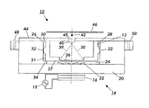
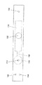
図15及び図16を参照すると、複式音響型液滴吐出機構を使用する多重エジェクタシステム260の構成が示されている。図15では、液滴吐出ユニット262はプレート268の適当なピン264、266、並びにプリント配線基板274の電源接続ピン270及びグラウンド帰還接続ピン272と接続され動作可能となる。試薬カートリッジ276内に保持されたバイオ流体が使い尽くされると、試薬カートリッジ276は除かれる。図16はこの状態を示している。試薬カートリッジ276を除いた場合、トランスジューサ/レンズ装置277を含む液滴吐出ユニット262の残りの部分は、接続ピン270及び272との接続を持続する。
【0047】
図13〜図16では、初めのバイオ流体のカートリッジを外した後で、代わりのバイオ流体のカートリッジをシステムの中に挿入することができる。これらの代わりのバイオ流体のカートリッジの挿入は、ロボットを使って行うことができる。前述したシステムは、図12のサブアレイを用いて実行することができる。さらに、図10〜図12に関連して説明した別の実施形態は、図13〜図16の装置に等しく適用できる。
【0048】
前述したように、本発明は、小さな面積の中に多数の液滴吐出ユニットを有する多重エジェクタシステムである。吐出される液滴は、生物学的分析に使用されるバイオ流体である。吐出された液滴が適切に形成され、適切に配置され、また意図された吐出位置に一致することが、本発明の使用目的に対して重要である。特定の生物学的分析に使用される多数の異なったバイオ流体があるため、目指すバイオ流体が目標とする液滴エジェクタの中に配置される保証があることが重要である。MESにバイオ流体が適切に充填されていることを確認する1つの方法は、各液滴吐出ユニットのバイオ流体のチャンバ内に蛍光マーカーを設置することである。蛍光マーカは特定の液滴吐出ユニットに固有であるため、適切な流体が意図した位置の適切な液滴吐出ユニットから吐出されていることを確認することができる。
【0049】
図17には、液滴吐出ユニット286の充填ポート284を介してバイオ流体282を供給するためのロボット充填システム280が示されている。ロボットシステム280は、図面では単純化されている。例えば、システム280には、液滴吐出ユニット286にバイオ流体及びマーカを分配する別個の分配ヘッドが含まれる。多くの異なった物質を液滴吐出ユニットに分配することができるシステム280は、この技術分野では周知である。充填動作は、液滴吐出と同じ位置又はこの位置から離れた位置で行うことができる。具体的には、液滴吐出ユニット286は充填され、次に、多重エジェクタシステムの位置に送られる。到着すると、液滴吐出ユニット286はここでシステムの中に設置される。あるいは、液滴吐出ユニット286は多重エジェクタシステムの設置されたままで充填される。
【0050】
本願で提供する品質管理方法及び品質管理工程は、バイオ流体が実際に液滴エジェクタの中に充填されたことを確認するための試験を行う。
【0051】
この品質管理を行う1つの実施形態は、液滴吐出動作の前に行われる。特に、いくつかの実施形態では、初期準備動作が行われることに注意されたい。この考えは、例えば、本願の図8の中に示されていた。真空システム144は、真空にしてバイオ流体を液滴吐出ユニットから吸引する。この動作の間に、吐出チャンバ内に含まれたある量のバイオ流体が、図8の使い捨て使い捨てチューブ146の少なくとも一部の中に吸引される。このため、永久ノズル142及び/又は使い捨てチューブ146は、初期準備動作の間に吐出された少量の流体を保持する。自動的に制御された初期準備装置が、図18の基板302上に移動され、真空装置を逆転させることにより、ノズル142及び/又はチュービング146内の材料が基板302上に吐出される。このように、初期準備用液滴300が基板302上に形成される。各液滴吐出ユニットに対して別々の永久ノズル142及び使い捨てチューブ146を用いることが必要である。
【0052】
つぎに、周知のスプリング動作によって、基板302を液滴の有無を検出する光学スキャナシステム304に通過させる。コントローラ306は、例えば、液滴の位置をノズルとマッチングさせる相関テーブルを持っている。これにより、特定の液滴吐出ユニットが対応付けられる。液滴が適当な位置で検出されない場合は、液滴吐出ユニットが正しくバイオ流体を搭載していないか又は適切に初期準備されていないことを示している。
【0053】
別の実施形態では、基板302上の液滴は、初期準備機構を使用することによって得ることはできないが、初期準備動作が行われた後に得られる。この実施形態では、試験サンプルが、生物学的分析の初期準備の前に作成及びスキャンされる。動作前試験は、液滴吐出ユニットが充填されて、用意されているかどうかを検出するだけではなく、複数の液滴吐出ユニットのそれぞれが動作可能な状態にあることを検出する。特に、個々の液滴吐出ユニットのプリントヘッドが動作していない場合、液滴はスポットを置くべき基板上には検出されない。このことは、液滴吐出ユニットが正しく搭載されていないか、又は正しく用意されていないことを示している。いずれの場合でも、検出された液滴吐出ユニットをより詳細に調査する必要がある。このため、この動作前試験は、バイオ流体の搭載を検証することだけでなく、適切な吐出動作が行われていることを検証するために使用することができる。前述した実施形態では、全ての液滴エジェクタに対して、バイオ流体の適切な配置及び液滴エジェクタの動作が確認試験される。別の実施形態では、各液滴吐出ユニットよりも少ない数が試験される。このシナリオでは、サンプリング動作を行って、システムが動作しているかどうかを決定する。このサンプリングは、動作確認に各液滴吐出ユニットをチェックするのではなく統計的な基準を使用している点で、前述した実施形態より正確ではない。この運用の利点は、試験速度が増加することである。
【0054】
図19は、多重エジェクタシステム内の液滴吐出ユニット312のような液滴吐出の適切な動作を検出するための別の実施形態を示している。具体的には、レーザビーム315が液滴吐出ユニット312によって吐出されたバイオ液滴316を横切るように、レーザ314が配置されている。レーザビーム検出器317が、レーザ314から入る信号を検出するように配置されている。このシステムは、液滴吐出ユニット312から飛行する液滴に対するレーザ散乱動作を利用している。検出器317からの検出結果は、コントローラ318に送られる。このコントローラ318は、液滴吐出ユニットが適切に動作しているかどうかを確定するためにどの液滴吐出ユニットを試験するかを決定する。この図は単一の液滴吐出ユニットを示しているが、複数のレーザ314及び検出器317のシステムを導入して、複数の液滴吐出ユニットを同時に検証することもできる。各液滴吐出ユニットを試験するために、多重エジェクタシステムを移動させ、又は、レーザ314及び検出器317の組合わせを多重エジェクタシステムの全体にわたって移動させることもできる。検出機構の変形例は、当業者には周知であろう。
【0055】
以上説明したように、多重エジェクタシステムは、100から1000以上の範囲にわたる複数の液滴吐出ユニットを極めて小さくコンパクトな面積の中で動作させることが目的であり、適切な動作についての検証は、液滴の位置決めの品質及び精度を向上させる重要な利点である。このため、場合によっては、2つ以上の実施形態が一つのシステムに用いられる。これにより、バイオ流体が適切に液滴吐出ユニットの中に充填されたこと、初期準備動作が適切に行われたこと、また液滴吐出ユニットが実際に正しく動作していることの確実性が向上する。
【0056】
概略検査、すなわち初期準備試験の実施形態では、実施形態の中で開示された光学スキャナ304は、液滴の位置及び組成の特異性はプライオリティが高く場合に、バイオ流体の存在のみを検出する試験に用いることができる。他方、より精巧なスキャニング動作を初期準備後の液滴に対して行うことで、液滴の存在だけでなく、それらの位置、組成及び寸法についてのより詳細な検証を確実できる。
【0057】
図20を参照すると、本発明の動作可能システム320が示されている。このシステム320には、バイオ流体の液滴を受けることができる基板ロール322が含まれる。この基板は、周知の基板運用機構によって、多重エジェクタシステム324を通過するように移動される。この多重エジェクタシステム324には、移動する基板上の所定の位置にバイオ流体の液滴を滴下するように配列された、複数の液滴吐出ユニットが含まれる。1つの実施形態では、全ての液滴吐出ユニットが、通過する基板上に絶えず液滴を吐出する。液滴が確実に適切に配置されるように、基板の速度がコントロールされて、生物学的分析物326を作成する。次に、生物学的分析物326は、光学スキャナシステム328を通過する。この構成では、生物学的分析物326内の各液滴が試験されて、適切な吐出動作が確認される。このため、前述した実施形態では、多重エジェクタシステムの試験は生物学的分析の液滴吐出の前に行われたが、この実施形態では、作成された各生物学的分析物のそれぞれ又はいくつかのサブセットが試験される。作成された生物学的分析物は、連続ロール322上に保持されるか、又は、シートに別々に切り離される。
【0058】
滴下された基板上のバイオ流体についての実際の試験は、液滴間の何らかの相互作用を発見することが目的である。このため、システム320は、単一のスペースに2つ以上の液滴を吐出することができる。または、点線で示したさらに別の多重吐出システム330をシステム320の中に備えて、第2の液滴のセットを提供することができる。さらに別の光学スキャナシステム332をこの場合も備えて、第2の液滴が適切に吐出されているかどうかを検出できる。2つ以上の多重エジェクタシステムに対して単一の光学スキャナシステムしか備えていない場合、最後の液滴が吐出された後に検出が行われる。
【0059】
音響型液滴吐出ユニット及び圧電型液滴吐出ユニットについての実施形態を述べているが、本発明は、他の液滴吐出機構及び汚染を避けることが有益なバイオ流体以外の流体に対しても適用できる。
【図面の簡単な説明】
【図1】 音響型液滴吐出機構内に挿入された試薬カートリッジの断面図である。
【図2】 別の実施形態の単式音響型液滴吐出機構の平面図である。
【図3】 別の実施形態の単式音響型液滴吐出機構の側面図である。
【図4】 単式圧電型液滴吐出機構を示す図である。
【図5】 単式圧電型液滴吐出機構を示す図である。
【図6】 複式圧電型液滴吐出機構を示す図である。
【図7】 複式圧電型液滴吐出機構を示す図である。
【図8】 単式及び複式圧電型液滴吐出機構に使用される使い捨て式プライマー接続体を示す図である。
【図9】 多重エジェクタシステムを示す図である。
【図10】 単式のエジェクタ機構を有する多重エジェクタシステムの側面図である。
【図11】 単式のエジェクタ機構を有する多重エジェクタシステムの別の実施形態を示す図である。
【図12】 エジェクタのサブアレイで構成される多重エジェクタシステムの正面図である。
【図13】 複式圧電型液滴エジェクタが設置された多重エジェクタシステムを示す図である。
【図14】 複式圧電型液滴エジェクタが取り外された多重エジェクタシステムを示す図である。
【図15】 複式音響型液滴吐出エジェクタが設置された多重エジェクタシステムを示す図である。
【図16】 複式音響型液滴吐出エジェクタが設置された多重エジェクタシステムを示す図である。
【図17】 バイオ流体を供給するロボット充填手段を示す図である。
【図18】 本発明による初期準備試験を示す図である。
【図19】 液滴エジェクタの動作確認用のレーザ散乱検出器を説明する図である。
【図20】 本発明を用いたシステムを説明する図である。
【符号の説明】
14 音響型液滴吐出機構、12,112,276 試薬カートリッジ、10,152,153,154,156,232,262,286,312 液滴吐出ユニット、16,244 トランスジューサ、18,96,126 電源、20 基板、24 音響結合層、22 フレネルレンズ、30 チャンバ、26,28 壁、31 側壁、32 シール、34 ストッパ、36,72 薄膜、37 下面、38,282 バイオ流体、39 音響エネルギー波、40 メニスカス、46,186,302 基板、44 蓋、45 アパーチャ、42,184,316 バイオ液滴、48,50,52,98,100,102,134,136,138 位置合わせ溝、60 単式音響型液滴吐出ユニット、62,82,116 吐出用リザーバ、64,84,118 メインリザーバ、66,86,120 リザーバ結合部、68,88,122,178,284 充填ポート、80 圧電型液滴吐出ユニット、90,124 圧電アクチュエータ、92下面、94,114,250 吐出用ノズル、110 複式圧電型液滴吐出ユニット、128 再利用フレーム、130 ダイアフラム、132 弾力性の膜、140 プライマー接続体、142 永久ノズル、144 真空ユニット、146 使い捨てチューブ、148 液面検出センサ、150,190,210,230,260,324,330 多重エジェクタシステム(MES)、158,202,220,268 プレート、160,162,164 円錐チップ状ピン、166,192,242,274 プリント配線基板、168,194,238,270 電源接続ピン、170,196,240,272 グラウンド帰還接続ピン、172 電気配線、174 ドライバチップ、176 ノズル又はアパーチャ、180,182 スルーホール、188 定位電位、198,200 開口部、204,206,216,218,220,234,236,264,266 ピン、207,208 ストッパ、214 サブアレイ、252バイオ流体保持部分、277 トンラスジューサ及びレンズ部分、280 ロボット充填システム、300 初期準備用液滴、304,328,332 光学スキャナシステム、306,318 コントローラ、314 レーザ、315 レーザビーム、317 レーザビーム検出器、320 動作可能システム、322 基板ロール、326 生物学的分析物。[0001]
BACKGROUND OF THE INVENTION
The present invention relates to a multiple ejector system that implements a plurality of biofluid ejectors arranged to create a biological analyte.
[0002]
[Prior art]
Many scientific tests, such as tests for biology, genetics, pharmacology and medicine, use a sequence or array of biofluid droplets on which the tests are performed. In some tests, thousands of biofluidic droplets are dropped onto a single substrate containing various specialized biofluids. For example, in current biological tests for genetic defects and other biochemical abnormalities, thousands of individual biofluids are placed at different locations on the glass substrate. Thereafter, another biofluid is dropped at the same location to obtain an interaction. This created biological analyte is then scanned with a laser to observe changes in physical properties.
[0003]
[Problems to be solved by the invention]
In this case, it is important that the droplet ejection device is not a source of contamination or does not cause cross-contamination between biofluids. Another consideration in droplet ejection for biological analysis is the high cost of biofluids used in such experiments. For this reason, it is desirable to minimize the volume of biofluid required to perform biological analysis. Current devices used to perform biological analysis lack the ability to accurately dispense biofluidic droplets so as to avoid contamination and cross-contamination. Current devices also use more than the desired volume of biofluid and use time consuming processes to perform biological analysis.
[0004]
Therefore, a bio that avoids contamination and cross-contamination, uses only a small amount of biofluid in the droplet ejection process, and can achieve high throughput that makes droplet ejection for biological analysis extremely efficient and economical. Development of a multiple ejector system for discharging fluid has been desired.
[0005]
[Means for Solving the Problems]
A multiple ejector system for printing an array of biofluids includes a plate having a plurality of sets of pins extending outwardly from the surface of the plate. A printed wiring board having a pair of power connection pins and ground return connection pins extending from the surface of the printed wiring board is included. A plurality of biofluid droplet ejection units are provided, and these units include alignment grooves and transducers. Each of the plurality of biofluid droplet ejection units is attached to one of the corresponding set of pins by fitting the pins and alignment grooves. The power supply connection pins are connected to the respective transducers to be in an operation state, and the ground return connection pins are connected to the body portion of the droplet discharge unit to be in an operation state. The droplet discharge unit includes various biofluids discharged on the substrate. Confirmation of the droplet ejection unit containing the biofluid can be performed in one embodiment by using an optical scanner. By detecting the droplet at a defined location, it is verified that a suitably shaped spot exists on the substrate and is in the correct location.
[0006]
DETAILED DESCRIPTION OF THE INVENTION
FIG. 1 shows a cross-sectional view of a
[0007]
The acoustic coupling layer can be an
[0008]
On top of the
[0009]
In operation, when the
[0010]
The surface from which the biofluid droplets are ejected is either entirely open or covered with an aperture plate or
[0011]
The above-described design isolates the
[0012]
In a specific design example of the present invention, the diameter of the transducer and lens is about 300 microns, and the thickness of the
[0013]
The
[0014]
The
[0015]
2 and 3 show a single acoustic
[0016]
2 and 3, the
[0017]
Referring to FIGS. 4 and 5, a side view and a plan view of a single-type disposable piezoelectric
[0018]
In operation, the
[0019]
When the biofluid droplet is ejected from the
[0020]
As can be understood from FIG. 4, the
[0021]
6 and 7 are a side view and a plan view of the dual piezoelectric
[0022]
A resilient
[0023]
The disclosed biofluid droplet ejection unit functions using a small amount of biofluid in the main and ejection reservoirs. For example, the main reservoir, in one example, contains 50 to 150 microliters of biofluid when full, while the discharge reservoir contains 5 to 25 microliters of biofluid when full. For this reason, it can be seen that the described ejector unit can operate with a very small amount of biofluid. Biofluid droplets themselves are in the picoliter range. Since many of the biofluids used are expensive, operating in small quantities is an important feature for ejector units. Also, since only a very small amount of biofluid is required, using a disposable ejector unit is an attractive option.
[0024]
It can be seen that the units described above operate with high efficiency and that little biofluid remains. This is due to both the operational characteristics of the unit itself and the fact that only a small amount of biofluid is required to operate the unit. In particular, due to the small amount of biofluid originally used, high operational efficiencies are achieved even if there is residue in the system. In one preferred embodiment, 80% or more of the biofluid can be used under normal operation.
[0025]
In the above description, it is stated that the main reservoir has 50 to 150 microliters and the discharge reservoir has 5 to 25 microliters, but these amounts are the size of the droplets used, the amount of discharge performed, the usage Depending on the type of biofluid being used, as well as other parameters.
[0026]
The ratio of the amount of biofluid between the main reservoir and the discharge reservoir is preferably 2: 1 to 10: 1. When set to this range, the disclosed embodiments can achieve aspiration of the biofluid with a suitable surface tension while using the desired small amount. However, larger ratios can also be selected based on factors including the cost of the biofluid and the intended use of the ejector.
[0027]
FIG. 8 shows a
[0028]
The application of the droplet ejection mechanism is to create a biological analyte that includes a number of different biofluid droplets. A biological droplet ejection system employing multiple droplet ejection units of the type just described is described below. This system can create arrays of various biological materials such as DNA and proteins.
[0029]
FIG. 9 shows a multiple ejector system (MES) 150 that enables droplet ejection for high density biological analysis. The
[0030]
The
[0031]
[0032]
As shown in the figure, either a nozzle or an aperture 176 is included depending on whether the
[0033]
Referring to FIG. 10, a side view of the single
[0034]
A
[0035]
FIG. 11 is a side view of a
[0036]
In the above description, the
[0037]
Still other embodiments of the apparatus shown in FIGS. 10 and 11 are also conceivable. Although two connecting pins or spring-loaded pins, shown as 168 and 170 in FIG. 10 and 194 and 196 in FIG. 11, are shown to provide power and ground feedback, a single spring-loaded pin should be used. You can also. In an embodiment using a single spring pin, the power pins 168 or 194 of FIGS. 10 and 11 are used as is. However, the return or ground contact spring loaded
[0038]
[0039]
Referring to FIG. 12, a top view of yet another
[0040]
In order to further improve the positioning of the droplet ejector, the connection pins as described in connection with FIGS. 10-12 are designed to provide some flexibility in the pin structure. This flexibility is useful for finer alignment of the droplet ejector once connected to the pin. While the plate and the pins extending from it and the connection holes on the droplet ejector are manufactured with high accuracy, the pins are designed to have springs or flexibility so that further alignment accuracy can be obtained. it can. Such pins allow the droplet ejector to move in the horizontal X and Y planes so that the ejector is accurately aligned with the discharge position. In another embodiment, the through-hole formed in the droplet ejector unit is manufactured by using a spring or a flexible circumferential member, so that it can be securely connected to the pin and in the horizontal plane of X and Y. Will be able to move flexibly.
[0041]
Further, the alignment groove of the droplet ejector can be formed by a V-groove or another design that can move the pin to more accurately align the ejector. Such alignment elements and processes are well known in the field of alignment.
[0042]
Furthermore, in the above-described embodiment, the set of pins holding the droplet ejector unit uses three pins, but other sets of pins are possible. For example, in some cases, a 2-pin, 4-pin or other tweezer arrangement is optimal.
[0043]
10 and 11 show a multiple ejector system using a single droplet discharge unit for both the piezoelectric droplet discharge mechanism and the acoustic droplet discharge mechanism. FIGS. 13 to 16 show side views of the multi-ejector system configuration for the dual piezoelectric droplet discharge mechanism and the dual acoustic droplet discharge mechanism.
[0044]
FIG. 13 shows a side view of the
[0045]
When the biofluid of the droplet ejection unit of FIG. 13 is used up, only the portion of the unit that contains the fluid is removed. As previously mentioned, the transducer portion remains in the system. FIG. 14 shows that the portion of the unit containing the fluid has been removed.
[0046]
Referring to FIGS. 15 and 16, the configuration of a
[0047]
In FIGS. 13-16, after the initial biofluidic cartridge is removed, an alternative biofluidic cartridge can be inserted into the system. The insertion of these alternative biofluidic cartridges can be performed using a robot. The system described above can be implemented using the subarray of FIG. Furthermore, the other embodiments described in connection with FIGS. 10-12 are equally applicable to the apparatus of FIGS.
[0048]
As described above, the present invention is a multiple ejector system having a large number of droplet discharge units in a small area. The ejected droplet is a biofluid used for biological analysis. It is important for the intended use of the present invention that the ejected droplets are properly formed, properly positioned and matched to the intended ejection location. Since there are many different biofluids that are used for a particular biological analysis, it is important that there is a guarantee that the target biofluid will be placed in the target droplet ejector. One way to verify that the MES is properly filled with biofluid is to place a fluorescent marker in the biofluid chamber of each droplet ejection unit. Since the fluorescent marker is specific to a specific droplet discharge unit, it can be confirmed that an appropriate fluid is discharged from the appropriate droplet discharge unit at the intended position.
[0049]
FIG. 17 illustrates a
[0050]
The quality control method and the quality control process provided in the present application perform a test for confirming that the biofluid is actually filled in the droplet ejector.
[0051]
One embodiment for performing this quality control is performed before the droplet discharge operation. In particular, it should be noted that in some embodiments, an initial preparation operation is performed. This idea was shown, for example, in FIG. 8 of the present application. The
[0052]
Next, the
[0053]
In another embodiment, the droplets on the
[0054]
FIG. 19 illustrates another embodiment for detecting proper operation of droplet ejection, such as the
[0055]
As described above, the multiple ejector system is intended to operate a plurality of droplet discharge units ranging from 100 to 1000 or more in a very small and compact area. This is an important advantage that improves the quality and accuracy of drop positioning. For this reason, in some cases, two or more embodiments are used in one system. This improves the certainty that the biofluid has been properly filled into the droplet ejection unit, that the initial preparation operation has been performed properly, and that the droplet ejection unit is actually operating correctly. To do.
[0056]
In a rough inspection, or initial readiness test embodiment, the
[0057]
Referring to FIG. 20, an
[0058]
The actual test for the biofluid on the dropped substrate is aimed at finding any interaction between the droplets. Thus, the
[0059]
While embodiments of acoustic droplet ejection units and piezoelectric droplet ejection units have been described, the present invention is also applicable to other droplet ejection mechanisms and fluids other than biofluids where it is beneficial to avoid contamination. Applicable.
[Brief description of the drawings]
FIG. 1 is a cross-sectional view of a reagent cartridge inserted into an acoustic droplet discharge mechanism.
FIG. 2 is a plan view of a single acoustic droplet discharge mechanism according to another embodiment.
FIG. 3 is a side view of a single acoustic droplet discharge mechanism of another embodiment.
FIG. 4 is a view showing a single piezoelectric droplet discharge mechanism.
FIG. 5 is a diagram showing a single piezoelectric droplet discharge mechanism.
FIG. 6 is a diagram showing a double piezoelectric droplet discharge mechanism.
FIG. 7 is a diagram showing a double piezoelectric droplet discharge mechanism.
FIG. 8 is a view showing a disposable primer connection body used in a single-type and double-type piezoelectric droplet discharge mechanism.
FIG. 9 shows a multiple ejector system.
FIG. 10 is a side view of a multiple ejector system having a single ejector mechanism.
FIG. 11 shows another embodiment of a multiple ejector system having a single ejector mechanism.
FIG. 12 is a front view of a multiple ejector system composed of sub-arrays of ejectors.
FIG. 13 is a diagram showing a multiple ejector system in which a double piezoelectric droplet ejector is installed.
FIG. 14 is a diagram showing a multiple ejector system with a double piezoelectric droplet ejector removed.
FIG. 15 is a diagram showing a multiple ejector system in which a compound acoustic droplet discharge ejector is installed.
FIG. 16 is a diagram showing a multiple ejector system in which a compound acoustic droplet ejection ejector is installed.
FIG. 17 is a view showing a robot filling means for supplying a biofluid.
FIG. 18 is a diagram showing an initial preparation test according to the present invention.
FIG. 19 is a diagram for explaining a laser scattering detector for confirming the operation of a droplet ejector.
FIG. 20 is a diagram illustrating a system using the present invention.
[Explanation of symbols]
14 Acoustic droplet discharge mechanism, 12, 112, 276 Reagent cartridge, 10, 152, 153, 154, 156, 232, 262, 286, 312 Droplet discharge unit, 16,244 transducer, 18, 96, 126 Power supply, 20 substrate, 24 acoustic coupling layer, 22 Fresnel lens, 30 chamber, 26, 28 wall, 31 side wall, 32 seal, 34 stopper, 36, 72 thin film, 37 bottom surface, 38,282 biofluid, 39 acoustic energy wave, 40 meniscus 46,186,302 Substrate, 44 lid, 45 aperture, 42,184,316 bio droplet, 48,50,52,98,100,102,134,136,138 alignment groove, 60 single acoustic droplet Discharge unit, 62, 82, 116 Discharge reservoir, 64, 84, 118 Main Server, 66, 86, 120 Reservoir coupling portion, 68, 88, 122, 178, 284 Filling port, 80 Piezoelectric droplet discharge unit, 90, 124 Piezoelectric actuator, 92 bottom surface, 94, 114, 250 Discharge nozzle, 110 Dual-type piezoelectric droplet discharge unit, 128 reuse frame, 130 diaphragm, 132 elastic membrane, 140 primer connection body, 142 permanent nozzle, 144 vacuum unit, 146 disposable tube, 148 liquid level detection sensor, 150, 190, 210 , 230, 260, 324, 330 Multiple Ejector System (MES), 158, 202, 220, 268 Plate, 160, 162, 164 Conical Tip Pin, 166, 192, 242, 274 Printed Circuit Board, 168, 194, 238 270 Power connection pin 170,196,240,272 Ground feedback connection pin, 172 Electrical wiring, 174 Driver chip, 176 Nozzle or aperture, 180,182 Through hole, 188 Localization potential, 198,200 Opening, 204,206,216,218,220 , 234, 236, 264, 266 pins, 207, 208 stoppers, 214 sub-array, 252 biofluid holding part, 277 tonlas juicer and lens part, 280 robot filling system, 300 initial preparation droplet, 304, 328, 332 optics Scanner system, 306, 318 controller, 314 laser, 315 laser beam, 317 laser beam detector, 320 ready system, 322 substrate roll, 326 biological analyte.
Claims (2)
弾力性のチューブが周りを取り巻いている永久ノズルを有する真空ユニットを備えた初期準備システムを、多重エジェクタシステムの液滴吐出ユニットに接触させるステップと、
液滴吐出ユニット内に存在する流体を、少なくとも1つの永久ノズル及び弾力性のチューブの中に吸引させる吸引動作を実施するステップと、
初期準備システムの多重エジェクタシステムとの接触を外すステップと、
初期準備システムを試験基板上に移動させるステップと、
吸引動作を逆転させて、永久ノズル又はチューブ内の流体を試験基板上に吐出させるステップと、
試験基板をスキャニングして、特定の液滴吐出ユニットに対応する真空ユニットが流体を放出したかどうかを検出するステップと、
スキャニングから、多重エジェクタシステムの液滴吐出ユニットが流体で充填されているかどうかを確定するステップと、
を備えることを特徴とする方法。An inspection method for a bio- droplet discharge unit included in a multiple ejector system,
Contacting an initial preparation system comprising a vacuum unit with a permanent nozzle around which a resilient tube surrounds a droplet ejection unit of a multiple ejector system;
Performing a suction operation to suck the fluid present in the droplet discharge unit into at least one permanent nozzle and a resilient tube;
Disconnecting the initial preparation system from the multiple ejector system;
Moving the initial preparation system onto the test substrate;
Reversing the suction operation to discharge the fluid in the permanent nozzle or tube onto the test substrate;
Scanning the test substrate to detect whether a vacuum unit corresponding to a particular droplet ejection unit has released fluid;
Determining from scanning the droplet ejection unit of the multiple ejector system is filled with fluid;
A method comprising the steps of:
多重エジェクタシステムの各バイオ流体の液滴吐出ユニットを検査することを特徴とする方法。An inspection method for a droplet discharge unit according to claim 1,
Inspecting each biofluid droplet ejection unit of a multiple ejector system.
Applications Claiming Priority (2)
| Application Number | Priority Date | Filing Date | Title |
|---|---|---|---|
| US09/718,733 | 2000-11-22 | ||
| US09/718,733 US6740530B1 (en) | 2000-11-22 | 2000-11-22 | Testing method and configurations for multi-ejector system |
Publications (2)
| Publication Number | Publication Date |
|---|---|
| JP2002236128A JP2002236128A (en) | 2002-08-23 |
| JP4024523B2 true JP4024523B2 (en) | 2007-12-19 |
Family
ID=24887276
Family Applications (1)
| Application Number | Title | Priority Date | Filing Date |
|---|---|---|---|
| JP2001354720A Expired - Fee Related JP4024523B2 (en) | 2000-11-22 | 2001-11-20 | Inspection method for multiple ejector systems |
Country Status (4)
| Country | Link |
|---|---|
| US (1) | US6740530B1 (en) |
| EP (1) | EP1208912B1 (en) |
| JP (1) | JP4024523B2 (en) |
| DE (1) | DE60119874T2 (en) |
Families Citing this family (10)
| Publication number | Priority date | Publication date | Assignee | Title |
|---|---|---|---|---|
| EP1274508B1 (en) * | 2000-04-03 | 2007-12-05 | Parabol Technologies S.A. | A device for dispensing accurately-controlled small doses of liquid |
| US8122880B2 (en) * | 2000-12-18 | 2012-02-28 | Palo Alto Research Center Incorporated | Inhaler that uses focused acoustic waves to deliver a pharmaceutical product |
| US6943036B2 (en) * | 2001-04-30 | 2005-09-13 | Agilent Technologies, Inc. | Error detection in chemical array fabrication |
| WO2003006164A1 (en) * | 2001-07-11 | 2003-01-23 | Universisty Of Southern California | Dna probe synthesis on chip on demand by mems ejector array |
| US20040259261A1 (en) * | 2003-06-20 | 2004-12-23 | Phalanx Biotech Group, Inc. | Method for manufacturing a microarray and verifying the same |
| JP4441336B2 (en) | 2004-06-11 | 2010-03-31 | 日本碍子株式会社 | Manufacturing method of microarray |
| US7600840B2 (en) | 2005-08-12 | 2009-10-13 | Samsung Electronics Co., Ltd. | Device for printing droplet or ink on substrate or paper |
| US7909424B2 (en) * | 2007-07-31 | 2011-03-22 | Hewlett-Packard Development Company, L.P. | Method and system for dispensing liquid |
| KR101102532B1 (en) * | 2008-07-10 | 2012-01-03 | 삼성전자주식회사 | Cartridge containing reagent therein, microfluidic device having the cartridge, manufacturing method of the microfluidic device, biochemistry analysis method using microfluidic device |
| WO2017090427A1 (en) * | 2015-11-26 | 2017-06-01 | 富士フイルム株式会社 | Solution deposition device and solution deposition method |
Family Cites Families (49)
| Publication number | Priority date | Publication date | Assignee | Title |
|---|---|---|---|---|
| JPS58194564A (en) | 1982-05-11 | 1983-11-12 | Canon Inc | Ink jet printer |
| US4633274A (en) | 1984-03-30 | 1986-12-30 | Canon Kabushiki Kaisha | Liquid ejection recording apparatus |
| US4797693A (en) | 1987-06-02 | 1989-01-10 | Xerox Corporation | Polychromatic acoustic ink printing |
| JPH0457181A (en) | 1990-06-26 | 1992-02-24 | Toshiba Corp | Method and device for configuring multiplex neural circuit network |
| DE4024545A1 (en) | 1990-08-02 | 1992-02-06 | Boehringer Mannheim Gmbh | Metered delivery of biochemical analytical soln., esp. reagent |
| US5229793A (en) | 1990-12-26 | 1993-07-20 | Xerox Corporation | Liquid surface control with an applied pressure signal in acoustic ink printing |
| US5250962A (en) | 1991-10-16 | 1993-10-05 | Xerox Corporation | Movable ink jet priming station |
| JP3144948B2 (en) | 1992-05-27 | 2001-03-12 | 日本碍子株式会社 | Inkjet print head |
| JP3317308B2 (en) | 1992-08-26 | 2002-08-26 | セイコーエプソン株式会社 | Laminated ink jet recording head and method of manufacturing the same |
| JP3144949B2 (en) | 1992-05-27 | 2001-03-12 | 日本碍子株式会社 | Piezoelectric / electrostrictive actuator |
| ATE170293T1 (en) | 1992-06-08 | 1998-09-15 | Behring Diagnostics Inc | FLUID DISPENSER SYSTEM |
| US5450105A (en) | 1993-04-30 | 1995-09-12 | Hewlett-Packard Company | Manual pen selection for clearing nozzles without removal from pen carriage |
| US5796417A (en) | 1993-10-29 | 1998-08-18 | Hewlett-Packard Company | Compliant interconnect assembly for mounting removable print cartridges in a carriage |
| US5684518A (en) | 1993-10-29 | 1997-11-04 | Hewlett-Packard Company | Interconnect scheme for mounting differently configured printheads on the same carriage |
| DE69532916D1 (en) * | 1994-01-28 | 2004-05-27 | Schneider Medical Technologies | METHOD AND DEVICE FOR IMAGING |
| FR2720030B1 (en) | 1994-05-19 | 1996-08-09 | Jean Francille | Device for mounting printing sleeves on cylinders supporting flexographic machines. |
| US5807522A (en) * | 1994-06-17 | 1998-09-15 | The Board Of Trustees Of The Leland Stanford Junior University | Methods for fabricating microarrays of biological samples |
| US5715327A (en) * | 1994-09-20 | 1998-02-03 | Neopath, Inc. | Method and apparatus for detection of unsuitable conditions for automated cytology scoring |
| US5638459A (en) * | 1994-09-20 | 1997-06-10 | Neopath, Inc. | Method and apparatus for detecting a microscope slide coverslip |
| JPH08254446A (en) | 1995-03-16 | 1996-10-01 | Fujitsu Ltd | Ultrasonic printing method and device as well as formation of acoustic lens |
| WO1997004418A1 (en) * | 1995-07-19 | 1997-02-06 | Morphometrix Technologies Inc. | Multi-spectral segmentation for image analysis |
| US5658802A (en) | 1995-09-07 | 1997-08-19 | Microfab Technologies, Inc. | Method and apparatus for making miniaturized diagnostic arrays |
| US6418236B1 (en) * | 1999-06-24 | 2002-07-09 | Chromavision Medical Systems, Inc. | Histological reconstruction and automated image analysis |
| US5958342A (en) | 1996-05-17 | 1999-09-28 | Incyte Pharmaceuticals, Inc. | Jet droplet device |
| US6381353B1 (en) * | 1996-08-30 | 2002-04-30 | Marvin Weiss | System for counting colonies of micro-organisms in petri dishes and other culture media |
| US6122396A (en) * | 1996-12-16 | 2000-09-19 | Bio-Tech Imaging, Inc. | Method of and apparatus for automating detection of microorganisms |
| US5877580A (en) | 1996-12-23 | 1999-03-02 | Regents Of The University Of California | Micromachined chemical jet dispenser |
| AU751956B2 (en) | 1997-03-20 | 2002-09-05 | University Of Washington | Solvent for biopolymer synthesis, solvent microdroplets and methods of use |
| EP0865824B1 (en) | 1997-03-20 | 2004-05-19 | F. Hoffmann-La Roche Ag | Micromechanical pipetting device |
| DE69823904T2 (en) | 1997-03-20 | 2005-06-16 | F. Hoffmann-La Roche Ag | Micromechanical pipetting device |
| JPH10286974A (en) | 1997-04-14 | 1998-10-27 | Brother Ind Ltd | Ink jet printer |
| US5943075A (en) | 1997-08-07 | 1999-08-24 | The Board Of Trustees Of The Leland Stanford Junior University | Universal fluid droplet ejector |
| DE19754000A1 (en) | 1997-12-05 | 1999-06-17 | Max Planck Gesellschaft | Device and method for the electrically triggered microdrop delivery with a dispensing head |
| US6165417A (en) | 1998-10-26 | 2000-12-26 | The Regents Of The University Of California | Integrated titer plate-injector head for microdrop array preparation, storage and transfer |
| IL127484A (en) | 1998-12-09 | 2001-06-14 | Aprion Digital Ltd | Printing device comprising a laser and method for same |
| JP2002542455A (en) | 1999-02-19 | 2002-12-10 | ゲーシム・ゲゼルシャフト・フューア・ジリーツィウム−ミクロジステーメ・ミト・ベシュレンクテル・ハフツング | Sensor that controls the function of the micropipette-measurement area |
| US6627157B1 (en) | 1999-03-04 | 2003-09-30 | Ut-Battelle, Llc | Dual manifold system and method for fluid transfer |
| AU762085B2 (en) * | 1999-04-13 | 2003-06-19 | Chromavision Medical Systems, Inc. | Histological reconstruction and automated image analysis |
| US6242266B1 (en) | 1999-04-30 | 2001-06-05 | Agilent Technologies Inc. | Preparation of biopolymer arrays |
| US6195451B1 (en) * | 1999-05-13 | 2001-02-27 | Advanced Pathology Ststems, Inc. | Transformation of digital images |
| US6453060B1 (en) * | 1999-06-29 | 2002-09-17 | Tri Path Imaging, Inc. | Method and apparatus for deriving separate images from multiple chromogens in a branched image analysis system |
| JP2001186881A (en) | 1999-10-22 | 2001-07-10 | Ngk Insulators Ltd | Method for producing dna chip |
| JP2001186880A (en) | 1999-10-22 | 2001-07-10 | Ngk Insulators Ltd | Method for producing dna chip |
| US6656432B1 (en) | 1999-10-22 | 2003-12-02 | Ngk Insulators, Ltd. | Micropipette and dividedly injectable apparatus |
| ATE358277T1 (en) | 1999-10-22 | 2007-04-15 | Ngk Insulators Ltd | DNA CHIP AND METHOD FOR PRODUCING THE SAME |
| US6362004B1 (en) * | 1999-11-09 | 2002-03-26 | Packard Biochip Technologies, Llc | Apparatus and method for using fiducial marks on a microarray substrate |
| US20030048341A1 (en) | 2000-09-25 | 2003-03-13 | Mutz Mitchell W. | High-throughput biomolecular crystallization and biomolecular crystal screening |
| US6466690C1 (en) * | 2000-12-19 | 2008-11-18 | Bacus Res Lab Inc | Method and apparatus for processing an image of a tissue sample microarray |
| US6869551B2 (en) | 2001-03-30 | 2005-03-22 | Picoliter Inc. | Precipitation of solid particles from droplets formed using focused acoustic energy |
-
2000
- 2000-11-22 US US09/718,733 patent/US6740530B1/en not_active Expired - Fee Related
-
2001
- 2001-11-13 EP EP01126952A patent/EP1208912B1/en not_active Expired - Lifetime
- 2001-11-13 DE DE60119874T patent/DE60119874T2/en not_active Expired - Lifetime
- 2001-11-20 JP JP2001354720A patent/JP4024523B2/en not_active Expired - Fee Related
Also Published As
| Publication number | Publication date |
|---|---|
| EP1208912A3 (en) | 2003-08-06 |
| DE60119874T2 (en) | 2006-09-28 |
| US6740530B1 (en) | 2004-05-25 |
| JP2002236128A (en) | 2002-08-23 |
| DE60119874D1 (en) | 2006-06-29 |
| EP1208912A2 (en) | 2002-05-29 |
| EP1208912B1 (en) | 2006-05-24 |
Similar Documents
| Publication | Publication Date | Title |
|---|---|---|
| JP4028716B2 (en) | Multiple ejector system for dispensing biofluids | |
| EP1137489B1 (en) | Fluid dispenser and dispensing methods | |
| US20010036424A1 (en) | Liquid pipetting apparatus and micro array manufacturing apparatus | |
| JP3598066B2 (en) | Fluid control device with format conversion function | |
| US20020168297A1 (en) | Method and device for dispensing of droplets | |
| US20030059949A1 (en) | Droplet dispensing system | |
| EP1209466B1 (en) | Level sense and control system for biofluid drop ejection devices | |
| US6401769B1 (en) | Apparatus for dispensing a predetermined volume of a liquid | |
| JP4024523B2 (en) | Inspection method for multiple ejector systems | |
| US6861034B1 (en) | Priming mechanisms for drop ejection devices | |
| JP3809086B2 (en) | Liquid dispensing device | |
| JP2009523243A (en) | Ink jet apparatus and method for discharging a plurality of substances onto a substrate | |
| US6713022B1 (en) | Devices for biofluid drop ejection | |
| JP2004513376A (en) | Apparatus and system for dispensing or aspirating / dispensing a liquid sample | |
| JP2008249720A (en) | Droplet dispensing system | |
| WO2002092228A2 (en) | A method and device for dispensing of droplets | |
| JP2007057384A (en) | Droplet discharge head, droplet discharge device, and manufacturing method of microarray | |
| IE20020333A1 (en) | A method and device for dispensing of droplets | |
| JP2006337149A (en) | Liquid-filling method of liquid droplet discharge head, fixing holder of liquid droplet discharge head and cleaning method of liquid droplet discharge head |
Legal Events
| Date | Code | Title | Description |
|---|---|---|---|
| A621 | Written request for application examination |
Free format text: JAPANESE INTERMEDIATE CODE: A621 Effective date: 20041116 |
|
| RD04 | Notification of resignation of power of attorney |
Free format text: JAPANESE INTERMEDIATE CODE: A7424 Effective date: 20041116 |
|
| A977 | Report on retrieval |
Free format text: JAPANESE INTERMEDIATE CODE: A971007 Effective date: 20051027 |
|
| A131 | Notification of reasons for refusal |
Free format text: JAPANESE INTERMEDIATE CODE: A131 Effective date: 20070724 |
|
| A521 | Written amendment |
Free format text: JAPANESE INTERMEDIATE CODE: A523 Effective date: 20070831 |
|
| TRDD | Decision of grant or rejection written | ||
| A01 | Written decision to grant a patent or to grant a registration (utility model) |
Free format text: JAPANESE INTERMEDIATE CODE: A01 Effective date: 20070925 |
|
| A61 | First payment of annual fees (during grant procedure) |
Free format text: JAPANESE INTERMEDIATE CODE: A61 Effective date: 20071003 |
|
| R150 | Certificate of patent or registration of utility model |
Free format text: JAPANESE INTERMEDIATE CODE: R150 |
|
| FPAY | Renewal fee payment (event date is renewal date of database) |
Free format text: PAYMENT UNTIL: 20101012 Year of fee payment: 3 |
|
| FPAY | Renewal fee payment (event date is renewal date of database) |
Free format text: PAYMENT UNTIL: 20111012 Year of fee payment: 4 |
|
| FPAY | Renewal fee payment (event date is renewal date of database) |
Free format text: PAYMENT UNTIL: 20121012 Year of fee payment: 5 |
|
| FPAY | Renewal fee payment (event date is renewal date of database) |
Free format text: PAYMENT UNTIL: 20121012 Year of fee payment: 5 |
|
| FPAY | Renewal fee payment (event date is renewal date of database) |
Free format text: PAYMENT UNTIL: 20131012 Year of fee payment: 6 |
|
| R250 | Receipt of annual fees |
Free format text: JAPANESE INTERMEDIATE CODE: R250 |
|
| R250 | Receipt of annual fees |
Free format text: JAPANESE INTERMEDIATE CODE: R250 |
|
| LAPS | Cancellation because of no payment of annual fees |