JP4022344B2 - Rotating color filter unit and projection system using the same - Google Patents
Rotating color filter unit and projection system using the same Download PDFInfo
- Publication number
- JP4022344B2 JP4022344B2 JP27334799A JP27334799A JP4022344B2 JP 4022344 B2 JP4022344 B2 JP 4022344B2 JP 27334799 A JP27334799 A JP 27334799A JP 27334799 A JP27334799 A JP 27334799A JP 4022344 B2 JP4022344 B2 JP 4022344B2
- Authority
- JP
- Japan
- Prior art keywords
- color filter
- filter unit
- rotating
- mounting base
- cover
- Prior art date
- Legal status (The legal status is an assumption and is not a legal conclusion. Google has not performed a legal analysis and makes no representation as to the accuracy of the status listed.)
- Expired - Lifetime
Links
Images


Landscapes
- Projection Apparatus (AREA)
Description
【0001】
【発明の属する技術分野】
本発明は、回転体の騒音防止装置又は回転体の騒音防止技術に係わり、特に騒音防止処置が施された回転カラーフィルタユニットおよびこれを用いた投写システムに応用して好適である。
【0002】
【従来の技術】
回転カラーフィルタユニットを持つ投写型システムについては、例えば、文献(White Enhancement for Color Sequential DLP:Society for Imformation Display International Symposium :Preprint p121−124:May 17−22,1998)に開示されている。このような投写システムは、マイクロミラーデバイスと回転カラーフィルタを用いており、図15に示すような原理図によって構成される。
【0003】
図15は投写システムの模式図である。図において、投写システム51は白色光を発生するキセノンランプ52から放射された光は、第1のコンデンサレンズ53によって集束され、回転カラーフィルタ54を通過し、再び第2のコンデンサレンズ55によって集束され、マイクロミラーデバイス56に入射し、このマイクロミラーデバイス56によって偏向され、投写レンズ57によって拡大されてスクリーン58に映像が投写される。
【0004】
このシステム51においては、回転カラーフィルタ54は、キセノンランプ52から発生された白色光をRGB(赤色・緑色・青色)に分離するために、モータ59によって高速(例えば3600rpm以上)で回転される。
回転カラーフィルタ54が、高速(例えば3600rpm以上)で回転することによって風切り音および振動を生じる。その結果、回転カラーフィルタ54によって発生した風切り音および回転カラーフィルタ54を駆動するモータ59の振動が遮音ケースに伝導し、遮音ケースが振動して生じた騒音が投写型システム51の外部に放射される。
【0005】
【発明が解決しようとする課題】
回転カラーフィルタ54は、モータ59によって高速(例えば3600rpm以上)で回転されるために風切り音が生じ、更に回転カラーフィルタ54を駆動するモータ59の振動が遮音ケースに伝導することによって遮音ケースが振動し騒音を生じる。そのために、風切り音を遮音する構造および振動を遮断する構造を得ることが本発明の課題である。
【0006】
本発明の目的は回転体の騒音を防止する技術を提供することにある。
【0007】
【課題を解決するための手段】
本発明によれば。風切り音を遮音するために、回転カラーフィルタ部を密閉された遮音ケースで覆うかもしくは閉じ込める。さらに、回転カラーフィルタ部を駆動するモータの振動が遮音ケースに伝導すると遮音ケースが振動し騒音を生じるので、回転カラーフィルタ部を駆動するモータの振動を遮音ケースに伝導しないように取付ける。
本発明の目的を達成するために、第1の発明では、回転体の騒音防止装置は、回転体及び回転体を駆動するモータから成る回転体部と、前記回転体部を取り付ける取付けベースと、前記取付けベースに取付けられた回転体部を覆うように配置されたカバーとを備える。
【0008】
第2の発明では、回転体の騒音防止装置は、回転体及び回転体を駆動するモータから成る回転体部と、前記回転体部を取り付ける取付けベースと、前記回転体部と取付けベース間に設けられた緩衝材と、前記取付けベースに取付けられた回転体部を覆うように配置されたカバーとを備える。
【0009】
第1又は第2の発明において、前記取付けベースと前記カバーからなる遮音ケースは密閉されている。また、前記モータは回転体を回転させるロータ部と、前記取付けベースに取り付けられるステータ部を備える。前記発明において、前記取付けベースと前記モータの前記ステータ部の間に緩衝材を設けると共に、前記取付けベースと前記ステータ部を振動を遮断するブッシングを介してネジ止めする。また、前記取付けベースと前記モータの前記ステータ部の間に緩衝材を設けると共に、前記取付けベースの取付け部に前記ステータ部を勘合し、前記取付けベースと前記ステータ部中心とを振動を遮断するためのブッシングを介してネジ止めする。
【0010】
第1又は第2の発明において、前記カバーを鍋状に構成し、その底部の外側に補強用のリブを設けると共に、前記リブ間に遮音材を取り付ける。また、前記カバーを鍋状に構成し、その底部を内側及び外側のいずれか一方に湾曲させる。
【0011】
第2の発明において、前記緩衝材の材料はブチルゴム系とし、硬度Hs20〜60度とする。また、前記緩衝材はポリオレフィン系のプラスチックの発泡体とする。また、前記緩衝材は環状に構成され、その表面に凸部を設ける。又更に、前記緩衝材は環状に構成され、前記環状の周辺部に鍔部を設ける。ことを特徴とする回転体の騒音防止装置。
【0012】
第3の発明では、回転カラーフィルタユニットは、カラーフィルタディスクと前記カラーフィルタディスクを回転させるモータとからなる回転カラーフィルタ部と、前記回転カラーフィルタ部を取付ける取付けベース及び前記回転カラーフィルタ部を覆うカバーからなる遮音ケースとを備える。
第3の発明において、前記遮音ケースは密閉されている。また、前記モータはロータ部とステータ部とから成り、前記モータのステータ部と前記取付けベースの間に振動を遮断する緩衝材を介して、前記ステータ部と前記取付けベースをネジによ取付ける。前記緩衝材の材料はブチルゴム系とし、硬度Hs20〜60度とすることを特徴とする。また、前記緩衝材はポリオレフィン系のプラスチックの発泡体とする。また、前記緩衝材の表面に凸部を設ける。また、前記緩衝材は環状に構成され、前記環状の周辺に鍔部を設ける。また、前記緩衝材はディスク状とする。また、前記モータの前記ステータ部を緩衝材を介して前記取付けベースに嵌合し、振動を遮断するゴムのブッシングを介してネジで固定すると好適である。前記取付けベースと前記ステータ部中心とを振動を遮断するゴムのブッシングを介して1本のネジで固定すると好適である。
【0013】
第3の発明において、前記遮音ケースに第1及び第2のコンデンサレンズを設け、前記遮音ケースの直径を前記カラーフィルタディスクの直径と第1または第2のコンデンサレンズの直径を足した寸法に略等しくする。また、前記取付けベースに第1のコンデンサレンズを、前記カバーに第2のコンデンサレンズを設け、前記第1のコンデンサレンズと前記第2のコンデンサレンズを対向して配置し、前記遮音ケースの奥行き寸法を前記第1のコンデンサレンズと前記第2のコンデンサレンズの間隔にほぼ等しくする。
第3の発明において、前記遮音ケースの前記カバーの形状を鍋状とし、前記鍋状の底部を外側及び内側の一方に湾曲させる。また、前記遮音ケースの前記カバーの形状を鍋状とし、補強リブを設けると共に、前記補強リブの間にゴム材を貼付ける。また、前記遮音ケースに第1、第2の鏡筒を設け、前記各鏡筒に第1のコンデンサレンズと第2のコンデンサレンズを配置し、前記遮音ケースの奥行き寸法を前記第1のコンデンサレンズと前記第2のコンデンサレンズの間隔の略2分の1から3分の1とする。前記第1の鏡筒と前記第2の鏡筒部分にヘルムホルツレゾネータを構成する。前記2つのヘルムホルツレゾネータは前記ヘルムホルツレゾネータの共鳴周波数を隣接した周波数に設定する。また、前記2つのヘルムホルツレゾネータは前記ヘルムホルツレゾネータの共鳴周波数を隣接しない別個の周波数に設定した構成にする。
【0014】
第4の発明では、投写システムは、光源と、カラーフィルタディスクと前記カラーフィルタディスクを回転させるモータとからなる回転カラーフィルタ部、前記回転カラーフィルタ部を取付ける取付けベース及び前記回転カラーフィルタ部を覆うカバーからなる遮音ケースを備える回転カラーフィルタユニットと、ライトバルブと、投写レンズとから構成される。
第4の発明において、前記遮音ケースは密閉されており、前記モータはロータ部とステータ部とから成り、前記ステータ部と前記取付けベースの間に振動を遮断する緩衝材を介して、前記ステータ部と前記取付けベースはネジによ取付けられる。
【0015】
【発明の実施の形態】
以下、本発明の実施の形態について、幾つかの実施例を用い、図面を参照して説明する。
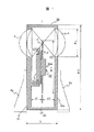
図1は本発明による回転体の騒音防止装置の一実施例を示す一部断面側面図である。
図1に示す回転体の騒音防止装置は、光源、ライトバルブ、回転カラーフィルタ、投写レンズから構成される投写システムに使用して好適な回転カラーフィルタユニットの構造を示している。
図において、回転カラーフィルタユニット1は、回転カラーフィルタ部20と遮音ケース30とから構成されている。回転カラーフィルタ部20はカラーフィルタディスク21とこれを駆動するモータ22とから構成され、モータ22はロータ部22aとステータ部22bとから構成されている。遮音ケース30はカラーフィルタディスク2を取付ける取付けベース31とカバー32から構成されている。カバー32は円筒形の底部に壁を設けた形状をしており以後これを鍋状と言う。32aは鍋状のカバー32の底部又は端壁を示す。また、また、4は第1のコンデンサレンズ、5は第2のコンデンサレンズである。また、6a、6bは遮音ケース30を取り付けるための取付けための支持体である。
【0016】
カラーフィルタディスク21は、例えば直径φ40〜110で厚さt=1.1mmのガラス素材からなる円板状であり、キセノンランプ,メタルハライドランプ,超高圧水銀灯などから発生された白色光をRGB(赤色・緑色・青色)の色波長に分離するためのカラーフィルタ素材がコーティングされたものである。
そして、回転カラーフィルタ部20は、投写される映像の色同期をとるために高速(例えば3600rpm以上)で回転されるために風切り音および振動を生じる。
風切り音は、回転カラーフィルタ部20を密閉した遮音ケース30で覆うか、もしくは図1に示すように密閉した遮音ケース30の中に封鎖することによって遮音することが可能である。また、遮音ケース30の大きさと形状および厚さが遮音の度合いに寄与する。
【0017】
図において、遮音ケース30はカラーフィルタディスク21の直径φDと第1および第2のコンデンサレンズ4、5の直径φLの寸法を足した直径φC(≒φD+φL)を有する円筒状のものであり、円筒部の長さDは第1および第2のコンデンサレンズ4,5の間隔とほぼ等しく構成している。
また筒の両端は取付けベース31とカバー32の端壁32aによって密閉された構成になっている。
その結果、図1において回転カラーフィルタ部20は密閉した遮音ケース30の中に封鎖された状態になり遮音効果は良好である。
カラーフィルタディスク21と取付ける取付けベース31の間隔d1およびカラーフィルタディスク21とカバー32の端壁32aの間隔d2は大きいほうが良いが、コンデンサレンズ4,5の部分が遮音ケース内に突出すると風切り音が増加する原因となるので、前述したように遮音ケース30の円筒部の長さDは第1および第2のコンデンサレンズ4、5の間隔とほぼ等しくすることが適当な構成である。
【0018】
図1において、例えば遮音ケース30の直径φC=136mmは、カラーフィルタディスク21の直径φD=85mmと、第1および第2のコンデンサレンズ4、5の直径φL=45mmを足した寸法にほぼ等しい。
また、カラーフィルタディスク21と、回転カラーフィルタ部20を取付ける取付けベース31の間隔d1をd1=17mmとし、およびカラーフィルタディスク21とカバー32の端壁32aの面の間隔d2を、d2=19mmとし、d1とd2を加算した値に、取付けベース31の厚さ、およびカバー32の端壁32aの厚さを加えた数値は、第1および第2のコンデンサレンズ4、5の間隔L=50とほぼ等しくしている。また、間隔d1および間隔d2は第1および第2のコンデンサレンズ4、5の焦点距離にそれぞれ等しい。
【0019】
カラーフィルタディスク21が回転を始めると遮音ケース30の内部の空気を切るようにカラーフィルタディスク21が回転するために風切り音が生じ、更にモータ22の電磁音による騒音レベルが大きくなるが、やがて遮音ケース30の内部の空気がカラーフィルタディスク21とともに渦流となって回転するようになり騒音レベルが低下し定常状態になる。
この場合、遮音ケース30の内部は出来うる限り平坦にすると良好である。この理由は、渦流の回転とカラーフィルタディスク21の回転が同回転であれば風切り音は発生しない。故に、渦流が高回転で生じ易くするために、遮音ケース30の内部は摩擦が生じないように、構造上および表面仕上げを出来うる限り平坦にする。そして、滑り性が大きいポリフロロカーボンなどの表面円滑剤をコーティングすると、空気の摩擦が少なくなり、騒音をさらに低減できる。
遮音ケース30をアルミニウム合金やマグネシウム合金などで製造した場合、遮音ケース30の厚さは2mm以上が望ましい。厚さが厚いほど遮音効果は高くなる。そして、プラスチック材料の場合は、さらに厚くし充填材(補強材)を混合するとよい。
【0020】
以下に、図2(a)、図2(b)を用いて遮音ケース30のカバー32の詳細について説明する。
図2(a)は本発明による回転体の騒音防止装置に用いて遮音ケースのカバーの一実施例を示す一部断面側面図、図2(b)はその平面図である。
遮音ケース30の軽量化を図るためには、例えば、図2(a)(b)に示すように、遮音ケース30のカバー32の肉厚を薄くし、内面32uを平坦にして外面に補強リブ32rを複数設ける。しかし、遮音ケース30のカバー32の厚さが薄くなると遮音効果は低下するので、外面のリブ32rの間に複数のゴム材32dを充填するように貼付する。これによって遮音効果と制振効果を合せて得られる。
【0021】
次に、図3および図4を用いて遮音ケース30のカバー32部の他の実施例について説明する。
図3及び図4は遮音ケースのカバーの他の実施例を示す断面図である。
カラーフィルタディスク21の回転により渦流が生じることによって、カバー32の端壁32aの面がカラーフィルタディスク21の方へ引込まれるように作用し、カバー32の端壁32aの面が振動する。この作用による振動を抑制するために、図3に示すように、カバー32の端壁32aを内側に湾曲させるか、もしくは図4に示すようにカバー32の端壁32aを外側に湾曲させる。
【0022】
カバー32の端壁32aを図3又は図4に示すように湾曲させることによって、カバー32の端壁を平板にした場合に比べ強度が増し振動が減少する。さらに、図3および図4に示すカバー32においても図2に示したリブ32rとゴム材32dを用いて補強と遮音効果を上げて振動を抑制すると更に効果的である。
遮音ケース30は、例えば図1に合せ示すように、回転カラーフィルタユニット1の両側に支持体6a、6bを取付け、さらにこの支持体6a、6bを投写システムの本体筐体(図示せず)に取付けることによって本体筐体に支持される。
この支持体6a、6bは図1の下方から見た場合、コ字状に形成し、このコ字状の間に本体筐体の取付け部を挿入して取り付けると好適である。また、この支持体6a、6bは遮音ケース30の取付けベース31およびカバー32に一体に成形してもよい。
【0023】
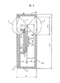
次に図5を用いて、本発明による回転体の騒音防止装置の第2の実施例について、回転カラーフィルタユニット1を用いて説明する。
図5は本発明による回転カラーフィルターユニットの第2の実施例を示す一部断面側面図である。
図は回転カラーフィルタユニット1の回転カラーフィルタ部20を遮音ケース30の取付けベース31に取付ける構造を示している。
一般に、回転カラーフィルタ部20はネジを3本用いて取付けベース31の取付け部31aに直に取付けられ固定されている。そのために、カラーフィルタディスク21が回転することによって生じる風切り音とともに、カラーフィルタディスク2が回転することによって生じる振動が取付けベース31からカバー32に伝導し、取付けベース31およびカバー32が振動し騒音となって放射される。
【0024】
まず、回転カラーフィルタ部20の振動が取付けベース31に伝導しないようにするために、図5に示すように、回転カラーフィルタ部20と取付けベース31、詳しくは取付けベース31の取付け部31aの間に振動を遮断するゴムなどからなる環状(リング状)の緩衝材70を設けて取付けネジ8で固定する。
【0025】
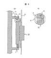
このネジの取り付けについて、図6(a)、図6(b)を用いて説明する。
図6(a)は図5に示す回転カラーフィルタユニットの一部拡大断面図、図6(b)は図6(a)のさらに一部拡大断面図である。
図6(a)、図6(b)に示すように、取付けベース31の取付け部31aと回転カラーフィルタ部20の間に緩衝材70を設けると共に、取付けベース31のネジ8が挿入される部分に振動を遮断するゴムなどからなるブッシング9を介して、ネジ8で取付けベース31と回転カラーフィルタ部20を取付けると、ネジ8が直接取付けベース31に接しないため、効果的に遮音することができる。
【0026】
しかし、複数のネジ8(本実施例では3本)を用いた場合は、ネジ絞めのバラツキによって緩衝材70の効果が半減し、さらには回転カラーフィルタ部20が傾きカラーフィルタの効果が落ちることもある。
【0027】
そこで、図7を用いて説明するようにネジ8を1本用いた構造にすると更に遮音効果を上げることができる。
図7は本発明による回転カラーフィルタユニットの第3の実施例を示す一部拡大断面側面図である。
図7に示すように回転カラーフィルタ部20のモータ22のステータ部22bの中心部を1本のネジ8aで取付けベース31に固定する。この場合、ネジ8aは図5(b)に示したように取付けベース31の間にゴムなどからなるブッシング9aを介して取付け固定する。図5に示した、回転カラーフィルタ部20の固定方法に比べ、この図7に示した固定方法の方が騒音レベルをさらに5dB以上低減することができる。
【0028】
図5又は図7に用いた緩衝材70をゴム材で構成した場合、材質は、ブチルゴムを基材とした制動効果の高い材料が良い。実施例では緩衝材70の厚さは1〜3mmとし、硬度Hsは20〜60度のものを用いた。硬度Hsは低いほど振動の遮断効果がある。硬度Hsが低い場合は緩衝材70の厚さtを薄く、硬度Hsが高い場合は緩衝材70の厚さを厚くすることができる。
しかし、硬度Hs=20度以下にすると経時変化が大きくなり、ネジ8、8aで締付け固定した後に回転カラーフィルタ部20の自重によって変形し易い欠点が生じることがある。
また、緩衝材70の材料としてはポリオレフィン系のプラスチックの発泡体を用いても同様な効果が得られる。
図5及び図7で用いた緩衝材70の形状は真ん中に穴を設けた環状であるが、図8に示す形状にすると更に効果を高めることができる。
【0029】
図8(a)、(b)はそれぞれ本発明による回転カラーフィルタユニットに使用する緩衝材の一実施例を示す断面側面図及び平面図である。図9(a)、(b)はそれぞれ本発明による回転カラーフィルタユニットに使用する緩衝材の他の実施例を示す断面側面図及び平面図である。
図8(a)、(b)において、緩衝材71は環状に構成されると共に、表面に複数の凸部71aが設けられている。このため、緩衝材71の全面が取付けベース31または回転カラーフィルタ部20に接しないため、硬度Hsを高くしても遮音効果を得ることができる。
【0030】
凸部71aや鍔部72aが設けられていない環状の緩衝材70は、平板の材料を打抜き型で打抜いて構成するためコストが安いが、この形状ではカラーフィルタディスク21を駆動するモータ22のステータ部22bの端面が取付けベース31に接することがあった。そこで、図9(a)、(b)に示すように、環状の緩衝材72の周辺に鍔部72aを設け、回転カラーフィルタ部20のモータ22のステータ部22bを包み込むように取付けベース31に取付けることによって振動を遮断する効果をさらに上げることができる。
図5に示した第2の実施例の構成では各部の大きさによって、回転カラーフィルタ部20のモータ22を取付ける取付けベース31の一部が光路Pを遮ることがあった。この点を改良した回転カラーフィルタユニットを図10を用いて説明する。
【0031】
図10は本発明による回転カラーフィルタユニットの第4の実施例を示す一部断面側面図である。
図10に示す第3の実施例では、回転カラーフィルタ部20のモータ22のステータ部22bを取付ける取付けベース31の一部を別部品として構成する。この別部品はステータ部22bを直接取り付ける取付け部31bを構成する。更に、この取り付け部31bは取付けベース31と接する部分を狭く、ステータ部22bに接する部分を広くした台形状に形成されている。また、取付け部31bは取付けベース31に嵌合され複数のネジ8bで固定されている。
【0032】
回転カラーフィルタ部20のモータ22は、緩衝材70を介して取付けベース31の取付け部31bに接し、さらにモータ22のステータ部22bをブッシング9を介してネジ8で直接に取付けベース31の取付け部31b取付けられる。
したがって、モータ22は取付け部31bに接しないようにネジ8で固定される。
この場合、ネジ8はネジの締付けトルクを設定してネジ絞め固定するが、緩衝材70およびブッシング9のゴム硬度Hsのバラツキによって緩衝材70およびブッシング9の圧縮が安定せず、回転カラーフィルタ部20のモータ22の振動が取付けベース31の取付け部31bに伝達されることがあった。
【0033】
これを避けるには、ネジ8の長さを適宜選択してネジ8が回転カラーフィルタ部20のモータ22のステータ部22bに設けたネジ穴の底部に衝突させそれ以上にネジ8が回らないようにする。これによって、緩衝材70およびブッシング9がネジ8を締付けることによって一定以上に圧縮されることがないので、緩衝材としての効果が安定する。
【0034】
また、取付けベース31の取付け部31bと回転カラーフィルタ部20と緩衝材70とブッシング9とネジ8を予め組立てたサブアッセンブリーとし、取付けベース31の取付け部31bの一部分に加速度センサーを取付け、予め振動の様子を予備検査することによって性能を一定レベルに保持することが可能となる。
なお、図10に示す第4の実施例では、コンデンサレンズ4および5は遮音ケース30の下部に設けた例を示している。
【0035】
次に、図11を用いて、本発明の第5の実施例について説明する。
図11は本発明による回転カラーフィルタユニットの第5の実施例を示す一部断面側面図である。今まで説明した第1から第4の実施例において、回転カラーフィルタ部20のモータ22としては偏平状の薄形モータが用いられている。そのために外径が大きく、図1および図5に示す実施例の構造では、各部の寸法の取り方によっては、取付けベース31の一部が第1のコンデンサレンズ4で収束され第2のコンデンサレンズ5に至る光路Pを遮ることがあった。
そこで、図11に示す実施例では外径が小さく、奥行きのある形状のモータ23が用いられている。このモータ23はロータ部23aとステータ部23bから構成されている。
【0036】
モータ23のステータ部23bは遮音ケース30の取付けベース31にディスク状の緩衝材71を介して接触させ、取付けベース31の穴にプッシング9を装着し、ネジ8を用いて回転カラーフィルタ部20を取付けベース31に固定している。これによって、回転カラーフィルタ部20のモータ23の取付け部が光路を遮ることなくなり、さらに回転カラーフィルタ部20のモータ23の取付けが簡素化できた。なお、図11に示す第3の実施例において、緩衝材70の形状はディスク状に構成されている。
【0037】
次に、図12を用いて本発明の第6の実施例について説明する。
図12は本発明による回転カラーフィルタユニットの第5の実施例を示す一部断面側面図である。
図12に示す第6の実施例では、遮音ケース30の形状をコンパクトにし、かつ回転カラーフィルタ部20の振動によって遮音ケース30内で発生する騒音の特異のスペクトルを吸音構造によって吸音し、騒音レペルを低減する構造を示している。
【0038】
図1に示した遮音ケース30の奥行き寸法Dは第1および第2のコンデンサレンズ4、5の間隔と等しくしている。そのために、回転カラーフィルタユニット1を投写システムの本体筐体に取付けるための支持体6a、6bが両側に設けられているために、他の部品を取付けるための障害となっている。
そこで、図12に示すように、第1および第2のコンデンサレンズ4、5に鏡筒10a、10bを設ける構造とし、遮音ケース30の奥行き寸法D’を短くして鏡筒10a,10bの下部に回転カラーフィルタユニット1を投写システムの本体筐体に取付けるための支持体6a、6bを配置するように構成している。
【0039】
しかし、鏡筒10a、10bを設けたことよって、遮音ケース30の取付けベース31およびカバー32のそれぞれの面に平坦でない部分が形成されるため風切り音が増加する。
【0040】
遮音ケースの奥行き寸法D’は第1または第2のコンデンサレンズ4、5の間隔寸法の約4分の3から3分の1とした。そのため、鏡筒10a、10bが長くなり、且つカラーフィルタディスク21と遮音ケース30との間隔d1およびd2が狭くなったことが相挨まって特異のスペクトルが増加し騒音レベルが大きくなることがあった。
その場合は、鏡筒10a、10bの空洞部の容積を利用してヘルムホルツレゾネータ11a、11bを形成し、特異のスペクトルを吸音し騒音レベルを低下させることができる。
【0041】
図13はヘルムホルツレゾネータの原理を説明するための模式図である。
図において、11はヘルムホルツレゾネータであり、容積V、開口部の直径d開口部の板圧tを持っている。
このヘルムホルツレゾネータ11の共鳴周波数frの計算式は、以下に示す通りである。
【0042】
【数1】

ここで、 C:音速
d:孔の直径
t:孔の厚さ
V:レゾネータの体積
また、それぞれの鏡筒10a、10bで形成されるヘルムホルツレゾネータ11a、11bは、孔の直径d、孔の厚さt、レゾネータの体積Vの条件を変えて異なった2つのスペクトルの周波数frに設定する。
その結果、騒音の原因となる異なった2つのスペクトルを吸音することが可能となり騒音レベルを低下させることができる。
【0044】
図14(a)、(b)はヘルムホルツレゾネータの2つの共鳴周波数の間隔を変えた場合の特性図である。図において、横軸は周波数fを、縦軸は振幅Aを示す。
図14(a)では2つの共鳴周波数fr1,fr2による総合周波数特性が略平坦になるように共鳴周波数fr1,fr2間を定めた場合を示し、図14(b)は総合の周波数特性において、振幅が大きくなるように2つの共鳴周波数fr1,fr2の間隔を定めた場合を示す。このように、2つの周波数fr1,fr2の間隔を設定することにより、共鳴周波数frの見かけの帯域を広く、または共鳴峰を高くすることが可能である。
【0045】
同様にして、本実施例を用いることによって、騒音の原因となる周波数変動のある、もしくは大きいレベルの特異のスペクトルを吸音することが可能となり騒音レベルを低下させることができる。
回転体の騒音防止装置の実施例として、回転カラーフィルタユニットについて述べたが、本発明による回転体の騒音防止装置においては、回転体はカラーフィルタに限定されることなく、いかなる回転体の騒音防止にも有用である。
【0046】
以上述べたように、本発明による回転体の騒音防止装置においては、回転体を駆動するモータによって生じる振動を、遮音ケースの取付けベースに伝導しないように緩衝材を介して取付けている。例えば、回転カラーフィルタユニットの回転カラーフィルタ部のカラーフィルタディスクを駆動するモータによって生じる振動を、遮音ケースの取付けベースに伝導しないように緩衝材を介して取付けている。
【0047】
その結果、回転体、又は回転カラーフィルタ部を駆動するモータが回転することによって生じる振動は取付けベースおよびカバーに伝導しなくなり、かつ、回転体部(回転体とモータ)又は回転カラーフィルタ部全体を遮音ケースで覆うか、もしくは封じ込めるように構成したことと相挨って、回転体部または回転カラーフィルタユニットの騒音を大幅に低減することができる。
【0048】
また、回転体、又はカラーフィルタディスクと取付けベースの間隔、および回転体、又はカラーフィルタディスクと遮音ケースのカバーの端壁の間隔を加えた間隔を十分に取っている。回転カラーフィルタユニットの場合は、第1および第2のコンデンサレンズの間隔とほぼ等しくなるように充分に取っている。
【0049】
さらには、遮音ケースのカバーの内面を平滑にしている。その結果、遮音カバーの中で回転体、又はカラーフィルタディスクが回転することによって生じる渦流の流れがスムーズになり、回転体、又はカラーフィルタディスクが回転することによって生じる風切り音が減少し、遮音ケースを透過する騒音を低減することができる。
【0050】
さらに、回転カラーフィルタユニットにおいては、遮音ケースに2つの鏡筒を付随させ、これら鏡筒によって形成された空間部にヘルムホルツレゾネータを構成し、カラーフィルタディスクが回転することによって遮音ケースに生じる騒音の特異なスペクトルを吸音し騒音レベルを低減することができる。
【0051】
【発明の効果】
以上述べたように、本発明によれば、回転体及びそれを駆動するモータによって生じる騒音を低減することができる。
【図面の簡単な説明】
【図1】本発明による回転体の騒音防止装置の一実施例を示す一部断面側面図である。
【図2】本発明による回転体の騒音防止装置に用いて遮音ケースのカバーの一実施例を示す一部断面側面図及びはその平面図である。
【図3】遮音ケースのカバーの他の実施例を示す断面図である。
【図4】遮音ケースのカバーの更に他の実施例を示す断面図である。
【図5】本発明による回転カラーフィルターユニットの第2の実施例を示す一部断面側面図である。
【図6】図5に示す回転カラーフィルタユニットの一部拡大断面図である。
【図7】本発明による回転カラーフィルタユニットの第3の実施例を示す一部拡大断面側面図である。
【図8】本発明による回転カラーフィルタユニットに使用する緩衝材の一実施例を示す断面側面図及び平面図である。
【図9】本発明による回転カラーフィルタユニットに使用する緩衝材の他の実施例を示す断面側面図及び平面図である。
【図10】本発明による回転カラーフィルタユニットの第4の実施例を示す一部断面側面図である。
【図11】本発明による回転カラーフィルタユニットの第5の実施例を示す一部断面側面図である。
【図12】本発明による回転カラーフィルタユニットの第5の実施例を示す一部断面側面図である。
【図13】ヘルムホルツレゾネータの原理を説明するための模式図である。
【図14】ヘルムホルツレゾネータの2つの共鳴周波数の間隔を変えた場合の特性図である。
【図15】投写システムの模式図である。
【符号の説明】
1…回転カラーフィルタユニット、20…回転カラーフィルタ部、21…カラーフィルタディスク、22…回転カラーフィルタを駆動するモータ、22a…ロータ部、22b…ステータ部、30…遮音ケース、31…取付けベース、32…カバー、32a…カバー32の端壁、32r…カバー32の補強リブ、32d…ゴム材、4…第1のコンデンサレンズ、5…第2のコンデンサレンズ、6a、6b…支持体、70、72…緩衝材、71a…凸部、72a…鍔部、8…ネジ、9…ブッシング、10a、10b…鏡筒、11…ヘルムホルツレゾネータ、51…投写型システム、52…キセノンランプ、53…第1のコンデンサレンズ、54…回転カラーフィルタ、55…第2のコンデンサレンズ、56…マイクロミラーデバイス、57…投写レンズ、58…スクリーン。[0001]
BACKGROUND OF THE INVENTION
The present invention relates to a rotating body noise prevention device or a rotating body noise prevention technique, and is particularly suitable for application to a rotating color filter unit subjected to noise prevention treatment and a projection system using the same.
[0002]
[Prior art]
A projection system having a rotating color filter unit is disclosed in, for example, the literature (White Enhancement for Color Sequential DLP: Society for Information Display International Symposium 2: Preprint p 121-124: My Print 121-124: My Print). Such a projection system uses a micromirror device and a rotating color filter, and has a principle diagram as shown in FIG.
[0003]
FIG. 15 is a schematic diagram of a projection system. In the figure, the light emitted from the
[0004]
In this
The rotating
[0005]
[Problems to be solved by the invention]
The rotating
[0006]
The objective of this invention is providing the technique which prevents the noise of a rotary body.
[0007]
[Means for Solving the Problems]
According to the present invention. In order to isolate wind noise, the rotating color filter part is covered or confined with a sealed sound insulation case. Furthermore, if the vibration of the motor that drives the rotating color filter part is transmitted to the sound insulation case, the sound insulating case vibrates and generates noise, so that the vibration of the motor that drives the rotating color filter part is not conducted to the sound insulation case.
In order to achieve an object of the present invention, in the first invention, a noise prevention device for a rotating body includes a rotating body portion including a rotating body and a motor that drives the rotating body, a mounting base to which the rotating body portion is attached, And a cover arranged to cover the rotating body portion attached to the attachment base.
[0008]
According to a second aspect of the present invention, a noise preventing device for a rotating body is provided between a rotating body portion comprising a rotating body and a motor for driving the rotating body, an attachment base to which the rotating body portion is attached, and the rotating body portion and the attachment base. And a cover disposed to cover the rotating body portion attached to the attachment base.
[0009]
In the first or second invention, the sound insulation case including the mounting base and the cover is sealed. In addition, the motor includes a rotor portion that rotates a rotating body and a stator portion that is attached to the attachment base. In the present invention, a cushioning material is provided between the mounting base and the stator portion of the motor, and the mounting base and the stator portion are screwed via a bushing that blocks vibration. In addition, a cushioning material is provided between the mounting base and the stator portion of the motor, and the stator portion is fitted to the mounting portion of the mounting base so as to block vibration between the mounting base and the center of the stator portion. Screw through the bushing.
[0010]
In the first or second invention, the cover is configured in a pan shape, a reinforcing rib is provided on the outer side of the bottom portion, and a sound insulating material is attached between the ribs. Moreover, the said cover is comprised in a pan shape, and the bottom part is curved in any one of an inner side and an outer side.
[0011]
In the second invention, the material of the buffer material is butyl rubber and has a hardness Hs of 20 to 60 degrees. The cushioning material is a polyolefin plastic foam. Moreover, the said buffer material is comprised cyclically | annularly and provides a convex part in the surface. Still further, the cushioning material is formed in an annular shape, and a collar portion is provided on the annular peripheral portion. An apparatus for preventing noise of a rotating body.
[0012]
In the third invention, the rotating color filter unit covers a rotating color filter unit including a color filter disk and a motor for rotating the color filter disk, a mounting base for mounting the rotating color filter unit, and the rotating color filter unit. And a sound insulation case made of a cover.
In the third invention, the sound insulation case is hermetically sealed. The motor includes a rotor portion and a stator portion, and the stator portion and the mounting base are attached with screws via a buffer material that blocks vibration between the stator portion of the motor and the mounting base. The material of the buffer material is butyl rubber and has a hardness Hs of 20 to 60 degrees. The cushioning material is a polyolefin plastic foam. Moreover, a convex part is provided on the surface of the cushioning material. Moreover, the said buffer material is comprised cyclically | annularly and provides a collar part around the said cyclic | annular form. The cushioning material is disc-shaped. Further, it is preferable that the stator portion of the motor is fitted to the mounting base via a cushioning material and fixed with a screw via a rubber bushing that blocks vibration. It is preferable that the mounting base and the stator center be fixed with one screw through a rubber bushing that blocks vibration.
[0013]
In the third aspect of the invention, the first and second condenser lenses are provided in the sound insulation case, and the diameter of the sound insulation case is approximately equal to the size of the diameter of the color filter disk and the diameter of the first or second condenser lens. Make equal. In addition, a first condenser lens is provided on the mounting base, a second condenser lens is provided on the cover, the first condenser lens and the second condenser lens are arranged to face each other, and the depth dimension of the sound insulation case is determined. Is approximately equal to the distance between the first condenser lens and the second condenser lens.
3rd invention WHEREIN: The shape of the said cover of the said sound insulation case is made into a pan shape, and the said pot-shaped bottom part is curved to one of an outer side and an inner side. Moreover, the shape of the cover of the sound insulation case is made into a pan shape, a reinforcing rib is provided, and a rubber material is pasted between the reinforcing ribs. In addition, the sound insulation case is provided with first and second lens barrels, a first condenser lens and a second condenser lens are arranged in each of the lens barrels, and the depth dimension of the sound insulation case is set to the first condenser lens. And approximately 1/2 to 1/3 of the interval between the second condenser lenses. Helmholtz resonators are formed in the first lens barrel and the second lens barrel. The two Helmholtz resonators set the resonance frequency of the Helmholtz resonator to adjacent frequencies. The two Helmholtz resonators are configured such that the resonance frequency of the Helmholtz resonator is set to a separate frequency that is not adjacent.
[0014]
In a fourth aspect of the invention, the projection system covers a rotating color filter section comprising a light source, a color filter disk and a motor for rotating the color filter disk, a mounting base for mounting the rotating color filter section, and the rotating color filter section. The rotary color filter unit includes a sound insulation case made up of a cover, a light valve, and a projection lens.
In a fourth invention, the sound insulation case is hermetically sealed, and the motor is composed of a rotor part and a stator part, and the stator part is interposed between the stator part and the mounting base via a cushioning material. The mounting base is attached by screws.
[0015]
DETAILED DESCRIPTION OF THE INVENTION
Hereinafter, embodiments of the present invention will be described with reference to the drawings using some examples.
FIG. 1 is a partially sectional side view showing an embodiment of a noise prevention device for a rotating body according to the present invention.
The rotating body noise prevention apparatus shown in FIG. 1 shows a structure of a rotating color filter unit suitable for use in a projection system including a light source, a light valve, a rotating color filter, and a projection lens.
In the figure, the rotating
[0016]
The
The rotating
The wind noise can be sound-insulated by covering the rotating
[0017]
In the figure, the
Further, both ends of the cylinder are sealed by the mounting
As a result, in FIG. 1, the rotary
The distance d1 between the
[0018]
In FIG. 1, for example, the diameter φC = 136 mm of the
Further, the distance d1 between the
[0019]
When the
In this case, it is preferable to make the inside of the
When the
[0020]
Below, the detail of the
FIG. 2A is a partially sectional side view showing an embodiment of a cover of a sound insulation case used in the noise prevention device for a rotating body according to the present invention, and FIG. 2B is a plan view thereof.
In order to reduce the weight of the
[0021]
Next, another embodiment of the
3 and 4 are sectional views showing other embodiments of the cover of the sound insulation case.
The rotation of the
[0022]
By curving the
In the
The
[0023]
Next, a second embodiment of the noise prevention device for a rotating body according to the present invention will be described using the rotating
FIG. 5 is a partially sectional side view showing a second embodiment of the rotating color filter unit according to the present invention.
The figure shows a structure in which the rotary
In general, the rotary
[0024]
First, in order to prevent vibration of the rotating
[0025]
The attachment of the screw will be described with reference to FIGS. 6 (a) and 6 (b).
6A is a partially enlarged sectional view of the rotating color filter unit shown in FIG. 5, and FIG. 6B is a further partially enlarged sectional view of FIG. 6A.
As shown in FIGS. 6A and 6B, a
[0026]
However, when a plurality of screws 8 (three in this embodiment) are used, the effect of the
[0027]
Therefore, as described with reference to FIG. 7, a sound insulation effect can be further improved by using a structure using one
FIG. 7 is a partially enlarged sectional side view showing a third embodiment of the rotating color filter unit according to the present invention.
As shown in FIG. 7, the central portion of the stator portion 22b of the
[0028]
When the
However, when the hardness is Hs = 20 degrees or less, the change with time increases, and there is a case where a defect that is easily deformed by the weight of the rotating
Further, the same effect can be obtained even if a polyolefin plastic foam is used as the material of the
The shape of the
[0029]
FIGS. 8A and 8B are a sectional side view and a plan view, respectively, showing an embodiment of a cushioning material used in the rotating color filter unit according to the present invention. FIGS. 9A and 9B are a sectional side view and a plan view, respectively, showing another embodiment of the cushioning material used in the rotating color filter unit according to the present invention.
8A and 8B, the cushioning
[0030]
The
In the configuration of the second embodiment shown in FIG. 5, a part of the mounting
[0031]
FIG. 10 is a partially sectional side view showing a fourth embodiment of the rotating color filter unit according to the present invention.
In the third embodiment shown in FIG. 10, a part of the mounting
[0032]
The
Therefore, the
In this case, the
[0033]
In order to avoid this, the length of the
[0034]
In addition, the mounting
In the fourth embodiment shown in FIG. 10, the
[0035]
Next, a fifth embodiment of the present invention will be described with reference to FIG.
FIG. 11 is a partially sectional side view showing a fifth embodiment of the rotating color filter unit according to the present invention. In the first to fourth embodiments described so far, a flat thin motor is used as the
Therefore, in the embodiment shown in FIG. 11, a
[0036]
The stator portion 23 b of the
[0037]
Next, a sixth embodiment of the present invention will be described with reference to FIG.
FIG. 12 is a partially sectional side view showing a fifth embodiment of the rotating color filter unit according to the present invention.
In the sixth embodiment shown in FIG. 12, the shape of the
[0038]
The depth dimension D of the
Therefore, as shown in FIG. 12, the first and
[0039]
However, by providing the lens barrels 10a and 10b, wind noise is increased because uneven portions are formed on the respective surfaces of the mounting
[0040]
The depth dimension D ′ of the sound insulation case is set to about three-quarters to one-third of the distance between the first or
In that case, the
[0041]
FIG. 13 is a schematic diagram for explaining the principle of the Helmholtz resonator.
In the figure, 11 is a Helmholtz resonator having a volume V and a diameter d of the opening d and a plate pressure t of the opening.
The resonance frequency f of this Helmholtz resonator 11 r The calculation formula is as follows.
[0042]
[Expression 1]
Where C: speed of sound
d: Diameter of the hole
t: thickness of hole
V: Volume of the resonator
Further, the
As a result, two different spectra that cause noise can be absorbed, and the noise level can be reduced.
[0044]
FIGS. 14A and 14B are characteristic diagrams when the interval between two resonance frequencies of the Helmholtz resonator is changed. In the figure, the horizontal axis represents the frequency f, and the vertical axis represents the amplitude A.
In FIG. 14 (a), the two resonance frequencies f r1, f r2 The resonance frequency f so that the overall frequency characteristic due to becomes substantially flat. r1, f r2 FIG. 14B shows two resonance frequencies f so that the amplitude becomes large in the overall frequency characteristic. r1, f r2 The case where the interval of is defined is shown. Thus, the two frequencies f r1, f r2 By setting the interval of the resonance frequency f r It is possible to widen the apparent band of or increase the resonance peak.
[0045]
Similarly, by using this embodiment, it is possible to absorb a specific spectrum having a frequency variation or a large level that causes noise, and the noise level can be reduced.
The rotary color filter unit has been described as an example of the noise prevention device for the rotating body. However, in the noise prevention device for the rotating body according to the present invention, the rotating body is not limited to the color filter, and any noise prevention of the rotating body is possible. Also useful.
[0046]
As described above, in the noise prevention device for a rotating body according to the present invention, the vibration generated by the motor that drives the rotating body is attached via the cushioning material so as not to be transmitted to the mounting base of the sound insulation case. For example, the vibration generated by the motor that drives the color filter disk of the rotary color filter unit of the rotary color filter unit is attached via a cushioning material so as not to be conducted to the mounting base of the sound insulation case.
[0047]
As a result, the vibration generated by the rotation of the rotating body or the motor driving the rotating color filter section is not conducted to the mounting base and the cover, and the rotating body section (rotating body and motor) or the entire rotating color filter section is removed. The noise of the rotating body part or the rotating color filter unit can be greatly reduced due to the fact that it is configured so as to be covered or enclosed with a sound insulating case.
[0048]
In addition, a sufficient interval is taken, including the distance between the rotating body or the color filter disk and the mounting base, and the distance between the rotating body or the color filter disk and the end wall of the cover of the sound insulation case. In the case of the rotating color filter unit, it is sufficiently set to be substantially equal to the distance between the first and second condenser lenses.
[0049]
Furthermore, the inner surface of the cover of the sound insulation case is smoothed. As a result, the flow of the eddy current generated by the rotation of the rotating body or the color filter disk in the sound insulating cover becomes smooth, and the wind noise generated by the rotation of the rotating body or the color filter disk is reduced. The noise that permeates can be reduced.
[0050]
Further, in the rotating color filter unit, two lens barrels are attached to the sound insulation case, a Helmholtz resonator is configured in a space formed by these lens barrels, and noise generated in the sound insulation case due to the rotation of the color filter disk. It can absorb a unique spectrum and reduce the noise level.
[0051]
【The invention's effect】
As described above, according to the present invention, noise generated by the rotating body and the motor that drives the rotating body can be reduced.
[Brief description of the drawings]
FIG. 1 is a partially sectional side view showing an embodiment of a noise prevention device for a rotating body according to the present invention.
FIGS. 2A and 2B are a partial cross-sectional side view and a plan view showing an embodiment of a cover of a sound insulation case used in a noise prevention device for a rotating body according to the present invention. FIGS.
FIG. 3 is a cross-sectional view showing another embodiment of the cover of the sound insulation case.
FIG. 4 is a cross-sectional view showing still another embodiment of the cover of the sound insulation case.
FIG. 5 is a partial cross-sectional side view showing a second embodiment of the rotating color filter unit according to the present invention.
6 is a partially enlarged cross-sectional view of the rotating color filter unit shown in FIG.
FIG. 7 is a partially enlarged sectional side view showing a third embodiment of the rotating color filter unit according to the present invention.
FIGS. 8A and 8B are a sectional side view and a plan view showing an embodiment of a cushioning material used in the rotating color filter unit according to the present invention. FIGS.
FIGS. 9A and 9B are a sectional side view and a plan view showing another embodiment of the cushioning material used in the rotating color filter unit according to the present invention. FIGS.
FIG. 10 is a partial sectional side view showing a fourth embodiment of the rotating color filter unit according to the present invention.
FIG. 11 is a partial sectional side view showing a fifth embodiment of the rotating color filter unit according to the present invention.
FIG. 12 is a partial cross-sectional side view showing a fifth embodiment of the rotating color filter unit according to the present invention.
FIG. 13 is a schematic diagram for explaining the principle of a Helmholtz resonator.
FIG. 14 is a characteristic diagram when the interval between two resonance frequencies of the Helmholtz resonator is changed.
FIG. 15 is a schematic diagram of a projection system.
[Explanation of symbols]
DESCRIPTION OF
Claims (10)
該回転カラーフィルタ部の該モータが取付けられる取付けベースと、
該回転カラーフィルタ部の全体を覆うカバーと
を備え、
前記回転カラーフィルタ部が、前記取付けベースと前記カバーから構成される密閉された空間内に配されることを特徴とする回転カラーフィルタユニット。A rotating color filter unit having a color filter disk and a motor for rotating the color filter disk;
A mounting base to which the motor of the rotary color filter unit is attached,
A cover covering the entire rotating color filter section ;
With
The rotating color filter unit, wherein the rotating color filter unit is disposed in a sealed space constituted by the mounting base and the cover .
前記モータはロータ部とステータ部とから成り、該ステータ部と前記取付けベースの間に振動を遮断する緩衝材を設けたことを特徴とする回転カラーフィルタユニット。The rotating color filter unit according to claim 1,
The motor comprises a rotor portion and a stator portion, and a rotating color filter unit provided with a buffer material for blocking vibration between the stator portion and the mounting base.
前記緩衝材の表面に凸部を設けたことを特徴とする回転カラーフィルタユニット。The rotating color filter unit according to claim 2,
A rotating color filter unit, wherein a convex portion is provided on the surface of the cushioning material.
前記緩衝材は環状またはディスク状に構成されていることを特徴とする回転カラーフィルタユニット。The rotating color filter unit according to claim 2,
Rotary color filter Yoo two Tsu preparative said buffer material, characterized in that it is configured in annular or disk.
前記カバーの形状を鍋状とし、該鍋状の底部を外側または内側に湾曲させることを特徴とする回転カラーフィルタユニット。The rotating color filter unit according to claim 1,
Rotary color filter unit, characterized in that bending the shape of the cover and the pot-shaped, the該鍋shaped bottom outside or inside.
前記カバーの形状を鍋状とし、該カバーの外面に複数の補強リブを設けるとともに、該複数の補強リブの間にゴム材を設けたことを特徴とする回転カラーフィルタユニット。The rotating color filter unit according to claim 1,
Rotary color filter unit the shape of the cover and the pot-shaped, provided with a plurality of reinforcing ribs on the outer surface of the cover, characterized in that a rubber material between said plurality of reinforcing ribs.
前記カバーに第1の鏡筒を設け、前記取付けベースに第2の鏡筒を設け、該第1の鏡筒に第1のコンデンサレンズを配置し、該第2の鏡筒に第2のコンデンサレンズを配置したことを特徴とする回転カラーフィルタユニット。The rotating color filter unit according to claim 1,
A first lens barrel is provided on the cover, a second lens barrel is provided on the mounting base, a first condenser lens is disposed on the first lens barrel, and a second condenser is provided on the second lens barrel . A rotating color filter unit having a lens arranged.
前記第1の鏡筒と前記第2の鏡筒の部分にヘルムホルツレゾネータが構成されることを特徴とする回転カラーフィルタユニット。The rotating color filter unit according to claim 7,
A rotating color filter unit, wherein a Helmholtz resonator is formed in the first lens barrel and the second lens barrel.
カラーフィルタディスクと該カラーフィルタディスクを回転させるモータとを有して成る回転カラーフィルタ部と、該回転カラーフィルタ部の該モータを取付ける取付けベースと、該回転カラーフィルタ部の全体を覆うカバーとを備え、前記回転カラーフィルタ部が、前記取付けベースと前記カバーから構成される密閉された空間内に配された回転カラーフィルタユニットと、
ライトバルブと、
投写レンズと
を備えて構成されることを特徴とする投写システム。A light source;
A rotary color filter unit comprising a motor for rotating the color filter disc and the color filter disk, a mounting base for mounting the motor of the rotary color filter portion, and a cover for covering the whole of the rotary color filter portion A rotating color filter unit disposed in a sealed space composed of the mounting base and the cover ;
A light valve,
A projection system comprising a projection lens.
前記モータはロータ部とステータ部とから成り、該ステータ部と前記取付けベースの間に振動を遮断する緩衝材を設けたことを特徴とする投写システム。The projection system according to claim 9, wherein
The projection system according to claim 1, wherein the motor includes a rotor portion and a stator portion, and a buffer material that blocks vibration is provided between the stator portion and the mounting base.
Priority Applications (1)
| Application Number | Priority Date | Filing Date | Title |
|---|---|---|---|
| JP27334799A JP4022344B2 (en) | 1999-09-27 | 1999-09-27 | Rotating color filter unit and projection system using the same |
Applications Claiming Priority (1)
| Application Number | Priority Date | Filing Date | Title |
|---|---|---|---|
| JP27334799A JP4022344B2 (en) | 1999-09-27 | 1999-09-27 | Rotating color filter unit and projection system using the same |
Publications (3)
| Publication Number | Publication Date |
|---|---|
| JP2001100309A JP2001100309A (en) | 2001-04-13 |
| JP2001100309A5 JP2001100309A5 (en) | 2005-01-06 |
| JP4022344B2 true JP4022344B2 (en) | 2007-12-19 |
Family
ID=17526640
Family Applications (1)
| Application Number | Title | Priority Date | Filing Date |
|---|---|---|---|
| JP27334799A Expired - Lifetime JP4022344B2 (en) | 1999-09-27 | 1999-09-27 | Rotating color filter unit and projection system using the same |
Country Status (1)
| Country | Link |
|---|---|
| JP (1) | JP4022344B2 (en) |
Families Citing this family (9)
| Publication number | Priority date | Publication date | Assignee | Title |
|---|---|---|---|---|
| JP4590707B2 (en) * | 2000-09-13 | 2010-12-01 | パナソニック株式会社 | Color sequential color display device |
| CN108646508B (en) * | 2012-12-20 | 2021-06-08 | 深圳光峰科技股份有限公司 | Light emitting device and related projection system |
| JP6222547B2 (en) * | 2013-06-25 | 2017-11-01 | 株式会社リコー | Illumination device and image projection device |
| JP6394076B2 (en) * | 2014-06-04 | 2018-09-26 | セイコーエプソン株式会社 | Light source device and projector |
| US9851075B2 (en) | 2014-07-03 | 2017-12-26 | Sony Corporation | Phosphor wheel, light source unit, and image display device |
| JP6617274B2 (en) * | 2014-09-17 | 2019-12-11 | パナソニックIpマネジメント株式会社 | Phosphor wheel device, phosphor wheel device housing, and projection-type image display device |
| JP6638419B2 (en) * | 2016-01-20 | 2020-01-29 | セイコーエプソン株式会社 | Light source device and projector |
| CN107087098B (en) * | 2017-07-03 | 2023-06-27 | 深圳天珑无线科技有限公司 | Camera and camera device |
| JP7070146B2 (en) * | 2018-06-25 | 2022-05-18 | 株式会社リコー | Light source module and optical device |
-
1999
- 1999-09-27 JP JP27334799A patent/JP4022344B2/en not_active Expired - Lifetime
Also Published As
| Publication number | Publication date |
|---|---|
| JP2001100309A (en) | 2001-04-13 |
Similar Documents
| Publication | Publication Date | Title |
|---|---|---|
| JP4022344B2 (en) | Rotating color filter unit and projection system using the same | |
| JP6986365B2 (en) | In-vehicle speaker system | |
| US5818622A (en) | Optical scanning apparatus | |
| US20060050346A1 (en) | Noise-reducing resonator and laser-scanning unit with the same | |
| CN1665285A (en) | Device for reducing deteriroation of image quality in display using laser | |
| JP2008190434A (en) | Fan retention structure and electronic apparatus | |
| US20020114484A1 (en) | Compact narrow band loudspeaker enclosure | |
| JP2001100309A5 (en) | ||
| JP2006323117A (en) | Color wheel device, projector, and method for manufacturing color wheel device | |
| JPS6349725A (en) | Rotary polygon mirror fitting device for scanner | |
| JPS58124057A (en) | Suction air resonator | |
| JPH0979199A (en) | Motor-driven air blower | |
| JP4083972B2 (en) | Drive device storage case | |
| JP7006116B2 (en) | Sound absorbers and projectors | |
| WO2014045364A1 (en) | Vibrating body mounting structure and projection-type image display device provided with same | |
| JPS6319012Y2 (en) | ||
| JP3099644B2 (en) | Pulley mechanism | |
| JPH05341221A (en) | Optical scanner | |
| JP2002369450A (en) | Electrical appliance | |
| JP2583737B2 (en) | Piston power machine or work machine | |
| JPS6143616Y2 (en) | ||
| JPS5916547Y2 (en) | Hermetic electric compressor | |
| JP2003139095A (en) | Casing | |
| KR20040023430A (en) | Structure for reducing noise of hermetic compressor | |
| JPH11346395A (en) | Passive radiator |
Legal Events
| Date | Code | Title | Description |
|---|---|---|---|
| A977 | Report on retrieval |
Free format text: JAPANESE INTERMEDIATE CODE: A971007 Effective date: 20051031 |
|
| A131 | Notification of reasons for refusal |
Free format text: JAPANESE INTERMEDIATE CODE: A131 Effective date: 20070424 |
|
| A521 | Written amendment |
Free format text: JAPANESE INTERMEDIATE CODE: A523 Effective date: 20070622 |
|
| RD02 | Notification of acceptance of power of attorney |
Free format text: JAPANESE INTERMEDIATE CODE: A7422 Effective date: 20070622 |
|
| TRDD | Decision of grant or rejection written | ||
| A01 | Written decision to grant a patent or to grant a registration (utility model) |
Free format text: JAPANESE INTERMEDIATE CODE: A01 Effective date: 20070904 |
|
| A61 | First payment of annual fees (during grant procedure) |
Free format text: JAPANESE INTERMEDIATE CODE: A61 Effective date: 20071001 |
|
| FPAY | Renewal fee payment (event date is renewal date of database) |
Free format text: PAYMENT UNTIL: 20101005 Year of fee payment: 3 |
|
| R150 | Certificate of patent or registration of utility model |
Ref document number: 4022344 Country of ref document: JP Free format text: JAPANESE INTERMEDIATE CODE: R150 Free format text: JAPANESE INTERMEDIATE CODE: R150 |
|
| FPAY | Renewal fee payment (event date is renewal date of database) |
Free format text: PAYMENT UNTIL: 20111005 Year of fee payment: 4 |
|
| FPAY | Renewal fee payment (event date is renewal date of database) |
Free format text: PAYMENT UNTIL: 20121005 Year of fee payment: 5 |
|
| FPAY | Renewal fee payment (event date is renewal date of database) |
Free format text: PAYMENT UNTIL: 20121005 Year of fee payment: 5 |
|
| FPAY | Renewal fee payment (event date is renewal date of database) |
Free format text: PAYMENT UNTIL: 20131005 Year of fee payment: 6 |
|
| S111 | Request for change of ownership or part of ownership |
Free format text: JAPANESE INTERMEDIATE CODE: R313111 |
|
| R350 | Written notification of registration of transfer |
Free format text: JAPANESE INTERMEDIATE CODE: R350 |
|
| S111 | Request for change of ownership or part of ownership |
Free format text: JAPANESE INTERMEDIATE CODE: R313111 |
|
| R350 | Written notification of registration of transfer |
Free format text: JAPANESE INTERMEDIATE CODE: R350 |
|
| R250 | Receipt of annual fees |
Free format text: JAPANESE INTERMEDIATE CODE: R250 |
|
| R250 | Receipt of annual fees |
Free format text: JAPANESE INTERMEDIATE CODE: R250 |
|
| R250 | Receipt of annual fees |
Free format text: JAPANESE INTERMEDIATE CODE: R250 |
|
| S111 | Request for change of ownership or part of ownership |
Free format text: JAPANESE INTERMEDIATE CODE: R313111 |
|
| R350 | Written notification of registration of transfer |
Free format text: JAPANESE INTERMEDIATE CODE: R350 |
|
| R250 | Receipt of annual fees |
Free format text: JAPANESE INTERMEDIATE CODE: R250 |
|
| EXPY | Cancellation because of completion of term |