JP4019239B2 - Image sharpening method and image sharpening device - Google Patents
Image sharpening method and image sharpening device Download PDFInfo
- Publication number
- JP4019239B2 JP4019239B2 JP09377699A JP9377699A JP4019239B2 JP 4019239 B2 JP4019239 B2 JP 4019239B2 JP 09377699 A JP09377699 A JP 09377699A JP 9377699 A JP9377699 A JP 9377699A JP 4019239 B2 JP4019239 B2 JP 4019239B2
- Authority
- JP
- Japan
- Prior art keywords
- image data
- image
- area
- sharpening
- sharp
- Prior art date
- Legal status (The legal status is an assumption and is not a legal conclusion. Google has not performed a legal analysis and makes no representation as to the accuracy of the status listed.)
- Expired - Fee Related
Links
- 238000000034 method Methods 0.000 title claims description 65
- 238000003707 image sharpening Methods 0.000 title claims description 45
- 238000001514 detection method Methods 0.000 claims description 24
- 238000009499 grossing Methods 0.000 claims description 22
- 239000011159 matrix material Substances 0.000 claims description 9
- 238000012545 processing Methods 0.000 description 58
- 230000008569 process Effects 0.000 description 52
- 238000010586 diagram Methods 0.000 description 23
- 238000012937 correction Methods 0.000 description 11
- 235000012736 patent blue V Nutrition 0.000 description 8
- 238000004364 calculation method Methods 0.000 description 7
- 230000008859 change Effects 0.000 description 6
- 230000009467 reduction Effects 0.000 description 6
- 230000002093 peripheral effect Effects 0.000 description 5
- 101100269850 Caenorhabditis elegans mask-1 gene Proteins 0.000 description 4
- 239000003086 colorant Substances 0.000 description 3
- 238000004891 communication Methods 0.000 description 3
- 230000000694 effects Effects 0.000 description 3
- 239000000976 ink Substances 0.000 description 3
- 238000005070 sampling Methods 0.000 description 2
- 238000006243 chemical reaction Methods 0.000 description 1
- 239000012141 concentrate Substances 0.000 description 1
- 238000013500 data storage Methods 0.000 description 1
- 230000007423 decrease Effects 0.000 description 1
- 230000006870 function Effects 0.000 description 1
- 230000004048 modification Effects 0.000 description 1
- 238000012986 modification Methods 0.000 description 1
- 238000011946 reduction process Methods 0.000 description 1
Images


Description
【0001】
【発明の属する技術分野】
本発明は、画像鮮鋭化方法および画像鮮鋭化装置に関する。
【0002】
【従来の技術】
コンピュータなどで画像を扱う際には、画像をドットマトリクス状の画素で表現し、各画素を階調値で表している。例えば、コンピュータの画面で水平方向に640ドット、垂直方向に480ドットの画素で写真を表示することが多い。
【0003】
また、各画素ごとに色や明るさを表すデータを持つことになるため、このデータを変化させて画像処理することが行われている。この際、ぼけた感じの画像をシャープに見せる鮮鋭化処理も広く行われており、画像全体に対して一律に鮮鋭化処理をかけている。
【0004】
【発明が解決しようとする課題】
上述した従来の画像鮮鋭化装置においては、画像全体に対して一律に鮮鋭化処理をかけているが、もともと鮮鋭なエッジ部分などは過度にシャープになりすぎ、生成された画像には妙に作り物の感じが強く表れてしまうという課題があった。
【0005】
本発明は、上記課題にかんがみてなされたもので、より自然な感じで鮮鋭化させることが可能な画像鮮鋭化方法および画像鮮鋭化装置の提供を目的とする。
【0006】
【課題を解決するための手段】
上記目的を達成するため、請求項1にかかる発明は、画像をドットマトリクス状の画素で多階調表現した画像データに基づいて元画像の非鮮鋭領域を検出する非鮮鋭領域検出工程と、上記画像データにおける上記非鮮鋭領域と検出された部位について相対的に強く鮮鋭化する画像鮮鋭化工程と、鮮鋭化された画像データを出力する画像データ出力工程とを具備し、上記非鮮鋭領域検出工程では、入力された原画像データとこの画像データに対して平滑化処理をかけた平滑化画像データとの差分が大きい領域を鮮鋭領域として検出するとともに、上記画像鮮鋭化工程では、上記検出された鮮鋭領域を縮小化してから反転させて非鮮銃領域としつつこの非鮮鋭領域をマスクとして上記原画像データを平滑化処理した上で、元の原画像データとの差に基づいて画像を鮮鋭化する構成としてある。
【0007】
上記のように構成した請求項1にかかる発明においては、画像をドットマトリクス状の画素で多階調表現した画像データに対して、まず、非鮮鋭領域検出工程で、入力された原画像データとこの画像データに対して平滑化処理をかけた平滑化画像データとの差分値についてトーンカーブ補正して非鮮鋭領域の検出範囲を調整しつつ、元画像の非鮮鋭領域を検出し、続いて画像鮮鋭化工程で上記画像データにおける上記非鮮鋭領域と検出された部位について相対的に強く鮮鋭化する。そして、鮮鋭化された画像データを画像データ出力工程で出力する。
【0008】
すなわち、非鮮鋭領域を検出してその領域について鮮鋭化している。
画像データは、既に記憶領域に保存されている画像データを取得して対象とするものであっても良いし、カメラのように逐次入力されてくる画像データを取得して対象とするものであるなど、適宜変形可能である。
また、画像データ出力工程についても同様であり、出力先が具体的な記録媒体であるほか、メモリなどの一時的な記憶領域であるとか、ネットワークなどの通信回線を介した出力先であっても良い。
【0009】
さらに、この画像鮮鋭化処理自体が、画像処理における複数の処理のうちの一つであってもよく、その場合には実質的には他の処理が取得した画像データに対して読み書きすることになる。
すなわち、画像データの入出力は以下の非鮮鋭化領域検出工程と画像鮮鋭化工程で処理できるようにするものであればいかなる態様のものであっても構わない。また、画像データについても、画像をドットマトリクス状の画素で多階調表現したものであればよく、モノクロの画像でもカラーの画像でも良いし、カラー画像の場合には表色空間における座標系の取り方であるとか、階調範囲などについても特に限定されるものではない。
【0010】
非鮮鋭領域検出工程では、元画像の非鮮鋭領域を検出するが、その具体的手法はさまざまであり、その一例として、上記非鮮鋭領域検出工程では、人力された原画像データと、この画像データに対して平滑化処理をかけた平滑化画像データとの差分が小さい領域を非鮮鋭領域として検出する構成としてもよい。
【0011】
上記構成においては、入力された画像データを原画像データとして残しつつ、この画像データに対して平滑化処理をかけることによって平滑化画像データを生成させ、その上で、上記非鮮鋭領域検出工程は、原画像データと平滑化画像データとの差分が小さい領域を非鮮鋭領域として検出する。
平滑化処理は対象となる中心画素の周りの画素との平均化した画素を生成することになるが、これは周辺画素から見た場合の当該中心画素における期待値ともいえる。だとすると、この中心画素での具体的な値との差分を求めるのであれば、その期待値との差が小さいほど当該画素での変化具合が小さいといえ、いわゆるエッジ分あるいは周波数の高い画素を除いた非鮮鋭な領域を表すことになる。
【0012】
ただ、以上のようにして非鮮鋭な領域が分かるにしてもその差分値自体が以降の処理において利用しやすいとは限らない。このため、上記非鮮鋭領域検出工程では、上記原画像データと上記平滑化画像データとの差分値についてトーンカーブ補正して非鮮鋭領域の検出範囲を調整する構成としてもよい。
【0013】
このように構成すると、上記原画像データと上記平滑化画像データとの差分値についてトーンカーブ補正する。そのままの差分値を用いた場合は、あるしきい値を境に大きく意味内容が異なる場合が考えられる。こうした場合でもトーンカーブを使用して差分値の意味に軽重を付けることにより、非鮮鋭領域の検出範囲を調整できる。
非鮮鋭領域を検出することと鮮鋭領域を検出することとは表と裏の関係にあるから、検出する領域は必ずしも非鮮鋭領域そのものに限られないと考えるべきである。その一例として、上記非鮮鋭領域検出工程では、上記原画像データと上記平滑化画像データとの差分が大きい領域を鮮鋭領域として検出するとともに、上記画像鮮鋭化工程では、同鮮鋭領域を反転させて非鮮銃領域としつつこの非鮮鋭領域をマスクとして上記原画像データを平滑化処理した上で、元の原画像データとの差に基づいて画像を鮮鋭化させる構成としてもよい。
【0014】
上記構成においては、上記原画像データと上記平滑化画像データとの差分が大きい領域を鮮鋭領域として検出する。従って、表面的には非鮮鋭領域を検出していないようにも見えるが、実は残りの領域が非鮮鋭領域であるのであるから、上記非鮮鋭領域検出工程は非鮮鋭領域を検出していることになる。この反転状態は、上記画像鮮鋭化工程で解消する。
すなわち、同画像鮮鋭化工程では上記鮮鋭領域を反転させ、これによって非鮮鋭領域としつつこの非鮮鋭領域をマスクとして上記原画像データを平滑化処理する。さらに、平滑化した画像を元の画像から引けば高周波成分が残って鮮鋭化されることになる。
【0015】
鮮鋭領域と非鮮鋭領域との境界の調整は上述したトーンカーブ補正に限られるものではなく、その一例として、上記検出された鮮鋭領域を縮小化してから反転する構成としてもよい。
上記構成においては、検出された鮮鋭領域を最初に縮小化するので、シャープに鮮鋭領域を検出することになる。この後、反転するが、シャープさは非鮮鋭領域の外縁を広げるように作用する。
【0016】
同様に、鮮鋭領域と非鮮鋭領域との境界を調整する他の一例として、上記非鮮鋭領域検出工程では、上記非鮮鋭領域の縁部に平滑化処理をかける構成としてもよい。
上記構成においては、非鮮鋭領域の縁部に平滑化処理をかけるため、このかけ方によっては縁部が多少なりとも内外に移動し、調整されることになる。この場合、必ずしも縁部だけに平滑化処理をかける必要はなく、画像全体に平滑化処理をかけても同様といえるし、逆に縁部だけにかけることでも可能である。
【0017】
原画像データの値によっては同じ鮮鋭さを備えていても判断が変化してくることがある。例えば、全体的に暗い場合と全体的に明るい場合とでは、明暗の変化度合いが比例していると考えると、暗い方について非鮮鋭な領域が大きいと判断するはずである。しかし、このような結果となるのは妥当ではなく、その対策の好適な一例として、上記非鮮鋭領域検出工程では、上記原画像データに対して予めトーンカーブ補正しておいて上記非鮮鋭領域の検出に利用する構成としてもよい。
【0018】
上記構成においては、原画像データに対して予めトーンカーブ補正しておくので、上記非鮮鋭領域を検出するにあたって妥当な領域を得られるようになる。また、かかる明暗に対する調整目的に限らず、意識的に調整を加えたいということも当然に可能である。
非鮮鋭領域を鮮鋭化させることによって従来技術の不具合が解消されるものの、これは鮮鋭領域の鮮鋭化を必ずしも排斥するものではなく、その一例として、上記画像鮮鋭化工程では、鮮鋭領域についても上記非鮮鋭領域よりも弱めに鮮鋭化する構成としてもよい。
【0019】
上記構成においては、非鮮鋭領域を鮮鋭化させる画像鮮鋭化工程で、鮮鋭領域についても鮮鋭化する。鮮鋭領域についての鮮鋭化が、非鮮鋭領域についての鮮鋭化よりも強いようであれば、従来技術と異なるところはないから、非鮮鋭領域よりも弱めにしておく。
非鮮鋭領域についての鮮鋭化によって元もとの鮮鋭領域とのバランスが崩れるような場合には、このようにすることが有効といえる。鮮鋭化の度合いは非鮮鋭領域と鮮鋭領域とで予め一定の割合を定めておいても良いし、具体的状況に応じて適宜鮮鋭領域についての鮮鋭度を調整するようにしても良い。
【0020】
一方、特定の被写体によっては観察者の視線が集中してざらついた感じが表れることがある。特に肌色の領域については、本来の被写体であることも手伝って感覚が鋭敏になるが故に画像データとしては良好な感じであるにもかかわらず、不快に思いかねない。このような場合に好適な一例として、上記画像鮮鋭化工程では、鮮鋭化でざらつく色領域について鮮鋭化度合いを低減化させる構成としてもよい。
【0021】
上記構成においては、鮮鋭化でざらつく色領域である肌色や空色などについて鮮鋭化度合いを低減化させるため、ざらつき間を低減させることになる。色領域は色度で判断すればよく、色度であれば輝度の影響も受けないので明るく写っていても暗く写っていても人の肌を検知できる。なお、色領域は肌色や空色以外であってもよく、適宜調整可能である。
【0022】
このように、非鮮鋭領域についての鮮鋭化する手法は実体のある装置において実現され、その意味で本発明を実体のある装置としても適用可能であることは容易に理解できる。このため、請求項2にかかる発明は、画像をドットマトリクス状の画素で多階調表現した画像デー夕に基づいて元画像の非鮮鋭領域を検出する非鮮鋭領域検出手段と、上記画像データにおける上記非鮮鋭領域と検出された部位について相対的に強く鮮鋭化する画像鮮鋭化手段と、鮮鋭化された画像データを出力する画像データ出力手段とを具備し、上記非鮮鋭領域検出手段では、入力された原画像データとこの画像データに対して平滑化処理をかけた平滑化画像データとの差分が大きい領域を鮮鋭領域として検出するとともに、上記画像鮮鋭化工程では、上記検出された鮮鋭領域を縮小化してから反転させて非鮮銃領域としつつこの非鮮鋭領域をマスクとして上記原画像データを平滑化処理した上で、元の原画像データとの差に基づいて画像を鮮鋭化する構成としてある。
すなわち、実体のある装置としても有効であることに相違はない。このような画像鮮鋭化装置は単独で実施される場合もあるし、ある機器に組み込まれた状態で他の方法とともに実施されることもあるなど、発明の思想としてはこれに限らず、各種の態様を含むものである。従って、ソフトウェアであったりハードウェアであったりするなど、適宜、変更可能である。
【0023】
発明の思想の具現化例として画像鮮鋭化方法を実施するソフトウェアとなる場合には、かかるソフトウェアを記録した記録媒体上においても当然に存在し、利用されるといわざるをえない。
その一例として、画像をドットマトリクス状の画素で多階調表現した画像データに基づいてコンピュータにて画像を鮮鋭化させる画像鮮鋭化処理プログラムを記録した媒体であって、入力された原画像データとこの画像データに対して平滑化処理をかけた平滑化画像データとの差分値についてトーンカーブ補正して非鮮鋭領域の検出範囲を調整しつつ該非鮮鋭領域を検出する非鮮鋭領域検出ステップと、上記画像データにおける上記非鮮鋭領域と検出された部位について相対的に強く鮮鋭化する画像鮮鋭化ステップと、鮮鋭化された画像データを出力する画像データ出力ステップとをコンピュータに実行させる構成も可能である。
むろん、その記録媒体は、磁気記録媒体であってもよいし光磁気記録媒体であってもよいし、今後開発されるいかなる記録媒体においても全く同様に考えることができる。また、一次複製品、二次複製品などの複製段階については全く問う余地無く同等である。
さらに、一部がソフトウェアであって、一部がハードウェアで実現されている場合においても発明の思想において全く異なるものではなく、一部を記録媒体上に記憶しておいて必要に応じて適宜読み込まれるような形態のものとしてあってもよい。むろん、このプログラム自体に発明の思想が反映されていることはいうまでもない。
【0024】
むろん、このような画像鮮鋭化方法は単独で実施される場合もあるし、ある機器に組み込まれた状態で他の方法とともに実施されることもあるなど、発明の思想としてはこれに限らず、各種の態様を含むものであって、適宜、変更可能である。
【0025】
【発明の効果】
以上説明したように本発明は、自然な感じで画像をシャープにさせることが可能であり、かつ非鮮鋭領域の検出範囲の調整が容易な画像鮮鋭化方法を提供することができる。
【0026】
さらに、非鮮鋭領域を直に検出するのではなく、鮮鋭領域を検出する反射的効果として非鮮鋭領域を検出できるので、より柔軟な処理が可能となる。
さらに、非鮮鋭領域と鮮鋭領域の境界に対する調整が柔軟に行える。
【0027】
さらに、請求項2にかかる発明によれば、同様の効果を奏する画像鮮鋭化装置を提供できる。
【0028】
【発明の実施の形態】
図1は本発明の一実施形態にかかる画像鮮鋭化装置をクレーム対応図により示しており、図2は同画像鮮鋭化装置を実現するハードウェアの一例としてのコンピュータシステム10をブロック図により示している。まず、このコンピュータシステム10について説明する。
本コンピュータシステム10は、画像データを直接的に入力する画像入力デバイスとして、スキャナ11aとデジタルスチルカメラ11bとビデオカメラ11cとを備えており、コンピュータ本体12に接続されている。それぞれの入力デバイスは画像をドットマトリクス状の画素で表現した画像データを生成してコンピュータ本体12に出力可能となっており、ここで同画像データはRGBの三原色においてそれぞれ256階調表示することにより、約1670万色を表現可能となっている。
【0029】
コンピュータ本体12には、外部補助記憶装置としてのフロッピーディスクドライブ13aとハードディスク13bとCD−ROMドライブ13cとが接続されており、ハードディスク13bにはシステム関連の主要プログラムが記録されており、フロッピーディスクやCD−ROMなどから適宜必要なプログラムなどを読み込み可能となっている。
また、コンピュータ本体12を外部のネットワークなどに接続するための通信デバイスとしてモデム14aが接続されており、外部のネットワークに同公衆通信回線を介して接続し、ソフトウェアやデータをダウンロードして導入可能となっている。この例ではモデム14aにて電話回線を介して外部にアクセスするようにしているが、LANアダプタを介してネットワークに対してアクセスする構成とすることも可能である。この他、コンピュータ本体12の操作用にキーボード15aやポインティングデバイスとしてのマウス15bも接続されている。
【0030】
さらに、画像出力デバイスとして、ディスプレイ17aとカラープリンタ17bとを備えている。ディスプレイ17aについては水平方向に800画素と垂直方向に600画素の表示エリアを備えており、各画素毎に上述した1670万色の表示が可能となっている。むろん、この解像度は一例に過ぎず、640×480画素であったり、1024×768画素であるなど、適宜、変更可能である。
【0031】
また、カラープリンタ17bはインクジェットプリンタであり、CMYKの四色の色インクを用いて記録媒体たる印刷用紙上にドットを付して画像を印刷可能となっている。画像密度は360×360DPIや720×720DPIといった高密度印刷が可能となっているが、諧調表限については色インクを付すか否かといった2階調表現となっている。
一方、このような画像入力デバイスを使用して画像を入力しつつ、画像出力デバイスに表示あるいは出力するため、コンピュータ本体12内では所定のプログラムが実行されることになる。そのうち、基本プログラムとして稼働しているのはオペレーティングシステム(OS)12aであり、このオペレーティングシステム12aにはディスプレイ17aでの表示を行わせるディスプレイドライバ(DSP DRV)12bとカラープリンタ17bに印刷出力を行わせるプリンタドライバ(PRT DRV)12cが組み込まれている。これらのドライバ12b,12cの類はディスプレイ17aやカラープリンタ17bの機種に依存しており、それぞれの機種に応じてオペレーティングシステム12aに対して追加変更可能である。また、機種に依存して標準処理以上の付加機能を実現することもできるようになっている。すなわち、オペレーティングシステム12aという標準システム上で共通化した処理体系を維持しつつ、許容される範囲内での各種の追加的処理を実現できる。
【0032】
この基本プログラムとしてのオペレーティングシステム12a上でアプリケーション12dが実行される。アプリケーション12dの処理内容は様々であり、操作デバイスとしてのキーボード15aやマウス15bの操作を監視し、操作された場合には各種の外部機器を適切に制御して対応する演算処理などを実行し、さらには、処理結果をディスプレイ17aに表示したり、カラープリンタ17bに出力したりすることになる。
【0033】
ところで、デジタルスチルカメラ11bで撮影した画像は画像データとなり、アプリケーション12dにて各種の画像処理を実行後、ディスプレイ17aに表示したり、カラープリンタ17bに出力できる。このような画像処理の一例として強調処理(鮮鋭化処理のことを以後、このように呼ぶことにする)があり、本実施形態においては、アプリケーション12dが最適な結果を得られる強調処理を実行するものとして、以下に説明していく。
【0034】
以上において、画像入力デバイスなどから画像データを取得する処理が図1に示す画像データ取得手段A1を構成することになり、これに関連するハードウェア及びソフトウェアが実際には該当する。また、非鮮鋭領域検出手段A2はこのように取得される画像データのうちで比較的鮮鋭度が高くない領域を検出する処理に該当し、アプリケーション12dが具体的に実施する。また、アプリケーション12dはこの検出結果を利用して上記画像データにおける非鮮鋭領域の鮮鋭化処理をも実施するため、画像鮮鋭化手段A3も構成する。
【0035】
本実施形態においては、アプリケーション12dが画像処理を実施しているが、ディスプレイドライバ12bやプリンタドライバ12cが画像出力する際に自動的に鮮鋭化処理を実現するような構成とすることも当然に可能である。
むろん、かかる処理を実行するアプリケーション12dやディスプレイドライバ12bやプリンタドライバ12cは、ハードディスク13bに記憶されており、適宜、コンピュータ本体12にて読み込まれて稼働する。また、導入時にはCD−ROMであるとかフロッピーディスクなどの媒体に記録されてインストールされる。従って、これらの媒体は画像鮮鋭化プログラムを記録した媒体を構成する。
【0036】
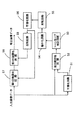
アプリケーション12dは画像処理した画像データをファイル形式で以降の処理プロセスに委ねるが、このように画像データをファイル形式で出力する過程が画像データ出力手段A4を構成する。なお、上述したようにディスプレイドライバ12bやプリンタドライバ12cが画像出力する際に鮮鋭化処理を実現する場合にはその出力段が画像データ出力手段A4を構成するといえる。 本実施形態においては、画像鮮鋭化装置をコンピュータシステム10として実現しているが、必ずしもかかるコンピュータシステムを必要とするわけではなく、同様の画像データに対して補間処理が必要なシステムであればよい。例えば、図3に示すようにデジタルスチルカメラ11b1内に強調処理する画像鮮鋭化装置を組み込み、強調処理した画像データを用いてディスプレイ17a1に表示させたりカラープリンタ17b1に印字させるようなシステムであっても良い。また、図4に示すように、コンピュータシステムを介することなく画像データを入力して印刷するカラープリンタ17b2においては、スキャナ11a2やデジタルスチルカメラ11b2あるいはモデム14a2等を介して入力される画像データについて自動的に強調処理するように構成することも可能である。このようなカラープリンタ17b2は、近年、ビデオプリンタとして家庭用テレビやビデオに接続して一場面をハードコピー化するのに使用されることも多く、着脱可能な記録メディアから画像データを取得しつつ解像度変換において最適な強調処理を実行すればよい。
【0037】
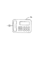
この他、図5に示すようなカラーファクシミリ装置18aや図6に示すようなカラーコピー装置18bといった画像データを扱う各種の装置においても当然に適用可能である。
上述した強調処理は、具体的には上記コンピュータ本体12内にて図7〜図9に示すフローチャートに対応した画像処理プログラムで行っている。また、図10は画像処理プログラム中での処理対象の変化を概略的に示している。なお、図10は画像処理プログラムの中でのワークエリアを示しており、RGBの3要素色のデータからなる各画像データはレイヤと呼ぶ個別のプレーンを想定したワークエリアを使用して処理対象となり、さらに各画像処理を制御するために演算結果などを格納するためにチャンネルというワークエリアを使用している。
【0038】
図7〜図9に示すフローチャートにおいて、ステップ100では画像データを入力する。この画像データはオペレーティングシステム12aを介してスキャナ11a2やデジタルスチルカメラ11b2あるいはモデム14a2等から取り込まれ、取り込んだ画像データは上述したレイヤにおけるオリジナル画像レイヤに格納される。
次に、オリジナル画像を残して処理を進めるためにオリジナル画像レイヤの画像データを背景レイヤと複製レイヤにコピーする(ステップ102、ステップ104)。本実施形態においては、この背景レイヤの画像データに対して最終的な強調処理を加えることとし、複製レイヤについてマスクを生成していくための画像処理を実施する。
【0039】
画像処理の最初に行なうのはトーンカーブ補正であり(ステップ106)、図12に示すトーンカーブを利用して複製レイヤに格納されている画像データのコントラストを上げている。ここでコントラストを上げる処理を行う意義については、後述することにする。
コントラストを上げた画像データについて、ステップ108では硬調複製レイヤにコピーしてオリジナルを残しておき、ステップ110では硬調複製レイヤの画像データに平滑化処理を実施する。平滑化処理は注目画素を中心とする所定領域について画像データの平均化を行なうものであり、図13に示すフィルタマスクを利用してフィルタ処理する。このフィルタ処理では、注目画素に隣接する8画素と注目画素の画像データを全て加え、画素数で除算するため、平均値を求めることに他ならない。図示するフィルタマスクは3×3画素の9画素であるが5×5画素というようなサイズの異なるフィルタマスクを使用しても良いし、周辺画素の重み付けを減らすような平滑化を行っても良い。
【0040】
平滑化した画像データは硬調複製レイヤに格納され、ステップ112では、硬調複製レイヤの画像データと複製レイヤの画像データとの差の絶対値を演算し、演算結果をアルファチャンネル1に格納する。
図14は、この一連の処理の意味するところを説明するための参考図であり、本来、二次元的な画像データを分かりやすく一次元的に並べ直したものである。複製レイヤの画像データが同図(a)に示すとおりであるとすると、平滑化することによって同図(b)に示すように段差部分が滑らかになる。次いで、両者の差分を演算すると同図(c)に示すように平滑化して変化した画素において差分値が生じ、かつ、その絶対値(図中一点鎖線で表れたもの)が大きくなるのは複製レイヤの画像データが大きく変化しているところである。この絶対値が大きい部分こそ画像が大きく変化しているところであり、この一連の処理は画像の鮮鋭領域を検出することに他ならない。また、ステップ106で複製レイヤの画像データのコントラストを上げたのは、上述した差分値を大きくすることに貢献し、鮮鋭領域の検出を行いやすくしている。この点、最初に鮮鋭領域を検出できれば以降においてその調整は任意に行えるが、鮮鋭領域を検出する段階で対象外となってしまうと調整の余地が小さくなる。従って、このように広めに鮮鋭領域を検出するようにしている。
【0041】
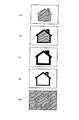
また、図15は具体的な画像イメージで上述した処理の意味するところをを説明している。同図(a)がオリジナルの画像であるとすると、平滑化処理することによって同図(b)に示すように輪郭部分の画像データに変化が表れ、それ以外の部分は元の色のままとなる。従って、オリジナルの画像との差分値を求めると、同図(c)に示すように元の画像の輪郭を中心とする領域だけが残るのである。
【0042】
アルファチャンネル1は汎用的なチャンネルであるので、差分値の絶対値を保存するためにアンシャープマスクオリジナルチャンネルとアンシャープマスク硬調化チャンネルとに格納しておき(ステップ114とステップ116)、以下に、具体的な演算結果を良好とするためのアンシャープマスク硬調化チャンネルに調整を行っていく。
まず、ステップ118では図16に示すトーンカーブを利用してトーンカーブ補正を行う。図14(c)に示すようにして画像の鮮鋭化に対応する差分値を得られても、このデータそのものが演算に利用しやすいとは限らない。特に、かかる差分値の絶対値自身は小さな値にしかならないので、より大きな値にする必要もある。図15に示すものでは、小さな絶対値を比例的に大きくさせることを目的としているが、あるしきい値を設定してそれ以下のものは余り変化させないような急峻なS字カーブを採用することも可能である。
【0043】
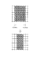
次に、ステップ120ではアンシャープマスク硬調化チャンネルの縮小化処理を実施する。縮小化処理は実際のイメージとして線の幅を狭めるような処理であり、図17に示すように1画素(1ピクセル)分だけ領域を狭める。上述したように、ステップ118ではしきい値の設定次第で脱落してしまいかねない画素を拾い上げている関係上、ステップ120では適度な範囲とするためにこのような縮小化を行っている。具体的な画像のイメージは図15(c)から同図(d)へと変化する。むろん、これはチューニングの範囲であり、適宜変更可能である。
【0044】
以上によって、鮮鋭な領域についての調整を行ったが、本発明で主に求めようとしているのは非鮮鋭領域であるから、ステップ122ではアンシャープマスク硬調化チャンネルを反転処理する。反転処理は単純に画像データの値を255から引いたものとする。従って、「255」は「0」に、「200」は「55」に「1」は「254」にというように変化する。反転した状態は図15(e)に示すようになり、当初の同図(a)において輪郭だった部分以外の領域に何らかの値を持つマスクが形成されたことになる。そして、マスクとしての処理の最後のものとして、ステップ124ではこのアンシャープマスク硬調化チャンネルに平滑化処理を施す。これにより、図15(e)に示すマスク画像での境界部分が滑らかになり、次に実施する強調処理で画像にジャンプが生じないようにすることを期待できる。
【0045】
そして、この完成したマスクを完成アンシャープマスク1チャンネルと完成アンシャープマスク2チャンネルにコピーし(ステップ126、ステップ128)、さらに完成アンシャープマスク2チャンネルについては反転処理を実施する(ステップ130)。このように反転処理を実施することにより、鮮鋭な領域を再度検出することになる。本実施形態においては、非鮮鋭領域について強い強調処理を行う一方、非鮮鋭領域についても弱い強調処理を行うため、敢えて完成アンシャープマスク2チャンネルとして鮮鋭領域を再度検出するようにしている。
【0046】
強調処理では図18〜図19に示すアンシャープマスクを使用する。ここで、ステップ132とステップ134で実施する強調処理について輝度を例として説明する。
強調前の各画素の輝度Yに対して強調後の輝度Y’は、
Y’=Y+Eenhance ・(Y−Yunsharp )
として演算される。このYunsharp は各画素の画像データに対してアンシャープマスク処理を施したものであり、強調係数Eenhance は上記完成アンシャープマスク1チャンネルと完成アンシャープマスク2チャンネルを「255」で除算して正規化した値である。
【0047】
ここでアンシャープマスク処理について説明する。図18〜図20は三つの大きさの異なるアンシャープマスク41〜43を示している。このアンシャープマスク41〜43は、中央の「100」の値をマトリクス状の画像データにおける処理対象画素Y(x,y)の重み付けとし、その周縁画素に対して同マスクの升目における数値に対応した重み付けをして積算するのに利用される。今、図19に示すアンシャープマスク42を利用するのであれば、
【0048】
【数1】

【0049】
このような演算の意味するところは次のようになる。Yunsharp (x,y)は注目画素に対して周縁画素の重み付けを低くして加算したものであるから、いわゆる「なまった(アンシャープ)」画像データとしていることになる。このようにしてなまらせたものはいわゆるローパスフィルタをかけたものと同様の意味あいを持つ。従って、「Y(x,y)−Yunsharp (x,y)」とは本来の全成分から低周波成分を引いたことになってハイパスフィルタをかけたものと同様の意味あいを持つ。そして、ハイパスフィルタを通過したこの高周波成分に対して強調係数Eenhance を乗算して「Y(x,y)」に加えれば同強調係数Eenhance に比例して高周波成分を増したことになり、エッジが強調される結果となる。
【0050】
また、エッジの強調度合いは、アンシャープマスクの大きさによっても変化する。縦横の升目数の異なる三つのアンシャープマスク41〜43であれば、大きなマスクほど注目画素の近隣の画素に対する重み付けが大きく、遠くの画素にいたるまでの距離の中で徐々に重み付けが減っていっている。これは言い換えればよりローパスフィルタとしての性格が強くなり、高周波成分を生成しやすくなるからである。
【0051】
従って、強調係数Eenhance による強調度合いの調整に加えて、大きなサイズのアンシャープマスク43を利用すれば強い強調処理を行うことになり、小さなサイズのアンシャープマスク41を利用すれば弱い強調処理を行うことになる。むろん、中間的な強さの強調処理を行うのであれば中間サイズのアンシャープマスク42を利用すればよくなる。
図9のフローチャートによれば、ステップ132にて非鮮鋭領域に強い強調処理を行うにはアンシャープマスク43を使用しつつ完成アンシャープマスク1チャンネルを強調係数として使用して演算を行うし、ステップ134にて鮮鋭領域に弱い強調処理を行うにはアンシャープマスク41を使用しつつ完成アンシャープマスク2チャンネルを強調係数として使用して演算を行うことになる。なお、アンシャープマスク41〜43のフィルタマスクは一例に過ぎず、適宜変更することも可能である。また、図19を参照すると分かるように、最外周のパラメータは「0」または「1」であり、画素の画像データに乗算しても「632」で除算した場合の影響度を考えると殆ど無意味である。このため、最外周のパラメータを無視して5×5画素としたアンシャープマスク44のフィルタマスクを使用すれば、除算の演算回数「49(=7×7)」回から「25(=5×5)」回へと半減し、演算処理時間を短縮化させることもできる。
【0052】
以上のような処理を経ることにより、デジタルスチルカメラ11b2あるいはモデム14a2等を介して取り込んだディジタルの画像データであっても、もともと鮮鋭なエッジ部分が過度にシャープになりすぎたり、妙に作り物の感じが強く表れてしまうということがなくなる。
このようにして得られた画像データ自体は背景レイヤに格納されており、この画像データをディスプレイドライバ12bやプリンタドライバ12cを介してディスプレイ17aやカラープリンタ17bに出力すると、綺麗な画像となっている。
【0053】
一般的にはこの強調処理で概ね自然な感じで画像の鮮鋭度が上がるが、人の肌が鮮鋭化してざらついた感じに見えることもあり得る。人自体が写真のオブジェクトであるため、特にその部分を注目してしまうためである。同様なことは、写真の中で広い面積を占める空の部分についても生じる。このような場合は、各画素が肌色や空色であるか否かを判断し、肌色や空色であったら強調処理を弱めるようにすればよい。ここで、各画素が肌色や空色であるか否かを判断する手法について説明する。
【0054】
各画素の画像データが(R,G,B)で表されるとすると、色度は、
r=R/(R+G+B)
b=B/(R+G+B)
として表される。
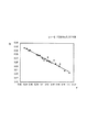
図21は人間の肌を表す画像データのサンプリング結果を示している。すなわち、左側の三つのデータは肌を構成する画素の(R,G,B)の値であり、その右方に(R+G+B)の合計(sum_rgb)を示し、その右方に上記計算に基づく色度r,bと輝度Yとを示している。また、図22は各画素についてrb空間にプロットした場合のグラフを示している。同図に示すように、RGBデータとしては統一性を見出しにくいようでも、色度としてグラフにプロットしてみると規則性があることが見出される。すなわち、人の肌であれば暗く写っているときも明るく写っているときもあり得るが、それにもかかわらず、図11に示すように直線状に分布しているのである。同図に示す直線状の分布は、
0.33<r<0.51
|0.74r+b−0.57|<0.1
なる関係式が成立しているといえるから、各画素についてこの条件があてはめられれば肌色領域に属するものといえる。
【0055】
また、図23は同様にして青空を表す画像データのサンプリング結果を示しているとともに図24は各画素についてrb空間にプロットした場合のグラフを示しており、この場合は肌色の場合よりも変動幅が大きいことを考慮すると、
0.17<r<0.30
|1.11r+b−0.70|<0.2
なる関係式が成立しているといえる。
図25は、ステップ132の内部でこのような処理を実行するフローチャートを示しており、ステップ132aにて色度を計算し、ステップ132bとステップ132cとで肌色や空色であるかを判断し、いずれにも引っかからなければステップ132dで強い強調処理を実行する。しかし、ステップ132bとステップ132cのいずれかで肌色や空色であると判断されると、ステップ132eで弱い強調処理を実行する。例えば、強調係数Eenhance として完成アンシャープマスク2チャンネルのものを利用しても良いし、小さいサイズのアンシャープマスク41を使用しても良い。
【0056】
ところで、以上の処理はコンピュータシステム10を使用しつつ主にソフトウェア的な処理で実現している。しかしながら、本発明は必ずしもソフトウェア的な構成に限るものではなく、ハードウェアによるワイヤロジックで実現することもできる。
図26は具体的なブロック回路を示しており、入力画像データは平滑化回路51に入力されてぼかしの処理を経たものと経ていないものとを差分絶対値回路52に入力し、両者の差分値の絶対値を演算し、トーンカーブ補正回路53で図16に示すようなトーンカーブ補正を実施する。次いで、縮小化回路54では外縁部を狭める処理を実行し、反転回路55で反転させた後、平滑化回路56で最後の平滑化処理を実施する。この後、生成されたマスクデータを使用して第一の強調化回路57で強い強調化を施し、反転回路58を経たマスクデータを使用して第二の強調化回路59で弱い強調化を施す。
【0057】
各回路ではロジック回路でディジタル的に処理すればよいが、一部ではアナログ化して処理しても良い。
このように、デジタルスチルカメラ11b2等を介して取り込んだディジタルの画像データは、平滑化してぼかしたものと元のものとの差を演算し(ステップ112)て鮮鋭化領域を検出した後、トーンカーブ補正や縮小や反転や平滑化処理の各処理(ステップ118〜122)を経て非鮮鋭領域のマスクデータを完成アンシャープマスク1チャンネルに形成し、同マスクデータを使用して元の画像データに強い強調処理を施すようにした(ステップ132)ため、もともと鮮鋭なエッジ部分が過度にシャープになりすぎたり、妙に作り物の感じが強く表れてしまうということがなくなる。この場合、画像調整のための処理も含まれるし、鮮鋭な領域に対して弱い強調処理(ステップ134)を実施したりしている。
【図面の簡単な説明】
【図1】 本発明の一実施形態にかかる画像鮮鋭化装置のクレーム対応図である。
【図2】 本発明の一実施形態にかかる画像鮮鋭化装置が適用されるコンピュータシステ
ムのブロック図である。
【図3】 本発明の画像鮮鋭化装置の他の適用例を示す概略ブロック図である。
【図4】 本発明の画像鮮鋭化装置の他の適用例を示す概略ブロック図である。
【図5】 本発明の画像鮮鋭化装置の他の適用例を示す概略ブロック図である。
【図6】 本発明の画像鮮鋭化装置の他の適用例を示す概略ブロック図である。
【図7】 本発明の一実施形態にかかる画像鮮鋭化装置のフローチャートの一部である。
【図8】 同フローチャートの一部である。
【図9】 同フローチャートの一部である。
【図10】 処理の全体を示す概略ブロック図である。
【図11】 データの格納状態を示す概念図である。
【図12】 トーンカーブの一例を示す図である。
【図13】 平滑化処理に使用するフィルタマスクを示す図である。
【図14】 画像データの変化過程を示す概念図である。
【図15】 画像の変化過程を示す概念図である。
【図16】 トーンカーブの一例を示す図である。
【図17】 縮小化処理の過程を示す図である。
【図18】 小サイズのアンシャープマスクを示す図である。
【図19】 中サイズのアンシャープマスクを示す図である。
【図20】 大サイズのアンシャープマスクを示す図である。
【図21】 肌色の画素の画像データと色度と輝度を示す図である。
【図22】 肌色の画素を色度のグラフで示す図である。
【図23】 空色の画素の画像データと色度と輝度を示す図である。
【図24】 空色の画素を色度のグラフで示す図である。
【図25】 強調処理の変形例を示すフローチャートの一部である。
【図26】 ハードウェアロジックで実現した画像鮮鋭化装置のブロック図である。
【符号の説明】
10…コンピュータシステム
11a…スキャナ
11a2…スキャナ
11b…デジタルスチルカメラ
11b1…デジタルスチルカメラ
11b2…デジタルスチルカメラ
11c…ビデオカメラ
12…コンピュータ本体
12a…オペレーティングシステム
12b…ディスプレイドライバ
12b…ドライバ
12c…プリンタドライバ
12d…アプリケーション
13a…フロッピーディスクドライブ
13b…ハードディスク
13c…CD−ROMドライブ
14a…モデム
14a2…モデム
15a…キーボード
15b…マウス
17a…ディスプレイ
17a1…ディスプレイ
17b…カラープリンタ
17b1…カラープリンタ
17b2…カラープリンタ
18a…カラーファクシミリ装置
18b…カラーコピー装置
41〜43…アンシャープマスク
51…平滑化回路
52…差分絶対値回路
53…トーンカーブ補正回路
54…縮小化回路
55…反転回路
56…平滑化回路
57…第一の強調化回路
58…反転回路
59…第二の強調化回路[0001]
BACKGROUND OF THE INVENTION
The present invention relates to an image sharpening method and an image sharpening apparatus .
[0002]
[Prior art]
When an image is handled by a computer or the like, the image is expressed by a dot matrix pixel, and each pixel is expressed by a gradation value. For example, a photograph is often displayed on a computer screen with pixels of 640 dots in the horizontal direction and 480 dots in the vertical direction.
[0003]
Since each pixel has data representing color and brightness, image processing is performed by changing this data. At this time, a sharpening process for sharply displaying a blurred image is widely performed, and the entire image is uniformly sharpened.
[0004]
[Problems to be solved by the invention]
In the conventional image sharpening device described above, sharpening processing is uniformly applied to the entire image, but originally sharp edges and the like are excessively sharp, and the generated image is strangely shaped. There was a problem that the feeling of was strongly expressed.
[0005]
The present invention has been made in view of the above problems, and an object of the present invention is to provide an image sharpening method and an image sharpening apparatus capable of sharpening with a more natural feeling.
[0006]
[Means for Solving the Problems]
In order to achieve the above object, the invention according to
[0007]
In the invention according to
[0008]
That is, an unsharp area is detected and the area is sharpened.
The image data may be obtained by acquiring image data already stored in a storage area, or obtained by sequentially inputting image data that is input like a camera. It can be modified as appropriate.
The same applies to the image data output process, where the output destination is a specific recording medium, a temporary storage area such as a memory, or an output destination via a communication line such as a network. good.
[0009]
Further, the image sharpening process itself may be one of a plurality of processes in the image process. In this case, the image data is substantially read / written from / to the image data acquired by the other process. Become.
That is, the input / output of the image data may be in any form as long as it can be processed in the following unsharpened area detecting step and image sharpening step. In addition, the image data may be any image in which the image is expressed in multi-tone with dot matrix pixels, and may be a monochrome image or a color image. In the case of a color image, the coordinate system in the color space is used. There is no particular limitation on the method of taking, the gradation range, and the like.
[0010]
The unsharp region detection step, detecting the unsharp regions of the original image, the specific method is varied, as an example, in the above SL unsharp region detection step, and manpower original image data, the image It is good also as a structure which detects an area | region with a small difference with the smoothed image data which applied the smoothing process with respect to data as an unsharp area | region.
[0011]
Oite on Symbol configuration, while leaving the input image data as original image data, to generate a smoothed image data by applying a smoothing processing on the image data, on the said unsharp regions In the detection step, an area where the difference between the original image data and the smoothed image data is small is detected as an unsharp area.
The smoothing process generates a pixel averaged with pixels around the target central pixel, which can be said to be an expected value of the central pixel when viewed from the peripheral pixels. If the difference from the specific value at the central pixel is to be obtained, the smaller the difference from the expected value, the smaller the change in the pixel, excluding so-called edge or high frequency pixels. Represents an unsharp area.
[0012]
However, even if an unsharp area is known as described above, the difference value itself is not always easy to use in subsequent processing. Therefore, the unsharp area detection step may be configured to adjust the detection range of the unsharp area by correcting the tone curve for the difference value between the original image data and the smoothed image data.
[0013]
With this configuration, tone curve correction is performed for the difference value between the original image data and the smoothed image data. When the difference value is used as it is, there may be a case where the semantic content is greatly different at a certain threshold. Even in such a case, the detection range of the non-sharp area can be adjusted by adding weight to the meaning of the difference value using the tone curve.
Since detection of a non-sharp area and detection of a sharp area are in a relation of front and back, it should be considered that the area to be detected is not necessarily limited to the non-sharp area itself. As an example, in the above SL unsharp region detection step detects a region having a large difference from the above original image data and the smoothed image data as sharpness area, in the image sharpening process, by reversing the same sharpness area Te while the non鮮銃area on the original image data of the unsharp regions as a mask and smoothed, the image may be configured to be sharpened on the basis of the difference between the original raw image data.
[0014]
Oite above Symbol arrangement detects a region having a large difference from the above original image data and the smoothed image data as sharpness area. Therefore, although it appears that the unsharp area is not detected on the surface, since the remaining area is actually the unsharp area, the non-sharp area detecting step detects the unsharp area. become. This inversion state is eliminated by the image sharpening process.
That is, in the image sharpening process, the original image data is smoothed using the non-sharp area as a mask while inverting the sharp area, thereby making the non-sharp area. Further, if the smoothed image is subtracted from the original image, the high-frequency component remains and is sharpened.
[0015]
Adjustment of the boundary between sharpening area and unsharp regions is not limited to the tone curve correction described above, as an example, may be configured to invert from shrinking the upper Symbol detected sharpness regions.
Oite on Symbol configuration, since the first reduction of the detected sharpness regions, it will detect a sharp areas sharp. After this, it reverses, but the sharpness acts to widen the outer edge of the unsharp area.
[0016]
Similarly, as another example for adjusting the boundary between the sharpening area and unsharp regions, above Symbol unsharp region detection process may be configured to apply a smoothing process to the edge of the unsharp regions.
Oite on Symbol configuration, for applying smoothing processing to the edge of the unsharp regions, edge by the exertion is more or less moved in and out, will be adjusted. In this case, it is not always necessary to apply the smoothing process only to the edge portion, and the same can be said to apply the smoothing process to the entire image.
[0017]
Depending on the value of the original image data, the judgment may change even with the same sharpness. For example, when the overall darkness and the overall brightness are considered to be proportional to the degree of change in brightness, it should be determined that the unsharp area is large in the darker side. However, such results are not reasonable made, as suitable examples of the measures, in the above SL unsharp region detection step, pre tone curve correction to the keep in unsharp regions with respect to the original image data It is good also as a structure utilized for the detection of this.
[0018]
Oite on Symbol configuration, since previously the tone curve correction to the original image data, so obtained a reasonable area when detecting said unsharp regions. Moreover, it is naturally possible to make an adjustment consciously without being limited to the purpose of adjusting the brightness.
Although failure of the prior art are overcome by sharpening unsharp regions, this does not necessarily exclude the sharpening sharpening area, as an example, in the above Symbol image sharpening process, also sharp region It is good also as a structure sharpened weakly rather than the said non-sharp area | region.
[0019]
Oite on Symbol configuration, the unsharp regions in the image sharpening process for sharpening, sharpening also sharp region. If the sharpening of the sharp area seems to be stronger than the sharpening of the non-sharp area, there is no difference from the prior art, so it is made weaker than the non-sharp area.
This is effective when the balance with the original sharp region is lost due to the sharpening of the non-sharp region. The degree of sharpening may be determined in advance at a fixed ratio between the non-sharp area and the sharp area, or the sharpness of the sharp area may be adjusted as appropriate according to the specific situation.
[0020]
On the other hand, depending on a specific subject, the observer's line of sight may concentrate and appear rough. In particular, the skin-colored region can be uncomfortable even though it is a good feeling as image data because it is sensitive to helping to be an original subject. Preferable examples in such a case, the upper Symbol image sharpening process may be configured to reduce the sharpening degree for the color region grainy in sharpening.
[0021]
Oite above Symbol arrangement, for reducing the sharpening degree for skin color and sky is the color area grainy in sharpening, it will reduce the inter-roughness. The color region may be determined by chromaticity, and if it is chromaticity, it is not affected by luminance, so that human skin can be detected regardless of whether it is bright or dark. The color region may be other than the skin color or sky blue, and can be adjusted as appropriate.
[0022]
As described above, it is easy to understand that the method for sharpening the non-sharp area is realized in a substantial apparatus, and in that sense, the present invention can also be applied as a substantial apparatus. For this reason, the invention according to
That is, there is no difference in that it is effective as a substantial device. Such an image sharpening device may be implemented alone, or may be implemented together with other methods in a state of being incorporated in a certain device. Including embodiments. Therefore, it can be changed as appropriate, such as software or hardware.
[0023]
In the case of software that implements an image sharpening method as an embodiment of the idea of the invention, it naturally exists on a recording medium that records such software, and it must be used.
As an example, a medium recording an image sharpening processing program for sharpening an image by a computer based on the images in the image data multi-gradation pixels in dot matrix, input original image data And a non-sharp region detection step for detecting the non-sharp region while adjusting the detection range of the non-sharp region by correcting the tone curve for the difference value between the smoothed image data obtained by performing the smoothing process on the image data, A configuration is also possible in which the computer executes an image sharpening step for sharpening relatively strongly the detected portion and the non-sharp region in the image data, and an image data output step for outputting the sharpened image data. There is .
Of course, the recording medium may be a magnetic recording medium, a magneto-optical recording medium, or any recording medium that will be developed in the future. In addition, the duplication stages such as the primary duplication product and the secondary duplication product are equivalent without any question.
Further, even when a part is software and a part is realized by hardware, the idea of the invention is not completely different, and a part is stored on a recording medium and is appropriately changed as necessary. It may be in the form of being read. Of course, it goes without saying that the idea of the invention is reflected in the program itself.
[0024]
Of course, such an image sharpening method may be carried out independently or may be carried out together with other methods in a state of being incorporated in a certain device. Various embodiments are included and can be changed as appropriate.
[0025]
【The invention's effect】
As described above, the present invention can provide an image sharpening method capable of sharpening an image with a natural feeling and easily adjusting the detection range of an unsharp area .
[0026]
Furthermore , since the non- sharp area can be detected as a reflective effect for detecting the sharp area instead of directly detecting the non-sharp area, more flexible processing is possible.
Furthermore , the adjustment of the boundary between the non- sharp area and the sharp area can be flexibly performed.
[0027]
The present invention according to
[0028]
DETAILED DESCRIPTION OF THE INVENTION
FIG. 1 shows an image sharpening apparatus according to an embodiment of the present invention by a claim correspondence diagram, and FIG. 2 shows a
The
[0029]
A
In addition, a
[0030]
Furthermore, a
[0031]
The
On the other hand, in order to display or output to the image output device while inputting an image using such an image input device, a predetermined program is executed in the computer
[0032]
The
[0033]
By the way, an image photographed by the digital
[0034]
In the above, the process of acquiring the image data from the image input device or the like constitutes the image data acquisition means A1 shown in FIG. 1, and the hardware and software related thereto are actually applicable. Further, the non-sharp area detection means A2 corresponds to a process of detecting an area with relatively low sharpness in the image data acquired in this way, and is specifically implemented by the
[0035]
In the present embodiment, the
Of course, the
[0036]
The
[0037]
In addition, the present invention can naturally be applied to various apparatuses that handle image data such as a
Specifically, the above-described enhancement processing is performed in the computer
[0038]
In the flowcharts shown in FIGS. 7 to 9, in
Next, the image data of the original image layer is copied to the background layer and the duplicate layer in order to leave the original image and proceed with processing (
[0039]
Tone curve correction is performed at the beginning of image processing (step 106), and the contrast of the image data stored in the duplicate layer is increased using the tone curve shown in FIG. Here, the significance of performing the process of increasing the contrast will be described later.
In
[0040]
The smoothed image data is stored in the hard copy layer, and in
FIG. 14 is a reference diagram for explaining the meaning of this series of processing. Originally, two-dimensional image data is rearranged in an easy-to-understand one-dimensional manner. If the image data of the duplicate layer is as shown in FIG. 5A, the stepped portion becomes smooth as shown in FIG. Next, when the difference between the two is calculated, a difference value is generated in the pixel which has been smoothed and changed as shown in FIG. 6C, and the absolute value (shown by a one-dot chain line in the figure) becomes large. The image data of the layer is changing greatly. The portion where the absolute value is large is where the image is greatly changed, and this series of processing is nothing but detecting a sharp region of the image. Further, increasing the contrast of the image data of the duplicate layer in
[0041]
FIG. 15 illustrates the meaning of the above-described processing with a specific image. Assuming that FIG. 5A is the original image, the smoothing process causes a change in the image data of the contour portion as shown in FIG. 5B, and the other portions remain in the original color. Become. Therefore, when the difference value from the original image is obtained, only the region centered on the contour of the original image remains as shown in FIG.
[0042]
Since
First, in
[0043]
Next, in
[0044]
Although the sharp region has been adjusted as described above, since it is the non-sharp region that is mainly sought in the present invention, in
[0045]
Then, the completed mask is copied to the completed
[0046]
In the enhancement process, an unsharp mask shown in FIGS. 18 to 19 is used. Here, the enhancement processing performed in
The luminance Y ′ after enhancement with respect to the luminance Y of each pixel before enhancement is
Y '= Y + Eenhance (Y-Yunsharp)
Is calculated as This Yunsharp is obtained by applying unsharp mask processing to the image data of each pixel, and the enhancement coefficient Eenhance is normalized by dividing the completed
[0047]
Here, the unsharp mask process will be described. 18 to 20 show three
[0048]
[Expression 1]
[0049]
The meaning of such an operation is as follows. Yunsharp (x, y) is obtained by lowering the weight of the peripheral pixel with respect to the target pixel and adding it, so that it is so-called “unsharp” image data. What is smoothed in this way has the same meaning as that obtained by applying a so-called low-pass filter. Therefore, “Y (x, y) −Yunsharp (x, y)” has the same meaning as that obtained by applying the high-pass filter by subtracting the low frequency component from the original all components. If the high frequency component that has passed through the high-pass filter is multiplied by the enhancement coefficient Eenhance and added to “Y (x, y)”, the high frequency component is increased in proportion to the enhancement coefficient Eenhance, and the edge is increased. The result is emphasized.
[0050]
Also, the degree of edge enhancement varies depending on the size of the unsharp mask. In the case of three
[0051]
Therefore, in addition to the adjustment of the degree of enhancement by the enhancement coefficient Eenhance, strong enhancement processing is performed if the large-size
According to the flowchart of FIG. 9, in order to perform strong enhancement processing in the unsharp area in
[0052]
Through the above processing, even digital image data captured via the digital still camera 11b2 or the modem 14a2 or the like, the sharp edge portion is originally too sharp, There is no longer a strong feeling.
The image data itself obtained in this way is stored in the background layer, and when this image data is output to the
[0053]
In general, this enhancement process increases the sharpness of the image with a generally natural feeling, but the human skin may be sharpened and look rough. This is because the person himself / herself is a photographic object, and particularly pays attention to that portion. The same thing happens for empty areas that occupy a large area in a photograph. In such a case, it may be determined whether each pixel is a skin color or sky blue, and if it is a skin color or sky blue, the enhancement process may be weakened. Here, a method for determining whether or not each pixel is a skin color or sky blue will be described.
[0054]
If the image data of each pixel is represented by (R, G, B), the chromaticity is
r = R / (R + G + B)
b = B / (R + G + B)
Represented as:
FIG. 21 shows a sampling result of image data representing human skin. That is, the three data on the left are the values of (R, G, B) of the pixels constituting the skin, and the sum (sum_rgb) of (R + G + B) is shown on the right, and the color based on the above calculation is shown on the right. Degrees r, b and luminance Y are shown. FIG. 22 shows a graph when each pixel is plotted in the rb space. As shown in the figure, even if it is difficult to find unity as RGB data, it is found that there is regularity when plotted on a graph as chromaticity. In other words, human skin may appear dark or bright, but nevertheless, it is distributed linearly as shown in FIG. The linear distribution shown in the figure is
0.33 <r <0.51
| 0.74r + b−0.57 | <0.1
Therefore, if this condition is applied to each pixel, it can be said that it belongs to the skin color region.
[0055]
Similarly, FIG. 23 shows the sampling result of the image data representing the blue sky, and FIG. 24 shows a graph when each pixel is plotted in the rb space. In this case, the fluctuation range is larger than that in the case of skin color. Considering that is large,
0.17 <r <0.30
| 1.11r + b−0.70 | <0.2
It can be said that the following relational expression holds.
FIG. 25 shows a flowchart for executing such processing in
[0056]
By the way, the above processing is realized mainly by software processing while using the
FIG. 26 shows a specific block circuit. The input image data is input to the smoothing
[0057]
Each circuit may be digitally processed by a logic circuit, but some may be processed in an analog manner.
In this way, the digital image data captured via the digital still camera 11b2 or the like calculates the difference between the smoothed and blurred image and the original image (step 112), detects the sharpened area, After the curve correction, reduction, inversion, and smoothing processes (
[Brief description of the drawings]
FIG. 1 is a view corresponding to claims of an image sharpening device according to an embodiment of the present invention.
FIG. 2 is a block diagram of a computer system to which an image sharpening apparatus according to an embodiment of the present invention is applied.
FIG. 3 is a schematic block diagram illustrating another application example of the image sharpening device of the present invention.
FIG. 4 is a schematic block diagram showing another application example of the image sharpening device of the present invention.
FIG. 5 is a schematic block diagram illustrating another application example of the image sharpening device of the present invention.
FIG. 6 is a schematic block diagram illustrating another application example of the image sharpening device of the present invention.
FIG. 7 is a part of a flowchart of an image sharpening apparatus according to an embodiment of the present invention.
FIG. 8 is a part of the flowchart.
FIG. 9 is a part of the flowchart.
FIG. 10 is a schematic block diagram showing the entire processing.
FIG. 11 is a conceptual diagram showing a data storage state.
FIG. 12 is a diagram illustrating an example of a tone curve.
FIG. 13 is a diagram showing a filter mask used for smoothing processing.
FIG. 14 is a conceptual diagram showing a change process of image data.
FIG. 15 is a conceptual diagram illustrating a process of changing an image.
FIG. 16 is a diagram illustrating an example of a tone curve.
FIG. 17 is a diagram illustrating a process of a reduction process.
FIG. 18 is a diagram showing a small-sized unsharp mask.
FIG. 19 is a diagram showing a medium-sized unsharp mask.
FIG. 20 is a view showing a large-sized unsharp mask.
FIG. 21 is a diagram illustrating image data, chromaticity, and luminance of a flesh color pixel.
FIG. 22 is a diagram illustrating skin-colored pixels in a chromaticity graph.
FIG. 23 is a diagram illustrating image data, chromaticity, and luminance of sky blue pixels.
FIG. 24 is a diagram illustrating a sky blue pixel by a graph of chromaticity.
FIG. 25 is a part of a flowchart showing a modification of the enhancement process.
FIG. 26 is a block diagram of an image sharpening device realized by hardware logic.
[Explanation of symbols]
DESCRIPTION OF
Claims (2)
上記画像データにおける上記非鮮鋭領域と検出された部位について相対的に強く鮮鋭化する画像鮮鋭化工程と、
鮮鋭化された画像データを出力する画像データ出力工程とを具備し、
上記非鮮鋭領域検出工程では、入力された原画像データとこの画像データに対して平滑化処理をかけた平滑化画像データとの差分が大きい領域を鮮鋭領域として検出するとともに、
上記画像鮮鋭化工程では、上記検出された鮮鋭領域を縮小化してから反転させて非鮮銃領域としつつこの非鮮鋭領域をマスクとして上記原画像データを平滑化処理した上で、元の原画像データとの差に基づいて画像を鮮鋭化することを特徴とする画像鮮鋭化方法。A non-sharp area detection step for detecting a non-sharp area of the original image based on image data in which an image is expressed in multi-tone with a dot matrix pixel;
An image sharpening step for sharpening relatively strongly about the non-sharp area and the detected part in the image data;
An image data output step for outputting sharpened image data,
In the non-sharp area detection step, an area having a large difference between the input original image data and the smoothed image data obtained by smoothing the image data is detected as a sharp area,
In the image sharpening step, the detected sharp area is reduced and then inverted to form a non-sharp gun area, the original image data is smoothed using the non-sharp area as a mask, and then the original original image An image sharpening method comprising sharpening an image based on a difference from data .
上記画像データにおける上記非鮮鋭領域と検出された部位について相対的に強く鮮鋭化する画像鮮鋭化手段と、
鮮鋭化された画像データを出力する画像データ出力手段とを具備し、
上記非鮮鋭領域検出手段では、入力された原画像データとこの画像データに対して平滑化処理をかけた平滑化画像データとの差分が大きい領域を鮮鋭領域として検出するとともに、
上記画像鮮鋭化手段では、上記検出された鮮鋭領域を縮小化してから反転させて非鮮銃領域としつつこの非鮮鋭領域をマスクとして上記原画像データを平滑化処理した上で、元の原画像データとの差に基づいて画像を鮮鋭化することを特徴とする画像鮮鋭化装置。A non-sharp area detecting means for detecting a non-sharp area of the original image based on image data in which an image is expressed in multi-tone with a dot matrix pixel;
Image sharpening means for sharpening relatively strongly about the non-sharp region and the detected portion in the image data;
Image data output means for outputting sharpened image data,
The non-sharp area detection means detects an area having a large difference between the input original image data and the smoothed image data obtained by smoothing the image data as a sharp area,
The image sharpening means reduces the detected sharp area and then inverts it to make a non-sharp gun area, smooths the original image data using the non-sharp area as a mask, and then the original original image. An image sharpening apparatus characterized by sharpening an image based on a difference from data .
Priority Applications (1)
| Application Number | Priority Date | Filing Date | Title |
|---|---|---|---|
| JP09377699A JP4019239B2 (en) | 1999-03-31 | 1999-03-31 | Image sharpening method and image sharpening device |
Applications Claiming Priority (1)
| Application Number | Priority Date | Filing Date | Title |
|---|---|---|---|
| JP09377699A JP4019239B2 (en) | 1999-03-31 | 1999-03-31 | Image sharpening method and image sharpening device |
Publications (3)
| Publication Number | Publication Date |
|---|---|
| JP2000285232A JP2000285232A (en) | 2000-10-13 |
| JP2000285232A5 JP2000285232A5 (en) | 2004-10-14 |
| JP4019239B2 true JP4019239B2 (en) | 2007-12-12 |
Family
ID=14091836
Family Applications (1)
| Application Number | Title | Priority Date | Filing Date |
|---|---|---|---|
| JP09377699A Expired - Fee Related JP4019239B2 (en) | 1999-03-31 | 1999-03-31 | Image sharpening method and image sharpening device |
Country Status (1)
| Country | Link |
|---|---|
| JP (1) | JP4019239B2 (en) |
Cited By (1)
| Publication number | Priority date | Publication date | Assignee | Title |
|---|---|---|---|---|
| CN104344863A (en) * | 2013-07-29 | 2015-02-11 | 株式会社堀场制作所 | Measuring apparatus of liquid and apparatus for analyzing water quality |
Families Citing this family (4)
| Publication number | Priority date | Publication date | Assignee | Title |
|---|---|---|---|---|
| JP6417851B2 (en) * | 2014-10-28 | 2018-11-07 | ブラザー工業株式会社 | Image processing apparatus and computer program |
| KR101617551B1 (en) * | 2014-12-18 | 2016-05-03 | 재단법인 다차원 스마트 아이티 융합시스템 연구단 | Image processing method and system for improving face detection |
| KR102087681B1 (en) | 2015-09-17 | 2020-03-11 | 삼성전자주식회사 | Image processing device, method for processing image and computer-readable recording medium |
| CN111080535A (en) * | 2019-11-05 | 2020-04-28 | 浙江大华技术股份有限公司 | Image enhancement method and computer storage medium |
-
1999
- 1999-03-31 JP JP09377699A patent/JP4019239B2/en not_active Expired - Fee Related
Cited By (1)
| Publication number | Priority date | Publication date | Assignee | Title |
|---|---|---|---|---|
| CN104344863A (en) * | 2013-07-29 | 2015-02-11 | 株式会社堀场制作所 | Measuring apparatus of liquid and apparatus for analyzing water quality |
Also Published As
| Publication number | Publication date |
|---|---|
| JP2000285232A (en) | 2000-10-13 |
Similar Documents
| Publication | Publication Date | Title |
|---|---|---|
| JP4492704B2 (en) | Edge enhancement processing device, output device, edge enhancement processing method, and computer-readable recording medium | |
| US6822762B2 (en) | Local color correction | |
| JP4707830B2 (en) | A method for improving digital images with noise-dependent control of textures | |
| JP4902837B2 (en) | How to convert to monochrome image | |
| US6813041B1 (en) | Method and apparatus for performing local color correction | |
| EP1408448B1 (en) | Image processing method, image processing apparatus, image processing program and image recording apparatus | |
| KR20040044556A (en) | Image processing method, apparatus, and program | |
| JP2001229377A (en) | Method for adjusting contrast of digital image by adaptive recursive filter | |
| JP6417851B2 (en) | Image processing apparatus and computer program | |
| JP2008511048A (en) | Image processing method and computer software for image processing | |
| JP4064023B2 (en) | Digital image halftone processing method and apparatus, and recording medium on which digital image halftone processing program is recorded | |
| US6115078A (en) | Image sharpness processing method and apparatus, and a storage medium storing a program | |
| JP2008011286A (en) | Image processing program and image processor | |
| JP4243362B2 (en) | Image processing apparatus, image processing method, and recording medium recording image processing program | |
| JP4019239B2 (en) | Image sharpening method and image sharpening device | |
| JP2000285232A5 (en) | ||
| JP4161141B2 (en) | Edge enhancement processing apparatus, edge enhancement processing method, and computer-readable recording medium recording an edge enhancement processing program | |
| JP3981785B2 (en) | Medium storing image sharpening program, image sharpening device, and image sharpening method | |
| JPH10340332A (en) | Image processor, image processing method and medium recording image processing control program | |
| JP4067538B2 (en) | Image processing method, image processing apparatus, image forming apparatus, computer program, and recording medium | |
| JP4081628B2 (en) | Image data interpolation method, image data interpolation device, and computer readable recording medium recording image data interpolation program | |
| JPH11284860A (en) | Image processing method, image processing unit and recording medium recording image processing program and read by computer | |
| JP2000285231A5 (en) | ||
| JP2000013607A (en) | Image processing utilizing gradation processing | |
| JPH10200756A (en) | Image processing unit, image processing method, and medium recording image processing program |
Legal Events
| Date | Code | Title | Description |
|---|---|---|---|
| A977 | Report on retrieval |
Free format text: JAPANESE INTERMEDIATE CODE: A971007 Effective date: 20060929 |
|
| A131 | Notification of reasons for refusal |
Free format text: JAPANESE INTERMEDIATE CODE: A131 Effective date: 20061004 |
|
| A521 | Request for written amendment filed |
Free format text: JAPANESE INTERMEDIATE CODE: A523 Effective date: 20061204 |
|
| A02 | Decision of refusal |
Free format text: JAPANESE INTERMEDIATE CODE: A02 Effective date: 20070606 |
|
| A521 | Request for written amendment filed |
Free format text: JAPANESE INTERMEDIATE CODE: A523 Effective date: 20070704 |
|
| A911 | Transfer to examiner for re-examination before appeal (zenchi) |
Free format text: JAPANESE INTERMEDIATE CODE: A911 Effective date: 20070813 |
|
| TRDD | Decision of grant or rejection written | ||
| A01 | Written decision to grant a patent or to grant a registration (utility model) |
Free format text: JAPANESE INTERMEDIATE CODE: A01 Effective date: 20070829 |
|
| A61 | First payment of annual fees (during grant procedure) |
Free format text: JAPANESE INTERMEDIATE CODE: A61 Effective date: 20070911 |
|
| FPAY | Renewal fee payment (event date is renewal date of database) |
Free format text: PAYMENT UNTIL: 20101005 Year of fee payment: 3 |
|
| R150 | Certificate of patent or registration of utility model |
Free format text: JAPANESE INTERMEDIATE CODE: R150 |
|
| FPAY | Renewal fee payment (event date is renewal date of database) |
Free format text: PAYMENT UNTIL: 20101005 Year of fee payment: 3 |
|
| FPAY | Renewal fee payment (event date is renewal date of database) |
Free format text: PAYMENT UNTIL: 20111005 Year of fee payment: 4 |
|
| FPAY | Renewal fee payment (event date is renewal date of database) |
Free format text: PAYMENT UNTIL: 20121005 Year of fee payment: 5 |
|
| FPAY | Renewal fee payment (event date is renewal date of database) |
Free format text: PAYMENT UNTIL: 20121005 Year of fee payment: 5 |
|
| FPAY | Renewal fee payment (event date is renewal date of database) |
Free format text: PAYMENT UNTIL: 20131005 Year of fee payment: 6 |
|
| S531 | Written request for registration of change of domicile |
Free format text: JAPANESE INTERMEDIATE CODE: R313531 |
|
| R350 | Written notification of registration of transfer |
Free format text: JAPANESE INTERMEDIATE CODE: R350 |
|
| LAPS | Cancellation because of no payment of annual fees |