JP4017917B2 - Signal reception method - Google Patents
Signal reception method Download PDFInfo
- Publication number
- JP4017917B2 JP4017917B2 JP2002147977A JP2002147977A JP4017917B2 JP 4017917 B2 JP4017917 B2 JP 4017917B2 JP 2002147977 A JP2002147977 A JP 2002147977A JP 2002147977 A JP2002147977 A JP 2002147977A JP 4017917 B2 JP4017917 B2 JP 4017917B2
- Authority
- JP
- Japan
- Prior art keywords
- tfci
- channel
- receiver
- symbols
- estimation
- Prior art date
- Legal status (The legal status is an assumption and is not a legal conclusion. Google has not performed a legal analysis and makes no representation as to the accuracy of the status listed.)
- Expired - Fee Related
Links
Images


Classifications
-
- H—ELECTRICITY
- H04—ELECTRIC COMMUNICATION TECHNIQUE
- H04L—TRANSMISSION OF DIGITAL INFORMATION, e.g. TELEGRAPHIC COMMUNICATION
- H04L25/00—Baseband systems
- H04L25/02—Details ; arrangements for supplying electrical power along data transmission lines
- H04L25/0202—Channel estimation
- H04L25/0224—Channel estimation using sounding signals
- H04L25/0226—Channel estimation using sounding signals sounding signals per se
-
- H—ELECTRICITY
- H04—ELECTRIC COMMUNICATION TECHNIQUE
- H04B—TRANSMISSION
- H04B1/00—Details of transmission systems, not covered by a single one of groups H04B3/00 - H04B13/00; Details of transmission systems not characterised by the medium used for transmission
- H04B1/69—Spread spectrum techniques
- H04B1/707—Spread spectrum techniques using direct sequence modulation
- H04B1/7097—Interference-related aspects
- H04B1/711—Interference-related aspects the interference being multi-path interference
- H04B1/7115—Constructive combining of multi-path signals, i.e. RAKE receivers
-
- H—ELECTRICITY
- H04—ELECTRIC COMMUNICATION TECHNIQUE
- H04B—TRANSMISSION
- H04B7/00—Radio transmission systems, i.e. using radiation field
- H04B7/24—Radio transmission systems, i.e. using radiation field for communication between two or more posts
- H04B7/26—Radio transmission systems, i.e. using radiation field for communication between two or more posts at least one of which is mobile
- H04B7/2628—Radio transmission systems, i.e. using radiation field for communication between two or more posts at least one of which is mobile using code-division multiple access [CDMA] or spread spectrum multiple access [SSMA]
- H04B7/2634—Radio transmission systems, i.e. using radiation field for communication between two or more posts at least one of which is mobile using code-division multiple access [CDMA] or spread spectrum multiple access [SSMA] for channel frequency control
-
- H—ELECTRICITY
- H04—ELECTRIC COMMUNICATION TECHNIQUE
- H04B—TRANSMISSION
- H04B1/00—Details of transmission systems, not covered by a single one of groups H04B3/00 - H04B13/00; Details of transmission systems not characterised by the medium used for transmission
- H04B1/69—Spread spectrum techniques
- H04B1/707—Spread spectrum techniques using direct sequence modulation
- H04B1/7097—Interference-related aspects
- H04B1/711—Interference-related aspects the interference being multi-path interference
- H04B1/7115—Constructive combining of multi-path signals, i.e. RAKE receivers
- H04B1/712—Weighting of fingers for combining, e.g. amplitude control or phase rotation using an inner loop
-
- H—ELECTRICITY
- H04—ELECTRIC COMMUNICATION TECHNIQUE
- H04B—TRANSMISSION
- H04B2201/00—Indexing scheme relating to details of transmission systems not covered by a single group of H04B3/00 - H04B13/00
- H04B2201/69—Orthogonal indexing scheme relating to spread spectrum techniques in general
- H04B2201/707—Orthogonal indexing scheme relating to spread spectrum techniques in general relating to direct sequence modulation
- H04B2201/70701—Orthogonal indexing scheme relating to spread spectrum techniques in general relating to direct sequence modulation featuring pilot assisted reception
-
- H—ELECTRICITY
- H04—ELECTRIC COMMUNICATION TECHNIQUE
- H04L—TRANSMISSION OF DIGITAL INFORMATION, e.g. TELEGRAPHIC COMMUNICATION
- H04L27/00—Modulated-carrier systems
- H04L27/0014—Carrier regulation
- H04L2027/0083—Signalling arrangements
- H04L2027/0089—In-band signals
- H04L2027/0093—Intermittant signals
- H04L2027/0095—Intermittant signals in a preamble or similar structure
-
- Y—GENERAL TAGGING OF NEW TECHNOLOGICAL DEVELOPMENTS; GENERAL TAGGING OF CROSS-SECTIONAL TECHNOLOGIES SPANNING OVER SEVERAL SECTIONS OF THE IPC; TECHNICAL SUBJECTS COVERED BY FORMER USPC CROSS-REFERENCE ART COLLECTIONS [XRACs] AND DIGESTS
- Y02—TECHNOLOGIES OR APPLICATIONS FOR MITIGATION OR ADAPTATION AGAINST CLIMATE CHANGE
- Y02D—CLIMATE CHANGE MITIGATION TECHNOLOGIES IN INFORMATION AND COMMUNICATION TECHNOLOGIES [ICT], I.E. INFORMATION AND COMMUNICATION TECHNOLOGIES AIMING AT THE REDUCTION OF THEIR OWN ENERGY USE
- Y02D30/00—Reducing energy consumption in communication networks
- Y02D30/70—Reducing energy consumption in communication networks in wireless communication networks
Description
【0001】
【発明の属する技術分野】
本発明は、3GPP CDMA標準による信号の受信のための方法と、3GPP CDMA標準による信号の受信のための受信機に関する。
【0002】
【従来の技術】
知られているように、多元接続通信システムでは、複数の異なる送信元(ソース)と、1つまたは複数の異なる宛先との間に複数の個別のリンク(すなわち、情報(例えばデータ)の交換のために2つのデバイス間にそれぞれ設けられる何らかの媒体(例えば電磁波)を介しての専用のコネクション)が共存することが可能である。したがって、このような通信システムは、個々のリンクの送信情報が受信機側で取得することができるように、リンク間の干渉を最小限に抑えるように設計されなければならない。ワイヤレス通信システムのためのいくつかの多元接続技術が、例えば、重なり合わないタイムスロットを各リンクに割り当てることにより(時分割多元接続)、あるいは、重なり合わない周波数バンドを各リンクに割り当てることにより(周波数分割多元接続)、リンクを分離する技術として、この数十年の間に考案されている。
【0003】
第3世代のシステム、特に、3GPP(3rd Generation Partnership Project)標準に従う移動通信システムは、データ伝送のためにワイドバンドCDMA(符号分割多元接続)技術を使用する。送信機側では、ユーザデータが伝送誤り保護のために情報源符号化される。通常、送信機と受信機の間の伝送チャネルは、送信信号の相当の歪みと、加法性雑音による信号劣化を引き起こす。そこで、受信機側での復号後のビット誤り率を最小にするため、受信機でチャネル特性を推定し補償してその影響を最小にする必要がある。
【0004】
伝送チャネルは時変であるため、チャネル推定は連続的に実行されなければならない。チャネル推定を容易にするため、パイロットブロック、すなわち、受信機により事前に既知のデータシンボルのブロックを、特定の制御チャネルで、あるリンク内で規則的な間隔で送信することがある。これは、例えば、3GPP標準に従う移動通信システムの移動局から基地局へ向かうアップリンク方向のデータストリームで行われる。
【0005】
一般に、このような制御チャネルにおいてパイロットシンボルの非パイロットシンボルに対する比が大きくなるほど、良好なチャネル推定値が得られる。これにより、ビット誤り率(BER)は小さくなり、このことは、再送する必要のあるデータブロックが少なくなること、あるいは、送信パワーを低減することができることを意味する。
【0006】
しかし、3GPP標準によれば、パイロットビットの個数はこの標準によって固定され、アップリンクモードまたはダウンリンクモードのようなリンクモードに依存する。例えば、システムの2つの異なるデバイス間で物理層制御情報を伝送するいわゆるDPCCH(専用物理制御チャネル:Dedicated Physical Control Channel)の構造がそれぞれのアップリンクモードで変わることがあり、しかも、それに埋め込まれたパイロットシンボルの個数は最小数と最大数の間で変わる可能性があるため、パイロット支援チャネルエスティメータで得られるチャネル推定値の品質は、システムのそれぞれのアップリンクモードにも依存する。最大数より少ないパイロットシンボルが送信される場合のチャネル推定値の品質の低下を補償するため、送信信号のパワーを増大させる必要がある。しかし、CDMAシステムでは各リンクは同じセル内の他のすべてのリンクにおける干渉を生じるため、送信パワーが高くなると、残念ながら、全体的な干渉レベルが増大し、それにより、システムの全容量に悪影響を生じる。
【0007】
チャネル推定値の改善は、いわゆるデータ支援チャネル推定法を適用することによって実現される可能性がある。知られているように、この総称的クラスのアルゴリズムは、受信機側でチャネル情報を必要とするような伝送システムに適用可能である。しかし、データ支援チャネルエスティメータは反復的手続きである。まず、チャネル推定値を概算する。次に、これらの推定値に基づいて、受信信号に含まれるデータが補償され、送信データシンボルストリームが推定される。これらの推定シンボルは通常、誤りを含むが、それらは、2回目の反復でパイロットビットとして用いられるには正しいと仮定される。
【0008】
このように、誤りの個数が十分に少ない場合、新たに計算されるチャネル推定値は改善され、その結果、送信データの新たな推定は、より少ないビット誤りしか含まないことになる。これらの反復は、チャネル推定値および推定されたデータ系列がある最終的な推定値に収束するまで繰り返すことができる。このように、推定の品質に関しては、データ支援法は、純粋パイロット支援(パイロットのみを利用した)エスティメータよりも優れている可能性がある。理想的には、信号全体がパイロットシンボルとして作用するからである。
【0009】
【発明が解決しようとする課題】
しかし、他方、初期推定値にあまりに多くのビット誤りが含まれる場合には、反復が発散する可能性がある。
【0010】
さらに、実装に関して、データ支援推定法は、少なくとも以下の欠点を有する。
【0011】
各反復は、システムに追加的な遅延を導入するため、全遅延制約の厳しい通信システムでは問題がある。
【0012】
さらに、追加遅延は追加的なバッファを要求し、これは通常、高いデータレートで動作し多数のユーザに同時にサービスするシステムでは、重大な欠点となる。
【0013】
さらに、データ支援法の計算の複雑さ(計算量)は、純粋パイロット支援エスティメータよりも相当に高くなる傾向がある。通常、計算量は、反復数とともに少なくとも線形に増大する。しかし、計算量が増大すると、必要なハードウェアおよびファームウェアの複雑さに直接影響し、その結果、製品のコストに影響する。
【0014】
これに対して、特に3GPP標準に従うワイヤレス通信システムの基地局や移動局に組み込まれる受信機のハードウェアおよびファームウェアの設計において、主要な制約の1つは、チャネル推定アルゴリズムの計算量が小さいことである。
【0015】
したがって、高度なデータ支援法は選択の余地がなく、純粋パイロット支援法が、上記のような問題点に関連して使用される。
【0016】
本発明の目的は、CDMAシステム、特に3GPP標準に従うシステムのチャネル推定の品質を向上させるための改善されたメカニズムを、同時に低い複雑さを保証することによって、提供することである。
【0017】
【課題を解決するための手段】
本発明の解決法は、請求項1、10および14の特徴的構成をそれぞれ有する方法、受信機および実装ソフトウェアによって実現される。有利な、あるいは、好ましい実施例が、それぞれの従属請求項の内容である。
【0018】
すなわち、本発明は、3GPP標準による構造の特定の性質を活用することによって、パイロットに基づくチャネル推定を改善するための技術を提供・利用し、特に、制御シンボルを使用するモードに関係する。
【0019】
3GPPワイドバンドCDMA標準により符号化された信号の受信のための追加的パイロットシンボルとして、符号化された制御シンボルを使用することによって、パイロットシンボルとして使用されるシンボルの量が増大するため、チャネル推定が改善される。その結果、通信システム全体の容量が増大し、送信に必要なエネルギーを低減することが可能となり、移動端末の電池寿命が長くなる。
【0020】
好ましい実施例によれば、3GPPワイドバンドCDMA伝送チャネルの専用物理制御チャネル(DPCCH)で伝送される符号化制御シンボルを使用することが提案される。
【0021】
有利な点であるが、符号化制御シンボルは、専用物理制御チャネル(DPCCH)のトランスポートフォーマットコンビネーションインジケータ(TFCI:transport format combination indicator)からのデータを含む。その理由は、TFCIから、対応するTFCIビットへの一意的なマッピングが存在するからである。TFCIは、DPDCHのチャネル推定のための追加パイロットシンボルとして使用される送信TFCIビットを得るために、受信機サイトで再符号化されることが可能である。
【0022】
好ましくは、本発明は、RAKE受信機内で実現され、復号された制御シンボルを再符号化し、その再符号化された制御シンボルを追加パイロットシンボルとして使用する手段を有し、この手段はTFCI符号器を含む。
【0023】
さらに、復号された制御シンボルを再符号化する前記手段は、チャネル推定ユニットに関連づけられることが提案される。
【0024】
さらに、TFCIビットが各DPCCHフレームの最後に復号され、最尤送信(送信された可能性の最も高い)TFCIが決定され、追加パイロットシンボルとして使用するために再符号化されることが提案される。
【0025】
さらに、3GPPワイドバンドCDMA伝送チャネルの特性の推定は、送信されたパイロットシンボルおよび前記追加パイロットシンボルに基づき、前記特性の推定は、好ましくは、専用物理データチャネル(DPDCH:dedicated physical data channel)の特性の推定である。
【0026】
もう1つの好ましい実施例によれば、推定は、送信されたパイロットシンボルおよび前記追加パイロットシンボルに基づく、パイロットおよびデータ支援チャネル推定を用いた推定、あるいは、送信機(例えば、基地送信局の送信機)と受信機(例えば、移動局の受信機)の間の周波数オフセットの推定である。
【0027】
このように、パイロット支援チャネル推定のための追加パイロットシンボルを生成するために3GPPアップリンクまたはダウンリンクにおける制御チャネルの特定の構造を活用することによって、追加パイロットビットを用いて、システム内のチャネルを補償するためのチャネル推定値を改善することができる。
【0028】
さらに、本発明は反復アルゴリズムを含まないため、システムに導入される追加遅延や追加的な不確定性はほとんどなく、追加的な計算量は非常に小さい。
【0029】
したがって、全体的なパフォーマンスは予測可能となり、チャネル推定値の品質は、2つの追加パイロットビットで得られるものと同等になる。
【0030】
【発明の実施の形態】
本発明をより容易に理解するため、まず図2を参照する。図2は、例示のために、データ伝送にCDMA技術、特にWCDMA(ワイドバンド符号分割多元接続)を用いた3GPP標準に従う移動通信システムのアップリンクにおける専用物理チャネルのための変調器のみを示す概略図である。
【0031】
当業者には知られているように、特に3GPP標準に従う多元接続通信システムで使用されるCDMA技術は、重なり合わないタイムスロットや周波数バンドを各リンクに割り当てることによってではなく、送信信号を理想的な場合には相互に直交させる冗長性を導入することによって、相異なるリンクのそれぞれの情報の分離可能性を達成するように設計される。したがって、1つのリンクの送信情報は、このリンクに対応する基底関数の集合に受信信号を射影することによって、他のすべてのリンクの送信情報から分離することができる。
【0032】
冗長性を導入する操作は拡散と呼ばれる。この操作において、論理伝送チャネルの各シンボルは、いわゆるチャネル化符号で変調される。チャネル化符号は、このデータストリームに対して一意的であり、受信機には既知である。すべてのチャネル化符号は互いに直交する。検波(検出)および分離の操作は逆拡散と呼ばれる。この操作では、受信信号と、注目するリンクに対応するチャネル化符号との相関がとられる。チャネル化符号の直交性により、他のすべてのリンクの送信信号はほとんど抑圧されて雑音フロアを生じる。これは干渉雑音と呼ばれる。
【0033】
図1に示した、3GPP標準による例示的なアップリンクでは、アップリンク専用物理データチャネルDPDCHおよびアップリンク専用物理制御チャネルDPCCHという2種類のアップリンク専用物理チャネルがある。以下の記述では、これらの2つのチャネルのビットストリームをそれぞれxDPDCH(m)およびxDPCCH(m)で表すことにする。これらはBPSK(2元位相シフトキーイング)ストリームであり、そのインデックスmは特定の離散時間領域に基づく。DPCCHにおけるデータレートは3GPP標準により固定されているが、DPDCHにおけるデータレートはリンク設定時に決定され、いくつかのアップリンクモードでは伝送中に動的に変化しうる。図2に示すように、DPDCHおよびDPCCHは、拡散器1および2によって、異なるチャネル化符号で拡散された後、ユニット3によって、1つの物理ストリームへとI/Q(同相/直交)符号多重化される。(知られているように、同相/直交とは、バンドパス信号のベースバンド表現の実部および虚部を表す。)さらに、パラメータβdおよびβcが、DPDCHとDPCCHの間の相対パワーを調整する。
【0034】
アップリンクでは、上位層(レイヤ)で生成される専用データ(例えば、電話会話のデータ)は、いわゆるトランスポートチャネルを通じてレイヤ1、すなわち、物理層に渡される。知られているように、トランスポートチャネルは、3GPP標準における特殊なタイプの論理チャネルである。その後、いくつかのトランスポートチャネルがアップリンクDPDCH上にともに時間多重化される。システムのモードに依存して、各トランスポートチャネルのデータレートおよびその他のパラメータは、1つのアップリンクの継続時間中に変化しうる。以下の記述では、それぞれのDPDCHの特性、すなわち、その現在のデータレート、それぞれの多重化されたトランスポートチャネルのレートなどを一般にDPDCH状態という。
【0035】
特定のDPDCHのすべての許容されるDPDCH状態のセットは、システムに割り当てられた2つのデバイス間で、上位層機能によって交渉される。すなわち、好ましい実施例では、移動端末(例えばセルラ電話機)と基地局の間で、それらの間にリンクが確立されるとき、および、新たなトランスポートチャネルが追加されるときに、この交渉が行われる。このセットは、トランスポートフォーマットコンビネーション(TFC:Transport Format Combination)と呼ばれ、各エントリが1つのDPDCH状態を表すようなルックアップテーブルとして理解することができる。
【0036】
アップリンクDPCCHは、レイヤ1で生成される制御情報を伝送するために用いられる。この制御情報は通常、コヒーレント検波のためのチャネル推定をサポートする既知のパイロットビットと、送信パワー制御コマンドTPC(transmit power-control)、フィードバック情報FBI(feedback information)、およびオプションのトランスポートフォーマットコンビネーションインジケータTFCIからなる。
【0037】
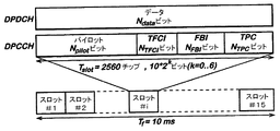
I/Q多重化されたDPDCHおよびDPCCHの連続データストリームは、等しい期間10msのフレームにフォーマットされる。DPDCH状態は各フレーム内では一定であるが、フレーム間では変化しうる。図3に、アップリンク専用物理チャネルのこのようなフレーム構造を示す。
【0038】
この例示的なフレーム構造を用いて、本発明のアプローチは、DPCCHにおいてオプションとして送信されるTFCIビットの特定の性質を活用して、パイロットビットの個数を増大させる(詳細は後述)。
【0039】
図3からわかるように、固定長の1ブロック内のデータフォーマットを規定し、基本伝送単位として作用する各フレームは、15個のスロットにさらに分割される。各DPCCHスロットには10個のシンボルがある。スロットあたりのDPDCHシンボルの個数は、DPDCH状態に依存する。それぞれのアップリンクDPCCHフィールドのシンボルの個数(Npilot、NTPC、NFBI、およびNTFCI)は、アップリンクモードに依存し、1つのアップリンクの継続時間中は固定される。例示的なモードとして、可能な組合せが、図4に示すテーブルに列挙されている。明らかに、パイロットブロックの長さNpilotは、スロットあたり5〜8ビットの間で変化しうる。
【0040】
さらに、前述のように、TFCは、各エントリが1つのDPDCH状態を表すようなルックアップテーブルとして理解される。これに基づいて、トランスポートフォーマットコンビネーションインジケータTFCIは、そのTFCルックアップテーブルへのポインタとして理解することができる。したがって、これは、同じフレームにおけるDPDCH状態について受信機に通知する。TFCルックアップテーブル内の各エントリごとに、1つのTFCIが存在する。ルックアップテーブルの長さに依存して、TFCIは、高々10ビットで表現することができる。ロバストな伝送を保証するため、TFCIは、好ましくは、送信前にパンクチャド・リード・マラー符号でブロック符号化される。すなわち、当業者に知られているように、各TFCIは、長さ30ビットの1個の符号語にマッピングされる。これらのTFCI符号語のビットをTFCIビットという。図4のテーブルからわかるように、30個の符号化されたTFCIビットは、各フレームの15個のタイムスロット間で均等に、すなわち、スロットあたり2ビットずつに、分割される。リード・マラー符号で導入される冗長性により、いくつかのTFCIビットが誤って受信されたとしても、再構成、すなわち、送信されたTFCIの復号が可能となる。
【0041】
本発明で使用可能なリード・マラー符号化および復号の具体的な詳細は場合により異なり、一般に当業者に周知であるため、リード・マラー符号については以下の記述では詳細には説明しない。さらに、注意すべき点であるが、図4のテーブルに示される組合せは最終的ではなく、すでに現在でも他の可能なモードが存在する。例えば、Npilotが、スロットあたり最小数で3ビットの長さであり、NTFCIが、スロットあたり4ビットまでの長さであるようなモードがある。
【0042】
図4に基づいて、本発明は、TFCIが送信される場合に、パイロットビットの個数Npilotを2ビット増大させて、スロットあたり最小で7個のパイロットビットにする。
【0043】
しかし、受信機は通常、送信された各TFCIビットが受信されるときにそのバイナリ情報を知らないため、TFCIビット自体をパイロットビットとして使用することはできない。そのため、TFCIビットの以下の2つの性質が活用される。
【0044】
第1に、フレームあたり30個(すなわち、フレームあたり15個のスロットでスロットあたり2個)のTFCIビットが、パンクチャド・リード・マラー符号の1符号語を構成する。
【0045】
第2に、DPDCHの1フレームは、対応するDPCCHフレームのTFCI符号語が復号され、DPDCHフレームの性質がTFCルックアップテーブルから決定された後にのみ、逆拡散され処理されることが可能である。
【0046】
TFCI符号語の復号により1つの符号語が得られるが、その復号は正しいか誤っているかのいずれかである。
【0047】
TFCI符号語が誤って復号された場合、そのTFCI符号語に埋め込まれた情報を回復することはできない。しかし、TFCI復号アルゴリズムは、復号されたTFCIに誤りがないかどうかを判断することはできないため、システムは、得られたTFCIがこのフレームの正しいDPDCH状態を示しているかのように進行する。このため、誤ったチャネル化符号、レートマッチングあるいは多重化パラメータが、現在のDPDCHフレームに適用され、このDPDCHフレームの全データはその結果として失われることになる。この障害は、後続の巡回冗長検査(CRC)で検出される。その後、上位層機能が、このフレームが再送されるよう要求することになる。このような情報の損失は、実質的に、DPDCHのチャネル推定値の品質とは無関係に起こる。
【0048】
これに対して、TFCI符号語が正しく復号された場合、埋め込まれているTFCI情報が知られ、このフレームのDPDCH状態を正しく判定することができる。この場合、DPDCHのチャネル推定値が良くなると、BER(ビット誤り率)は低くなる。TFCIから対応するTFCIビットへの一意的なマッピングが存在するため、TFCIを受信機側で再符号化してこのフレームで送信されたTFCIビットを得ることができる。その結果、この場合は、各TFCIビットを、DPDCHのチャネル推定のための追加パイロットシンボルとして使用することができる。
【0049】
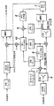
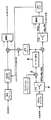
本発明のアプローチは、好ましくは、RAKEフィンガと呼ばれるL個の並列処理ユニットを含み、最大比合成MRC(maximal ratio combining)を適用する手段を有する例示的なRAKE受信機で実現される。本発明のアプローチを用いたRAKE受信機の1つのこのようなRAKEフィンガの概略図を図1に示す。これに対して、図5は、本発明のアプローチを用いていない従来技術によるRAKEフィンガを示す。
【0050】
RAKE受信機を使用するのが好ましいのは、WCDMAシステムに適用可能な通常のチャネルモデルは離散的な広義定常無相関散乱(WSSUS:wide sense stationary uncorrelated scattering)チャネルモデルであり、その場合、受信信号は、入力信号の遅延レプリカに、独立のゼロ平均複素ガウス時変過程で重みづけしたものの和によって表現されるからである。
【0051】
具体的には、x(t)およびy(t)でそれぞれチャネル入力および出力の等価な複素ベースバンド表現を表す場合、次式のようになる。
【数1】

【0052】
RAKE受信機に基づく受信フィルタを適用し、RAKE受信機の1つのマルチパスに対応する1つのRAKEフィンガにおけるDPCCHに対するデスクランブリングおよび逆拡散の後に、得られる離散信号は、次の形に書くことができる。
yl,DPCCH(m)=hl(m)xDPCCH(m)+n(m)
yl,DPDCH(m)=hl *(m)xDPDCH(m)+n(m) (2)
ただし、xDPCCH(m)およびxDPDCH(m)は、前述のように、それぞれDPCCHおよびDPDCHのBPSKシンボルストリームである。信号n(m)は、等価白色ガウス雑音源を表す。
【0053】
受信機の1つの目的は、受信されたyDPCCH(m)およびyDPDCH(m)からxDPCCH(m)およびxDPDCH(m)を推定することである。この目的は通常、2つの主要な段階に分割される。第1段階は、hl(m)およびn(m)の効果を最小にするために、yDPCCH(m)およびyDPDCH(m)を処理する。この段階を前処理という。第2段階は、誤り訂正復号を利用して、もともと送信された2元シンボルストリームを推定する。
【0054】
最適な前処理は、次式を計算するものであることが確立されている。
【数2】
【0055】
この前処理を近似的に行うRAKE受信機の各RAKEフィンガは、式(3)の和の項のうちの1つを計算する。ただし、式(3)は、チャネル伝達関数hl(m)がl番目のRAKEフィンガで既知であることを要求している。ここで、hl(m)を推定するためのさまざまな技術がこれまで提案されている。
【0056】
比較のために図5を参照すると、従来技術によるRAKEフィンガの可能な実現例が示されている。従来技術の受信機は、パイロット支援法と呼ばれる最もふつうのクラスのチャネル推定アルゴリズムのうちの1つを利用する。これは、受信機に事前に既知である送信されたパイロットシンボルに基づくチャネル推定アルゴリズムである。
【0057】
図5による受信機は、受信データから既知のパイロットビットを取り出すことが可能である。こうして受信機は、加法性雑音によって劣化した伝送チャネルの観測値を得る。WCDMAシステムにおけるチャネル伝達関数hl(m)は、シンボルレートでサンプリングされるとき狭帯域信号であるため、チャネル推定値は、何らかの形のローパスフィルタリングによって改善することができる。
【0058】
図示のRAKEフィンガの構造は、例示的な3GPPアップリンクの特定の性質、すなわち、パイロットビットがDPCCH内の他の制御情報と多重化されることを考慮に入れている。図5のユニット4によって、パイロットビット位置にある受信データの部分を他の制御ビット位置にある部分から分離した後、パイロットビット情報は、各スロットに対する既知のパイロットパターンを用いて、簡単な乗算5によって取り出される。結果として得られる信号は、チャネルの実際の観測値であり、チャネル推定デバイス6に供給される。チャネルエスティメータ6のための具体的なアルゴリズムは、当業者には知られているように個々のシステム制約に適応されるが、本発明にとっては重要でない。図5に示されるように、DPDCHの1フレーム分の遅延は、フレーム全体が受信された後にしか復号することができないTFCIビットによるものである。図5による従来のRAKE受信機の構造に基づいて、本発明のアプローチを含む改善されたRAKE受信機のRAKEフィンガを図1に示す。ここで、図5と類似または同等の作用手段は同じ参照符号で示される。図1による本発明の受信機は、図5による従来のRAKE受信機と比較して、次のように作用する。
【0059】
各DPCCHフレームの最後に、フレームの30個のTFCIビットが復号され、最尤送信TFCIが決定される。修正された復号デバイス7は、DPDCHフレームを処理するためのDPDCH状態パラメータのみならず、得られたTFCIをも出力する。
【0060】
次に、TFCIは、TFCI符号器8に供給される。TFCI符号器8は、送信機側、例えば、移動局内で使用されるTFCI符号器と同一であり、3GPP標準で規定される。TFCI符号器8は、このTFCIに対応する30個のTFCIビットを出力する。
【0061】
次に、得られたTFCIビットは、乗算9において、受信データからTFCIビット情報を取り出すために使用される。この操作は、前述のパイロットデータの取り出しプロセス5に比せられる。
【0062】
次に、得られたデータは、第2チャネル推定デバイス10に供給される。第2チャネル推定デバイス10への他の入力は、このDPCCHフレームのパイロット情報や、第1チャネル推定デバイス6からのチャネル推定値であることが可能である。第2チャネル推定デバイス10に供給される新たなチャネル推定値は、DPDCHデータストリームを補償するために使用される。
【0063】
前述のように、TFCIが誤って復号された場合、TFCIビット情報は受信データから正しく取り出されない。その結果、第2チャネル推定ブロックによって生成されるチャネル推定値の品質は劣化し、実際には、第1チャネルエスティメータからのものより悪くなる可能性もある。
【0064】
これに対して、TFCIが正しく復号された場合、パイロットビットから、および、TFCIビットから第2チャネルエスティメータ10への入力と、計算されるチャネル推定値の品質との間には質的な差はなく、あたかもシステムにパイロットビットを追加したかのようになる。
【0065】
この改善されたチャネル推定方式の追加的な数値的複雑さ(計算量)は小さく抑えることができる。TFCI符号化手段8は、簡単なルックアップテーブルとして実現可能であるため、数値的複雑さおよび遅延は無視できる。第2チャネルエスティメータ10は、以下のようなさまざまな方法で設計可能である。
【0066】
第1の方法によれば、完全に新たなチャネル推定値を、初期パイロットシンボルと、TFCIビットから新たに生成されたチャネル情報とから計算する。しかし、このアプローチは、計算量が大きい。
【0067】
このため、本発明の図1の好ましい実施例によれば、第1チャネル推定手段6からのチャネル推定値は、TFCI処理からの追加データを用いることによって改善される。ほとんどのチャネル推定法は線形演算であるため、更新アルゴリズムは容易に設計することができる。さらに、第1および第2のチャネル推定デバイス6および10は、それらの全体の複雑さが、8個のパイロットビットに対する同等のチャネルエスティメータより大きくならないように設計することができる。
【0068】
【発明の効果】
このように、本発明によれば、DPDCHを補償するためのチャネル推定値は、いくつかの重要な場合に改善される。したがって、DPCCHビットのエネルギーを同じままに維持しなければならない場合でも、ある目標BERを受信機で得るために、DPDCHあたりの送信エネルギーを低減することができる。DPDCHにおける送信エネルギーのこの低減は、送信機側で、対応して図2のファクタβdを低減することによって達成される。前に指摘したように、送信エネルギーの低減は干渉の減少につながり、その結果、システム全体の容量が増大し、さらに、移動端末の電池寿命が長くなる。
【0069】
注意すべき点であるが、以上では主にアップリンクについて、好ましい実施例に関して本発明の説明をしたが、当業者には明らかなように、本発明は、ダウンリンクでも使用可能であり、具体的なシステム制約に依存した変形が、本発明の保護範囲から離れることなく可能である。
【0070】
特許請求の範囲の発明の要件の後に括弧で記載した番号は、本発明の一実施例の対応関係を示すもので本発明の範囲を限定するものと解釈すべきではない。
【図面の簡単な説明】
【図1】TFCIビットを追加パイロットビットとして使用する3GPPアップリンクのための受信機のRAKEフィンガを示す概略図である。
【図2】アップリンクにおける専用物理チャネルのための例示的な変調器を示す概略図である。
【図3】アップリンクにおけるDPDCHおよびDPCCHのフレーム構造を示す図である。
【図4】DPCCHフィールドの可能な組合せを有する例示的なモードを示す図である。
【図5】従来技術による、純粋にパイロット支援チャネル推定のみを使用する、3GPPアップリンクのための受信機のRAKEフィンガを示す概略図である。
【符号の説明】
1,2 拡散器
6 第1チャネル推定デバイス(第1チャネルエスティメータ)
8 TFCI符号器
10 第2チャネル推定デバイス(第2チャネルエスティメータ)[0001]
BACKGROUND OF THE INVENTION
The present invention relates to a method for receiving a signal according to the 3GPP CDMA standard and a receiver for receiving a signal according to the 3GPP CDMA standard.
[0002]
[Prior art]
As is known, in a multiple access communication system, multiple individual links (ie, exchange of information (eg, data) between multiple different sources (sources) and one or more different destinations. Therefore, any medium (for example, a dedicated connection via electromagnetic waves) provided between the two devices can coexist. Accordingly, such a communication system must be designed to minimize interference between links so that transmission information of individual links can be obtained at the receiver side. Some multiple access technologies for wireless communication systems, for example, by assigning non-overlapping time slots to each link (time division multiple access) or by assigning non-overlapping frequency bands to each link ( Frequency division multiple access), a technology for separating links, has been devised in the last few decades.
[0003]
Third generation systems, in particular mobile communication systems according to the 3rd Generation Partnership Project (3GPP) standard, use wideband CDMA (Code Division Multiple Access) technology for data transmission. On the transmitter side, user data is information source coded for transmission error protection. Usually, the transmission channel between the transmitter and the receiver causes considerable distortion of the transmitted signal and signal degradation due to additive noise. Therefore, in order to minimize the bit error rate after decoding on the receiver side, it is necessary to estimate and compensate the channel characteristics at the receiver to minimize the influence.
[0004]
Since the transmission channel is time-varying, channel estimation must be performed continuously. To facilitate channel estimation, pilot blocks, i.e. blocks of data symbols previously known by the receiver, may be transmitted on a particular control channel at regular intervals within a link. This is performed, for example, in the data stream in the uplink direction from the mobile station to the base station of the mobile communication system according to the 3GPP standard.
[0005]
In general, the higher the ratio of pilot symbols to non-pilot symbols in such a control channel, the better the channel estimate. This reduces the bit error rate (BER), which means that there are fewer data blocks that need to be retransmitted or that the transmission power can be reduced.
[0006]
However, according to the 3GPP standard, the number of pilot bits is fixed by this standard and depends on the link mode, such as uplink mode or downlink mode. For example, the structure of a so-called DPCCH (Dedicated Physical Control Channel) that transmits physical layer control information between two different devices in the system may change in each uplink mode and is embedded in it Since the number of pilot symbols can vary between a minimum and maximum number, the quality of the channel estimate obtained with the pilot assisted channel estimator also depends on the respective uplink mode of the system. In order to compensate for the degradation of the quality of the channel estimate when fewer pilot symbols are transmitted, it is necessary to increase the power of the transmitted signal. However, in a CDMA system, each link causes interference on all other links in the same cell, so unfortunately, an increase in transmit power increases the overall interference level, thereby adversely affecting the overall capacity of the system. Produce.
[0007]
Improvement of the channel estimate may be realized by applying a so-called data assisted channel estimation method. As is known, this generic class of algorithms is applicable to transmission systems that require channel information at the receiver side. However, the data support channel estimator is an iterative procedure. First, the channel estimate is approximated. Next, based on these estimated values, data included in the received signal is compensated, and a transmission data symbol stream is estimated. These estimated symbols usually contain errors, but they are assumed to be correct to be used as pilot bits in the second iteration.
[0008]
Thus, if the number of errors is sufficiently small, the newly calculated channel estimate is improved, so that the new estimate of the transmitted data contains fewer bit errors. These iterations can be repeated until the channel estimate and the estimated data sequence converge to a final estimate. Thus, in terms of estimation quality, the data support method may be superior to a pure pilot support (using only pilot) estimator. Ideally, the entire signal acts as a pilot symbol.
[0009]
[Problems to be solved by the invention]
On the other hand, if the initial estimate contains too many bit errors, the iterations can diverge.
[0010]
Furthermore, with respect to implementation, the data assisted estimation method has at least the following drawbacks.
[0011]
Each iteration introduces additional delay into the system, which is problematic in communication systems with tight total delay constraints.
[0012]
In addition, the additional delay requires an additional buffer, which is usually a significant drawback in systems that operate at high data rates and serve multiple users simultaneously.
[0013]
Furthermore, the computational complexity (computation) of the data support method tends to be significantly higher than that of a pure pilot support estimator. Usually, the computational complexity increases at least linearly with the number of iterations. However, the increase in computational complexity directly affects the required hardware and firmware complexity, and consequently the product cost.
[0014]
On the other hand, in the design of hardware and firmware for receivers incorporated in base stations and mobile stations of wireless communication systems that comply with the 3GPP standard, one of the main limitations is that the amount of calculation of the channel estimation algorithm is small. is there.
[0015]
Therefore, the advanced data support method has no choice and the pure pilot support method is used in connection with the above problems.
[0016]
The object of the present invention is to provide an improved mechanism for improving the quality of channel estimation in CDMA systems, in particular systems according to the 3GPP standard, while at the same time ensuring low complexity.
[0017]
[Means for Solving the Problems]
The solution of the present invention is realized by a method, receiver and implementation software having the characterizing features of
[0018]
That is, the present invention provides and utilizes a technique for improving pilot-based channel estimation by exploiting the specific nature of the structure according to the 3GPP standard, and particularly relates to a mode using control symbols.
[0019]
Channel estimation because the use of coded control symbols as additional pilot symbols for reception of signals encoded according to the 3GPP wideband CDMA standard increases the amount of symbols used as pilot symbols. Is improved. As a result, the capacity of the entire communication system is increased, energy required for transmission can be reduced, and the battery life of the mobile terminal is increased.
[0020]
According to a preferred embodiment, it is proposed to use coded control symbols transmitted on a dedicated physical control channel (DPCCH) of a 3GPP wideband CDMA transmission channel.
[0021]
Advantageously, the coded control symbols include data from a dedicated physical control channel (DPCCH) transport format combination indicator (TFCI). The reason is that there is a unique mapping from TFCI to the corresponding TFCI bit. The TFCI can be re-encoded at the receiver site to obtain transmitted TFCI bits that are used as additional pilot symbols for DPDCH channel estimation.
[0022]
Preferably, the invention is implemented in a RAKE receiver and comprises means for re-encoding the decoded control symbols and using the re-encoded control symbols as additional pilot symbols, which means TFCI encoder including.
[0023]
Furthermore, it is proposed that said means for re-encoding the decoded control symbols is associated with a channel estimation unit.
[0024]
Furthermore, it is proposed that the TFCI bits are decoded at the end of each DPCCH frame and the maximum likelihood transmission (most likely transmitted) TFCI is determined and re-encoded for use as an additional pilot symbol. .
[0025]
Further, the estimation of the characteristics of the 3GPP wideband CDMA transmission channel is based on the transmitted pilot symbols and the additional pilot symbols, and the estimation of the characteristics is preferably a dedicated physical data channel (DPDCH) characteristic. Is an estimate.
[0026]
According to another preferred embodiment, the estimation is based on transmitted pilot symbols and said additional pilot symbols, using pilot and data support channel estimation, or a transmitter (e.g. a base transmitter station transmitter). ) And a receiver (eg, a mobile station receiver).
[0027]
In this way, additional pilot bits are used to channel in the system by exploiting the specific structure of the control channel in the 3GPP uplink or downlink to generate additional pilot symbols for pilot assisted channel estimation. The channel estimate for compensation can be improved.
[0028]
Furthermore, since the present invention does not include an iterative algorithm, there is little additional delay or additional uncertainty introduced into the system, and the amount of additional computation is very small.
[0029]
Thus, the overall performance is predictable and the quality of the channel estimate is comparable to that obtained with two additional pilot bits.
[0030]
DETAILED DESCRIPTION OF THE INVENTION
To more readily understand the present invention, reference is first made to FIG. FIG. 2 shows, by way of example, only a modulator for a dedicated physical channel in the uplink of a mobile communication system according to the 3GPP standard using CDMA technology, in particular WCDMA (Wideband Code Division Multiple Access) for data transmission. FIG.
[0031]
As is known to those skilled in the art, CDMA technology, particularly used in multiple access communication systems according to the 3GPP standard, is ideal for transmitting signals rather than by assigning non-overlapping time slots and frequency bands to each link. In some cases, it is designed to achieve the separability of information on different links by introducing orthogonal redundancy. Therefore, the transmission information of one link can be separated from the transmission information of all other links by projecting the received signal onto a set of basis functions corresponding to this link.
[0032]
The operation of introducing redundancy is called diffusion. In this operation, each symbol of the logical transmission channel is modulated with a so-called channelization code. The channelization code is unique to this data stream and is known to the receiver. All channelization codes are orthogonal to each other. The operation of detection (detection) and separation is called despreading. In this operation, the received signal is correlated with the channelization code corresponding to the link of interest. Due to the orthogonality of the channelization codes, the transmitted signals on all other links are mostly suppressed resulting in a noise floor. This is called interference noise.
[0033]
In the exemplary uplink according to the 3GPP standard shown in FIG. 1, there are two types of uplink dedicated physical channels: uplink dedicated physical data channel DPDCH and uplink dedicated physical control channel DPCCH. In the following description, the bitstreams of these two channels are respectively xDPDCH(M) and xDPCCHIt will be represented by (m). These are BPSK (Binary Phase Shift Keying) streams, whose index m is based on a specific discrete time domain. The data rate on the DPCCH is fixed by the 3GPP standard, but the data rate on the DPDCH is determined at the time of link setup and can change dynamically during transmission in some uplink modes. As shown in FIG. 2, DPDCH and DPCCH are spread with different channelization codes by
[0034]
In the uplink, dedicated data (for example, telephone conversation data) generated in an upper layer (layer) is passed to
[0035]
The set of all allowed DPDCH states for a particular DPDCH is negotiated by higher layer functions between the two devices assigned to the system. That is, in the preferred embodiment, this negotiation takes place between a mobile terminal (eg, a cellular telephone) and a base station when a link is established between them and when a new transport channel is added. Is called. This set is called a transport format combination (TFC) and can be understood as a lookup table in which each entry represents one DPDCH state.
[0036]
The uplink DPCCH is used for transmitting control information generated in
[0037]
The I / Q multiplexed DPDCH and DPCCH continuous data streams are formatted into 10 ms frames of equal duration. The DPDCH state is constant within each frame but can change between frames. FIG. 3 shows such a frame structure of the uplink dedicated physical channel.
[0038]
Using this exemplary frame structure, the inventive approach takes advantage of the specific nature of the TFCI bits that are optionally transmitted on the DPCCH to increase the number of pilot bits (details below).
[0039]
As can be seen from FIG. 3, each frame that defines the data format in one fixed-length block and acts as a basic transmission unit is further divided into 15 slots. There are 10 symbols in each DPCCH slot. The number of DPDCH symbols per slot depends on the DPDCH state. Number of symbols in each uplink DPCCH field (Npilot, NTPC, NFBIAnd NTFCI) Depends on the uplink mode and is fixed for the duration of one uplink. As an exemplary mode, possible combinations are listed in the table shown in FIG. Obviously, the pilot block length NpilotCan vary between 5 and 8 bits per slot.
[0040]
Furthermore, as described above, the TFC is understood as a lookup table where each entry represents one DPDCH state. Based on this, the transport format combination indicator TFCI can be understood as a pointer to its TFC lookup table. This therefore informs the receiver about the DPDCH state in the same frame. There is one TFCI for each entry in the TFC lookup table. Depending on the length of the lookup table, the TFCI can be represented with at most 10 bits. To ensure robust transmission, the TFCI is preferably block coded with a punctured Reed-Muller code before transmission. That is, as known to those skilled in the art, each TFCI is mapped to one codeword of 30 bits in length. The bits of these TFCI code words are called TFCI bits. As can be seen from the table of FIG. 4, the 30 encoded TFCI bits are divided evenly between the 15 time slots of each frame, ie, 2 bits per slot. The redundancy introduced in the Reed-Muller code allows reconfiguration, i.e. decoding of the transmitted TFCI, even if some TFCI bits are received in error.
[0041]
Since the specific details of Reed-Muller encoding and decoding that can be used in the present invention vary from case to case and are generally well known to those skilled in the art, Reed-Muller codes are not described in detail in the following description. Furthermore, it should be noted that the combinations shown in the table of FIG. 4 are not final and there are already other possible modes. For example, NpilotIs a minimum of 3 bits long per slot and NTFCIHowever, there are modes where the length is up to 4 bits per slot.
[0042]
Based on FIG. 4, the present invention relates to the number N of pilot bits when TFCI is transmitted.pilotIs increased by 2 bits to a minimum of 7 pilot bits per slot.
[0043]
However, since the receiver typically does not know the binary information when each transmitted TFCI bit is received, the TFCI bit itself cannot be used as a pilot bit. Therefore, the following two properties of the TFCI bit are utilized.
[0044]
First, 30 TFCI bits per frame (ie, 15 slots per frame and 2 per slot) constitute one codeword of the punctured Reed-Muller code.
[0045]
Second, one frame of DPDCH can be despread and processed only after the TFCI codeword of the corresponding DPCCH frame is decoded and the properties of the DPDCH frame are determined from the TFC lookup table.
[0046]
One codeword is obtained by decoding the TFCI codeword, but the decoding is either correct or incorrect.
[0047]
If a TFCI code word is decoded in error, the information embedded in that TFCI code word cannot be recovered. However, since the TFCI decoding algorithm cannot determine if the decoded TFCI is error free, the system proceeds as if the resulting TFCI indicates the correct DPDCH state for this frame. Thus, incorrect channelization codes, rate matching or multiplexing parameters are applied to the current DPDCH frame and all data in this DPDCH frame will be lost as a result. This failure is detected by a subsequent cyclic redundancy check (CRC). The upper layer function will then request that this frame be retransmitted. Such loss of information occurs substantially independent of the quality of the DPDCH channel estimate.
[0048]
On the other hand, when the TFCI code word is correctly decoded, the embedded TFCI information is known, and the DPDCH state of this frame can be correctly determined. In this case, the BER (bit error rate) decreases as the DPDCH channel estimation value improves. Since there is a unique mapping from the TFCI to the corresponding TFCI bit, the TFCI bit transmitted in this frame can be obtained by re-encoding the TFCI at the receiver side. As a result, in this case, each TFCI bit can be used as an additional pilot symbol for DPDCH channel estimation.
[0049]
The inventive approach is preferably implemented in an exemplary RAKE receiver that includes L parallel processing units, called RAKE fingers, and has means to apply maximum ratio combining (MRC). A schematic diagram of one such RAKE finger of a RAKE receiver using the inventive approach is shown in FIG. In contrast, FIG. 5 shows a prior art RAKE finger that does not use the approach of the present invention.
[0050]
Preferably, a RAKE receiver is used, and a typical channel model applicable to a WCDMA system is a discrete wide sense stationary uncorrelated scattering (WSSUS) channel model, in which case the received signal This is because it is expressed by the sum of the delayed replica of the input signal weighted by an independent zero-mean complex Gaussian time-varying process.
[0051]
Specifically, when x (t) and y (t) represent equivalent complex baseband representations of channel input and output, respectively, the following equation is obtained.
[Expression 1]
[0052]
After applying a receive filter based on a RAKE receiver and descrambling and despreading the DPCCH in one RAKE finger corresponding to one multipath of the RAKE receiver, the resulting discrete signal can be written in the form it can.
yl, DPCCH(M) = hl(M) xDPCCH(M) + n (m)
yl, DPDCH(M) = hl *(M) xDPDCH(M) + n (m) (2)
Where xDPCCH(M) and xDPDCH(M) is a BPSK symbol stream of DPCCH and DPDCH, respectively, as described above. The signal n (m) represents an equivalent white Gaussian noise source.
[0053]
One purpose of the receiver is to receive yDPCCH(M) and yDPDCH(M) to xDPCCH(M) and xDPDCH(M) is estimated. This purpose is usually divided into two main stages. The first stage is hlTo minimize the effects of (m) and n (m), yDPCCH(M) and yDPDCHProcess (m). This stage is called preprocessing. The second stage uses error correction decoding to estimate the originally transmitted binary symbol stream.
[0054]
It has been established that the optimal preprocessing is to calculate
[Expression 2]
[0055]
Each RAKE finger of the RAKE receiver that approximately performs this preprocessing calculates one of the sum terms in equation (3). However, the equation (3) is the channel transfer function hl(M) is required to be known at the l-th RAKE finger. Where hlVarious techniques for estimating (m) have been proposed so far.
[0056]
Referring to FIG. 5 for comparison, a possible implementation of a prior art RAKE finger is shown. Prior art receivers utilize one of the most common classes of channel estimation algorithms called pilot assistance methods. This is a channel estimation algorithm based on transmitted pilot symbols that are known in advance to the receiver.
[0057]
The receiver according to FIG. 5 can extract known pilot bits from the received data. In this way, the receiver obtains observations of the transmission channel that have been degraded by additive noise. Channel transfer function h in WCDMA systemlSince (m) is a narrowband signal when sampled at the symbol rate, the channel estimate can be improved by some form of low-pass filtering.
[0058]
The illustrated RAKE finger structure takes into account the particular nature of the exemplary 3GPP uplink, ie that the pilot bits are multiplexed with other control information in the DPCCH. After separating the portion of the received data at the pilot bit positions by the unit 4 of FIG. 5 from the portions at the other control bit positions, the pilot bit information is simply multiplied 5 using a known pilot pattern for each slot. Is taken out by. The resulting signal is the actual observation of the channel and is supplied to the
[0059]
At the end of each DPCCH frame, the 30 TFCI bits of the frame are decoded to determine the maximum likelihood transmission TFCI. The modified
[0060]
The TFCI is then supplied to the
[0061]
The obtained TFCI bits are then used in multiplication 9 to extract TFCI bit information from the received data. This operation is compared with the pilot
[0062]
Next, the obtained data is supplied to the second
[0063]
As described above, when the TFCI is decoded in error, the TFCI bit information is not correctly extracted from the received data. As a result, the quality of the channel estimate generated by the second channel estimation block is degraded and may actually be worse than that from the first channel estimator.
[0064]
On the other hand, if the TFCI is decoded correctly, there is a qualitative difference between the pilot bits and from the input to the
[0065]
The additional numerical complexity (computation) of this improved channel estimation scheme can be kept small. Since the TFCI encoding means 8 can be realized as a simple look-up table, numerical complexity and delay can be ignored. The
[0066]
According to the first method, a completely new channel estimate is calculated from the initial pilot symbols and the channel information newly generated from the TFCI bits. However, this approach is computationally intensive.
[0067]
Thus, according to the preferred embodiment of FIG. 1 of the present invention, the channel estimate from the
[0068]
【The invention's effect】
Thus, according to the present invention, the channel estimate for compensating DPDCH is improved in several important cases. Therefore, even if the energy of the DPCCH bits must be kept the same, the transmission energy per DPDCH can be reduced in order to obtain a certain target BER at the receiver. This reduction in transmission energy on the DPDCH corresponds to the factor β in FIG.dIs achieved by reducing. As pointed out earlier, a reduction in transmission energy leads to a reduction in interference, resulting in an increase in overall system capacity and a longer mobile terminal battery life.
[0069]
It should be noted that although the present invention has been described above with reference to the preferred embodiment, primarily for the uplink, it will be apparent to those skilled in the art that the present invention can also be used in the downlink and is Variations depending on general system constraints are possible without departing from the scope of protection of the present invention.
[0070]
The numbers in parentheses after the requirements of the claimed invention indicate the correspondence of one embodiment of the present invention and should not be construed as limiting the scope of the present invention.
[Brief description of the drawings]
FIG. 1 is a schematic diagram of a receiver RAKE finger for 3GPP uplink using TFCI bits as additional pilot bits.
FIG. 2 is a schematic diagram illustrating an example modulator for a dedicated physical channel in the uplink.
FIG. 3 is a diagram illustrating a frame structure of DPDCH and DPCCH in the uplink.
FIG. 4 shows an exemplary mode with possible combinations of DPCCH fields.
FIG. 5 is a schematic diagram of a receiver RAKE finger for 3GPP uplink using purely pilot assisted channel estimation according to the prior art;
[Explanation of symbols]
1, 2 diffuser
6 First channel estimation device (first channel estimator)
8 TFCI encoder
10 Second channel estimation device (second channel estimator)
Claims (11)
符号化された制御シンボル(TFCI)が追加パイロットシンボルとして使用され、伝送された各トランスポートフォーマットコンビネーションインジケータ(TFCI)ビットが復号され、追加パイロットシンボルとしての使用のために再符号化される方法。In a method for receiving a signal encoded according to the 3GPP wideband CDMA standard,
Coded control symbols (TFCI) are used as additional pilot symbols are decoded each transport format combination indicator (TFCI) bits transmitted, how to be re-encoded for use as additional pilot symbols .
符号化された制御シンボルを追加パイロットシンボルとして使用する手段(7,8,9,10)を有し、
復号された制御シンボルを再符号化し、該再符号化された制御シンボルを追加パイロットシンボルとして使用し、TFCI符号器(8)を有する手段(8,9,10)を有する受信機。In a receiver that receives a signal encoded according to the 3GPP wideband CDMA standard,
Have a means (7, 8, 9, 10) for using coded control symbols as additional pilot symbols,
Then re-encodes the decoded control symbols, using該再coded control symbols as additional pilot symbols, receiver device that having a means (8, 9, 10) having TFCI encoder (8).
Applications Claiming Priority (2)
| Application Number | Priority Date | Filing Date | Title |
|---|---|---|---|
| EP01304707.1 | 2001-05-29 | ||
| EP01304707A EP1263179B1 (en) | 2001-05-29 | 2001-05-29 | Channel estimation for a CDMA system using coded control symbols as additional pilot symbols |
Publications (3)
| Publication Number | Publication Date |
|---|---|
| JP2003032146A JP2003032146A (en) | 2003-01-31 |
| JP2003032146A5 JP2003032146A5 (en) | 2005-09-08 |
| JP4017917B2 true JP4017917B2 (en) | 2007-12-05 |
Family
ID=8181993
Family Applications (1)
| Application Number | Title | Priority Date | Filing Date |
|---|---|---|---|
| JP2002147977A Expired - Fee Related JP4017917B2 (en) | 2001-05-29 | 2002-05-22 | Signal reception method |
Country Status (5)
| Country | Link |
|---|---|
| US (1) | US20020191578A1 (en) |
| EP (1) | EP1263179B1 (en) |
| JP (1) | JP4017917B2 (en) |
| KR (1) | KR100501617B1 (en) |
| DE (1) | DE60129111T2 (en) |
Families Citing this family (32)
| Publication number | Priority date | Publication date | Assignee | Title |
|---|---|---|---|---|
| JP3562502B2 (en) * | 2001-09-27 | 2004-09-08 | 日本電気株式会社 | CDMA receiver and channel estimation method for the same |
| EP1563627A4 (en) * | 2002-11-22 | 2009-11-04 | Interdigital Tech Corp | Channel gain estimation in a rake receiver using complex weight generation (cwg) algorithms |
| JP3742055B2 (en) * | 2002-11-27 | 2006-02-01 | 埼玉日本電気株式会社 | Radio base station apparatus, decoding apparatus using TFCI decoding characteristics used therein, and decoding method thereof |
| JP3776877B2 (en) * | 2002-12-04 | 2006-05-17 | 埼玉日本電気株式会社 | Mobile communication system, radio base station controller, and uplink reception synchronization determination method used therefor |
| US20040128607A1 (en) * | 2002-12-31 | 2004-07-01 | Ilan Sutskover | Method and apparatus to encode linear block codes |
| GB0302024D0 (en) * | 2003-01-29 | 2003-02-26 | Roke Manor Research | Transport format combination selection in the uplink for the flexible layer one |
| NZ524929A (en) | 2003-03-25 | 2005-11-25 | Ind Res Ltd | Method and apparatus for improving the performance of pilot symbol assisted receivers in the presence of narrowband interference |
| JP4258272B2 (en) | 2003-05-15 | 2009-04-30 | 日本電気株式会社 | CDMA receiver and its TFCI candidate determination method |
| EP1521413A3 (en) * | 2003-10-01 | 2009-09-30 | Panasonic Corporation | Multicarrier reception with channel estimation and equalisation |
| US7352829B2 (en) | 2004-01-12 | 2008-04-01 | Infineon Technologies Ag | Data-aided channel estimation |
| CN1926777A (en) * | 2004-03-24 | 2007-03-07 | 意大利电信股份公司 | Method and system for channel estimation, relating receiver and computer program product |
| US7706324B2 (en) * | 2004-07-19 | 2010-04-27 | Qualcomm Incorporated | On-demand reverse-link pilot transmission |
| US7924770B2 (en) * | 2004-08-06 | 2011-04-12 | Nokia Corporation | Method of controlling communication between two nodes in a communication system |
| CN100415036C (en) * | 2004-09-16 | 2008-08-27 | 华为技术有限公司 | Detecting method for upward intensified special channels |
| EP1811680A4 (en) * | 2004-10-15 | 2008-09-03 | Ntt Docomo Inc | Radio base station, radio line control station, mobile communication system, and mobile communication method |
| EP1807987A4 (en) | 2004-10-29 | 2012-11-07 | Ericsson Telefon Ab L M | Channel estimation |
| KR100927292B1 (en) * | 2005-02-03 | 2009-11-18 | 후지쯔 가부시끼가이샤 | Wireless communication system and wireless communication method |
| FI20055311A0 (en) * | 2005-06-15 | 2005-06-15 | Nokia Corp | Data sequence detection in a communication system |
| FI20055312A0 (en) * | 2005-06-15 | 2005-06-15 | Nokia Corp | Method and radio receiver for increasing the number of symbols used as pilot symbols in a communication system |
| US8493942B2 (en) * | 2005-08-01 | 2013-07-23 | Qualcomm Incorporated | Interference cancellation in wireless communication |
| ES2556112T3 (en) | 2005-08-16 | 2016-01-13 | Koninklijke Philips N.V. | Format adaptation of a control channel for discontinuous data transmission |
| KR100863791B1 (en) * | 2005-10-12 | 2008-10-17 | 삼성전자주식회사 | Transmiting/receiving apparatus and method for channel estimating using packet data control channel in a frequency division multiple access communication system and system thereof |
| KR100693555B1 (en) | 2005-12-09 | 2007-03-14 | 주식회사 팬택 | A channel estimation method to improve the performance of digital multimedia broadcasting receiver |
| WO2007068138A1 (en) * | 2005-12-12 | 2007-06-21 | Zte Corporation | A system and method for adjusting amplitude of the channel decoded data in cdma system |
| JP4899555B2 (en) * | 2006-03-17 | 2012-03-21 | 富士通株式会社 | Wireless communication system, transmitting apparatus and receiving apparatus |
| JP4531722B2 (en) * | 2006-05-01 | 2010-08-25 | 株式会社エヌ・ティ・ティ・ドコモ | User device, transmission method, and mobile communication system |
| WO2008024357A2 (en) * | 2006-08-24 | 2008-02-28 | Interdigital Technology Corporation | Power control for improving link reliability in hsdpa |
| KR100954818B1 (en) * | 2006-11-24 | 2010-04-28 | 삼성전자주식회사 | Apparatus and method for interference cancellation in broadband wireless communication system |
| WO2008099342A1 (en) | 2007-02-12 | 2008-08-21 | Nokia Corporation | Shared control channel data-assisted channel estimation |
| KR100914321B1 (en) | 2007-12-03 | 2009-08-27 | 한국전자통신연구원 | Method for enbodying frame in wideband wireless communication system using multi antennas |
| GB2482122B (en) * | 2010-07-19 | 2014-02-19 | Intellectual Ventures Holding 81 Llc | Communication unit and pilot method for time varying channels |
| US9614606B2 (en) | 2011-12-28 | 2017-04-04 | Qualcomm Incorporated | Method and apparatus for power aware receive diversity control |
Family Cites Families (11)
| Publication number | Priority date | Publication date | Assignee | Title |
|---|---|---|---|---|
| US5544156A (en) * | 1994-04-29 | 1996-08-06 | Telefonaktiebolaget Lm Ericsson | Direct sequence CDMA coherent uplink detector |
| JP3363734B2 (en) * | 1997-02-21 | 2003-01-08 | 沖電気工業株式会社 | Frequency control circuit |
| GB2330992A (en) * | 1997-11-03 | 1999-05-05 | Nokia Mobile Phones Ltd | Channel estimation in a variable data rate communication system |
| US6285663B1 (en) * | 1998-06-05 | 2001-09-04 | Telefonaktiebolaget Lm Ericsson (Publ) | Increasing performance in communications by embedding one signal in another signal |
| MY130820A (en) * | 1998-12-16 | 2007-07-31 | Ericsson Telefon Ab L M | Channel estimation for a cdma system using pre-defined symbols in addition to pilot symbols |
| US6452917B1 (en) * | 1999-04-08 | 2002-09-17 | Qualcomm Incorporated | Channel estimation in a CDMA wireless communication system |
| US6414988B1 (en) * | 1999-05-12 | 2002-07-02 | Qualcomm Incorporated | Amplitude and phase estimation method in a wireless communication system |
| EP1065800A1 (en) * | 1999-07-02 | 2001-01-03 | Lucent Technologies Inc. | Code division multiple access system having improved pilot channels |
| EP1067730A1 (en) * | 1999-07-02 | 2001-01-10 | Alcatel | Determining the transmission quality of a radio channel |
| JP4813723B2 (en) * | 1999-12-01 | 2011-11-09 | テレフオンアクチーボラゲット エル エム エリクソン(パブル) | Bit error rate estimation from pilot symbols |
| KR100663559B1 (en) * | 1999-12-31 | 2007-01-02 | 삼성전자주식회사 | Coherent demodulation apparatus and method in cdma communication system |
-
2001
- 2001-05-29 DE DE60129111T patent/DE60129111T2/en not_active Expired - Lifetime
- 2001-05-29 EP EP01304707A patent/EP1263179B1/en not_active Expired - Lifetime
-
2002
- 2002-04-29 US US10/134,082 patent/US20020191578A1/en not_active Abandoned
- 2002-05-22 JP JP2002147977A patent/JP4017917B2/en not_active Expired - Fee Related
- 2002-05-28 KR KR10-2002-0029503A patent/KR100501617B1/en not_active IP Right Cessation
Also Published As
| Publication number | Publication date |
|---|---|
| DE60129111D1 (en) | 2007-08-09 |
| JP2003032146A (en) | 2003-01-31 |
| DE60129111T2 (en) | 2008-02-28 |
| EP1263179B1 (en) | 2007-06-27 |
| KR100501617B1 (en) | 2005-07-18 |
| EP1263179A1 (en) | 2002-12-04 |
| KR20020090901A (en) | 2002-12-05 |
| US20020191578A1 (en) | 2002-12-19 |
Similar Documents
| Publication | Publication Date | Title |
|---|---|---|
| JP4017917B2 (en) | Signal reception method | |
| US7123645B2 (en) | Spread-spectrum signal receiver | |
| EP0993740B1 (en) | A subscriber unit and method for use in a wireless communication system | |
| JP3889038B2 (en) | Method and apparatus for controlling coding rate in a communication system | |
| US7142865B2 (en) | Transmit power control based on virtual decoding | |
| RU2262193C2 (en) | Method and system for controlling transmission energy in communication system of alternating speed with strobing | |
| WO2000045527A2 (en) | Method and apparatus for controlling transmission power in a cdma communication system | |
| US8315344B2 (en) | Blind detection of the transport format (TF) of a signal | |
| JPH11502098A (en) | Improved channel estimation in communication systems | |
| EP1198938A1 (en) | Fading resistant multi-level qam receiver | |
| JP2006507738A (en) | Method, apparatus and device for decoding communication signals | |
| WO2010108998A1 (en) | Estimation of signal and interference power | |
| JP3562502B2 (en) | CDMA receiver and channel estimation method for the same | |
| JP4756134B2 (en) | Decoding method and apparatus | |
| US7218667B2 (en) | Radio reception apparatus and radio reception method | |
| US7457379B2 (en) | Adaptive multi-step combined DC offset compensation for EDGE 8-PSK | |
| US7856071B2 (en) | Multi-path acquisition in the presence of very high data rate users | |
| WO2002039686A1 (en) | A channel estimating method and apparatus thereof | |
| JP2006165775A (en) | Radio base station equipment, radio transmitter/receiver and radio communication system | |
| WO2005006690A1 (en) | System, method and computer program product for demodulating quadrature amplitude modulated signals based upon a speed of a receiver | |
| WO2005004423A1 (en) | System, method and computer program product for demodulating quadrature amplitude modulated signals | |
| JP2001223621A (en) | Receiver | |
| KR20100019863A (en) | Method for restoring the received signal for multiple access system using user-specific interleavers | |
| KR20080060894A (en) | Method for controlling power of td-scdma system and apparatus applied to the same |
Legal Events
| Date | Code | Title | Description |
|---|---|---|---|
| A521 | Request for written amendment filed |
Free format text: JAPANESE INTERMEDIATE CODE: A523 Effective date: 20050310 |
|
| A621 | Written request for application examination |
Free format text: JAPANESE INTERMEDIATE CODE: A621 Effective date: 20050310 |
|
| A977 | Report on retrieval |
Free format text: JAPANESE INTERMEDIATE CODE: A971007 Effective date: 20070320 |
|
| A131 | Notification of reasons for refusal |
Free format text: JAPANESE INTERMEDIATE CODE: A131 Effective date: 20070509 |
|
| A521 | Request for written amendment filed |
Free format text: JAPANESE INTERMEDIATE CODE: A523 Effective date: 20070809 |
|
| TRDD | Decision of grant or rejection written | ||
| A01 | Written decision to grant a patent or to grant a registration (utility model) |
Free format text: JAPANESE INTERMEDIATE CODE: A01 Effective date: 20070827 |
|
| A61 | First payment of annual fees (during grant procedure) |
Free format text: JAPANESE INTERMEDIATE CODE: A61 Effective date: 20070919 |
|
| R150 | Certificate of patent or registration of utility model |
Free format text: JAPANESE INTERMEDIATE CODE: R150 |
|
| FPAY | Renewal fee payment (event date is renewal date of database) |
Free format text: PAYMENT UNTIL: 20100928 Year of fee payment: 3 |
|
| FPAY | Renewal fee payment (event date is renewal date of database) |
Free format text: PAYMENT UNTIL: 20100928 Year of fee payment: 3 |
|
| FPAY | Renewal fee payment (event date is renewal date of database) |
Free format text: PAYMENT UNTIL: 20110928 Year of fee payment: 4 |
|
| FPAY | Renewal fee payment (event date is renewal date of database) |
Free format text: PAYMENT UNTIL: 20110928 Year of fee payment: 4 |
|
| FPAY | Renewal fee payment (event date is renewal date of database) |
Free format text: PAYMENT UNTIL: 20120928 Year of fee payment: 5 |
|
| FPAY | Renewal fee payment (event date is renewal date of database) |
Free format text: PAYMENT UNTIL: 20120928 Year of fee payment: 5 |
|
| FPAY | Renewal fee payment (event date is renewal date of database) |
Free format text: PAYMENT UNTIL: 20130928 Year of fee payment: 6 |
|
| R250 | Receipt of annual fees |
Free format text: JAPANESE INTERMEDIATE CODE: R250 |
|
| R250 | Receipt of annual fees |
Free format text: JAPANESE INTERMEDIATE CODE: R250 |
|
| R250 | Receipt of annual fees |
Free format text: JAPANESE INTERMEDIATE CODE: R250 |
|
| R250 | Receipt of annual fees |
Free format text: JAPANESE INTERMEDIATE CODE: R250 |
|
| LAPS | Cancellation because of no payment of annual fees |