EP1065800A1 - Code division multiple access system having improved pilot channels - Google Patents
Code division multiple access system having improved pilot channels Download PDFInfo
- Publication number
- EP1065800A1 EP1065800A1 EP99305246A EP99305246A EP1065800A1 EP 1065800 A1 EP1065800 A1 EP 1065800A1 EP 99305246 A EP99305246 A EP 99305246A EP 99305246 A EP99305246 A EP 99305246A EP 1065800 A1 EP1065800 A1 EP 1065800A1
- Authority
- EP
- European Patent Office
- Prior art keywords
- channel
- pilot
- pilot symbols
- mobile
- dedicated
- Prior art date
- Legal status (The legal status is an assumption and is not a legal conclusion. Google has not performed a legal analysis and makes no representation as to the accuracy of the status listed.)
- Withdrawn
Links
Images


Classifications
-
- H—ELECTRICITY
- H04—ELECTRIC COMMUNICATION TECHNIQUE
- H04B—TRANSMISSION
- H04B7/00—Radio transmission systems, i.e. using radiation field
- H04B7/24—Radio transmission systems, i.e. using radiation field for communication between two or more posts
- H04B7/26—Radio transmission systems, i.e. using radiation field for communication between two or more posts at least one of which is mobile
-
- H—ELECTRICITY
- H04—ELECTRIC COMMUNICATION TECHNIQUE
- H04W—WIRELESS COMMUNICATION NETWORKS
- H04W52/00—Power management, e.g. TPC [Transmission Power Control], power saving or power classes
- H04W52/04—TPC
- H04W52/30—TPC using constraints in the total amount of available transmission power
- H04W52/32—TPC of broadcast or control channels
- H04W52/322—Power control of broadcast channels
-
- H—ELECTRICITY
- H04—ELECTRIC COMMUNICATION TECHNIQUE
- H04B—TRANSMISSION
- H04B1/00—Details of transmission systems, not covered by a single one of groups H04B3/00 - H04B13/00; Details of transmission systems not characterised by the medium used for transmission
- H04B1/69—Spread spectrum techniques
- H04B1/707—Spread spectrum techniques using direct sequence modulation
-
- H—ELECTRICITY
- H04—ELECTRIC COMMUNICATION TECHNIQUE
- H04L—TRANSMISSION OF DIGITAL INFORMATION, e.g. TELEGRAPHIC COMMUNICATION
- H04L25/00—Baseband systems
- H04L25/02—Details ; arrangements for supplying electrical power along data transmission lines
- H04L25/0202—Channel estimation
- H04L25/0212—Channel estimation of impulse response
-
- H—ELECTRICITY
- H04—ELECTRIC COMMUNICATION TECHNIQUE
- H04L—TRANSMISSION OF DIGITAL INFORMATION, e.g. TELEGRAPHIC COMMUNICATION
- H04L25/00—Baseband systems
- H04L25/02—Details ; arrangements for supplying electrical power along data transmission lines
- H04L25/0202—Channel estimation
- H04L25/0224—Channel estimation using sounding signals
- H04L25/0228—Channel estimation using sounding signals with direct estimation from sounding signals
-
- H—ELECTRICITY
- H04—ELECTRIC COMMUNICATION TECHNIQUE
- H04W—WIRELESS COMMUNICATION NETWORKS
- H04W52/00—Power management, e.g. TPC [Transmission Power Control], power saving or power classes
- H04W52/04—TPC
- H04W52/30—TPC using constraints in the total amount of available transmission power
- H04W52/32—TPC of broadcast or control channels
- H04W52/325—Power control of control or pilot channels
Definitions
- This invention relates to a code division multiple access (CDMA) system, especially a wide band or direct sequence (DS) CDMA system, and relates particularly to the arrangements for providing pilot channels.
- CDMA code division multiple access
- DS direct sequence
- a detection technique For effective use of direct sequence CDMA systems for digital mobile cellular telephone and personal communication network applications, a detection technique must be used which performs well at low signal to interference ratios. Coherent detection is preferred to non-coherent detection because it has better performance in the slow fading environments which typify personal communication channels. To apply coherent detection, the channel impulse response at a receiver must be known, and this can be achieved by transmitting pilot symbols.
- Pilot symbols can be transmitted in two ways; a) a dedicated pilot channel, i.e. one pilot channel for each user, in which pilot symbols are embedded periodically (time- or code-multiplexed) in the same channel as the data symbols, or b) a common pilot channel, i.e. one pilot channel for all users, in which pilot symbols are continuously sent on a separate channel in parallel with data channels.
- a dedicated pilot channel i.e. one pilot channel for each user, in which pilot symbols are embedded periodically (time- or code-multiplexed) in the same channel as the data symbols
- a common pilot channel i.e. one pilot channel for all users, in which pilot symbols are continuously sent on a separate channel in parallel with data channels.
- An advantage of dedicated pilot channels is that power can be varied, so that a mobile at a boundary of a cell can ramp up the power of its received symbols to overcome channel propagation as well as fast fading; however the system relies on good statistical multiplexing of users to ensure that there is always spare transmitter capacity to meet a sudden demand from a mobile for increased power, which can create instability.
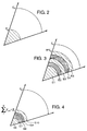
- Figure 1a shows the sector coverage angle alpha (e.g. 30° to 40°) over which a small base station transmits.
- Figure 1b indicates by the enclosed area the energy E d required to transmit data, and this is assumed to be constant.
- Figure 1c indicates by the shaded area the energy E p required to transmit pilot symbols in either a dedicated pilot channel or a common pilot channel.
- Figure 2 illustrates energy requirements in a common pilot channel arrangement, and is effectively a merger of figures 1b and 1c; a single continuous pilot channel is broadcast to all users.
- the total energy requirement for the pilot channels is N*E p . This arrangement assumes there is no power control facility to vary power transmission.
- Figure 4 shows a variation of figure 3 including a power control facility.
- the power supplied to each pilot channel can be controlled individually, as indicated by the different areas of the shaded and crosshatched bands E6 to E10.
- the pilot in a channel can even be switched off completely, saving energy, and allowing other data or control information to be transported by that channel.
- Pilot energy requirement is ⁇ E pj • ⁇ i where ⁇ i is the scaling factor for each user, dependant on power control and time multiplexing.
- ⁇ is between 1 and 0, i.e. it is small when a mobile is close to its base station.
- Figure 5 indicates energy requirements where spatially adaptive antennas are used.
- Data energy is transmitted in much narrower sections ⁇ 1 to ⁇ 4 within the sector angle ⁇ , i.e. a beam forming technique is used.
- the narrow sectors ⁇ 1 to ⁇ 4 are directed towards active mobiles, and the pilot energy required for each narrow sector is also varied in accordance with need, as indicated by the shaded areas. The total energy requirement is greatly reduced.
- the pilot energy requirement is ⁇ i E p G A where G A is the gain of the directed antennas.
- Figure 6 shows that, in addition to the directed channels of figure 5, some common channel facility is required across the whole sector angle ⁇ , e.g. for mobiles attempting to make a call, and the data power for this is indicated at E dc , between the directed sectors with the associated pilot energy indicated by the cross-hatched areas E pc . Pilot energy requirements are ⁇ i E p G A + ⁇ i E p , where C is the number of common channels.
- a method of providing pilot symbols comprises providing a first set of pilot symbols through a plurality of pilot channels, each such channel being dedicated to one mobile user; providing a second set of pilot symbols through at least one common control channel; and in a mobile combining the first and second sets of pilot symbols and providing said combination to channel impulse response sensing means.
- the common control dowmlink channel may be a broadcast channel or a forward access channel or a paging channel.
- a code division multiple access mobile radio telecommunications network comprising a plurality of mobiles each having a dedicated pilot channel; a plurality of base stations; first pilot symbol generation means arranged to supply pilot symbols to each dedicated pilot channel; second pilot symbol generation means arranged to supply to at least one common control channel dedicated pilot symbols embedded between data symbols broadcast by the common control channel; and in each mobile receiving means arranged to receive pilot symbols in the dedicated pilot channel and the common control channel, combining means to combine the received pilot symbols, channel estimation means to process the combined pilot symbols, and coherent detection means arranged to vary at least one property of the mobile in accordance with the output of the channel estimation means.
- a wireless telecommunication system 10 comprises a number of mobile stations (MS) 11,12,13,14 and a number of base transceiver stations N node B 15,16,17,18 connected through a radio network controller (RNC) 19,20 (all in the radio access network RAN 21) to a core network (CN) 22.
- the CN is connected to the public switched telephone network PSTN 23.
- each mobile 12 is provided with a dedicated pilot channel which carries pilot symbols to the mobile; the mobile uses these symbols to determine the extent of some of the key radio channel effects on desired transmitted signal to the mobile.
- the BCH is used to provide cell-specific information, such as the cell identity and the available short and long codes for random access channel RACH transmission; information about neighbouring cells can also be provided. In the majority of cell scenarios the information carried by the BCH can be assumed to be static for the duration of most telephone calls.
- the FACH is primarily used to carry initial call set-up control information to a mobile when the system knows the location cell of the mobile.
- the FACH can also carry short intermittent packet information.
- the PCH is used to carry information primarily to initiate network originated calls, eg from a landline telephone, to a mobile station when the system does not know the location cell of the mobile.
- the PCH may have a sleep mode when traffic is low.
- channelisation codes are separated from one another by channelisation codes, and possibly also be fixed time-offsets.
- each channel in addition has its own dedicated pilot symbols which are embedded at regular intervals between the transmitted data symbols.
- a mobile 12 utilises the pilot symbols in existing common downlink channels in addition to the pilot symbols provided by its own dedicated pilot channel or channels. By use of such a combination decreased energy is required in the dedicated pilot channel of the mobile.
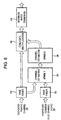
- FIG. 8 shows the energy flows.
- the pilot channel of the mobile 12 is referred to as a hybridised common pilot channel HCPC 30, and pilot information from it flows through a first rake finger 32 to a channel estimator in two stages 34, 36. Pilot information from at least one of the downlink channels, indicated at 38 as a dedicated traffic channel, passes through a second rake finger 40 to the channel estimators 34, 36. (Although two sets of rake fingers are shown, in practice only one may be needed).
- the output of the estimators 34, 36 passes to a conjugate multiplication stage 42 which also receives input directly from the dedicated traffic channel, and then to a maximum ratio combining stage 44.
- the output of the combining stage connected to the processor of the mobile, indicates channel impulse response of the mobile's receiver, and permits use within the mobile of coherent detection techniques.
- the channel estimation functional units 34,36 are shown in two stages to indicate the possibilities of:
- E p can be reduced.
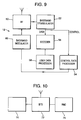
- a typical mobile 12 is shown in Figure 9. It has a RF transceiver 50 connected to a baseband demodulator 52 which passes control data to a control signal process of 54 and data signals to a decoder connected to a user data processor 58.
- a further reduction in pilot energy can be achieved by incorporation of base station (BTS) intervention.
- the mobile 12 is arranged to provide feedback signals to the BTS about the quality of its HCPCH, ie the noise or power or phaseb rotation of the pilot symbols.
- the BTS can then reduce the power of the pilot symbols in the mobile's dedicated pilot channel in comparison with the power of the data symbols.
- a further advantage of such a power variation is that, depending on the cell scenario, it will reduce the overall power transmitted by a BTS on the downlink, which for a multi-user CDMA system (Fig.7) improves the downlink capacity.
- control data processor provides the required information to the BTS by a loop to the base band demodulator 60 in the mobile, its output being connected to the RF transceiver 50.
- a yet further improvement is provided by adapting one of the common channels, using the BTS intervention arrangement described above.
- the channel and tracking estimation stages, 34, 36 in Figure 8 are arranged to estimate the performance gains from the HCPCH; this performance gain can be improved by adapting the time-offsets between the pilot symbols belonging to the common channel(s) being used to generate the HCPC and the pilot symbols transmitted on the dedicated traffic channel(s) to suit channel conditions.
- Such an arrangement affects a base station BTS; a typical arrangement is shown in Figure 10 in which a mobile 70 is connected to a BTS 72 which is controlled by a RNC 74.
- the RNC 74 controls the timing of the pilot symbols in the common channels which provide inputs as dedicated traffic channel energy in Figure 8, and can therefore vary the timing of the symbols with respect to the dedicated pilot channel symbols, as required.
- the RNC 74 can be arranged to substitute pilot symbols for data symbols on common channels such as the FACH or PCH to create Extended HCPC (EHCPC) channels. Doing this trades-off common channel capacity (eg the number of calls that can be set up or acknowledged in a unit of time) for improved channel estimation at a mobile.
- EHCPC Extended HCPC
- the mobile can use the effectively static data symbols ona common channel such as the BCH as pilot symbols to create EHCPC.
- a mobile must always listen to such a channel for new calls, or for a paging service message, and such channels are rarely congested.
Abstract
In a CDMA network, each mobile is arranged to combined
pilot symbols from its dedicated pilot channel with pilot
symbols from at least one common channel as an input to its
channel impulse response sensing means. The common channel
may be a BCH, a FACH or a PCH, and the pilot symbols on all
such channels may be combined. The pilot energy required on
each dedicated pilot channel can thereby be reduced. By
communicating the quality of the received pilot symbols to a
base station, the base station can reduce the energy on the
dedicated pilot channel, providing a yet further saving of
energy.
Description
- This invention relates to a code division multiple access (CDMA) system, especially a wide band or direct sequence (DS) CDMA system, and relates particularly to the arrangements for providing pilot channels.
- For effective use of direct sequence CDMA systems for digital mobile cellular telephone and personal communication network applications, a detection technique must be used which performs well at low signal to interference ratios. Coherent detection is preferred to non-coherent detection because it has better performance in the slow fading environments which typify personal communication channels. To apply coherent detection, the channel impulse response at a receiver must be known, and this can be achieved by transmitting pilot symbols.
- Pilot symbols can be transmitted in two ways; a) a dedicated pilot channel, i.e. one pilot channel for each user, in which pilot symbols are embedded periodically (time- or code-multiplexed) in the same channel as the data symbols, or b) a common pilot channel, i.e. one pilot channel for all users, in which pilot symbols are continuously sent on a separate channel in parallel with data channels.
- An advantage of dedicated pilot channels is that power can be varied, so that a mobile at a boundary of a cell can ramp up the power of its received symbols to overcome channel propagation as well as fast fading; however the system relies on goodstatistical multiplexing
 of users to ensure that there is always spare transmitter capacity to meet a sudden demand from a mobile for increased power, which can create instability.
- The well known differences between the two arrangements will now be described with reference to figures 1-6.
- Figure 1a shows the sector coverage angle alpha (e.g. 30° to 40°) over which a small base station transmits. Figure 1b indicates by the enclosed area the energy Ed required to transmit data, and this is assumed to be constant. Figure 1c indicates by the shaded area the energy Ep required to transmit pilot symbols in either a dedicated pilot channel or a common pilot channel.
- Figure 2 illustrates energy requirements in a common pilot channel arrangement, and is effectively a merger of figures 1b and 1c; a single continuous pilot channel is broadcast to all users.
- Figure 3 illustrates energy requirements in a dedicated pilot channel arrangement; each of the N users (where N = 5) has a different energy requirement E1 to E5, shown by the shaded and crosshatched areas. The total energy requirement for the pilot channels is N*Ep. This arrangement assumes there is no power control facility to vary power transmission.
- Figure 4 shows a variation of figure 3 including a power control facility. The power supplied to each pilot channel can be controlled individually, as indicated by the different areas of the shaded and crosshatched bands E6 to E10. At certain times, in theory, the pilot in a channel can even be switched off completely, saving energy, and allowing other data or control information to be transported by that channel. Pilot energy requirement is ΣEpj •β i where β i is the scaling factor for each user, dependant on power control and time multiplexing. β is between 1 and 0, i.e. it is small when a mobile is close to its base station.
- However comparison with figure 1c shows that the total power used is unchanged.
- Figure 5 indicates energy requirements where spatially adaptive antennas are used. Data energy is transmitted in much narrower sections α1 to α4 within the sector angle α, i.e. a beam forming technique is used. The narrow sectors α1 to α4 are directed towards active mobiles, and the pilot energy required for each narrow sector is also varied in accordance with need, as indicated by the shaded areas. The total energy requirement is greatly reduced. The pilot energy requirement isβi Ep GA where GA is the gain of the directed antennas.

- Figure 6 shows that, in addition to the directed channels of figure 5, some common channel facility is required across the whole sector angle α, e.g. for mobiles attempting to make a call, and the data power for this is indicated at Edc, between the directed sectors with the associated pilot energy indicated by the cross-hatched areas Epc. Pilot energy requirements areβi Ep GA +
 βi Ep, where C is the number of common channels.
- It is the object of the invention to provide a pilot channel arrangement having reduced energy requirements.
- According to the invention in a code division multiple access mobile radio telecommunications network, a method of providing pilot symbols comprises providing a first set of pilot symbols through a plurality of pilot channels, each such channel being dedicated to one mobile user; providing a second set of pilot symbols through at least one common control channel; and in a mobile combining the first and second sets of pilot symbols and providing said combination to channel impulse response sensing means.
- In effect the common pilot energyβi Ep is used by a mobile in addition to pilot energy provided on its dedicated pilot channel.

- The common control dowmlink channel may be a broadcast channel or a forward access channel or a paging channel.
- Also according to the invention a code division multiple access mobile radio telecommunications network comprising a plurality of mobiles each having a dedicated pilot channel; a plurality of base stations; first pilot symbol generation means arranged to supply pilot symbols to each dedicated pilot channel; second pilot symbol generation means arranged to supply to at least one common control channel dedicated pilot symbols embedded between data symbols broadcast by the common control channel; and in each mobile receiving means arranged to receive pilot symbols in the dedicated pilot channel and the common control channel, combining means to combine the received pilot symbols, channel estimation means to process the combined pilot symbols, and coherent detection means arranged to vary at least one property of the mobile in accordance with the output of the channel estimation means.
- The invention will now be described by way of example with reference to Figures 7 to 10 in which:-
- Figure 7 is a schematic drawing of a DS CDMA network;
- Figure 8 indicates the energy extraction process in a method according to the invention;
- Figure 9 shows in more detail one of the mobiles of Figure 7, operating according to the invention; and
- Figure 10 shows in more detail one of the base stations of Figure 7, operating according to the invention.
-
- In Figure 7 a
wireless telecommunication system 10 comprises a number of mobile stations (MS) 11,12,13,14 and a number of base transceiver stationsN node B - In Figure 7, each mobile 12 is provided with a dedicated pilot channel which carries pilot symbols to the mobile; the mobile uses these symbols to determine the extent of some of the key radio channel effects on desired transmitted signal to the mobile.
- Examples of these radio channel effects are:
- i) Offset in frequency die to the well known mobile radio channel Doppler effect;
- ii) Offset in timing sunchronisation die to multipath propagation;
- iii) Energy loss in the transmitted signal due to propagation loss and fast-fading induced by multipath propagation. With a knowledge of the extent of key radio channel phenomena the mobile can configure the various functions/processes/schemes that demodulate the received signal, such as the timing and tracking synchronisation and channel estimation, to minimise the distortion caused by radio channel phenomena. In addition, the mobile can provide feback to the network, suggesting means to vary certain characteristics of its downlink reception and demodulation.
-
- In the system illustrated in Figure 7, as is well known, there are a number of common control channels in the downlink which are commonly broadcast by the network; such channels typically include a broadcast channel BCH, a forward access channel FACH and a paging channel PCH.
- The BCH is used to provide cell-specific information, such as the cell identity and the available short and long codes for random access channel RACH transmission; information about neighbouring cells can also be provided. In the majority of cell scenarios the information carried by the BCH can be assumed to be static for the duration of most telephone calls.
- The FACH is primarily used to carry initial call set-up control information to a mobile when the system knows the location cell of the mobile. The FACH can also carry short intermittent packet information.
- The PCH is used to carry information primarily to initiate network originated calls, eg from a landline telephone, to a mobile station when the system does not know the location cell of the mobile. The PCH may have asleep mode
 when traffic is low.
- These and other common control channels are separated from one another by channelisation codes, and possibly also be fixed time-offsets.
- In the arrangement there is no common pilot channel, therefore each channel in addition has its own dedicated pilot symbols which are embedded at regular intervals between the transmitted data symbols.
- In the present invention a mobile 12 utilises the pilot symbols in existing common downlink channels in addition to the pilot symbols provided by its own dedicated pilot channel or channels. By use of such a combination decreased energy is required in the dedicated pilot channel of the mobile.
- Figure 8 shows the energy flows. The pilot channel of the mobile 12 is referred to as a hybridised common pilot channel HCPC 30, and pilot information from it flows through a
first rake finger 32 to a channel estimator in twostages second rake finger 40 to thechannel estimators estimators conjugate multiplication stage 42 which also receives input directly from the dedicated traffic channel, and then to a maximumratio combining stage 44. The output of the combining stage, connected to the processor of the mobile, indicates channel impulse response of the mobile's receiver, and permits use within the mobile of coherent detection techniques. - The channel estimation
functional units - i) Combining in
stage 34 the de-spread pilot symbol energy from the dedicated traffic channel and Hybridised Common Pilot Channel sources to create effectively a single pilot source which is then used to estimate the extent of channel distortion instage 36; - ii) Independently calculating channel estimates from the two
despread pilot symbol sources in
stage 34 and then combining the two resultant sets of channel estimates instage 36.
The channel estimates produced by the channel estimation
-
- The use of information from at least one broadcast channel allows lower pilot energy input through the hybrid channel, i.e. in figure 2, Ep can be reduced.
- Usually there will exist an almost continuous stream of pilot symbols from of the available downlink several common control channels such as the BCH, FACH and PCH. Since all the channels experience the same channel conditions, the mobile can obtain accurate and robust multi-path tracking information, as well as channel estimates.
- The energy flow arrangement illustrated in Figure 8 applies when there is a non-zero offset between the two sets of pilots; the parallel receiver structure allows the two sets of pilot symbols to be demodulated in parallel.
- If there is no time offset between the two sets of pilot symbols, parallel pilot symbol energy flows such as illustrated in Figure 8 will not be necessary, and a sub-set of existing rake fingers can be allocated to demodulate just the multipath components which are deemed to require extra robustchannel estimation
 ; this requires additional rake finger management.
- A typical mobile 12 is shown in Figure 9. It has a
RF transceiver 50 connected to abaseband demodulator 52 which passes control data to a control signal process of 54 and data signals to a decoder connected to auser data processor 58. - A further reduction in pilot energy can be achieved by incorporation of base station (BTS) intervention. The mobile 12 is arranged to provide feedback signals to the BTS about the quality of its HCPCH, ie the noise or power or phaseb rotation of the pilot symbols. The BTS can then reduce the power of the pilot symbols in the mobile's dedicated pilot channel in comparison with the power of the data symbols. A further advantage of such a power variation is that, depending on the cell scenario, it will reduce the overall power transmitted by a BTS on the downlink, which for a multi-user CDMA system (Fig.7) improves the downlink capacity.
- To provide BTS intervention, additional parts of the mobile 12 are affected; referring to Figure 9, the control data processor provides the required information to the BTS by a loop to the
base band demodulator 60 in the mobile, its output being connected to theRF transceiver 50. - A yet further improvement is provided by adapting one of the common channels, using the BTS intervention arrangement described above. The channel and tracking estimation stages, 34, 36 in Figure 8, are arranged to estimate the performance gains from the HCPCH; this performance gain can be improved by adapting the time-offsets between the pilot symbols belonging to the common channel(s) being used to generate the HCPC and the pilot symbols transmitted on the dedicated traffic channel(s) to suit channel conditions. In most circumstances it will be preferable to have the HCPCH pilot aligned in time with the DTCH to simplify the channel estimation combining process represented by 34,36. However, in some circumstances, e.g. when the channel is varying very quickly, it will be preferable to have the HCPCH pilots occurring half-way between DTCH pilots; this can significantly improve multi-path tracking performance.
- Such an arrangement affects a base station BTS; a typical arrangement is shown in Figure 10 in which a mobile 70 is connected to a
BTS 72 which is controlled by aRNC 74. TheRNC 74 controls the timing of the pilot symbols in the common channels which provide inputs as dedicated traffic channel energy in Figure 8, and can therefore vary the timing of the symbols with respect to the dedicated pilot channel symbols, as required. - Instead of shifting the timing of the pilot symbols in the common channels, in another variation the
RNC 74 can be arranged to substitute pilot symbols for data symbols on common channels such as the FACH or PCH to create Extended HCPC (EHCPC) channels. Doing this trades-off common channel capacity (eg the number of calls that can be set up or acknowledged in a unit of time) for improved channel estimation at a mobile. - Alternatively without the need for RNC intervention, the mobile can use the effectively static data symbols ona common channel such as the BCH as pilot symbols to create EHCPC. A mobile must always listen to such a channel for new calls, or for a paging service message, and such channels are rarely congested.
Claims (11)
- In a code division multiple access mobile radio channel communications network, a method of providing pilot symbols comprises providing a first set of pilot symbols through a plurality of pilot channels, each such channel being dedicated to one mobile user; simultaneously providing a second set of pilot symbols through at least one common control channel; and in a mobile combining the first and second sets of pilot symbols and from said combination estimating the channel impulse response.
- A method according to claim 1 in which the common channel is one of a broadcast channel or a forward access channel or a paging channel.
- A method according to claim 1 or claim 2 in which the pilot symbols from all common channels are combined.
- A method according to any preceding claim further comprising combining static data transmitted on at least one of the common channels with the first and second sets of pilot symbols.
- A method according to any preceding claim comprising transmitting from a mobile to a network base station information relating to quality (?) of received pilot symbols, the base station then varying the energy associated with the first set of pilot symbols supplied to that mobile.
- A method according to claim 5 further comprising the step of varying the time offsets between the radio frames in the dedicated pilot channel and the at least one common channel.
- A code division multiple access mobile radio telecommunications network comprising a plurality of mobiles each having a dedicated pilot channel; a plurality of base stations; first pilot symbol generation means arranged to supply pilot symbols to the dedicated pilot channels; second pilot symbol generation means arranged to supply to at least one common control channel dedicated pilot symbols embedded between data symbols broadcast by the common control channel; and in each mobile, receiving means arranged to receive pilot symbols in the dedicated pilot channel and the common control channel, combining means to combine the received pilot symbols, channel estimation means to receive the combined pilot symbols, and coherent detection means arranged to vary at least one property of the mobile in accordance with the output of the channel estimation means.
- A network according to claim 7 in which each mobile is arranged to send to an associated base station information relating to the quality of pilot symbols received on its dedicated pilot channel, and each base station is arranged to vary the energy of said pilot symbols accordingly.
- A network according to claim 8 in which each mobile is further arranged to send to an associated base station information relating to the quality (?) of pilot symbols received on the at least one common channel, and each base station is arranged to vary the time-offsets between radio frames of the dedicated traffic channel accordingly. n
- A mobile for use in a code division multiple access radio telecommunications network comprising first receiving means to receive pilot symbols on a dedicated pilot channel; second receiving means to receive pilot symbols on at least one common channel; combining means to combine said pilot symbols; and channel estimation means connected to the combining means to provide an output to coherent detection means.
- A mobile according to claim 10 further comprising a set of rake fingers arranged to receive the combined pilot symbols.
Priority Applications (6)
| Application Number | Priority Date | Filing Date | Title |
|---|---|---|---|
| EP99305246A EP1065800A1 (en) | 1999-07-02 | 1999-07-02 | Code division multiple access system having improved pilot channels |
| JP2001508065A JP2003503933A (en) | 1999-07-02 | 2000-06-02 | Code division multiple access system with improved pilot channel |
| AU50747/00A AU5074700A (en) | 1999-07-02 | 2000-06-02 | Code division multiple access system having improved pilot channels |
| PCT/EP2000/005098 WO2001003318A1 (en) | 1999-07-02 | 2000-06-02 | Code division multiple access system having improved pilot channels |
| KR1020017016692A KR20020026475A (en) | 1999-07-02 | 2000-06-02 | Code division multiple access system having improved pilot channels |
| US10/019,702 US7286500B1 (en) | 1999-07-02 | 2000-06-06 | Code division multiple access system having improved pilot channels |
Applications Claiming Priority (1)
| Application Number | Priority Date | Filing Date | Title |
|---|---|---|---|
| EP99305246A EP1065800A1 (en) | 1999-07-02 | 1999-07-02 | Code division multiple access system having improved pilot channels |
Publications (1)
| Publication Number | Publication Date |
|---|---|
| EP1065800A1 true EP1065800A1 (en) | 2001-01-03 |
Family
ID=8241493
Family Applications (1)
| Application Number | Title | Priority Date | Filing Date |
|---|---|---|---|
| EP99305246A Withdrawn EP1065800A1 (en) | 1999-07-02 | 1999-07-02 | Code division multiple access system having improved pilot channels |
Country Status (6)
| Country | Link |
|---|---|
| US (1) | US7286500B1 (en) |
| EP (1) | EP1065800A1 (en) |
| JP (1) | JP2003503933A (en) |
| KR (1) | KR20020026475A (en) |
| AU (1) | AU5074700A (en) |
| WO (1) | WO2001003318A1 (en) |
Cited By (10)
| Publication number | Priority date | Publication date | Assignee | Title |
|---|---|---|---|---|
| WO2002089358A1 (en) * | 2001-04-26 | 2002-11-07 | Nokia Corporation | Data transmission method and equipment |
| EP1324508A1 (en) * | 2001-11-23 | 2003-07-02 | Samsung Electronics Co., Ltd. | Method and apparatus for controlling transmission power of control information in a mobile communication system |
| EP1324510A1 (en) * | 2001-12-28 | 2003-07-02 | Nokia Corporation | Downlink channel estimation method, and radio system |
| EP1330048A1 (en) * | 2001-12-28 | 2003-07-23 | Nokia Corporation | Method of estimating downlink channel, and user equipment |
| EP1455497A2 (en) * | 2001-08-31 | 2004-09-08 | Fujitsu Limited | Mobile communication terminal using both a continuous and an intermittent pilot for channel estimation |
| EP1487131A1 (en) * | 2003-06-09 | 2004-12-15 | Lucent Technologies Inc. | Adjusting the transmission power of a forward access channel (FACH), and a corresponding network for mobile telecommunications |
| KR100501617B1 (en) * | 2001-05-29 | 2005-07-18 | 루센트 테크놀러지스 인크 | A method for improving receivers for the 3gpp standard by employing coded control-symbols as additional pilot symbols |
| WO2008100188A1 (en) * | 2007-02-15 | 2008-08-21 | Telefonaktiebolaget Lm Ericsson (Publ) | Channel measurements on combined pilot signala in multi- carrier systems |
| US7561637B2 (en) | 2003-05-19 | 2009-07-14 | Telefonaktiebolaget L M Ericsson (Publ) | Determination of a channel estimate of a transmission channel |
| EP2124465A1 (en) * | 2007-02-16 | 2009-11-25 | NEC Corporation | Radio communication system, radio base station, common pilot signal transmission control method and program in radio communication system |
Families Citing this family (15)
| Publication number | Priority date | Publication date | Assignee | Title |
|---|---|---|---|---|
| JP2001326586A (en) * | 2000-05-17 | 2001-11-22 | Nec Corp | Cdma communication system and channel estimate method used for it |
| JP3987738B2 (en) * | 2002-03-05 | 2007-10-10 | 株式会社エヌ・ティ・ティ・ドコモ | Channel configuration method in mobile communication system, radio base station, mobile station, and mobile communication system |
| US7020226B1 (en) * | 2002-04-04 | 2006-03-28 | Nortel Networks Limited | I/Q distortion compensation for the reception of OFDM signals |
| US6785322B1 (en) | 2002-04-12 | 2004-08-31 | Interdigital Technology Corporation | Node-B/base station rake finger pooling |
| TW201002122A (en) | 2002-04-12 | 2010-01-01 | Interdigital Tech Corp | Access burst detector correlator pool |
| US8005128B1 (en) | 2003-09-23 | 2011-08-23 | Rambus Inc. | Methods for estimation and interference cancellation for signal processing |
| JP2005057497A (en) * | 2003-08-04 | 2005-03-03 | Science Univ Of Tokyo | Radio transmission control method, radio receiving device and radio transmitting device |
| EP1929684A4 (en) * | 2005-08-23 | 2010-05-19 | Nortel Networks Ltd | Adaptive two-dimensional channel interpolation |
| KR101328281B1 (en) * | 2007-01-12 | 2013-11-14 | 삼성전자주식회사 | Method and apparatus for operating control channel in multiple input multiple output system |
| KR101461938B1 (en) | 2007-01-31 | 2014-11-14 | 엘지전자 주식회사 | Method for transmitting and receiving system information |
| KR20100069556A (en) | 2008-12-15 | 2010-06-24 | 엘지전자 주식회사 | Method for pilot symbols in downlink multiple input multiple output |
| US9025575B2 (en) * | 2012-11-15 | 2015-05-05 | Telefonaktiebolaget Lm Ericsson (Publ) | Antenna array calibration using traffic signals |
| EP3465952B1 (en) | 2016-05-24 | 2020-09-09 | Telefonaktiebolaget LM Ericsson (publ) | Method and apparatus for antenna array calibration using on-board receiver |
| EP3679664B1 (en) | 2017-09-06 | 2021-11-03 | Telefonaktiebolaget LM Ericsson (publ) | Method and apparatus for antenna array calibration with interference reduction |
| WO2019086931A1 (en) | 2017-10-31 | 2019-05-09 | Telefonaktiebolaget Lm Ericsson (Publ) | Orthogonal training signals for transmission in an antenna array |
Citations (3)
| Publication number | Priority date | Publication date | Assignee | Title |
|---|---|---|---|---|
| EP0795969A2 (en) * | 1996-03-15 | 1997-09-17 | Matsushita Electric Industrial Co., Ltd. | CDMA cellular radio transmission system |
| US5862453A (en) * | 1996-06-28 | 1999-01-19 | Motorola, Inc. | Method and apparatus for power control in a communication system using active demodulators |
| JPH1168700A (en) * | 1997-08-13 | 1999-03-09 | Nec Corp | Spread spectrum communication system |
Family Cites Families (16)
| Publication number | Priority date | Publication date | Assignee | Title |
|---|---|---|---|---|
| US5544156A (en) * | 1994-04-29 | 1996-08-06 | Telefonaktiebolaget Lm Ericsson | Direct sequence CDMA coherent uplink detector |
| US6307849B1 (en) | 1997-09-08 | 2001-10-23 | Qualcomm Incorporated | Method and system for changing forward traffic channel power allocation during soft handoff |
| US5946346A (en) | 1997-10-07 | 1999-08-31 | Motorola, Inc. | Method and system for generating a power control command in a wireless communication system |
| JP3441636B2 (en) * | 1997-11-21 | 2003-09-02 | 株式会社エヌ・ティ・ティ・ドコモ | Apparatus and method for determining channel estimation value, receiving apparatus, and transmission system |
| US6154659A (en) * | 1997-12-24 | 2000-11-28 | Nortel Networks Limited | Fast forward link power control in a code division multiple access system |
| US6301237B1 (en) * | 1997-12-30 | 2001-10-09 | Matsushita Electric Industrial Co., Ltd. | CDMA radio multiplex transmitting device and a CDMA radio multiplex receiving device |
| EP0981207A1 (en) * | 1998-06-30 | 2000-02-23 | Lucent Technologies Inc. | Pilot symbols |
| US6393010B1 (en) * | 1998-08-19 | 2002-05-21 | Qualcomm Incorporated | Time offset technique for increasing the capacity of a CDMA system |
| BR9906705A (en) * | 1998-08-20 | 2000-09-05 | Samsung Electronics Co Ltd | Process and channel communication device for a mobile communication system using transmitting antenna diversity, process for selecting, on a mobile station, a transmitting antenna on a base station on a mobile communication system using transmitting antenna diversity, and, base station device |
| US6728302B1 (en) * | 1999-02-12 | 2004-04-27 | Texas Instruments Incorporated | STTD encoding for PCCPCH |
| US6721299B1 (en) * | 1999-03-15 | 2004-04-13 | Lg Information & Communications, Ltd. | Pilot signals for synchronization and/or channel estimation |
| US6452917B1 (en) * | 1999-04-08 | 2002-09-17 | Qualcomm Incorporated | Channel estimation in a CDMA wireless communication system |
| JP3150312B2 (en) | 1999-04-12 | 2001-03-26 | 松下電器産業株式会社 | CDMA cellular radio base station apparatus, mobile station apparatus, transmission method and reception method |
| US6192040B1 (en) * | 1999-04-16 | 2001-02-20 | Motorola, Inc. | Method and apparatus for producing channel estimate of a communication channel in a CDMA communication system |
| US6304563B1 (en) * | 1999-04-23 | 2001-10-16 | Qualcomm Incorporated | Method and apparatus for processing a punctured pilot channel |
| US6519296B1 (en) * | 1999-06-03 | 2003-02-11 | General Electric Company | Variable-interval pilot symbol aided modulation and demodulation |
-
1999
- 1999-07-02 EP EP99305246A patent/EP1065800A1/en not_active Withdrawn
-
2000
- 2000-06-02 KR KR1020017016692A patent/KR20020026475A/en not_active Application Discontinuation
- 2000-06-02 JP JP2001508065A patent/JP2003503933A/en not_active Abandoned
- 2000-06-02 AU AU50747/00A patent/AU5074700A/en not_active Abandoned
- 2000-06-02 WO PCT/EP2000/005098 patent/WO2001003318A1/en not_active Application Discontinuation
- 2000-06-06 US US10/019,702 patent/US7286500B1/en not_active Expired - Lifetime
Patent Citations (3)
| Publication number | Priority date | Publication date | Assignee | Title |
|---|---|---|---|---|
| EP0795969A2 (en) * | 1996-03-15 | 1997-09-17 | Matsushita Electric Industrial Co., Ltd. | CDMA cellular radio transmission system |
| US5862453A (en) * | 1996-06-28 | 1999-01-19 | Motorola, Inc. | Method and apparatus for power control in a communication system using active demodulators |
| JPH1168700A (en) * | 1997-08-13 | 1999-03-09 | Nec Corp | Spread spectrum communication system |
Non-Patent Citations (2)
| Title |
|---|
| ABETA S ET AL: "PERFORMANCE COMPARISON BETWEEN TIME-MULTIPLEXED PILOT CHANNEL AND MOBILE RADIO. PARALLEL PILOT CHANNEL FOR COHERENT RAKE COMBINING IN DS-CDMA", IEICE TRANSACTIONS ON COMMUNICATIONS,JP,INSTITUTE OF ELECTRONICS INFORMATION AND COMM. ENG. TOKYO, vol. E81-B, no. 7, pages 1417-1425, XP000790175, ISSN: 0916-8516 * |
| DATABASE WPI Section EI Week 199920, Derwent World Patents Index; Class W02, AN 1999-239899, XP002124380 * |
Cited By (22)
| Publication number | Priority date | Publication date | Assignee | Title |
|---|---|---|---|---|
| US7433339B2 (en) | 2001-04-26 | 2008-10-07 | Nokia Corporation | Data transmission method and equipment |
| WO2002089358A1 (en) * | 2001-04-26 | 2002-11-07 | Nokia Corporation | Data transmission method and equipment |
| KR100501617B1 (en) * | 2001-05-29 | 2005-07-18 | 루센트 테크놀러지스 인크 | A method for improving receivers for the 3gpp standard by employing coded control-symbols as additional pilot symbols |
| US7421010B2 (en) | 2001-08-31 | 2008-09-02 | Fujitsu Limited | Mobile communication terminal |
| EP1455497A3 (en) * | 2001-08-31 | 2004-09-15 | Fujitsu Limited | Mobile communication terminal using both a continuous and an intermittent pilot for channel estimation |
| EP1455497A2 (en) * | 2001-08-31 | 2004-09-08 | Fujitsu Limited | Mobile communication terminal using both a continuous and an intermittent pilot for channel estimation |
| CN100336320C (en) * | 2001-11-23 | 2007-09-05 | 三星电子株式会社 | Method and apparatus for controlling transmission power of control information in mobile communication system |
| EP1324508A1 (en) * | 2001-11-23 | 2003-07-02 | Samsung Electronics Co., Ltd. | Method and apparatus for controlling transmission power of control information in a mobile communication system |
| AU2002353633B2 (en) * | 2001-11-23 | 2005-02-24 | Samsung Electronics Co., Ltd. | Method and apparatus for controlling transmission power of control information in a mobile communication system |
| US7065377B2 (en) | 2001-11-23 | 2006-06-20 | Samsung Electronics Co., Ltd. | Method and apparatus for controlling transmission power of control information in a mobile communication system |
| EP1330048A1 (en) * | 2001-12-28 | 2003-07-23 | Nokia Corporation | Method of estimating downlink channel, and user equipment |
| US7171164B2 (en) | 2001-12-28 | 2007-01-30 | Nokia Corporation | Method of estimating downlink channel, and user equipment |
| US7203246B2 (en) | 2001-12-28 | 2007-04-10 | Nokia Corporation | Method of estimating a channel, and a radio system |
| EP1324510A1 (en) * | 2001-12-28 | 2003-07-02 | Nokia Corporation | Downlink channel estimation method, and radio system |
| US7561637B2 (en) | 2003-05-19 | 2009-07-14 | Telefonaktiebolaget L M Ericsson (Publ) | Determination of a channel estimate of a transmission channel |
| US7089029B2 (en) | 2003-06-09 | 2006-08-08 | Lucent Technologies Inc. | Adjusting the transmission power of a forward access channel (FACH), and a corresponding network for mobile telecommunications |
| EP1487131A1 (en) * | 2003-06-09 | 2004-12-15 | Lucent Technologies Inc. | Adjusting the transmission power of a forward access channel (FACH), and a corresponding network for mobile telecommunications |
| KR101084383B1 (en) | 2003-06-09 | 2011-11-18 | 알카텔-루센트 유에스에이 인코포레이티드 | Adjusting the transmission power of a forward access channelfach, and a corresponding network for mobile telecommunications |
| WO2008100188A1 (en) * | 2007-02-15 | 2008-08-21 | Telefonaktiebolaget Lm Ericsson (Publ) | Channel measurements on combined pilot signala in multi- carrier systems |
| EP2124465A1 (en) * | 2007-02-16 | 2009-11-25 | NEC Corporation | Radio communication system, radio base station, common pilot signal transmission control method and program in radio communication system |
| US20100317384A1 (en) * | 2007-02-16 | 2010-12-16 | Masahito Sakai | Wireless communication system, wireless base station, method of controlling transmission of common pilot signal in wireless communication system, and program |
| EP2124465A4 (en) * | 2007-02-16 | 2013-10-23 | Nec Corp | Radio communication system, radio base station, common pilot signal transmission control method and program in radio communication system |
Also Published As
| Publication number | Publication date |
|---|---|
| AU5074700A (en) | 2001-01-22 |
| US7286500B1 (en) | 2007-10-23 |
| JP2003503933A (en) | 2003-01-28 |
| WO2001003318A1 (en) | 2001-01-11 |
| KR20020026475A (en) | 2002-04-10 |
Similar Documents
| Publication | Publication Date | Title |
|---|---|---|
| US7286500B1 (en) | Code division multiple access system having improved pilot channels | |
| US6952589B1 (en) | Method, system and apparatus for improving reception in multiple access communication systems | |
| US6768727B1 (en) | Fast forward link power control for CDMA system | |
| KR100818774B1 (en) | Method and apparatus for overlaying multi-carrier and direct sequence spread spectrum signals in a broadband wireless communication system | |
| CA2141733C (en) | Mobile telecommunication system | |
| JP4452404B2 (en) | Code assignment for sectorized wireless communication systems | |
| EP3876490B1 (en) | Methods and apparatus for overlaying multi-carrier and direct sequence spread spectrum signals in a broadband wireless communication system | |
| US7324434B2 (en) | Radio transmission system and method, and transmitter apparatus and receiver apparatus used in the radio transmission system | |
| US6320855B1 (en) | Method and system for initiating idle handoff in a wireless communications system | |
| EP1099357B1 (en) | Method and system for providing personal base station communications | |
| AU2002212002A1 (en) | Method and apparatus for improving reception in multiple access communication systems | |
| EP1032995A1 (en) | Broadcast network selection techniques for hybrid radiocommunication systems comprising both a cellular communication system and a radio broadcast system | |
| JP4681180B2 (en) | CDMA signal component processing method | |
| JP3712070B2 (en) | COMMUNICATION SYSTEM, TRANSMITTING APPARATUS AND TRANSMITTING METHOD, RECEIVING APPARATUS AND RECEIVING METHOD, CODE MULTIPLEXING METHOD, AND MULTICODE DECODING METHOD | |
| JP4391692B2 (en) | Frame synchronization techniques and systems for spread spectrum wireless communications | |
| JP2001267987A (en) | Radio base station device and radio communication method | |
| US20020137548A1 (en) | Base station apparatus and method for wireless communications | |
| KR100661029B1 (en) | Methods and communications terminals for increasing capacity cdma communications networks | |
| Honig et al. | Hybrid intra-cell TDMA/inter-cell CDMA with inter-cell interference suppression for wireless networks | |
| KR100581083B1 (en) | Method of channel estimation using advanced pilot diversity | |
| WO2001024396A1 (en) | Spread spectrum communication system | |
| WO2002035720A1 (en) | A method of framing pilot and traffic signals in the cdma system and data frame thereof | |
| Park et al. | Radio access techniques | |
| JPH07297806A (en) | Code division multiple access demodulation method for spread spectrum communication | |
| AU2006235838A1 (en) | Method and apparatus for improving reception in multiple access communication systems |
Legal Events
| Date | Code | Title | Description |
|---|---|---|---|
| PUAI | Public reference made under article 153(3) epc to a published international application that has entered the european phase |
Free format text: ORIGINAL CODE: 0009012 |
|
| AK | Designated contracting states |
Kind code of ref document: A1 Designated state(s): AT BE CH CY DE DK ES FI FR GB GR IE IT LI LU MC NL PT SE |
|
| AX | Request for extension of the european patent |
Free format text: AL;LT;LV;MK;RO;SI |
|
| 17P | Request for examination filed |
Effective date: 20010620 |
|
| AKX | Designation fees paid |
Free format text: AT BE CH CY DE DK ES FI FR GB GR IE IT LI LU MC NL PT SE |
|
| STAA | Information on the status of an ep patent application or granted ep patent |
Free format text: STATUS: THE APPLICATION HAS BEEN WITHDRAWN |
|
| 18W | Application withdrawn |
Effective date: 20050115 |