JP4011994B2 - Vehicle control device - Google Patents
Vehicle control device Download PDFInfo
- Publication number
- JP4011994B2 JP4011994B2 JP2002195644A JP2002195644A JP4011994B2 JP 4011994 B2 JP4011994 B2 JP 4011994B2 JP 2002195644 A JP2002195644 A JP 2002195644A JP 2002195644 A JP2002195644 A JP 2002195644A JP 4011994 B2 JP4011994 B2 JP 4011994B2
- Authority
- JP
- Japan
- Prior art keywords
- auxiliary
- engine
- power
- auxiliary machine
- estimation unit
- Prior art date
- Legal status (The legal status is an assumption and is not a legal conclusion. Google has not performed a legal analysis and makes no representation as to the accuracy of the status listed.)
- Expired - Fee Related
Links
Images


Classifications
-
- F—MECHANICAL ENGINEERING; LIGHTING; HEATING; WEAPONS; BLASTING
- F02—COMBUSTION ENGINES; HOT-GAS OR COMBUSTION-PRODUCT ENGINE PLANTS
- F02D—CONTROLLING COMBUSTION ENGINES
- F02D41/00—Electrical control of supply of combustible mixture or its constituents
- F02D41/02—Circuit arrangements for generating control signals
- F02D41/04—Introducing corrections for particular operating conditions
- F02D41/08—Introducing corrections for particular operating conditions for idling
- F02D41/083—Introducing corrections for particular operating conditions for idling taking into account engine load variation, e.g. air-conditionning
-
- F—MECHANICAL ENGINEERING; LIGHTING; HEATING; WEAPONS; BLASTING
- F02—COMBUSTION ENGINES; HOT-GAS OR COMBUSTION-PRODUCT ENGINE PLANTS
- F02D—CONTROLLING COMBUSTION ENGINES
- F02D11/00—Arrangements for, or adaptations to, non-automatic engine control initiation means, e.g. operator initiated
- F02D11/06—Arrangements for, or adaptations to, non-automatic engine control initiation means, e.g. operator initiated characterised by non-mechanical control linkages, e.g. fluid control linkages or by control linkages with power drive or assistance
- F02D11/10—Arrangements for, or adaptations to, non-automatic engine control initiation means, e.g. operator initiated characterised by non-mechanical control linkages, e.g. fluid control linkages or by control linkages with power drive or assistance of the electric type
- F02D11/105—Arrangements for, or adaptations to, non-automatic engine control initiation means, e.g. operator initiated characterised by non-mechanical control linkages, e.g. fluid control linkages or by control linkages with power drive or assistance of the electric type characterised by the function converting demand to actuation, e.g. a map indicating relations between an accelerator pedal position and throttle valve opening or target engine torque
-
- F—MECHANICAL ENGINEERING; LIGHTING; HEATING; WEAPONS; BLASTING
- F02—COMBUSTION ENGINES; HOT-GAS OR COMBUSTION-PRODUCT ENGINE PLANTS
- F02D—CONTROLLING COMBUSTION ENGINES
- F02D2200/00—Input parameters for engine control
- F02D2200/02—Input parameters for engine control the parameters being related to the engine
- F02D2200/10—Parameters related to the engine output, e.g. engine torque or engine speed
- F02D2200/1006—Engine torque losses, e.g. friction or pumping losses or losses caused by external loads of accessories
-
- F—MECHANICAL ENGINEERING; LIGHTING; HEATING; WEAPONS; BLASTING
- F02—COMBUSTION ENGINES; HOT-GAS OR COMBUSTION-PRODUCT ENGINE PLANTS
- F02D—CONTROLLING COMBUSTION ENGINES
- F02D2250/00—Engine control related to specific problems or objectives
- F02D2250/18—Control of the engine output torque
Landscapes
- Engineering & Computer Science (AREA)
- Chemical & Material Sciences (AREA)
- Combustion & Propulsion (AREA)
- Mechanical Engineering (AREA)
- General Engineering & Computer Science (AREA)
- Control Of Vehicle Engines Or Engines For Specific Uses (AREA)
- Air-Conditioning For Vehicles (AREA)
- Combined Controls Of Internal Combustion Engines (AREA)
- Compressors, Vaccum Pumps And Other Relevant Systems (AREA)
- Control Of Positive-Displacement Pumps (AREA)
- Auxiliary Drives, Propulsion Controls, And Safety Devices (AREA)
Description
【0001】
【発明の属する技術分野】
本発明は、補機動力に基づいて車両の制御を行う車両用制御装置の技術分野に属する。
【0002】
【従来の技術】
この種の車両用制御装置としては、例えば、特開平1−175517号公報に記載の技術が知られている。この従来公報には、検出熱負荷から吸入圧力設定値を求め、これにより可変容量型圧縮機駆動所要トルクを演算し、エンジン制御に使う技術が開示されている。
【0003】
すなわち、この従来技術では、熱負荷演算手段とコンプレッサの駆動所要トルク演算手段とアイドルアップ制御手段を用いて、補機の動力であるトルクを演算し、エンジンのアイドル制御に利用するものである。
【0004】
【発明が解決しようとする課題】
ところで、上記従来技術にあっては、コンプレッサの駆動所要トルク演算手段は、電子的なデバイスにより演算処理をするものと推定されるが、具体的な電子デバイスとしては、空調用制御ECUあるいはエンジン制御ECUになると考えられる。また、アイドルアップ制御手段も具体的な電子デバイスが明示されていないが、おそらくエンジン制御ECUになると考えられる。
【0005】
すなわち、前記トルク演算手段が空調用制御ECUであれば、エンジン制御ECUとの間で通信が必要となり、前記トルク演算手段がエンジン制御ECUであれば、エンジン制御ECU内の信号のやりとりで、アイドル制御というエンジン制御を行っていると考えられる。
【0006】
ここで、もし前記トルク演算手段がエンジン制御ECU内にあるとすれば、エンジン制御ECU内の処理として、駆動所要トルクを演算するための処理ルーチンが必要になる。一般にエンジン制御は非常に高速であるため、処理時間の長い処理ルーチンをエンジン制御の中で行うためには、エンジン制御ECUとして、より高速に処理できるCPU(中央演算プロセッサ)が必要になり、エンジン制御ECUが高価になるという問題があった。
【0007】
一方、前記トルク演算手段が空調用制御ECU内にあるとすれば、製造コスト削減の観点から、エンジン制御ECUに比して空調用制御ECUの信頼性は低くなる。このため、空調用制御ECUが破損や誤作動した場合、エンジン制御ECUに不正なトルクデータを通信することになる。つまり、トルクデータが真実の値よりも大きければ、エンジンの燃費を悪化させることになり、逆にトルクデータが真実の値よりも小さければ、エンジンストール(いわゆるエンスト)という現象を起こし、車両走行上、危険性が増大するという問題があった。
【0008】
本発明は、上記問題に着目してなされたもので、その目的とするところは、エンジン制御手段の処理負荷を高めることなしに、補機動力をより正確に推定することができる車両用制御装置を提供することにある。
【0009】
【課題を解決するための手段】
上述の目的を達成するため、本発明請求項1に記載の車両用制御装置にあっては、車両の主たる駆動源であるエンジンと、このエンジンを制御するエンジン制御手段と、前記エンジンにより直接または間接駆動される補機と、この補機を制御する補機制御手段と、を備えた車両用制御装置において、前記補機の動力に関わる物理量を推定する手段として、エンジン制御手段に第1補機動力推定部を設けるとともに、補機制御手段に第2補機動力推定部を設け、前記第2補機動力推定部による補機動力の推定精度を、第1補機動力推定部による補機動力の推定精度よりも高く設定したことを特徴とする。
【0010】
請求項2に記載の発明では、請求項1に記載の車両用制御装置において、前記エンジン制御手段は、補機制御手段に対して推定条件を送信し、前記補機制御手段は、推定条件に基づいて第2補機動力推定部により補機動力を推定し、推定値をエンジン制御手段に送信することを特徴とする。
【0011】
請求項3に記載の発明では、請求項2に記載の車両用制御装置において、前記推定条件は、補機動力推定の回答猶予時間、予測すべき時間タイミング、または予測精度のうちの少なくとも1つであることを特徴とする。
【0012】
請求項4に記載の発明では、請求項3に記載の車両用制御装置において、前記エンジン制御手段は、第2補機動力推定部が推定条件の少なくとも1つを満足しないとき、第1補機動力推定部により補機動力を推定することを特徴とする。
【0013】
請求項5に記載の発明では、請求項1ないし請求項4のいずれか1項に記載の車両用制御装置において、前記第1補機動力推定部と第2補機動力推定部とによりそれぞれ推定された補機動力の偏差を算出し、その偏差が所定値以上かどうかを監視する推定動力偏差監視手段を備え、前記エンジン制御手段は、偏差が所定値以上となったとき、第1補機動力推定部により補機動力を推定することを特徴とする。
【0014】
請求項6に記載の発明では、請求項5に記載の車両用制御装置において、前記エンジン制御手段は、偏差が所定時間、所定頻度、または所定回数以上継続するとき、第2補機動力推定部が破損していると判断することを特徴とする。
【0015】
請求項7に記載の発明では、請求項5または請求項6に記載の車両用制御装置において、前記エンジン制御手段は、偏差が第1所定値より大きく、かつ、第1所定値よりも大きな第2所定値よりも小さいとき、第2補機動力推定部により推定された補機動力を修正することを特徴とする。
【0016】
請求項8に記載の発明では、請求項5ないし請求項7のいずれか1項に記載の車両用制御装置において、前記偏差を所定条件下で比較することを特徴とする。
【0017】
請求項9に記載の発明では、請求項1ないし請求項8のいずれか1項に記載の車両用制御装置において、前記推定動力を、エンジン制御、変速機制御、または補機制御のうちの少なくとも1つに使用することを特徴とする。
【0018】
請求項10に記載の発明では、請求項1ないし請求項9のいずれか1項に記載の車両用制御装置において、前記補機は、外部信号により1回転あたりの冷媒吐出量を設定可能な空調用コンプレッサ、外部信号により回転数を設定可能な空調用コンプレッサ、外部信号により発電量を設定可能な発電用オルタネータ、外部信号により回転数を設定可能なエンジン冷却ファン、外部信号により風量を設定可能なエンジン冷却ファン、外部信号により回転数を設定可能な冷却水ポンプ、外部信号により水流量を設定可能な冷却水ポンプ、外部信号により回転数を設定可能なヒータ用補助水ポンプ、または外部信号により水流量を設定可能なヒータ用補助水ポンプのうちの少なくとも1つであることを特徴とする。
【0019】
【発明の作用および効果】
請求項1に記載の発明では、補機動力推定手段として、エンジン制御手段に第1補機動力推定部、補機制御手段に第2補機動力推定部を設け、補機動力を少なくとも2つの補機動力推定手段で求めることとした。よって、従来技術と比較して、より正確な補機動力の推定が可能となり、エンジンなどの制御に適用することで、燃料消費量を改善することができる。
【0020】
また、第2補機動力推定部による補機動力の推定精度を、第1補機動力推定部による補機動力の推定精度よりも高く設定したため、エンジン制御手段の演算負荷を低く抑えることができるので、補機動力推定手段をエンジン制御手段のみに設けた従来装置と比較して、エンジン制御手段として用いるマイコンなどの演算手段のコスト低減を図ることができる。
【0021】
一方、2つの補機動力推定手段を用いることにより、補機動力推定手段の故障や誤動作に起因する燃費の悪化、エンスト等を回避することができるので、補機動力推定手段を補機制御手段のみに設けた従来装置と比較して、制御の信頼性をより高めることができる。
【0022】
請求項2に記載の発明では、エンジン制御手段から補機制御手段に対して補機動力の推定条件を提示することにより、必要な条件でより正確な補機動力を推定することができる。よって、推定された補機動力を、エンジンなどの制御に利用した場合に、燃費または車両の動力性能等を改善することができる。
【0023】
請求項3に記載の発明は、回答猶予時間、予測すべきタイミング、または予測精度などを条件とすることにより、例えば、条件が予測すべきタイミングであるときには、エンジン制御手段が推定された補機動力を必要とする時点を明示することで、推定された補機動力に基づいてエンジンなどの制御をより精密に行うことができる。
【0024】
請求項4に記載の発明では、推定条件を満足しないとき、第2補機動力推定部ではなく、第1補機動力推定部により補機動力を推定する。これにより第1補機動力推定部が何らかの原因で推定した補機動力を出力できない場合、第1補機動力推定部で推定するよりも低精度であるが、補機動力を推定しない場合に比して、制御精度をより高めることができる。
【0025】
請求項5に記載の発明では、第1補機動力推定部で推定した補機動力と第2補機動力推定部で推定した補機動力とを比較する。そして、両補機動力の差(偏差)が大きい場合には、第1補機動力推定部により補機動力を推定する。よって、補機制御手段として、エンジン制御手段のような耐久性の高い部品を用いる必要がないので、装置を安価に構成することができる。
【0026】
請求項6に記載の発明では、偏差が所定時間、所定頻度、または所定回数以上継続するとき、補機制御手段が破損していると判定する。よって、故障の可能性のある第2補機動力推定部を使用せず、第1補機動力推定部により補機動力を推定することで、補機制御手段の破損時においても適正な制御を行うことができる。
【0027】
請求項7に記載の発明では、偏差が比較的大きくないときには、破損と判定せず、種々の誤差による正確な値からの「ずれ」と判定し、第2補機動力推定部により推定された補機動力を修正する。また、請求項8に記載の発明では、偏差を比較する条件として、所定条件下で比較することで、偏差の判定精度を高めたものである。
【0028】
すなわち、偏差が所定の範囲内であり、破損と判定するに至らないときには、センサの検出精度の経時劣化などが原因と判断できるので、第2補機動力推定部により推定された補機動力を適宜修正して使用することができる。このため、経時劣化などの影響を定量的に把握し易く、使用条件が比較的安定的な状態で、上記偏差を使って経時変化などに対する修正量を計算、補正することで、第2補機動力推定部によるトルク推定精度を向上することができ、エンジン制御などに適用した場合、燃料消費量などを改善することができる。
【0029】
請求項9に記載の発明は、上述した動力推定の方法の適用分野について記述したもので、補機動力によりエンジンあるいは変速機などの車両の制御に使うことができる。また、請求項10に記載の発明は、外部の信号で所要動力を変化できる補機として記述したものである。
【0030】
すなわち、補機として外部信号により補機の負荷を設定できるものを選定し、補機動力推定手段により推定した動力を使ってエンジンあるいは変速機などの制御を行うとともに、エンジンあるいは変速機などからの要請により、補機の動力を変更して設定することで、エンジンあるいは変速機の特性をより改善でき、もって燃料消費量などを改善することができる。
【0031】
【発明の実施の形態】
以下に、本発明の実施の形態を図面に基づいて説明する。
【0032】
(実施の形態1)
実施の形態1は、請求項1,2,3,4,9,10に係る発明に対応する。
図1は、実施の形態1の車両用制御装置を示すブロック図である。
エンジン1はいくつかのエンジン用センサ2を備え、エンジン1はエンジンECU(電子制御ユニット)3により制御される。また、エンジン1により直接、間接駆動される外部制御容量可変コンプレッサなどの補機4が設けられ、この補機4は補機ECU5により制御される。そして、この補機ECU5とエンジンECU3との間で、エンジン1および補機4を制御するための通信が行われている。
【0033】
前記エンジンECU3は第1補機動力推定部6を備え、補機ECU5は第2補機動力推定部7を備えている。エンジンECU3は、補機4の状態を補機4側のセンサで検出するか、あるいは補機4の設定値を補機ECU5から指示する。そして、センサで検出した補機状態あるいは補機4の設定値を用い、補機4の動力に関係する物理量を推定する。例えば、コンプレッサを含む空調用冷凍サイクルの吐出圧力データを使ったコンプレッサのトルクを予測する。この予測は、第1補機動力推定部6と第2補機動力推定部7との2つの補機動力推定手段で行う。
【0034】
エンジンECU3は、一般に高速でエンジン1を制御するため、制御の1周期が非常に短く、このようなコンプレッサのトルク推定は簡単な数式を用いて予測する。また補機ECU5は補機4の制御を行うが、補機4の応答性は比較的ゆっくりしている。例えば、外部制御できるエンジン冷却水ポンプの回転数を変更しても、エンジン1の水温はゆっくり変化する。このため、補機ECU5の制御周期はエンジンECU3よりも非常に長い。すなわち、エンジンECU3は最大でも3ms(ミリ秒)という短い周期で制御するのに対し、補機ECU5は50ms程度の周期でも、十分に補機4の制御が可能である。従って、例えば、コンプレッサのトルクを予測する場合でも、種々の条件に応じた予測式を使い分けることが可能になり、さらに複雑な演算式で精度の良い予測することが可能になる。よって、第1補機動力推定部6は簡単な演算式である簡易補機動力予測式に基づいて補機動力を推定し、一方、第2補機動力推定部7は、複雑な演算式である高精度補機動力予測式に基づいて補機動力を推定する構成となっている。
【0035】
エンジンECU3で補機4の動力を使用した制御を行う場合には、ターゲットとなる状況を補機ECU5側に指示することによって、補機動力の予測制御を向上させる。例えば、車両が定常走行状態から減速状態に入り、車両が停止しつつエンジン1は稼働する、いわゆる車両アイドル状態に入る直前の状況とする。エンジン制御ではアイドル時の所要負荷、例えばアイドル時の前記コンプレッサのトルクなどが分かると、エンジン1のアイドル回転数をより適切に設定でき、もって燃費、振動、騒音などを改善することができる。すなわちエンジン1のアイドル回転数はなるべく低回転に設定した方が、燃費などの改善には有効であるものの、アイドル状態を維持するためのエンジン負荷トルクに対して、エンジン回転数が低すぎると、エンジン1がストール、いわゆるエンストを起こし、停止してしまう可能性が高くなる。そこでアイドル状態の直前で、アイドル状態に入るまでの時間を予測し、この時間内にアイドル時の補機動力の予測ができれば、エンジン1のアイドル回転数を精度良く決めることができる。
【0036】
また、ターゲットとなる状況としては、補機動力推定を精度良く行うために、補機ECU5がエンジンECU3に対して回答する時間的な猶予や、予測すべき時間タイミングや予測精度などの少なくとも1つの条件を、エンジンECU3側から補機ECU5側に対して指示する。
【0037】
前記補機ECU5の第2補機動力推定部7が、上述した条件を満たさない場合、補機ECU5からエンジンECU3側にその意味の信号を送信し、エンジンECU3の第1補機動力推定部6により、補機動力を推定する。例えば、減速時間が非常に短く、車両アイドル状態におけるコンプレッサのトルクを予測する時間がほとんど無い場合、第2補機動力推定部7を使わず、第1補機動力推定部6を使ってトルクを推定する。
【0038】
これにより、トルク推定精度は悪化するため、一般にアイドル時のエンジン回転数が精度の良いトルク値を使った場合に比較して、エンジン回転数が高くなり、燃費が悪化する。しかしながら、トルク推定をしない場合よりも精度が良くなる。つまり、減速時において、アイドル状態に至るまでの時間が十分にある場合には、第2補機動力推定部7で補機動力を推定し、一方、アイドル状態に至るまでの時間が非常に短い場合には、第1補機動力推定部6で補機動力を推定することにより、種々の走行条件でも燃費を改善できる。
【0039】
(実施の形態2)
実施の形態2は、請求項1〜10に係る発明に対応する。
図2は、実施の形態2の車両用制御装置を示すブロック図である。なお、実施の形態2の構成は、エンジンECU3に推定動力偏差監視手段8を設けた点で実施の形態1と異なり、その他の構成は実施の形態1と同じであるため、他の部分の説明は省略する。
【0040】
エンジンECU3は、第1補機動力推定部6による補機動力推定値と第2補機動力推定部7による補機動力推定値とを比較する。そしてその偏差を、エンジンECU3内にある推定動力偏差監視手段8によって演算し、所定値と比較する。これにより補機ECU5内にある第2補機動力推定部7が破損しているかどうかを検出することが容易になる。
【0041】
すなわち、エンジンECU3に比較して、補機ECU5は演算処理量が少ないこと、および万一破損した場合でも車両の運転に及ぼす影響が比較的小さいことから、一般的に低廉なコストで作られている。このため、補機ECU5はエンジンECU3に比較して信頼性が低い。よって、エンジンECU3を用い、動力推定値の偏差の大きさを調べることにより、補機ECU5が破損しているかどうかを判定することができる。
【0042】
なお、偏差が所定時間、所定頻度または所定回数以上継続する場合に、補機ECU5が破損していると判断しても良い。
【0043】
ここで、偏差があるものの、第1設定値よりも大きく、かつ第1設定値よりも大きな第2設定値よりも小さいとき、補機ECU5は破損状態ではなく、センサなどの経年変化により初期の稼働状態からずれていることを検出できる。よって、第2補機動力推定部7により推定された補機動力推定値に適宜修正量を入れることで、より正確な補機動力の推定が可能になる。
【0044】
また、偏差がある場合、その偏差量を正確に計測し、上記の修正量をより正確に設定するため、偏差量を計測する条件を規定してもよい。例えば、平坦路を一定速度で走行しているようなエンジン1や図外の変速機の制御が比較的安定している条件時に、偏差を履歴する。そして、この履歴データベースを使うか、補機ECU5の第2補機動力推定部7の出力データを履歴し、この履歴データベースを使うことで、第2補機動力推定部7の経年変化量を知ることができる。なお、正確に同一条件を設定できなくても、複数の条件で測定しておけば、それらのデータから相関、内挿などにより、ある特定の条件での偏差に読み替えることは容易に可能である。
【0045】
次に、実施例を説明する。
(第1実施例)
まず、構成を説明する。
図3は第1実施例の車両用制御装置を示す全体システム図である。
エンジン11にはエンジン用センサ12が設けられ、エンジン11とエンジンECU(電子制御ユニット)13との間で通信が行われる。すなわち、エンジン11からエンジンECU13に対してエンジン用センサ12の信号が出力され、エンジンECU13からエンジン11に対してエンジン制御指令が出力される。
【0046】
次に、補機14としては、種々あるが、本実施例では、外部信号により1回転あたりの冷媒吐出量を設定できる外部制御可変容量コンプレッサ(コンプレッサ)14aを例に挙げて説明する。このコンプレッサ14aを含む冷凍サイクルには、冷凍サイクルの高圧系の圧力を測定する圧力センサが設けられ、さらにこのコンプレッサ14aには、容量(1回転あたりの冷媒吐出量)を制御するための信号が入力される。
【0047】
前記コンプレッサ14aは、エンジン11により駆動され、図外のエバポレータから送られる低温低圧の気体による冷媒を高圧高温の気体にして図外のコンデンサに送る。このコンプレッサ14aは、内蔵されたコントロールバルブに対するデューティ信号によりコンプレッサ吐出容量が外部から可変に制御される。
【0048】
図4は外部制御可変容量コンプレッサ14aを示す断面図であり、図5はコンプレッサ14aのコントロールバルブに対するデューティ信号によるコンプレッサ吐出容量(吐出側圧力)の制御作用説明図である。
【0049】
前記コンプレッサ14aは、多気筒斜板式であり、コンプレッサケース30と、プーリ31と、駆動軸32と、斜板駆動体33と、斜板34と、ピストン35と、高圧ボール弁36と、高圧室37と、クランク室38と、コントロールバルブ39とを有している。
【0050】
このコンプレッサ14aは、内蔵された斜板34の傾きを変化させることにより、吐出容量の制御を行う。つまり、コンプレッサ14a内に組み込まれたコントロールバルブ39に対するデューティ信号により、高圧ボール弁36のリフト量を変化させる。これにより、高圧室37(=吐出側圧力Pd)から高圧ボール弁36を経過してクランク室38へ流れ込む冷媒流量を制御し、コンプレッサ14a内のクランク室38の圧力(=クランク室圧力Pc)を変え、斜板34の傾きを変化させる。
【0051】
高圧ボール弁36のリフト量は、図4に示すように、コントロールバルブ39のダイヤフラムに係る低圧圧力(=吸込側圧力Ps)とセットスプリングのバネ荷重と電磁コイルに発生する磁力のバランスにより決まる。
【0052】
前記コントロールバルブ39内の電磁コイルには、ECVアンプ40から、例えば、400Hzのパルス信号ON-OFF信号(デューティ信号)が送られ、デューティ比による実効電流により発生する磁力の変化で高圧ボール弁36のリフト量を制御する。
【0053】
図3に戻り、前記補機14と補機ECU15との間では通信が行われ、補機ECU15から補機14に対しては、補機制御指令、本実施例では、コンプレッサ容量制御指令が出力され、補機14から補機ECU15に対しては、補機用センサの出力値として、冷凍サイクル高圧系圧力値が出力される。
【0054】
また、エンジンECU13と補機ECU15との間にも通信が行われ、エンジンECU13から補機ECU15に対して補機動力の推定条件と補機の制御指令を出力する。例えば、推定条件として、補機動力を推定する時間タイミングを指定し、補機の制御指令として、コンプレッサ14aのトルクの目標値を指令する。
【0055】
ここで、指定した推定条件での補機動力の推定が行われたかどうかの判断をエンジンECU13が行うために、補機ECU15からエンジンECU13に対して、前記推定条件を満足したかどうかの信号が出力される。指定した推定条件での動力推定が行われている場合には、エンジンECU13は精度の高い第2補機動力推定部17による動力推定値を用いてエンジン制御を行う。一方、指定した条件の動力推定が行われていない場合には、エンジンECUは第1補機動力推定部16による動力推定値を用いてエンジン制御を行う。
【0056】
後述するように、第1補機動力推定部16による推定動力よりも第2補機動力推定部17による推定動力の方が小さい値であるため、エンジンECU13による補機動力の負荷に対応した燃料噴射量は、これに応じて少なくなり、もって、燃料消費量が改善する。つまり燃費が良くなる。
【0057】
前記第1補機動力推定部16は、エンジンECU13に内在している。ここで、「内在」とは、マイコンなどにより構成されるエンジンECU13の制御ソフトウェアの一部に前記推定手段のプログラムルーチンが記述されていることを意味している。この推定手段では、前記コンプレッサ14aの動力として、トルクを推定する計算式(簡易補機動力予測式)プログラムが組み込まれている。図に示すように、本実施例では、冷凍サイクルの高圧系の圧力とエンジン回転数(コンプレッサ14aの回転数とは定数倍の関係)とを用い、コンプレッサ14aの動力に関連する物理量であるコンプレッサ14aのトルクを予測している。
【0058】
一方、前記第2補機動力推定部17は、補機ECU15に内在している。この推定手段では、複数の予測式(高精度補機動力予測式)を条件に応じて切り換えるとともに、図に示すように冷凍サイクルの高圧などを使用してコンプレッサ14aの動力に関連する物理量であるコンプレッサ14aのトルクを予測する。上述したように、第2補機動力推定部17の方が、高精度の予測値を得るために複雑な計算式を使い、第1補機動力推定部16よりも高い精度で補機動力の予測を行うことができる。
【0059】
エンジンECU13には、第1補機動力推定部16による動力推定値と、第2補機動力推定部17による動力推定値とが入力される。第1補機動力推定部16による補機動力の推定は、比較的簡単な計算式を使うため、高速に処理できる反面、精度が低いため、エンジンECU13としては、予測にともなう誤差を見込んで、補機動力推定値に余裕代を含める。この余裕代を含んだ補機動力推定値は、第2補機動力推定部17による動力推定値よりも大きい。
【0060】
また、エンジンECU13は、推定動力偏差監視手段18を備えている。この推定動力偏差監視手段18は、第1補機動力推定部16と第2補機動力推定部17とがそれぞれ推定した補機動力の偏差を監視する手段である。
【0061】
次に、作用を説明する。
[補機動力推定制御処理]
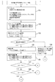
図6,7は、エンジンECU13における補機動力推定制御処理の流れを示すフローチャートである。
【0062】
ステップ101では、冷凍サイクル高圧系圧力値、第1補機動力推定部16によるコンプレッサ14aのトルク推定値Tcomp1、第2補機動力推定部17によるコンプレッサ14aのトルク推定値Tcomp2、および推定条件満足判定等のデータを入力する。
【0063】
ステップ102では、トルクのマージン量Ts1,Ts2を計算する。このマージン量Ts1,Ts2とは、推定したトルクの誤差を見込んで、あらかじめ大きめに推定し、万一、実際のトルクよりも過小に見積もった場合でも、ここで算出したマージン量Ts1,Ts2を加算し、実際のトルクよりも小さくならないようにするためである。もし実際のトルクよりも小さい推定を行うと、例えば、車両がアイドル状態などでエンジンの回転数が非常に低い条件では、エンジン10の駆動力が小さく、補機14の動力分を過小に見積もると、エンジン10が停止する、つまりエンスト現象が発生することが考えられる。この現象を避けるため、このマージン量Ts1,Ts2を設定する。具体的な計算方法としては、冷凍サイクル高圧系の圧力値などを用いる。ここで、マージン量Ts1,Ts2としては、第1補機動力推定部16によるトルク推定値に加えるマージン量Ts1を、第2補機動力推定部17によるトルク推定値に加えるマージン量Ts2よりも大きく設定する。
【0064】
ステップ103では、このマージン量Ts1,Ts2を加えてトルク推定値Tcomp1,Tcomp2をそれぞれ修正する。この操作により、計算したトルク推定値Tcomp1,Tcomp2の誤差を含めたトルクの上限値を見積もることができる。
【0065】
ステップ104では、第2補機動力推定部17による動力推定時に、指定された条件を満足したかどうかを判定する。条件を満足していない場合には、ステップ109へ進み、第1補機動力推定部16によるトルク推定値Tcomp1を採用して本制御を終了する。一方、上記条件を満足している場合には、ステップ105へ進む。
【0066】
ステップ105では、2つのトルク推定値Tcomp1,Tcomp2による偏差ΔTを計算する。
【0067】
ステップ106では、偏差ΔTが適正かどうかを判定するために、偏差判定値Th1,Th2を計算する。一般に偏差判定値を固定することも可能であるが、種々の条件でより正確に判定するために、個々の条件に合わせた判定値を算出し、これを利用する。
【0068】
ステップ107では、偏差ΔTを第1の偏差判定値Th1と比較する。偏差ΔTが第1の偏差判定値Th1以下の場合には、第2補機動力推定部17によるトルク推定値は適正であると判定し、ステップ118へ進む。一方、偏差ΔTが第1の偏差判定値Th1よりも大きい場合には、ステップ108へ進む。
【0069】
ステップ108では、偏差ΔTを第1の偏差判定値Th1よりも大きな第2の偏差判定値Th2と比較する。偏差ΔTが第2の偏差判定値Th2以下の場合には、本制御を終了する。一方、偏差ΔTが第2の偏差判定値Th1よりも大きい場合には、ステップ110へ進む。
【0070】
ステップ110では、偏差ΔTが非常に大きいため、第2補機動力推定部17は破損していると判定する。
【0071】
ステップ111では、この破損について乗員へ表示告知し、エンジンECU13による第1補機動力推定部16によるトルク推定値を採用する。
【0072】
ステップ112では、第2補機動力推定部17は経年変化により推定動力の修正が必要と判定する。
【0073】
ステップ113では、補機動力の修正のため、補機使用条件をデータとして、車両の速度、冷凍サイクルの高圧系圧力値、外気温度等のデータなどを入力する。
【0074】
ステップ114では、補機使用条件が安定しているかどうかを判定し、安定していると判定された場合には、ステップ115へ進み、安定していないと判断された場合には、ステップ116へ進む。
【0075】
ステップ115では、推定動力の修正量Tcを計算する。
【0076】
ステップ116では、前回の修正量Tcをそのまま用いる。
【0077】
ステップ117では、ステップ115またはステップ116により求められた修正量TcをトルクTcomp2に加えて推定動力を修正する。
【0078】
ステップ118では、トルクTcomp2をトルクTcompとして本制御を終了する。
【0079】
次に、効果を説明する。
第1実施例の車両用制御装置にあっては、以下に列挙する効果を得ることができる。
【0080】
(1) 第1補機動力推定部16と第2補機動力推定部17とで算出したコンプレッサ14aのトルク推定値Tcomp1,Tcomp2から偏差ΔTを算出し、この偏差ΔTが偏差判定値Th1以下である場合に、第2補機動力推定部17により推定されたトルク推定値Tcomp2に基づいてエンジン制御を行うこととしたため、より正確なコンプレッサ14aのトルク推定ができ、エンジン10の燃料消費量を改善することができる。
【0081】
(2) トルク推定値Tcomp1,Tcomp2にマージン量Ts1,Ts2を加算し、算出したトルク推定値Tcomp1,Tcomp2の誤差を含めたトルクの上限値を見積もることとしたため、より高精度なトルク推定を行うことができる。
【0082】
(3) 第2補機動力推定部17によりトルク推定値Tcomp2を求めるとき、指定された条件を満足したかどうかを判定し、条件を満足しない場合には第1補機動力推定部16により求めたトルク推定値Tcomp1を用いてエンジン制御を行うこととしたため、補機ECU15の処理ルーチンよりも短い時間に動力推定が必要なとき、または第2補機動力推定部17が故障しているときでも、燃料消費量の改善を図ることができる。
【0083】
(4) 偏差ΔTがマージン量Ts1よりも大きく、かつ、マージン量Ts2以下である場合には、トルク推定値Tcomp2に修正量Tcを加えて修正を行うこととしたため、第2補機動力推定部17によるトルク推定精度を向上させることができる。
【0084】
(5) 偏差ΔTがマージン量Ts2(>Ts1)よりも大きい場合には、第2補機動力推定部17は破損していると判断し、第1補機動力推定部16により算出されたトルク推定値Tcomp1を用いて制御を行うこととしたため、補機ECU15の破損時においても適正なエンジン制御を行うことができる。
【0085】
(その他の実施例)
以上、本発明の車両用制御装置を第1実施例に基づき説明してきたが、具体的な構成については、この第1実施例に限られるものではなく、特許請求の範囲の各請求項に係る発明の要旨を逸脱しない限り、設計の変更や追加等は許容される。
【0086】
例えば、第1実施例では、補機14の動力推定として外部制御可変容量コンプレッサ14aのトルク推定のみを例に示したが、補機14としては、外部制御オルタネータ、外部制御エンジン冷却ファン、外部制御エンジン冷却水ポンプ等を用いても良く、これらを組み合わせた構成としても良い。
【図面の簡単な説明】
【図1】実施の形態1の車両用制御装置を示すブロック図である。
【図2】実施の形態2の車両用制御装置を示すブロック図である。
【図3】第1実施例の車両用制御装置を示す全体システム図である。
【図4】外部制御可変容量コンプレッサを示す断面図である。
【図5】コンプレッサのコントロールバルブに対するデューティ信号によるコンプレッサ吐出容量(吐出側圧力)の制御作用説明図である。
【図6】エンジンECUにおける補機動力推定制御処理の流れを示すフローチャートである。
【図7】エンジンECUにおける補機動力推定制御処理の流れを示すフローチャートである。
【符号の説明】
1 エンジン
2 エンジン用センサ
3 エンジンECU
4 補機
5 補機ECU
6 第1補機動力推定部
7 第2補機動力推定部
8 推定動力偏差監視手段
11 エンジン
12 エンジン用センサ
13 エンジンECU
14 補機
14a 外部制御可変容量コンプレッサ
15 補機ECU
16 第1補機動力推定部
17 第2補機動力推定部
18 推定動力偏差監視手段[0001]
BACKGROUND OF THE INVENTION
The present invention belongs to the technical field of a vehicle control device that controls a vehicle based on auxiliary machine power.
[0002]
[Prior art]
As this type of vehicle control device, for example, a technique described in JP-A-1-175517 is known. This conventional publication discloses a technique for obtaining a suction pressure set value from a detected heat load, calculating a required torque for driving a variable displacement compressor, and using it for engine control.
[0003]
That is, in this prior art, the torque that is the power of the auxiliary machine is calculated using the thermal load calculating means, the required driving torque calculating means, and the idle-up control means, and is used for engine idle control.
[0004]
[Problems to be solved by the invention]
By the way, in the above prior art, it is presumed that the required driving torque calculation means of the compressor performs calculation processing by an electronic device. As a specific electronic device, an air conditioning control ECU or an engine control is used. It will be an ECU. Further, although the specific electronic device is not clearly shown in the idle-up control means, it is considered that it is probably an engine control ECU.
[0005]
That is, if the torque calculation means is an air-conditioning control ECU, communication with the engine control ECU is required. If the torque calculation means is an engine control ECU, signals are exchanged in the engine control ECU. It is thought that engine control called control is performed.
[0006]
Here, if the torque calculating means is in the engine control ECU, a processing routine for calculating the required driving torque is required as processing in the engine control ECU. In general, since engine control is very fast, in order to perform a processing routine with a long processing time in the engine control, a CPU (Central Processing Processor) capable of processing at a higher speed is required as the engine control ECU. There was a problem that the control ECU was expensive.
[0007]
On the other hand, if the torque calculating means is in the air conditioning control ECU, the reliability of the air conditioning control ECU is lower than that of the engine control ECU from the viewpoint of manufacturing cost reduction. For this reason, when the air-conditioning control ECU is damaged or malfunctions, incorrect torque data is communicated to the engine control ECU. In other words, if the torque data is larger than the true value, the fuel consumption of the engine is deteriorated. Conversely, if the torque data is smaller than the true value, a phenomenon called engine stall (so-called engine stall) occurs, and the vehicle travels. There was a problem that the danger increased.
[0008]
The present invention has been made paying attention to the above-mentioned problem, and an object of the present invention is to provide a vehicular control apparatus that can more accurately estimate the auxiliary machine power without increasing the processing load of the engine control means. Is to provide.
[0009]
[Means for Solving the Problems]
In order to achieve the above object, in the vehicle control apparatus according to claim 1 of the present invention, an engine which is a main drive source of the vehicle, an engine control means for controlling the engine, and the engine directly or directly. In a vehicle control device comprising an indirectly driven auxiliary machine and an auxiliary machine control means for controlling the auxiliary machine, a first auxiliary machine is provided in the engine control means as means for estimating a physical quantity related to the power of the auxiliary machine. An auxiliary machine power estimation unit is provided, and an auxiliary machine control unit is provided with a second auxiliary machine power estimation unit. The accuracy of auxiliary machine power estimated by the second auxiliary machine power estimation unit is determined by the first auxiliary machine power estimation unit. It is characterized by being set higher than the force estimation accuracy.
[0010]
According to a second aspect of the present invention, in the vehicle control device according to the first aspect, the engine control means transmits an estimation condition to the auxiliary machine control means, and the auxiliary machine control means satisfies the estimated condition. Based on this, the second auxiliary power estimation unit estimates the auxiliary power and transmits the estimated value to the engine control means.
[0011]
According to a third aspect of the present invention, in the vehicle control device according to the second aspect, the estimation condition is at least one of a response grace time for auxiliary power estimation, a time timing to be predicted, or a prediction accuracy. It is characterized by being.
[0012]
According to a fourth aspect of the present invention, in the vehicular control apparatus according to the third aspect, the engine control means is configured such that when the second auxiliary power estimation unit does not satisfy at least one of the estimation conditions, Auxiliary machine power is estimated by a force estimation unit.
[0013]
According to a fifth aspect of the present invention, in the vehicle control device according to any one of the first to fourth aspects, the first auxiliary power estimation unit and the second auxiliary power estimation unit respectively estimate the vehicle control device. An estimated power deviation monitoring means for calculating whether or not the deviation is equal to or greater than a predetermined value, and the engine control means includes a first auxiliary machine operation when the deviation exceeds a predetermined value. Auxiliary machine power is estimated by a force estimation unit.
[0014]
According to a sixth aspect of the present invention, in the vehicle control device according to the fifth aspect, the engine control means is configured such that when the deviation continues for a predetermined time, a predetermined frequency, or a predetermined number of times, the second auxiliary power estimation unit It is characterized in that it is determined that is damaged.
[0015]
According to a seventh aspect of the present invention, in the vehicle control device according to the fifth or sixth aspect, the engine control means has a deviation larger than a first predetermined value and larger than a first predetermined value. 2 When smaller than a predetermined value, the auxiliary power estimated by the second auxiliary power estimation unit is corrected.
[0016]
According to an eighth aspect of the present invention, in the vehicle control device according to any one of the fifth to seventh aspects, the deviation is compared under a predetermined condition.
[0017]
According to a ninth aspect of the present invention, in the vehicle control device according to any one of the first to eighth aspects, the estimated power is at least one of engine control, transmission control, and accessory control. It is used for one.
[0018]
According to a tenth aspect of the present invention, in the vehicle control device according to any one of the first to ninth aspects, the auxiliary device is an air conditioner capable of setting a refrigerant discharge amount per rotation by an external signal. Compressor, air conditioning compressor whose speed can be set by external signal, power generator alternator that can set power generation amount by external signal, engine cooling fan whose speed can be set by external signal, air volume can be set by external signal Engine cooling fan, cooling water pump whose speed can be set by external signal, cooling water pump whose water flow rate can be set by external signal, auxiliary water pump for heaters whose speed can be set by external signal, or water by external signal It is at least one of the auxiliary water pumps for heaters which can set a flow volume.
[0019]
Operation and effect of the invention
In the first aspect of the invention, as the auxiliary power estimation means, the engine control means is provided with the first auxiliary power estimation section, the auxiliary control means is provided with the second auxiliary power estimation section, and at least two auxiliary power is provided. The auxiliary power estimation means is used. Therefore, it is possible to estimate the auxiliary power more accurately than in the prior art, and the fuel consumption can be improved by applying to the control of the engine or the like.
[0020]
Moreover, since the estimation accuracy of the auxiliary machine power by the second auxiliary machine power estimation unit is set higher than the estimation accuracy of the auxiliary machine power by the first auxiliary machine power estimation unit, the calculation load of the engine control means can be kept low. Therefore, compared with the conventional apparatus in which the auxiliary machine power estimation means is provided only in the engine control means, the cost of the calculation means such as a microcomputer used as the engine control means can be reduced.
[0021]
On the other hand, by using two auxiliary power estimation means, it is possible to avoid deterioration of fuel consumption, engine stall, etc. due to failure or malfunction of the auxiliary power estimation means. Compared with the conventional apparatus provided only in the above, the reliability of control can be further improved.
[0022]
According to the second aspect of the present invention, the auxiliary power estimation condition is presented from the engine control means to the auxiliary control means, so that more accurate auxiliary power can be estimated under necessary conditions. Therefore, when the estimated auxiliary machine power is used for control of the engine or the like, the fuel consumption or the power performance of the vehicle can be improved.
[0023]
According to the third aspect of the present invention, when the response grace time, the timing to be predicted, the prediction accuracy, or the like is used as a condition, for example, when the condition is the timing to be predicted, the auxiliary machine motion estimated by the engine control means By clearly indicating the point in time when the force is required, the engine and the like can be controlled more precisely based on the estimated accessory power.
[0024]
In the invention according to claim 4, when the estimation condition is not satisfied, the auxiliary machine power is estimated by the first auxiliary machine power estimating unit instead of the second auxiliary machine power estimating unit. As a result, when the auxiliary power estimated by the first auxiliary power estimation unit cannot be output for some reason, the accuracy is lower than that estimated by the first auxiliary power estimation unit, but compared with the case where the auxiliary power is not estimated. Thus, the control accuracy can be further increased.
[0025]
In the fifth aspect of the present invention, the auxiliary machine power estimated by the first auxiliary machine power estimating unit is compared with the auxiliary machine power estimated by the second auxiliary machine power estimating unit. And when the difference (deviation) of both auxiliary machine power is large, an auxiliary machine power is estimated by the 1st auxiliary machine power estimation part. Therefore, it is not necessary to use a highly durable component such as the engine control means as the auxiliary machine control means, so that the apparatus can be configured at low cost.
[0026]
In the invention according to
[0027]
In the invention according to
[0028]
That is, when the deviation is within a predetermined range and it is not determined that the sensor is broken, it can be determined that the sensor detection accuracy has deteriorated with time, so the auxiliary power estimated by the second auxiliary power estimation unit can be calculated. It can be used with appropriate modifications. For this reason, it is easy to quantitatively understand the effects of deterioration over time, etc., and the second auxiliary machine operation is calculated and corrected using the above deviation, with the use conditions being relatively stable. Torque estimation accuracy by the force estimation unit can be improved, and when applied to engine control, fuel consumption and the like can be improved.
[0029]
The invention described in claim 9 describes the field of application of the power estimation method described above, and can be used for controlling a vehicle such as an engine or a transmission by auxiliary power. The invention described in claim 10 is described as an auxiliary machine capable of changing the required power by an external signal.
[0030]
That is, an auxiliary machine that can set the load of the auxiliary machine by an external signal is selected, and the engine or transmission is controlled using the power estimated by the auxiliary machine power estimation means. By changing and setting the power of the auxiliary equipment upon request, the characteristics of the engine or transmission can be further improved, and the fuel consumption and the like can be improved.
[0031]
DETAILED DESCRIPTION OF THE INVENTION
Embodiments of the present invention will be described below with reference to the drawings.
[0032]
(Embodiment 1)
The first embodiment corresponds to the inventions according to
FIG. 1 is a block diagram illustrating the vehicle control apparatus according to the first embodiment.
The engine 1 includes several engine sensors 2, and the engine 1 is controlled by an engine ECU (electronic control unit) 3. Further, an auxiliary machine 4 such as an external control displacement variable compressor directly or indirectly driven by the engine 1 is provided, and this auxiliary machine 4 is controlled by an
[0033]
The
[0034]
Since the
[0035]
When the
[0036]
In addition, as a target situation, in order to accurately estimate the auxiliary machine power, at least one of the time delay for the
[0037]
When the second auxiliary machine
[0038]
As a result, the torque estimation accuracy is deteriorated, so that the engine rotation speed is generally increased and the fuel consumption is deteriorated as compared with the case where the engine rotation speed at the time of idling has a high accuracy. However, the accuracy is better than when torque estimation is not performed. That is, when there is sufficient time to reach the idle state at the time of deceleration, the auxiliary power is estimated by the second auxiliary
[0039]
(Embodiment 2)
The second embodiment corresponds to the invention according to claims 1 to 10.
FIG. 2 is a block diagram illustrating the vehicle control apparatus according to the second embodiment. The configuration of the second embodiment is different from the first embodiment in that the estimated power deviation monitoring means 8 is provided in the
[0040]
The
[0041]
That is, compared with the
[0042]
When the deviation continues for a predetermined time, a predetermined frequency, or a predetermined number of times, it may be determined that the
[0043]
Here, when there is a deviation, but larger than the first set value and smaller than the second set value that is larger than the first set value, the
[0044]
Further, if there is a deviation, the deviation amount may be accurately measured, and a condition for measuring the deviation amount may be defined in order to set the correction amount more accurately. For example, the deviation is recorded on the condition that the control of the engine 1 and the transmission (not shown) running on a flat road at a constant speed is relatively stable. Then, this history database is used, or the output data of the second auxiliary machine
[0045]
Next, examples will be described.
(First embodiment)
First, the configuration will be described.
FIG. 3 is an overall system diagram showing the vehicle control apparatus of the first embodiment.
The
[0046]
Next, although there are various
[0047]
The
[0048]
FIG. 4 is a sectional view showing the externally controlled
[0049]
The
[0050]
The
[0051]
As shown in FIG. 4, the lift amount of the high pressure ball valve 36 is determined by the balance between the low pressure pressure (= suction side pressure Ps) applied to the diaphragm of the
[0052]
For example, a 400 Hz pulse signal ON-OFF signal (duty signal) is sent from the
[0053]
Returning to FIG. 3, communication is performed between the
[0054]
Communication is also performed between the
[0055]
Here, in order for the
[0056]
As will be described later, since the estimated power by the second auxiliary
[0057]
The first auxiliary machine
[0058]
On the other hand, the second auxiliary machine
[0059]
The
[0060]
Further, the
[0061]
Next, the operation will be described.
[Auxiliary power estimation control processing]
6 and 7 are flowcharts showing the flow of auxiliary power estimation control processing in the
[0062]
In
[0063]
In
[0064]
In
[0065]
In
[0066]
In
[0067]
In
[0068]
In
[0069]
In
[0070]
In
[0071]
In
[0072]
In
[0073]
In
[0074]
In
[0075]
In
[0076]
In
[0077]
In
[0078]
In
[0079]
Next, the effect will be described.
In the vehicle control apparatus of the first embodiment, the effects listed below can be obtained.
[0080]
(1) The deviation ΔT is calculated from the estimated torque values Tcomp1 and Tcomp2 of the
[0081]
(2) Since the margin amounts Ts1 and Ts2 are added to the estimated torque values Tcomp1 and Tcomp2 and the upper limit value of the torque including the error of the calculated estimated torque values Tcomp1 and Tcomp2 is estimated, more accurate torque estimation is performed. be able to.
[0082]
(3) When the estimated torque value Tcomp2 is obtained by the second auxiliary machine
[0083]
(4) When the deviation ΔT is larger than the margin amount Ts1 and less than or equal to the margin amount Ts2, the correction amount Tc is added to the estimated torque value Tcomp2, and the correction is performed. 17 can improve the torque estimation accuracy.
[0084]
(5) If the deviation ΔT is larger than the margin amount Ts2 (> Ts1), it is determined that the second auxiliary
[0085]
(Other examples)
As mentioned above, although the vehicle control apparatus of the present invention has been described based on the first embodiment, the specific configuration is not limited to the first embodiment, and it relates to each claim of the claims. Design changes and additions are allowed without departing from the scope of the invention.
[0086]
For example, in the first embodiment, only the torque estimation of the external control
[Brief description of the drawings]
FIG. 1 is a block diagram illustrating a vehicle control apparatus according to a first embodiment.
FIG. 2 is a block diagram illustrating a vehicle control apparatus according to a second embodiment.
FIG. 3 is an overall system diagram showing the vehicle control apparatus of the first embodiment.
FIG. 4 is a sectional view showing an externally controlled variable capacity compressor.
FIG. 5 is an explanatory diagram of a control action of a compressor discharge capacity (discharge side pressure) by a duty signal for a control valve of the compressor.
FIG. 6 is a flowchart showing a flow of auxiliary machine power estimation control processing in the engine ECU.
FIG. 7 is a flowchart showing the flow of auxiliary power estimation control processing in the engine ECU.
[Explanation of symbols]
1 engine
2 Sensor for engine
3 Engine ECU
4 Auxiliary machines
5 Auxiliary ECU
6 First Auxiliary Power Estimator
7 Second Auxiliary Power Estimator
8 Estimated power deviation monitoring means
11 Engine
12 Sensor for engine
13 Engine ECU
14 Auxiliary machine
14a External control variable displacement compressor
15 Auxiliary ECU
16 1st auxiliary machine power estimation part
17 Second Auxiliary Power Estimator
18 Estimated power deviation monitoring means
Claims (10)
このエンジンを制御するエンジン制御手段と、
前記エンジンにより直接または間接駆動される補機と、
この補機を制御する補機制御手段と、
を備えた車両用制御装置において、
前記補機の動力に関わる物理量を推定する手段として、エンジン制御手段に第1補機動力推定部を設けるとともに、補機制御手段に第2補機動力推定部を設け、
前記第2補機動力推定部による補機動力の推定精度を、第1補機動力推定部による補機動力の推定精度よりも高く設定したことを特徴とする車両用制御装置。An engine that is the main drive source of the vehicle;
Engine control means for controlling the engine;
An auxiliary machine driven directly or indirectly by the engine;
Auxiliary machine control means for controlling this auxiliary machine,
In a vehicle control device comprising:
As a means for estimating a physical quantity related to the power of the auxiliary machine, a first auxiliary machine power estimation unit is provided in the engine control means, and a second auxiliary machine power estimation unit is provided in the auxiliary machine control means,
The vehicle control apparatus according to claim 1, wherein the estimation accuracy of auxiliary power by the second auxiliary power estimation unit is set higher than the estimation accuracy of auxiliary power by the first auxiliary power estimation unit.
前記エンジン制御手段は、補機制御手段に対して推定条件を送信し、
前記補機制御手段は、推定条件に基づいて第2補機動力推定部により補機動力を推定し、推定値をエンジン制御手段に送信することを特徴とする車両用制御装置。The vehicle control device according to claim 1,
The engine control means transmits an estimation condition to the auxiliary machine control means,
The auxiliary machine control means estimates the auxiliary machine power by the second auxiliary machine power estimation section based on the estimation condition, and transmits the estimated value to the engine control means.
前記推定条件は、補機動力推定の回答猶予時間、予測すべき時間タイミング、または予測精度のうちの少なくとも1つであることを特徴とする車両用制御装置。The vehicle control device according to claim 2,
The vehicle control apparatus according to claim 1, wherein the estimation condition is at least one of a response grace time for auxiliary power estimation, a time timing to be predicted, or a prediction accuracy.
前記エンジン制御手段は、第2補機動力推定部が推定条件の少なくとも1つを満足しないとき、第1補機動力推定部により補機動力を推定することを特徴とする車両用制御装置。The vehicle control device according to claim 3,
The engine control means estimates the auxiliary power by the first auxiliary power estimation unit when the second auxiliary power estimation unit does not satisfy at least one of the estimation conditions.
前記第1補機動力推定部と第2補機動力推定部とによりそれぞれ推定された補機動力の偏差を算出し、その偏差が所定値以上かどうかを監視する推定動力偏差監視手段を備え、
前記エンジン制御手段は、偏差が所定値以上となったとき、第1補機動力推定部により補機動力を推定することを特徴とする車両用制御装置。In the vehicle control device according to any one of claims 1 to 4,
An estimated power deviation monitoring means for calculating a deviation of the auxiliary power estimated by each of the first auxiliary power estimation unit and the second auxiliary power estimation unit and monitoring whether the deviation is a predetermined value or more;
The engine control means estimates the auxiliary machine power by the first auxiliary machine power estimating unit when the deviation becomes a predetermined value or more.
前記エンジン制御手段は、偏差が所定時間、所定頻度、または所定回数以上継続するとき、第2補機動力推定部が破損していると判断することを特徴とする車両用制御装置。The vehicle control device according to claim 5,
The engine control means determines that the second auxiliary power estimation unit is damaged when the deviation continues for a predetermined time, a predetermined frequency, or a predetermined number of times.
前記エンジン制御手段は、偏差が第1所定値より大きく、かつ、第1所定値よりも大きな第2所定値よりも小さいとき、第2補機動力推定部により推定された補機動力を修正することを特徴とする車両用制御装置。In the vehicle control device according to claim 5 or 6,
The engine control means corrects the auxiliary power estimated by the second auxiliary power estimation unit when the deviation is larger than the first predetermined value and smaller than the second predetermined value larger than the first predetermined value. A control apparatus for a vehicle.
前記偏差を所定条件下で比較することを特徴とする車両用制御装置。The vehicle control device according to any one of claims 5 to 7,
A control apparatus for a vehicle, wherein the deviation is compared under a predetermined condition.
前記推定動力を、エンジン制御、変速機制御、または補機制御のうちの少なくとも1つに使用することを特徴とする車両用制御装置。The vehicle control device according to any one of claims 1 to 8,
The vehicle control apparatus characterized in that the estimated power is used for at least one of engine control, transmission control, and accessory control.
前記補機は、外部信号により1回転あたりの冷媒吐出量を設定可能な空調用コンプレッサ、外部信号により回転数を設定可能な空調用コンプレッサ、外部信号により発電量を設定可能な発電用オルタネータ、外部信号により回転数を設定可能なエンジン冷却ファン、外部信号により風量を設定可能なエンジン冷却ファン、外部信号により回転数を設定可能な冷却水ポンプ、外部信号により水流量を設定可能な冷却水ポンプ、外部信号により回転数を設定可能なヒータ用補助水ポンプ、または外部信号により水流量を設定可能なヒータ用補助水ポンプのうちの少なくとも1つであることを特徴とする車両用制御装置。The vehicle control device according to any one of claims 1 to 9,
The auxiliary machine includes an air conditioning compressor capable of setting a refrigerant discharge amount per rotation by an external signal, an air conditioning compressor capable of setting a rotation speed by an external signal, a power generation alternator capable of setting a power generation amount by an external signal, an external Engine cooling fan whose speed can be set by signal, engine cooling fan whose air volume can be set by external signal, cooling water pump whose speed can be set by external signal, cooling water pump whose water flow rate can be set by external signal, A vehicular control device comprising at least one of a heater auxiliary water pump capable of setting a rotation speed by an external signal and a heater auxiliary water pump capable of setting a water flow rate by an external signal.
Priority Applications (3)
| Application Number | Priority Date | Filing Date | Title |
|---|---|---|---|
| JP2002195644A JP4011994B2 (en) | 2002-07-04 | 2002-07-04 | Vehicle control device |
| US10/611,887 US6895754B2 (en) | 2002-07-04 | 2003-07-03 | Vehicle control system |
| EP03291645A EP1378646A3 (en) | 2002-07-04 | 2003-07-03 | Vehicle control system |
Applications Claiming Priority (1)
| Application Number | Priority Date | Filing Date | Title |
|---|---|---|---|
| JP2002195644A JP4011994B2 (en) | 2002-07-04 | 2002-07-04 | Vehicle control device |
Publications (2)
| Publication Number | Publication Date |
|---|---|
| JP2004036521A JP2004036521A (en) | 2004-02-05 |
| JP4011994B2 true JP4011994B2 (en) | 2007-11-21 |
Family
ID=29720293
Family Applications (1)
| Application Number | Title | Priority Date | Filing Date |
|---|---|---|---|
| JP2002195644A Expired - Fee Related JP4011994B2 (en) | 2002-07-04 | 2002-07-04 | Vehicle control device |
Country Status (3)
| Country | Link |
|---|---|
| US (1) | US6895754B2 (en) |
| EP (1) | EP1378646A3 (en) |
| JP (1) | JP4011994B2 (en) |
Families Citing this family (5)
| Publication number | Priority date | Publication date | Assignee | Title |
|---|---|---|---|---|
| JP4702092B2 (en) * | 2006-02-22 | 2011-06-15 | トヨタ自動車株式会社 | Vehicle control apparatus and cooling fan power consumption estimation method |
| US7987035B2 (en) * | 2006-06-27 | 2011-07-26 | Sauer-Danfoss Inc. | Method of operating a vehicle and apparatus comprising the same |
| US7634350B2 (en) * | 2006-11-30 | 2009-12-15 | Caterpillar Inc. | Automatic configuration for a secondary engine electronic governor |
| KR101403721B1 (en) | 2007-12-27 | 2014-06-03 | 한라비스테온공조 주식회사 | Calculating method of expected torque for air conditioner of vehicle |
| PT2965759T (en) | 2012-02-06 | 2020-02-07 | Innovative Med Concepts Llc | Antiviral compound and cox-2 inhibitor combination therapy for functional somatic syndromes |
Family Cites Families (8)
| Publication number | Priority date | Publication date | Assignee | Title |
|---|---|---|---|---|
| CA2184593C (en) * | 1994-03-01 | 2004-11-09 | Guy E. Willis | Small compact auxiliary power system for heavy duty diesel engine installations |
| GB2329713A (en) * | 1997-09-30 | 1999-03-31 | Ford Global Tech Inc | IC engine net torque calculator |
| JP3003675B2 (en) * | 1998-07-07 | 2000-01-31 | 株式会社デンソー | Control device for hybrid electric vehicle |
| US6209672B1 (en) * | 1998-09-14 | 2001-04-03 | Paice Corporation | Hybrid vehicle |
| JP3383231B2 (en) * | 1998-12-17 | 2003-03-04 | 本田技研工業株式会社 | Control device for hybrid vehicle |
| DE19919682A1 (en) | 1999-04-30 | 2000-11-02 | Bosch Gmbh Robert | Controlling drive unit of motor vehicle e.g. power steering by determining demand based on steering angle and time gradient parameters |
| US6279531B1 (en) | 1999-08-09 | 2001-08-28 | Ford Global Technologies, Inc. | System and method for controlling engine torque |
| US6379283B1 (en) | 2000-04-18 | 2002-04-30 | Ford Global Technologies, Inc. | Torque estimation method for an internal combustion engine |
-
2002
- 2002-07-04 JP JP2002195644A patent/JP4011994B2/en not_active Expired - Fee Related
-
2003
- 2003-07-03 EP EP03291645A patent/EP1378646A3/en not_active Withdrawn
- 2003-07-03 US US10/611,887 patent/US6895754B2/en not_active Expired - Fee Related
Also Published As
| Publication number | Publication date |
|---|---|
| EP1378646A3 (en) | 2007-09-26 |
| EP1378646A2 (en) | 2004-01-07 |
| US20040093870A1 (en) | 2004-05-20 |
| JP2004036521A (en) | 2004-02-05 |
| US6895754B2 (en) | 2005-05-24 |
Similar Documents
| Publication | Publication Date | Title |
|---|---|---|
| JP4580816B2 (en) | Torque calculation device and torque calculation method for variable displacement compressor | |
| JP4866568B2 (en) | Torque calculation device for variable displacement compressor | |
| US6487869B1 (en) | Compressor capacity control system | |
| US7921705B2 (en) | Engine coolant temperature estimation system | |
| JP4682904B2 (en) | Compressor drive torque estimation device and compressor drive source control device. | |
| US5724941A (en) | Malfunction diagnosis device of an internal combustion engine controller | |
| JP2004076689A (en) | Abnormality diagnostic device for cooling system of internal combustion engine | |
| US7841197B2 (en) | Torque calculation apparatus and torque calculation method of variable capacitance compressor | |
| US7299993B2 (en) | Apparatus for detecting a failure of a thermostat for an engine | |
| JP4011994B2 (en) | Vehicle control device | |
| CN104514705B (en) | The control of pumping system | |
| JP4119143B2 (en) | Driving torque calculation device for variable displacement compressor | |
| US20040020452A1 (en) | Method and apparatus for controlling CVVT of an engine | |
| JP3921430B2 (en) | Compressor torque estimation device | |
| US6192700B1 (en) | Air conditioning system for a motor vehicle | |
| KR101491143B1 (en) | Control method of a compressor of air conditioner for vehicle | |
| JP5263084B2 (en) | Outside air temperature estimation device | |
| JP2004115012A (en) | Air conditioner provided with controller | |
| JP6531716B2 (en) | Torque estimation device for vehicle air conditioner | |
| KR101427423B1 (en) | Calculating method of expected torque for air conditioner of vehicle | |
| KR20090071192A (en) | Calculating method of expected torque for air conditioner of vehicle | |
| KR101403851B1 (en) | Calculating method of expected torque for air conditioner of vehicle | |
| JP2009510309A (en) | Method to detect deviation between actual torque and calculated torque | |
| CN106194394B (en) | Method for determining the internal temperature of an engine | |
| US10538146B2 (en) | Reducing externally variable displacement compressor (EVDC) start-up delay |
Legal Events
| Date | Code | Title | Description |
|---|---|---|---|
| A621 | Written request for application examination |
Free format text: JAPANESE INTERMEDIATE CODE: A621 Effective date: 20041202 |
|
| RD04 | Notification of resignation of power of attorney |
Free format text: JAPANESE INTERMEDIATE CODE: A7424 Effective date: 20051114 |
|
| TRDD | Decision of grant or rejection written | ||
| A977 | Report on retrieval |
Free format text: JAPANESE INTERMEDIATE CODE: A971007 Effective date: 20070830 |
|
| A01 | Written decision to grant a patent or to grant a registration (utility model) |
Free format text: JAPANESE INTERMEDIATE CODE: A01 Effective date: 20070904 |
|
| A61 | First payment of annual fees (during grant procedure) |
Free format text: JAPANESE INTERMEDIATE CODE: A61 Effective date: 20070906 |
|
| R150 | Certificate of patent or registration of utility model |
Free format text: JAPANESE INTERMEDIATE CODE: R150 |
|
| FPAY | Renewal fee payment (event date is renewal date of database) |
Free format text: PAYMENT UNTIL: 20100914 Year of fee payment: 3 |
|
| S531 | Written request for registration of change of domicile |
Free format text: JAPANESE INTERMEDIATE CODE: R313531 |
|
| FPAY | Renewal fee payment (event date is renewal date of database) |
Free format text: PAYMENT UNTIL: 20100914 Year of fee payment: 3 |
|
| R350 | Written notification of registration of transfer |
Free format text: JAPANESE INTERMEDIATE CODE: R350 |
|
| LAPS | Cancellation because of no payment of annual fees |