JP4010809B2 - Ultrasonic diagnostic equipment - Google Patents
Ultrasonic diagnostic equipment Download PDFInfo
- Publication number
- JP4010809B2 JP4010809B2 JP2001396476A JP2001396476A JP4010809B2 JP 4010809 B2 JP4010809 B2 JP 4010809B2 JP 2001396476 A JP2001396476 A JP 2001396476A JP 2001396476 A JP2001396476 A JP 2001396476A JP 4010809 B2 JP4010809 B2 JP 4010809B2
- Authority
- JP
- Japan
- Prior art keywords
- image
- pulse
- flash
- monitor
- ultrasonic
- Prior art date
- Legal status (The legal status is an assumption and is not a legal conclusion. Google has not performed a legal analysis and makes no representation as to the accuracy of the status listed.)
- Expired - Fee Related
Links
Images


Description
【0001】
【発明の属する技術分野】
本発明は、超音波診断装置に係わり、特に超音波造影剤を用いて患者の内臓などの検査を行う、いわゆるコントラストエコー法による超音波診断装置に関する。
【0002】
【従来の技術】
患者の内臓を検査する場合、超音波のパルスを体内に発射し、体内から反射されてきた反射パルスを用いて軟部組織の断層像を得る、超音波診断装置が知られている。この種の超音波診断装置の1つに、超音波造影剤を患者の体内に注入し血流動態を調べて心臓や腹部臓器などの検査を行うコントラストエコー法による超音波診装置がある。
【0003】
上記コントラストエコー法に用いる超音波造影剤は、近年、基材の改良によってその成分である気泡の微小化が可能となり、静脈投与によっても肺を経て左心室に到達可能となって有用性が増している。静脈からの造影剤注入は侵襲性が小さく、この点からも有利で、このような血流動態の評価法による診断が普及しつつある。
【0004】
ところで、コントラストエコー法では、通常、撮像し検査のための鮮明な画像(フラッシュ画像)を得るためのモード(撮影モード)の他に、超音波プローブを手で操作するので、常時、超音波の放射方向や位置を確認する必要があり、そのための動画像(モニタ画像)を得るためのモード(モニタモード)がある。
【0005】
一方、上記超音波造影剤により血流中に生じる気泡は、比較的強い超音波を受けると消失してしまい、再び気泡が存在するようになるまでに時間がかかる。フラッシュ画像を得る為に強い超音波、すなわち高い音圧の超音波ビームを照射することは、鮮明な画像を得るためには必要不可欠であるが、モニタ画像を得るためには患者のどの部位に超音波が当たっているかを知ればいいので、血流中に生じている気泡を壊さないために、通常、比較的弱い超音波、すなわち低い音圧の超音波ビームが用いられる。したがって、気泡を壊さない程度の超音波パルスを複数回照射した後、1回又は複数回強い超音波パルスを照射することにより、超音波の照射部位を確認しながら鮮明なフラッシュ画像を得ることが多い。これらのモニタ画像とフラッシュ画像は、通常、同じ表示装置の画面で重畳表示される。
【0006】
このようにモニタ画像とフラッシュ画像を得る場合、音圧の高い超音波ビームと音圧の低い超音波ビームの2種類を発生させる必要があるが、これらのビームを発生させる高電圧電源には、出力電圧が比較的高いものと比較的低いものの2つの電源を用意し切り替える方法と、1電源を用いて出力が低い電圧になる場合と高い電圧になる場合のように出力電圧を制御する方法がある。
【0007】
特に、後者の方法による超音波診断装置では、周期的な低い電圧パルスから安定した周期的な高い電圧パルスに、また高い電圧パルスから低い電圧パルスに出力を変えなければならず、その移行のための時間が必要であった。また、前者の方法による超音波診断装置においても、電圧源を切り替える時間があり、他にも画質パラメータやフォーカス処理のための時間などが必要となる。この時間をここでは、モード切り替え時間ということにする。
【0008】
一方、フラッシュ画像を得るため、高音圧の超音波ビームを照射した後、次の高音圧超音波ビームを照射するまでの時間(フラッシュインターバルタイム、以下略してインターバルタイムともいう)は、血流中に気泡が充分存在し、再び気泡が充分に存在するまでの時間以上であれば、撮影に問題はなく、この時間を短くすれば所定時間内に多くのフラッシュ画像が得られるので、しばしばこのインターバルタイムを短く変化させることがある。
【0009】
インターバルタイムが長いときには、高音圧の超音波ビームを照射し上記モード移行時間を経た後、残った時間内で低音圧の超音波ビームを照射して、モニタ画像を得ている。ところが、低音圧の超音波ビームを照射してからモニタ画像を得るまでの時間(モニタ画像取得時間)を一定とすると、上述のようにインターバルタイムが短くなってくると、モード切り替え時間が確保できなくなる。
【0010】
そのため、従来のこの種の超音波診断装置では、インターバルタイムが(モード移行時間+モニタ画像取得時間)よりも短くならないように制限していた。しかしこのようにインターバルタイムに下限の制限があると、所定時間内に多くのフラッシュ画像を得ることができないという問題点があった。
【0011】
【発明が解決しようとする課題】
上述のように、従来のコントラストエコー法による超音波診断装置においては、インターバルタイムの変化範囲の下限が制限され、所定時間内に多くのフラッシュ画像を取得できないという問題点があった。
【0012】
本発明は、このような従来の超音波装置の問題点に鑑みてなされたもので、インターバルタイムの下限を短くすることができ、したがって所定時間内に多くのフラッシュ画像を得ることが可能な、コントラストエコー法による超音波診断装置を提供することを目的とする。
【0013】
【課題を解決するための手段】
上記目的を達成するために、本発明の請求項1によれば、超音波造影剤を注入された患者の体内に超音波を照射し、撮影のためのフラッシュ画像と撮影の部位を確認するためのモニタ画像を取得して表示するパルスエコー法を用いた超音波診断装置であって、前記フラッシュ画像を得るために照射する超音波パルスの時間間隔であるフラッシュインターバルタイムと前記フラッシュ画像を得るモードから前記モニタ画像を得るモードに移行するモード切り替え時間との比較に基づいて、前記モニタ画像を得るためのモニタパルスを停止することを特徴とする超音波診断装置を提供する。
【0014】
本発明の請求項2によれば、超音波造影剤を注入された患者の体内に超音波パルスを照射し、この照射された超音波パルスの反射波を受ける超音波プローブと、
この超音波プローブに比較的高い電圧のフラッシュパルス及びこの電圧よりも低い電圧のモニタパルスを供給する高電圧電源と、前記超音波プローブにより受けた反射波のうち、前記フラッシュパルスに対応する反射波から撮影のためのフラッシュ画像の電気信号を取得し、前記モニタパルスに対応する反射波から撮影の部位を確認するためのモニタ画像の電気信号を取得する処理手段と、この処理手段により取得された電気信号から前記フラッシュ画像及び前記モニタ画像を表示する表示手段と、前記フラッシュ画像を得るために照射する超音波パルスの時間間隔であるフラッシュインターバルタイムを、前記フラッシュ画像を得るモードから前記モニタ画像を得るモードに移行するモード切り替え時間と比較する比較手段と、前記フラッシュインターバルタイムが前記モード切り替え時間より短いとき、前記モニタパルスを停止するモニタ画像表示制御手段とを有することを特徴とする、パルスエコー法を用いた超音波診断装置を提供する。
【0015】
本発明の請求項3によれば、超音波造影剤を注入された患者の体内に超音波を照射し、撮影のためのフラッシュ画像と撮影の部位を確認するためのモニタ画像を取得して表示するパルスエコー法を用いた超音波診断装置であって、前記フラッシュ画像を得るために照射する超音波パルスの時間間隔であるインターバルタイムを、前記フラッシュ画像を得るモードから前記モニタ画像を得るモードに移行するモード切り替え時間より短くしたことにより前記モニタ画像の電気信号が取得できなかったとき、前記モニタ画像を得るためのモニタパルスを停止することを特徴とする超音波診断装置を提供する。
【0016】
本発明の請求項4によれば、超音波造影剤を注入された患者の体内に超音波パルスを照射し、この照射された超音波パルスの反射波を受ける超音波プローブと、この超音波プローブに比較的高い電圧のフラッシュパルス及びこの電圧よりも低い電圧のモニタパルスを供給する高電圧電源と、前記超音波プローブにより受けた反射波のうち、前記フラッシュパルスに対応する反射波から撮影のためのフラッシュ画像の電気信号を取得し、前記モニタパルスに対応する反射波から撮影の部位を確認するためのモニタ画像の電気信号を取得する処理手段と、この処理手段により取得された電気信号から前記フラッシュ画像及び前記モニタ画像表示する表示手段と、前記フラッシュ画像を得るために照射する超音波パルスの時間間隔であるフラッシュインターバルタイムを、前記フラッシュ画像を得るモードから前記モニタ画像を得るモードに移行するモード切り替え時間より短くしたことにより前記モニタ画像の電気信号を取得できなかった場合に前記モニタパルスを停止するモニタ画像表示制御手段とを有することを特徴とする、パルスエコー法を用いた超音波診断装置を提供する。
【0017】
【発明の実施の形態】
以下、本発明の各実施形態について図面を用いて説明する。
【0018】
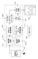
図1に、本発明の一実施形態の超音波診断装置の構成例を示す。この超音波診断装置100は、装置本体101と、超音波を図示しない患者に照射し反射されてきた超音波を受ける超音波プローブ102と、装置本体101で処理された画像を表示するモニタ装置103と、フラッシュインターバルタイムを制御するための入力を行う操作パネル14とから成る。
【0019】
装置本体101は、超音波プローブ102から超音波ビームを送信するための電気信号(駆動パルス)を発生する高電圧電源105と、この高電圧電源105の発生した電気信号を処理して上記超音波プローブ12に駆動パルスを印加すると共に、これにより受けた超音波反射波の信号を処理する送受信回路106と、この送受信回路106により処理された反射信号をBモード画像を表示できるように処理するBモード処理回路107と、この回路の出力を処理するデジタルスキャンコンバータ(DSC)108と、このDSC108の出力を供給されるシネメモリ109と、このシネメモリ109出力のフラッシュ画像信号及び上記DSC108出力のモニタ画像信号を合成し上記モニタ装置103に合成信号を供給する合成回路110と、上記操作パネル104から入力される信号に応じてフラッシュインターバルタイムを制御するインターバルタイム制御回路111とから成る。
【0020】
次に、図面を用いてこの実施形態の動作を説明する。装置本体101の高電圧電源105からは、図2(a)に示すように、比較的高い電圧のパルスFPと比較的低い電圧の複数、例えば3つのパルスMP1,MP2,MP3のパルス列が繰り返し出力され、送受信回路106を介して超音波プローブ102に送られる。なお、同図において、フラッシュパルスFPから次のフラッシュパルスFPまでの時間が、インターバルタイムITである。
【0021】
一方、患者の静脈には予め、超音波造影剤が注入されており、血流中に微小気泡が生じている。したがって上記の電圧パルスが超音波プローブ102の超音波振動子に印加されると、それらの電圧パルスに応じた音圧の超音波ビームが患者の体内に照射され、その反射波が超音波プローブ102に受信される。
【0022】
モニタ装置13の画面上には、例えば図2(b)に示すように、撮影のためのフラッシュ画像201と、撮像部位確認のためのモニタ画像202が表示される。フラッシュ画像201は図2(a)に示すフラッシュパルスFPに応じた反射超音波に基づいて表示される画像であり、モニタ画像202は、モニタパルスMP1,MP2,MP3に応じた反射超音波に基づいて表示される画像である。
【0023】
このように、図3のステップS301で充分長いインターバルタイムITを設定すると、図2(a)に示すパルス列が超音波プローブ102に供給され、モニタ装置103の画面上に、フラッシュ画像とモニタ画像が表示される。モニタパルスMP1,MP2,MP3は比較的低い電圧のパルスであるから、照射される超音波ビームの音圧は低く、血流中の気泡はそれほど破壊されないが、フラッシュパルスFPは比較的高い電圧であり、これによる超音波ビームは音圧が高く、血流中の気泡のほとんどが壊れる。前者の画像(モニタ画像)は不鮮明であるが、後者の画像(フラッシュ画像)は鮮明に表示される。
【0024】
なお、フラッシュ画像は、フラッシュパルスに対応して得られた超音波エコーに基づいて生成される画像であり、代表的に第1回目のフラッシュパルスの送波により得られた画像、各フラッシュパルスにより得られた画像を加算平均した画像、第1回目のフラッシュパルスにより得られた画像から最後の画像を引いて造影剤のみ表したサブトラクション画像がある。
【0025】
次に、ステップS302において、インターバルタイムとモード切り替え時間が比較される。図4に、インターバルタイムが長い場合(a)、と短くなった場合(b)のパルス列の関係を示す。
【0026】
モード切り替え時間MTは、フラッシュ画像を得るためのフラッシュパルスFPが発生してから電圧を高電圧から低電圧に変化させ、モニタ画像のための最初のモニタパルスMPが発生するまでの時間とする。モード切り替え時間MTは、この実施形態における高電圧電源105のように電源を2つ有して切り替えるか、それとも1電源で出力電圧を高低と制御できるようにするかに大きく依存し前者に比して後者では長くなるが、その他にも画質パラメータをどんな値にするか、フォーカス処理を行うか、などにより変化し一概に規定することはできない。このモード切り替え時間MTが短いほど、モニタモードとフラッシュモードの切り替えが速くなり、多くの画像を得られるので好ましいが、短縮化には限度がある。
【0027】
一方、診断に供する多くの情報を得るために一定時間内に多くのフラッシュ画像を得ようとするとインターバルタイムを短くすることになる。図4(a)に示すようにインターバルタイムIT1がモード切り替え時間MTより充分長いと、ステップS302においてNoとなり、ステップS303に移り、モニタ画像の表示をオンにする。
【0028】
この場合には、図2(b)に示す画面において、モニタ画像202は、フラッシュ画像201と共に表示され、モニタ画像表示ランプ203が点灯することになる。このようにしてステップS304で、モニタ画像及びフラッシュ画像を得るための超音波スキャンがなされ、モニタ画像とフラッシュ画像が一画面に表示され続けることになる。
【0029】
一方、インターバルタイムが変更されると、ステップS301に戻り、再びステップS302において、インターバルタイムITとモード切り替え時間MTが比較される。このとき、図4(b)の前半に示すように、変更されたインターバルタイムIT2がモード切り替え時間MTに比して短くなると、フラッシュパルスFPが発射されてから、モニタパルスを発生する以前に、次のフラッシュパルスFPが来ることになり、ステップS302からステップS305に移り、モニタ画像の表示をオフにする。
【0030】
モニタ画像の表示オフとは、モニタパルスに基づく画像の表示を停止した状態のことを表し、画像の表示を停止した状態、又はフラッシュパルスに基づく画像のみ(モニタパルスに基づく画像を含まない)を表示する状態のことをいう。
【0031】
この場合には、図2(b)に示す画面で、モニタ画像202は表示されない。あるいは、モニタ画像は以前の信号によって表示されたままであるので、超音波プローブにより超音波が照射された現時点におけるモニタ画像とはならず、モニタ画像表示ランプ203が消灯することになる。
【0032】
モニタ画像の表示を停止することによりモニタパルスの送波が停止され、これにより電源電圧の切り換えなどのモード切替えも停止される。これによりモード切替え時間が不要になるので、インターバルを小さく設定できる。
【0033】
そしてフラッシュパルスFPのみが発生し、フラッシュ画像のみがモニタ装置の画面上に表示され、ステップS304でそのような超音波スキャンが続けられることになる。
【0034】
一方、図4(b)の後半に示すようにインターバルタイムITが変更され、再び長くなったとする。このときも、再びステップS301を介してステップS302でインターバルタイムIT3がモード切り替え時間MTと比較される。
【0035】
この場合、IT3>MTとなっているから、ステップS303に移りモニタ画像の表示をオンにする。図2に示すモニタ装置でモニタ画像表示ランプ203が点灯し、フラッシュ画像と共にモニタ画像202が再び表示されるようになる。続くステップS304で超音波スキャン及び表示が続けられる。
【0036】
以上説明したように、本発明のこの実施形態では、インターバルタイムITをモード切り替え時間MTよりも短くすることが可能であり、ITがMTよりも短くなった場合には、モニタパルスの発生、更にこれに基づくモニタ画像の表示を停止する。したがって、一定時間内で多くのフラッシュ画像を得ることができる。
【0037】
またこの実施形態では、高電圧電源105として、1電源を有し、出力電圧を制御して比較的高い電圧のフラッシュパルスと比較的低い電圧のモニタパルスを発生させる電源を用いる場合について述べたが、これに限られず、比較的高電圧のパルスを発生する電源と比較的低電圧のパルスを発生する電源の2つの電源を用い、出力を切り替える形式の超音波診断装置にも、本発明を適用することができる。
【0038】
この種の診断装置では、モード切り替え時間が上記実施形態の場合よりも短くなることが多いが、他の要因によってモード切り替え時間は変化し、やはりこの時間を極端に短くすることは困難であり、上記実施形態の場合と同様にして、モード切り替え時間をインターバルタイムと比較して、モニタ画像をオンオフする。この種の2電源方式の超音波診断装置では、モード切り替え時間が短いので、上記1電源を用いる場合よりも、モニタ画像を表示できるインターバルタイムを短くすることができる利点がある。
【0039】
ところで、上記実施形態では、インターバルタイムをモード切り替え時間と直接比較して、前者が後者よりも短くなったときに、モニタ画像の表示を停止していた。しかし、これらの時間を直接比較せず、モニタ画像の取得に失敗したら、モニタ画像の取得を停止するようにすることもできる。この場合にもインターバルタイムが短くなると、モード切り替え時間が無視できなくなり、モニタ画像の取得が困難になるので、間接的にインターバルタイムとモード切り替え時間を比較していることになる。
【0040】
次に、モニタ画像の取得が2度失敗したら、モニタ画像の表示を停止する、本発明の一実施形態について説明する。この実施形態では、また、フラッシュ画像を得るタイミングをECGパルスに同期させ、インターバルタイムをECGパルス間隔の整数倍にしている。図5にこの実施形態におけるフローチャートを、また図6に、ECGパルスとインターバルタイムIT及びモード切り替え時間MTの関係を示す。
【0041】
図5においてステップS501で、インターバルタイムITをECGパルス間隔の整数倍に設定する。ステップS502においてフラッシュ画像及びモニタ画像を得るための超音波スキャンを行い、ステップS503でモニタ画像を取得できたか、を判定する。
【0042】
フラッシュ画像を得るためのフラッシュパルスは図6(b)でFP61,FP62,FP63に示すように、同図(a)に示すECGパルスと同期している。フラッシュパルスFP61とFP62の間のインターバルタイムIT6がモード切り替え時間MTに比べて充分長ければ、複数のモニタパルスMTが入り、モニタ画像を取得できる。したがって、このような関係(IT6>MT)にあるときにはステップS503ではYesとなり、ステップS504においてモニタ画像の表示をオンとする。即ち、図2(b)のモニタ画像表示ランプ203を点灯させ、フラッシュ画像と共にモニタ画像を表示する。
【0043】
一方、ステップS501で、インターバルタイムITを、図6のIT7に示すようにECGパルス間隔の1倍に変更したとする。このときのインターバルタイムIT7がモード切り替え時間MTより短いとすると、モニタ画像が取得できず、ステップS503でNoになり、ステップS504に移って、もう一度超音波スキャンがなされる。
【0044】
次のときにもインターバルタイムとモード切り替え時間が上記のような関係にあれば、ステップS506で、モニタ画像が取得できない。したがって、この場合にはステップS507でモニタ画像の表示をオフにする。即ち、図2(b)のモニタ画像表示ランプ203を消灯させ、フラッシュ画像のみを表示する。
【0045】
なお、ステップS506においてモニタ画像が取得できれば、ステップS504に移り、モニタ画像の表示をオンにし、フラッシュ画像とモニタ画像を表示する。
【0046】
本発明のこの実施形態によれば、モニタ画像の取得により、インターバルタイムとモード切り替え時間の関係を推測することになるので、モード切り替え時間を測定したり、算定する必要がないという利点がある。
【0047】
また、本発明のこの実施形態によれば、フラッシュ画像がECGパルスに同期しているので、血流の同じ状態での撮影を行うことができる。しかし、本発明では、モニタ画像の取得の失敗によりモニタ画像の表示を停止することと、ECGパルスに同期させることは必ずしも関連しない。即ち、ECGパルスに同期しない場合にも、モニタ画像取得の失敗により、モニタ画像表示を停止することができ、この場合にはモード切り替え時間を測定したり、算定する必要がないという利点がある。また、上記第1の実施形態において、フラッシュパルスをECGパルスに同期させることもできる。
【0048】
本発明は、モニタ画像よりもフラッシュ画像を取得することを優先し、フラッシュインターバルタイムが短くなったときにはモニタパルスを止め、フラッシュインターバルタイムが長くなったとき、再びモニタパルスを発生させることが特徴の1つである。その間、モニタ画像が表示されないが、それほど長い時間でなければ、通常、その直前と同じ部位に超音波が照射されており、その間に超音波照射の部位を確認することはそれほど重要でない。
【0049】
なお、フラッシュ画像を得るため強い音圧の超音波を照射するとき、血流中の気泡は破壊されるが、次にその血管の中に再び気泡が充分に再生するまでの時間(気泡再生時間)は、血流の速度により変わりしたがってどの部位の血管かにより異なるが、通常、上記フラッシュインターバルタイムに比べて十分短いため、この気泡再生時間はそれほど問題とならない。
【0050】
【発明の効果】
以上述べたように本発明によれば、インターバルタイムの下限を短くすることができ、したがって所定時間内に多くのフラッシュ画像を得ることが可能な、コントラストエコー法による超音波診断装置を得ることができる。
【図面の簡単な説明】
【図1】本発明一実施形態の構成例を示す図。
【図2】本発明一実施形態において、フラッシュ画像とモニタ画像の重畳表示を説明するため図。
【図3】本発明一実施形態における動作の流れを説明するための図。
【図4】本発明一実施形態における動作を説明するための図。
【図5】本発明の他の実施形態における動作の流れを説明するための図。
【図6】本発明の他の実施形態における動作を説明するための図。
【符号の説明】
101・・・装置本体、
102・・・超音波プローブ、
103・・・モニタ装置、
104・・・操作パネル、
105・・・高電圧電源、
106・・・送受信回路、
107・・・Bモード処理回路、
108・・・デジタルスキャンコンバータ、
109・・・シネメモリ、
110・・・合成回路、
111・・・インターバルタイム制御回路。[0001]
BACKGROUND OF THE INVENTION
The present invention relates to an ultrasonic diagnostic apparatus, and more particularly, to an ultrasonic diagnostic apparatus based on a so-called contrast echo method for examining a patient's internal organs using an ultrasonic contrast agent.
[0002]
[Prior art]
2. Description of the Related Art When examining a patient's internal organs, an ultrasonic diagnostic apparatus is known that emits ultrasonic pulses into the body and obtains a tomographic image of soft tissue using the reflected pulses reflected from the body. As one of this type of ultrasonic diagnostic apparatus, there is an ultrasonic diagnostic apparatus using a contrast echo method in which an ultrasonic contrast agent is injected into a patient's body and blood flow dynamics is examined to examine the heart, abdominal organs, and the like.
[0003]
In recent years, the ultrasound contrast agent used in the contrast echo method has been able to miniaturize the bubbles that are its components by improving the base material, and it can reach the left ventricle via the lung even by intravenous administration, and its usefulness has increased. ing. Intravenous contrast medium injection is less invasive and advantageous from this point of view, and diagnosis based on such an evaluation method of blood flow dynamics is becoming widespread.
[0004]
By the way, in contrast echo method, since an ultrasonic probe is usually operated by hand in addition to a mode (imaging mode) for imaging and obtaining a clear image (flash image) for inspection, ultrasonic waves are always used. There is a mode (monitor mode) for obtaining a moving image (monitor image) for checking the radiation direction and position.
[0005]
On the other hand, bubbles generated in the bloodstream by the ultrasonic contrast agent disappear when receiving relatively strong ultrasonic waves, and it takes time until the bubbles again exist. In order to obtain a flash image, it is indispensable to irradiate a strong ultrasonic wave, that is, an ultrasonic beam having a high sound pressure, in order to obtain a clear image. Since it is only necessary to know whether the ultrasonic wave is applied, a relatively weak ultrasonic wave, that is, an ultrasonic beam with a low sound pressure is usually used in order not to break bubbles generated in the bloodstream. Therefore, a clear flash image can be obtained while confirming the ultrasonic irradiation part by irradiating a strong ultrasonic pulse once or a plurality of times after irradiating the ultrasonic pulse several times so as not to break the bubbles. Many. These monitor image and flash image are usually displayed superimposed on the screen of the same display device.
[0006]
When obtaining a monitor image and a flash image in this way, it is necessary to generate two types of ultrasonic beam with a high sound pressure and an ultrasonic beam with a low sound pressure. There are a method of preparing and switching between two power sources having a relatively high output voltage and a relatively low output voltage, and a method of controlling the output voltage using a single power source, such as when the output becomes a low voltage or a high voltage. is there.
[0007]
In particular, in the ultrasonic diagnostic apparatus using the latter method, the output must be changed from a periodic low voltage pulse to a stable periodic high voltage pulse, and from a high voltage pulse to a low voltage pulse. Time was needed. Also in the ultrasonic diagnostic apparatus according to the former method, there is a time for switching the voltage source, and other times such as an image quality parameter and a time for focus processing are required. Here, this time is referred to as mode switching time.
[0008]
On the other hand, in order to obtain a flash image, the time from irradiation of a high sound pressure ultrasonic beam to the irradiation of the next high sound pressure ultrasonic beam (flash interval time, hereinafter referred to as interval time for short) If there are enough bubbles in the image and it is longer than the time until there are enough bubbles again, there is no problem in shooting, and if this time is shortened, many flash images can be obtained within the specified time. The time may be changed shortly.
[0009]
When the interval time is long, a high sound pressure ultrasonic beam is irradiated, and after passing the mode transition time, a low sound pressure ultrasonic beam is irradiated within the remaining time to obtain a monitor image. However, the time from the ultrasonic irradiation beams of low sound pressure to obtain a monitoring image (monitor image acquisition time) is constant, the interval time becomes shorter as described above, is mode switching time It cannot be secured.
[0010]
Therefore, in this type of conventional ultrasonic diagnostic apparatus, the interval time is limited so as not to be shorter than (mode transition time + monitor image acquisition time). However, if there is a lower limit on the interval time in this way, there is a problem that many flash images cannot be obtained within a predetermined time.
[0011]
[Problems to be solved by the invention]
As described above, the conventional ultrasonic diagnostic apparatus using the contrast echo method has a problem in that the lower limit of the change range of the interval time is limited, and many flash images cannot be acquired within a predetermined time.
[0012]
The present invention has been made in view of the problems of such a conventional ultrasonic apparatus, and can lower the lower limit of the interval time, and thus can obtain many flash images within a predetermined time. An object of the present invention is to provide an ultrasonic diagnostic apparatus using a contrast echo method.
[0013]
[Means for Solving the Problems]
In order to achieve the above object, according to
[0014]
According to claim 2 of the present invention, an ultrasonic probe that irradiates a body of a patient injected with an ultrasonic contrast agent with an ultrasonic pulse and receives a reflected wave of the irradiated ultrasonic pulse;
A high-voltage power supply for supplying a relatively high voltage flash pulse and a monitor pulse having a voltage lower than this voltage to the ultrasonic probe, and a reflected wave corresponding to the flash pulse among the reflected waves received by the ultrasonic probe The processing means for acquiring the electrical signal of the flash image for imaging from the reflected wave, and acquiring the electrical signal of the monitor image for confirming the site of imaging from the reflected wave corresponding to the monitor pulse, and acquired by this processing means display means for displaying the flash image and the monitor image from the electric signals, the flash interval time is the time interval of the ultrasonic pulse to be irradiated to obtain the flash image, the monitor image from the mode of obtaining the flash image A comparison means for comparing with a mode switching time for shifting to a mode to obtain When Interview interval time is shorter than the mode switching time, and having a monitor image display control means for stopping the monitor pulse, an ultrasound diagnostic apparatus using the pulse echo method.
[0015]
According to the third aspect of the present invention, ultrasonic waves are irradiated into the body of a patient into which an ultrasonic contrast agent has been injected, and a flash image for imaging and a monitor image for confirming the site of imaging are acquired and displayed. An ultrasonic diagnostic apparatus using a pulse echo method, wherein an interval time, which is a time interval of ultrasonic pulses irradiated to obtain the flash image, is changed from a mode for obtaining the flash image to a mode for obtaining the monitor image. Provided is an ultrasonic diagnostic apparatus characterized by stopping a monitor pulse for obtaining the monitor image when an electrical signal of the monitor image cannot be acquired due to being shorter than a mode switching time for shifting .
[0016]
According to claim 4 of the present invention, an ultrasonic probe that irradiates the body of a patient injected with an ultrasonic contrast agent with an ultrasonic pulse and receives a reflected wave of the irradiated ultrasonic pulse, and the ultrasonic probe Among the reflected waves received by the ultrasonic probe, a high-voltage power supply that supplies a relatively high voltage flash pulse and a monitor pulse having a voltage lower than this voltage, and taking a picture from the reflected wave corresponding to the flash pulse A flash image electrical signal, and processing means for acquiring an electrical signal of the monitor image for confirming a region to be imaged from a reflected wave corresponding to the monitor pulse, and the electrical signal acquired by the processing means from the electrical signal Display means for displaying a flash image and the monitor image, and a flash which is a time interval of ultrasonic pulses irradiated to obtain the flash image The centers Bal time, the monitor monitor image display to stop the monitor pulse when an electrical signal can not be acquired in the image by the shorter than the mode switching time of transition from the mode of obtaining the flash image mode to obtain the monitor image An ultrasonic diagnostic apparatus using a pulse echo method is provided.
[0017]
DETAILED DESCRIPTION OF THE INVENTION
Embodiments of the present invention will be described below with reference to the drawings.
[0018]
FIG. 1 shows a configuration example of an ultrasonic diagnostic apparatus according to an embodiment of the present invention. The ultrasonic diagnostic apparatus 100 includes an apparatus
[0019]
The apparatus
[0020]
Next, the operation of this embodiment will be described with reference to the drawings. As shown in FIG. 2A, the high
[0021]
On the other hand, an ultrasound contrast agent is injected in advance into the patient's vein, and microbubbles are generated in the bloodstream. Therefore, when the voltage pulse is applied to the ultrasonic transducer of the
[0022]
On the screen of the monitor device 13, for example, as shown in FIG. 2B, a flash image 201 for imaging and a monitor image 202 for confirming the imaging region are displayed. The flash image 201 is an image displayed based on the reflected ultrasound corresponding to the flash pulse FP shown in FIG. 2A, and the monitor image 202 is based on the reflected ultrasound corresponding to the monitor pulses MP1, MP2, and MP3. It is an image displayed.
[0023]
Thus, setting a sufficiently long interval time IT in step S 3 01 of FIG. 3, the pulse train shown in FIG. 2 (a) is supplied to the
[0024]
The flash image is an image generated based on the ultrasonic echo obtained corresponding to the flash pulse, and is typically an image obtained by sending the first flash pulse, and by each flash pulse. There are an image obtained by averaging the obtained images, and a subtraction image in which only the contrast agent is represented by subtracting the last image from the image obtained by the first flash pulse.
[0025]
Next, in step S302, the interval time and the mode switching time are compared. FIG. 4 shows the relationship between the pulse trains when the interval time is long (a) and when the interval time is short (b).
[0026]
The mode switching time MT is a time from when the flash pulse FP for obtaining the flash image is generated until the voltage is changed from the high voltage to the low voltage until the first monitor pulse MP for the monitor image is generated. The mode switching time MT greatly depends on whether switching is performed with two power sources as in the high
[0027]
On the other hand, if a large number of flash images are obtained within a certain time in order to obtain a large amount of information for diagnosis, the interval time is shortened. As shown in FIG. 4A, if the interval time IT1 is sufficiently longer than the mode switching time MT, the result in step S302 is No, the process proceeds to step S303, and the monitor image display is turned on.
[0028]
In this case, on the screen shown in FIG. 2B, the monitor image 202 is displayed together with the flash image 201, and the monitor
[0029]
On the other hand, when the interval time is changed, the process returns to step S301, and in step S302, the interval time IT and the mode switching time MT are compared again. At this time, as shown in the first half of FIG. 4B, when the changed interval time IT2 becomes shorter than the mode switching time MT, after the flash pulse FP is emitted and before the monitor pulse is generated, The next flash pulse FP comes, and the process proceeds from step S302 to step S305 to turn off the display of the monitor image.
[0030]
The display off of the monitor image means a state in which the display of the image based on the monitor pulse is stopped, and the state in which the display of the image is stopped or only the image based on the flash pulse (not including the image based on the monitor pulse). The state to be displayed.
[0031]
In this case, the monitor image 202 is not displayed on the screen shown in FIG. Alternatively, since the monitor image remains displayed by the previous signal, the monitor
[0032]
By stopping the display of the monitor image, the transmission of the monitor pulse is stopped, whereby the mode switching such as the switching of the power supply voltage is also stopped. This eliminates the need for mode switching time, so the interval can be set small.
[0033]
Only the flash pulse FP is generated, only the flash image is displayed on the screen of the monitor device, and such ultrasonic scanning is continued in step S304.
[0034]
On the other hand, it is assumed that the interval time IT is changed and becomes longer again as shown in the second half of FIG. Also at this time, the interval time IT3 is compared with the mode switching time MT in step S302 again through step S301.
[0035]
In this case, since IT3> MT, the process proceeds to step S303 to turn on the display of the monitor image. In the monitor device shown in FIG. 2, the monitor
[0036]
As described above, in this embodiment of the present invention, the interval time IT can be made shorter than the mode switching time MT, and when IT becomes shorter than MT, generation of a monitor pulse, The display of the monitor image based on this is stopped. Therefore, many flash images can be obtained within a certain time.
[0037]
In this embodiment, the case where the high
[0038]
In this type of diagnostic device, the mode switching time is often shorter than in the above embodiment, but the mode switching time changes due to other factors, and it is still difficult to make this time extremely short, As in the case of the above embodiment, the mode switching time is compared with the interval time, and the monitor image is turned on / off. This type of dual-power-source ultrasonic diagnostic apparatus has an advantage that the interval time during which a monitor image can be displayed can be shortened compared to the case of using the single power source because the mode switching time is short.
[0039]
By the way, in the said embodiment, the interval time was directly compared with the mode switching time, and when the former became shorter than the latter, the display of the monitor image was stopped. However, the acquisition of the monitor image can be stopped if the acquisition of the monitor image fails without directly comparing these times. Also in this case, if the interval time is shortened, the mode switching time cannot be ignored, and it becomes difficult to obtain a monitor image. Therefore, the interval time and the mode switching time are indirectly compared.
[0040]
Next, an embodiment of the present invention will be described in which display of a monitor image is stopped when monitor image acquisition fails twice. In this embodiment, the timing for obtaining the flash image is synchronized with the ECG pulse, and the interval time is an integral multiple of the ECG pulse interval. FIG. 5 shows a flowchart in this embodiment, and FIG. 6 shows a relationship between the ECG pulse, the interval time IT, and the mode switching time MT.
[0041]
In FIG. 5, in step S501, the interval time IT is set to an integral multiple of the ECG pulse interval. In step S502, an ultrasonic scan for obtaining a flash image and a monitor image is performed. In step S503, it is determined whether the monitor image has been acquired.
[0042]
The flash pulse for obtaining the flash image is synchronized with the ECG pulse shown in FIG. 6A, as indicated by FP61, FP62, and FP63 in FIG. 6B. If the interval time IT6 between the flash pulses FP61 and FP62 is sufficiently longer than the mode switching time MT, a plurality of monitor pulses MT are entered, and a monitor image can be acquired. Therefore, when such a relationship (IT6> MT) is satisfied, Yes in step S503, and display of the monitor image is turned on in step S504. That is, the monitor
[0043]
On the other hand, in step S501, it is assumed that the interval time IT is changed to one time the ECG pulse interval as indicated by IT7 in FIG. If the interval time IT7 at this time is shorter than the mode switching time MT, a monitor image cannot be acquired, the result is No in step S503, the process proceeds to step S504, and an ultrasonic scan is performed again.
[0044]
At the next time, if the interval time and the mode switching time have the above relationship, a monitor image cannot be acquired in step S506. Therefore, in this case, the display of the monitor image is turned off in step S507. That is, the monitor
[0045]
If the monitor image can be acquired in step S506, the process proceeds to step S504, where the monitor image display is turned on, and the flash image and the monitor image are displayed.
[0046]
According to this embodiment of the present invention, since the relationship between the interval time and the mode switching time is estimated by acquiring the monitor image, there is an advantage that it is not necessary to measure or calculate the mode switching time.
[0047]
Further, according to this embodiment of the present invention, since the flash image is synchronized with the ECG pulse, it is possible to perform imaging in the same state of blood flow. However, in the present invention, stopping the display of the monitor image due to the failure to acquire the monitor image is not necessarily related to synchronizing with the ECG pulse. That is, even when not synchronized with the ECG pulse, the monitor image display can be stopped due to the failure of the monitor image acquisition, and in this case, there is an advantage that it is not necessary to measure or calculate the mode switching time. In the first embodiment, the flash pulse can be synchronized with the ECG pulse.
[0048]
The present invention is characterized by giving priority to acquiring a flash image over a monitor image, stopping the monitor pulse when the flash interval time becomes short, and generating the monitor pulse again when the flash interval time becomes long. One. In the meantime, the monitor image is not displayed, but unless the time is so long, the ultrasonic wave is usually irradiated to the same part as that immediately before, and it is not so important to confirm the ultrasonic irradiation part during that time.
[0049]
In addition, when irradiating a strong sound pressure ultrasonic wave to obtain a flash image, the bubbles in the bloodstream are destroyed, but the time until the bubbles are fully regenerated again in the blood vessel (bubble regeneration time) ) Varies depending on the velocity of blood flow, and therefore varies depending on which region of the blood vessel, but since it is usually sufficiently shorter than the flash interval time, the bubble regeneration time is not so problematic.
[0050]
【The invention's effect】
As described above, according to the present invention, it is possible to obtain an ultrasonic diagnostic apparatus based on the contrast echo method, which can shorten the lower limit of the interval time and thus can obtain many flash images within a predetermined time. it can.
[Brief description of the drawings]
FIG. 1 is a diagram showing a configuration example of an embodiment of the present invention.
FIG. 2 is a view for explaining superimposed display of a flash image and a monitor image in the embodiment of the present invention.
FIG. 3 is a view for explaining an operation flow in the embodiment of the present invention.
FIG. 4 is a diagram for explaining the operation in one embodiment of the present invention.
FIG. 5 is a view for explaining the flow of operation in another embodiment of the present invention.
FIG. 6 is a diagram for explaining an operation in another embodiment of the present invention.
[Explanation of symbols]
101... Device main body,
102 ... Ultrasonic probe,
103 ... monitor device,
104 ... operation panel,
105 ... high voltage power supply,
106: Transmission / reception circuit,
107... B mode processing circuit,
108: Digital scan converter,
109 ... Cine memory,
110... Synthesis circuit,
111 Interval time control circuit.
Claims (6)
前記フラッシュ画像を得るために照射する超音波パルスの時間間隔であるフラッシュインターバルタイムと前記フラッシュ画像を得るモードから前記モニタ画像を得るモードに移行するモード切り替え時間との比較に基づいて、前記モニタ画像を得るためのモニタパルスを停止することを特徴とする超音波診断装置。Ultrasound diagnosis using the pulse echo method that irradiates the body of a patient who has been injected with an ultrasound contrast agent and obtains and displays a flash image for imaging and a monitor image for confirming the site of imaging. A device,
The monitor image is based on a comparison between a flash interval time, which is a time interval of ultrasonic pulses irradiated to obtain the flash image, and a mode switching time for shifting from the mode for obtaining the flash image to the mode for obtaining the monitor image. The ultrasonic diagnostic apparatus is characterized in that the monitor pulse for obtaining is stopped.
この超音波プローブに比較的高い電圧のフラッシュパルス及びこの電圧よりも低い電圧のモニタパルスを供給する高電圧電源と、
前記超音波プローブにより受けた反射波のうち、前記フラッシュパルスに対応する反射波から撮影のためのフラッシュ画像の電気信号を取得し、前記モニタパルスに対応する反射波から撮影の部位を確認するためのモニタ画像の電気信号を取得する処理手段と、
この処理手段により取得された電気信号から前記フラッシュ画像及び前記モニタ画像を表示する表示手段と、
前記フラッシュ画像を得るために照射する超音波パルスの時間間隔であるフラッシュインターバルタイムを、前記フラッシュ画像を得るモードから前記モニタ画像を得るモードに移行するモード切り替え時間と比較する比較手段と、
前記フラッシュインターバルタイムが前記モード切り替え時間より短いとき、前記モニタパルスを停止するモニタ画像表示制御手段とを有することを特徴とする、パルスエコー法を用いた超音波診断装置。An ultrasonic probe that irradiates the body of a patient injected with an ultrasonic contrast agent with an ultrasonic pulse and receives a reflected wave of the irradiated ultrasonic pulse;
A high voltage power supply for supplying a relatively high voltage flash pulse and a lower voltage monitor pulse to the ultrasonic probe;
To obtain an electrical signal of a flash image for imaging from the reflected wave corresponding to the flash pulse among the reflected waves received by the ultrasonic probe, and confirm the imaging site from the reflected wave corresponding to the monitor pulse Processing means for obtaining an electrical signal of the monitor image of
Display means for displaying the flash image and the monitor image from the electrical signal acquired by the processing means;
Comparison means for comparing the flash image flash interval time is the time interval of the ultrasonic pulse to be irradiated in order to obtain the mode switching time of transition from the mode of obtaining the flash image mode to obtain the monitor image,
An ultrasonic diagnostic apparatus using a pulse echo method, comprising: monitor image display control means for stopping the monitor pulse when the flash interval time is shorter than the mode switching time.
前記フラッシュ画像を得るために照射する超音波パルスの時間間隔であるインターバルタイムを、前記フラッシュ画像を得るモードから前記モニタ画像を得るモードに移行するモード切り替え時間より短くしたことにより前記モニタ画像の電気信号が取得できなかったとき、前記モニタ画像を得るためのモニタパルスを停止することを特徴とする超音波診断装置。Ultrasound diagnosis using the pulse echo method that irradiates the body of a patient who has been injected with an ultrasound contrast agent and obtains and displays a flash image for imaging and a monitor image for confirming the site of imaging. A device,
The interval time is the time interval of the ultrasonic pulse to be irradiated in order to obtain a flash image, electrical of the monitor image by the mode of obtaining the flash image is shorter than the mode switching time to shift to a mode of obtaining the monitor image An ultrasonic diagnostic apparatus characterized by stopping a monitor pulse for obtaining the monitor image when a signal cannot be acquired.
この超音波プローブに比較的高い電圧のフラッシュパルス及びこの電圧よりも低い電圧のモニタパルスを供給する高電圧電源と、
前記超音波プローブにより受けた反射波のうち、前記フラッシュパルスに対応する反射波から撮影のためのフラッシュ画像の電気信号を取得し、前記モニタパルスに対応する反射波から撮影の部位を確認するためのモニタ画像の電気信号を取得する処理手段と、
この処理手段により取得された電気信号から前記フラッシュ画像及び前記モニタ画像表示する表示手段と、
前記フラッシュ画像を得るために照射する超音波パルスの時間間隔であるフラッシュインターバルタイムを、前記フラッシュ画像を得るモードから前記モニタ画像を得るモードに移行するモード切り替え時間より短くしたことにより前記モニタ画像の電気信号を取得できなかった場合に前記モニタパルスを停止するモニタ画像表示制御手段とを有することを特徴とする、パルスエコー法を用いた超音波診断装置。An ultrasonic probe that irradiates the body of a patient injected with an ultrasonic contrast agent with an ultrasonic pulse and receives a reflected wave of the irradiated ultrasonic pulse;
A high voltage power supply for supplying a relatively high voltage flash pulse and a lower voltage monitor pulse to the ultrasonic probe;
To obtain an electrical signal of a flash image for imaging from the reflected wave corresponding to the flash pulse among the reflected waves received by the ultrasonic probe, and confirm the imaging site from the reflected wave corresponding to the monitor pulse Processing means for obtaining an electrical signal of the monitor image of
Display means for displaying the flash image and the monitor image from the electrical signal acquired by the processing means;
A flash interval time, which is a time interval of ultrasonic pulses irradiated to obtain the flash image, is shorter than a mode switching time for shifting from the mode for obtaining the flash image to the mode for obtaining the monitor image. An ultrasonic diagnostic apparatus using a pulse echo method, comprising: monitor image display control means for stopping the monitor pulse when an electric signal cannot be acquired.
Priority Applications (1)
| Application Number | Priority Date | Filing Date | Title |
|---|---|---|---|
| JP2001396476A JP4010809B2 (en) | 2001-12-27 | 2001-12-27 | Ultrasonic diagnostic equipment |
Applications Claiming Priority (1)
| Application Number | Priority Date | Filing Date | Title |
|---|---|---|---|
| JP2001396476A JP4010809B2 (en) | 2001-12-27 | 2001-12-27 | Ultrasonic diagnostic equipment |
Publications (2)
| Publication Number | Publication Date |
|---|---|
| JP2003190156A JP2003190156A (en) | 2003-07-08 |
| JP4010809B2 true JP4010809B2 (en) | 2007-11-21 |
Family
ID=27602560
Family Applications (1)
| Application Number | Title | Priority Date | Filing Date |
|---|---|---|---|
| JP2001396476A Expired - Fee Related JP4010809B2 (en) | 2001-12-27 | 2001-12-27 | Ultrasonic diagnostic equipment |
Country Status (1)
| Country | Link |
|---|---|
| JP (1) | JP4010809B2 (en) |
Families Citing this family (3)
| Publication number | Priority date | Publication date | Assignee | Title |
|---|---|---|---|---|
| JP4801912B2 (en) * | 2004-03-24 | 2011-10-26 | 株式会社東芝 | Ultrasonic diagnostic equipment |
| JP5432708B2 (en) * | 2006-06-23 | 2014-03-05 | コーニンクレッカ フィリップス エヌ ヴェ | Timing control device for photoacoustic and ultrasonic composite imager |
| JP6415920B2 (en) * | 2014-10-06 | 2018-10-31 | キヤノンメディカルシステムズ株式会社 | Ultrasonic diagnostic equipment |
-
2001
- 2001-12-27 JP JP2001396476A patent/JP4010809B2/en not_active Expired - Fee Related
Also Published As
| Publication number | Publication date |
|---|---|
| JP2003190156A (en) | 2003-07-08 |
Similar Documents
| Publication | Publication Date | Title |
|---|---|---|
| JP3580627B2 (en) | Ultrasound diagnostic equipment | |
| JP3862838B2 (en) | Ultrasonic diagnostic equipment | |
| US8641626B2 (en) | Ultrasonic diagnosis apparatus and ultrasonic diagnosis method | |
| US20060241451A1 (en) | Ultrasonic diagnostic equipment and method of controlling the same | |
| JP4567967B2 (en) | Ultrasonic diagnostic equipment | |
| JP2000333956A (en) | Ultrasonograph and method for changing display of ultrasonic image | |
| EP1568323B1 (en) | Ultrasonic diagnosis apparatus and ultrasonic diagnosis apparatus control method | |
| US6607490B2 (en) | Ultrasonic diagnostic apparatus and control method thereof | |
| JP2004202229A (en) | Method and apparatus for contrast agent time intensity curve analysis | |
| WO2003028556A1 (en) | Ultrasonic diagnosing device and ultrsonic diagnosing method | |
| JP2006014938A (en) | Ultrasonic diagnostic apparatus | |
| JP4010809B2 (en) | Ultrasonic diagnostic equipment | |
| JP5121384B2 (en) | Ultrasonic diagnostic equipment | |
| JP4559770B2 (en) | Ultrasonic diagnostic apparatus and ultrasonic diagnostic method | |
| JP4820565B2 (en) | Ultrasonic diagnostic equipment | |
| JP4612325B2 (en) | Ultrasonic diagnostic equipment | |
| JP2010220875A (en) | Ultrasonic diagnostic device, and control program therefor | |
| JP4929409B2 (en) | Ultrasonic diagnostic equipment | |
| JP2005323657A (en) | Ultrasonic diagnosing apparatus, and image processing device | |
| JP5179801B2 (en) | Ultrasonic image display method and apparatus | |
| JP2009118961A (en) | Ultrasonic diagnostic apparatus and ultrasonic diagnostic apparatus control program | |
| JP2000325347A (en) | Ultrasonic diagnostic apparatus and method of restructuring three-dimensional image data | |
| USRE38971E1 (en) | Ultrasound diagnostic apparatus and method | |
| US11589753B2 (en) | Acoustic wave device and control method of acoustic wave device | |
| KR20070109292A (en) | Ultrasound system and method for controlling transducer of probe |
Legal Events
| Date | Code | Title | Description |
|---|---|---|---|
| A621 | Written request for application examination |
Free format text: JAPANESE INTERMEDIATE CODE: A621 Effective date: 20041209 |
|
| RD04 | Notification of resignation of power of attorney |
Free format text: JAPANESE INTERMEDIATE CODE: A7424 Effective date: 20041210 |
|
| A977 | Report on retrieval |
Free format text: JAPANESE INTERMEDIATE CODE: A971007 Effective date: 20070222 |
|
| A131 | Notification of reasons for refusal |
Free format text: JAPANESE INTERMEDIATE CODE: A131 Effective date: 20070529 |
|
| A521 | Written amendment |
Free format text: JAPANESE INTERMEDIATE CODE: A523 Effective date: 20070727 |
|
| TRDD | Decision of grant or rejection written | ||
| A01 | Written decision to grant a patent or to grant a registration (utility model) |
Free format text: JAPANESE INTERMEDIATE CODE: A01 Effective date: 20070828 |
|
| A61 | First payment of annual fees (during grant procedure) |
Free format text: JAPANESE INTERMEDIATE CODE: A61 Effective date: 20070904 |
|
| R150 | Certificate of patent (=grant) or registration of utility model |
Free format text: JAPANESE INTERMEDIATE CODE: R150 |
|
| FPAY | Renewal fee payment (prs date is renewal date of database) |
Free format text: PAYMENT UNTIL: 20100914 Year of fee payment: 3 |
|
| LAPS | Cancellation because of no payment of annual fees |